EP4431254A2 - Sheathed metallic needles for producing z-channels in fibrous preforms - Google Patents
Sheathed metallic needles for producing z-channels in fibrous preforms Download PDFInfo
- Publication number
- EP4431254A2 EP4431254A2 EP24163852.7A EP24163852A EP4431254A2 EP 4431254 A2 EP4431254 A2 EP 4431254A2 EP 24163852 A EP24163852 A EP 24163852A EP 4431254 A2 EP4431254 A2 EP 4431254A2
- Authority
- EP
- European Patent Office
- Prior art keywords
- needles
- backplate
- needle array
- collar
- polymer
- Prior art date
- Legal status (The legal status is an assumption and is not a legal conclusion. Google has not performed a legal analysis and makes no representation as to the accuracy of the status listed.)
- Pending
Links
Images


Classifications
-
- C—CHEMISTRY; METALLURGY
- C04—CEMENTS; CONCRETE; ARTIFICIAL STONE; CERAMICS; REFRACTORIES
- C04B—LIME, MAGNESIA; SLAG; CEMENTS; COMPOSITIONS THEREOF, e.g. MORTARS, CONCRETE OR LIKE BUILDING MATERIALS; ARTIFICIAL STONE; CERAMICS; REFRACTORIES; TREATMENT OF NATURAL STONE
- C04B35/00—Shaped ceramic products characterised by their composition; Ceramics compositions; Processing powders of inorganic compounds preparatory to the manufacturing of ceramic products
- C04B35/71—Ceramic products containing macroscopic reinforcing agents
- C04B35/78—Ceramic products containing macroscopic reinforcing agents containing non-metallic materials
- C04B35/80—Fibres, filaments, whiskers, platelets, or the like
-
- B—PERFORMING OPERATIONS; TRANSPORTING
- B26—HAND CUTTING TOOLS; CUTTING; SEVERING
- B26F—PERFORATING; PUNCHING; CUTTING-OUT; STAMPING-OUT; SEVERING BY MEANS OTHER THAN CUTTING
- B26F1/00—Perforating; Punching; Cutting-out; Stamping-out; Apparatus therefor
- B26F1/24—Perforating by needles or pins
-
- B—PERFORMING OPERATIONS; TRANSPORTING
- B26—HAND CUTTING TOOLS; CUTTING; SEVERING
- B26D—CUTTING; DETAILS COMMON TO MACHINES FOR PERFORATING, PUNCHING, CUTTING-OUT, STAMPING-OUT OR SEVERING
- B26D1/00—Cutting through work characterised by the nature or movement of the cutting member or particular materials not otherwise provided for; Apparatus or machines therefor; Cutting members therefor
- B26D1/0006—Cutting members therefor
-
- B—PERFORMING OPERATIONS; TRANSPORTING
- B29—WORKING OF PLASTICS; WORKING OF SUBSTANCES IN A PLASTIC STATE IN GENERAL
- B29B—PREPARATION OR PRETREATMENT OF THE MATERIAL TO BE SHAPED; MAKING GRANULES OR PREFORMS; RECOVERY OF PLASTICS OR OTHER CONSTITUENTS OF WASTE MATERIAL CONTAINING PLASTICS
- B29B11/00—Making preforms
- B29B11/14—Making preforms characterised by structure or composition
- B29B11/16—Making preforms characterised by structure or composition comprising fillers or reinforcement
-
- C—CHEMISTRY; METALLURGY
- C04—CEMENTS; CONCRETE; ARTIFICIAL STONE; CERAMICS; REFRACTORIES
- C04B—LIME, MAGNESIA; SLAG; CEMENTS; COMPOSITIONS THEREOF, e.g. MORTARS, CONCRETE OR LIKE BUILDING MATERIALS; ARTIFICIAL STONE; CERAMICS; REFRACTORIES; TREATMENT OF NATURAL STONE
- C04B35/00—Shaped ceramic products characterised by their composition; Ceramics compositions; Processing powders of inorganic compounds preparatory to the manufacturing of ceramic products
- C04B35/515—Shaped ceramic products characterised by their composition; Ceramics compositions; Processing powders of inorganic compounds preparatory to the manufacturing of ceramic products based on non-oxide ceramics
- C04B35/56—Shaped ceramic products characterised by their composition; Ceramics compositions; Processing powders of inorganic compounds preparatory to the manufacturing of ceramic products based on non-oxide ceramics based on carbides or oxycarbides
- C04B35/565—Shaped ceramic products characterised by their composition; Ceramics compositions; Processing powders of inorganic compounds preparatory to the manufacturing of ceramic products based on non-oxide ceramics based on carbides or oxycarbides based on silicon carbide
-
- C—CHEMISTRY; METALLURGY
- C04—CEMENTS; CONCRETE; ARTIFICIAL STONE; CERAMICS; REFRACTORIES
- C04B—LIME, MAGNESIA; SLAG; CEMENTS; COMPOSITIONS THEREOF, e.g. MORTARS, CONCRETE OR LIKE BUILDING MATERIALS; ARTIFICIAL STONE; CERAMICS; REFRACTORIES; TREATMENT OF NATURAL STONE
- C04B35/00—Shaped ceramic products characterised by their composition; Ceramics compositions; Processing powders of inorganic compounds preparatory to the manufacturing of ceramic products
- C04B35/515—Shaped ceramic products characterised by their composition; Ceramics compositions; Processing powders of inorganic compounds preparatory to the manufacturing of ceramic products based on non-oxide ceramics
- C04B35/56—Shaped ceramic products characterised by their composition; Ceramics compositions; Processing powders of inorganic compounds preparatory to the manufacturing of ceramic products based on non-oxide ceramics based on carbides or oxycarbides
- C04B35/565—Shaped ceramic products characterised by their composition; Ceramics compositions; Processing powders of inorganic compounds preparatory to the manufacturing of ceramic products based on non-oxide ceramics based on carbides or oxycarbides based on silicon carbide
- C04B35/571—Shaped ceramic products characterised by their composition; Ceramics compositions; Processing powders of inorganic compounds preparatory to the manufacturing of ceramic products based on non-oxide ceramics based on carbides or oxycarbides based on silicon carbide obtained from Si-containing polymer precursors or organosilicon monomers
-
- C—CHEMISTRY; METALLURGY
- C04—CEMENTS; CONCRETE; ARTIFICIAL STONE; CERAMICS; REFRACTORIES
- C04B—LIME, MAGNESIA; SLAG; CEMENTS; COMPOSITIONS THEREOF, e.g. MORTARS, CONCRETE OR LIKE BUILDING MATERIALS; ARTIFICIAL STONE; CERAMICS; REFRACTORIES; TREATMENT OF NATURAL STONE
- C04B35/00—Shaped ceramic products characterised by their composition; Ceramics compositions; Processing powders of inorganic compounds preparatory to the manufacturing of ceramic products
- C04B35/622—Forming processes; Processing powders of inorganic compounds preparatory to the manufacturing of ceramic products
- C04B35/626—Preparing or treating the powders individually or as batches ; preparing or treating macroscopic reinforcing agents for ceramic products, e.g. fibres; mechanical aspects section B
- C04B35/628—Coating the powders or the macroscopic reinforcing agents
- C04B35/62844—Coating fibres
- C04B35/62857—Coating fibres with non-oxide ceramics
- C04B35/6286—Carbides
- C04B35/62863—Silicon carbide
-
- C—CHEMISTRY; METALLURGY
- C04—CEMENTS; CONCRETE; ARTIFICIAL STONE; CERAMICS; REFRACTORIES
- C04B—LIME, MAGNESIA; SLAG; CEMENTS; COMPOSITIONS THEREOF, e.g. MORTARS, CONCRETE OR LIKE BUILDING MATERIALS; ARTIFICIAL STONE; CERAMICS; REFRACTORIES; TREATMENT OF NATURAL STONE
- C04B35/00—Shaped ceramic products characterised by their composition; Ceramics compositions; Processing powders of inorganic compounds preparatory to the manufacturing of ceramic products
- C04B35/622—Forming processes; Processing powders of inorganic compounds preparatory to the manufacturing of ceramic products
- C04B35/626—Preparing or treating the powders individually or as batches ; preparing or treating macroscopic reinforcing agents for ceramic products, e.g. fibres; mechanical aspects section B
- C04B35/628—Coating the powders or the macroscopic reinforcing agents
- C04B35/62884—Coating the powders or the macroscopic reinforcing agents by gas phase techniques
-
- C—CHEMISTRY; METALLURGY
- C04—CEMENTS; CONCRETE; ARTIFICIAL STONE; CERAMICS; REFRACTORIES
- C04B—LIME, MAGNESIA; SLAG; CEMENTS; COMPOSITIONS THEREOF, e.g. MORTARS, CONCRETE OR LIKE BUILDING MATERIALS; ARTIFICIAL STONE; CERAMICS; REFRACTORIES; TREATMENT OF NATURAL STONE
- C04B35/00—Shaped ceramic products characterised by their composition; Ceramics compositions; Processing powders of inorganic compounds preparatory to the manufacturing of ceramic products
- C04B35/622—Forming processes; Processing powders of inorganic compounds preparatory to the manufacturing of ceramic products
- C04B35/64—Burning or sintering processes
-
- D—TEXTILES; PAPER
- D04—BRAIDING; LACE-MAKING; KNITTING; TRIMMINGS; NON-WOVEN FABRICS
- D04H—MAKING TEXTILE FABRICS, e.g. FROM FIBRES OR FILAMENTARY MATERIAL; FABRICS MADE BY SUCH PROCESSES OR APPARATUS, e.g. FELTS, NON-WOVEN FABRICS; COTTON-WOOL; WADDING ; NON-WOVEN FABRICS FROM STAPLE FIBRES, FILAMENTS OR YARNS, BONDED WITH AT LEAST ONE WEB-LIKE MATERIAL DURING THEIR CONSOLIDATION
- D04H18/00—Needling machines
- D04H18/02—Needling machines with needles
-
- B—PERFORMING OPERATIONS; TRANSPORTING
- B26—HAND CUTTING TOOLS; CUTTING; SEVERING
- B26D—CUTTING; DETAILS COMMON TO MACHINES FOR PERFORATING, PUNCHING, CUTTING-OUT, STAMPING-OUT OR SEVERING
- B26D1/00—Cutting through work characterised by the nature or movement of the cutting member or particular materials not otherwise provided for; Apparatus or machines therefor; Cutting members therefor
- B26D1/0006—Cutting members therefor
- B26D2001/002—Materials or surface treatments therefor, e.g. composite materials
-
- B—PERFORMING OPERATIONS; TRANSPORTING
- B26—HAND CUTTING TOOLS; CUTTING; SEVERING
- B26D—CUTTING; DETAILS COMMON TO MACHINES FOR PERFORATING, PUNCHING, CUTTING-OUT, STAMPING-OUT OR SEVERING
- B26D1/00—Cutting through work characterised by the nature or movement of the cutting member or particular materials not otherwise provided for; Apparatus or machines therefor; Cutting members therefor
- B26D1/0006—Cutting members therefor
- B26D2001/0033—Cutting members therefor assembled from multiple blades
-
- B—PERFORMING OPERATIONS; TRANSPORTING
- B26—HAND CUTTING TOOLS; CUTTING; SEVERING
- B26F—PERFORATING; PUNCHING; CUTTING-OUT; STAMPING-OUT; SEVERING BY MEANS OTHER THAN CUTTING
- B26F1/00—Perforating; Punching; Cutting-out; Stamping-out; Apparatus therefor
- B26F1/38—Cutting-out; Stamping-out
- B26F1/44—Cutters therefor; Dies therefor
- B26F2001/4436—Materials or surface treatments therefore
-
- C—CHEMISTRY; METALLURGY
- C04—CEMENTS; CONCRETE; ARTIFICIAL STONE; CERAMICS; REFRACTORIES
- C04B—LIME, MAGNESIA; SLAG; CEMENTS; COMPOSITIONS THEREOF, e.g. MORTARS, CONCRETE OR LIKE BUILDING MATERIALS; ARTIFICIAL STONE; CERAMICS; REFRACTORIES; TREATMENT OF NATURAL STONE
- C04B2235/00—Aspects relating to ceramic starting mixtures or sintered ceramic products
- C04B2235/02—Composition of constituents of the starting material or of secondary phases of the final product
- C04B2235/30—Constituents and secondary phases not being of a fibrous nature
- C04B2235/38—Non-oxide ceramic constituents or additives
- C04B2235/3817—Carbides
- C04B2235/3826—Silicon carbides
-
- C—CHEMISTRY; METALLURGY
- C04—CEMENTS; CONCRETE; ARTIFICIAL STONE; CERAMICS; REFRACTORIES
- C04B—LIME, MAGNESIA; SLAG; CEMENTS; COMPOSITIONS THEREOF, e.g. MORTARS, CONCRETE OR LIKE BUILDING MATERIALS; ARTIFICIAL STONE; CERAMICS; REFRACTORIES; TREATMENT OF NATURAL STONE
- C04B2235/00—Aspects relating to ceramic starting mixtures or sintered ceramic products
- C04B2235/02—Composition of constituents of the starting material or of secondary phases of the final product
- C04B2235/50—Constituents or additives of the starting mixture chosen for their shape or used because of their shape or their physical appearance
- C04B2235/52—Constituents or additives characterised by their shapes
- C04B2235/5208—Fibers
- C04B2235/5216—Inorganic
- C04B2235/524—Non-oxidic, e.g. borides, carbides, silicides or nitrides
- C04B2235/5244—Silicon carbide
-
- C—CHEMISTRY; METALLURGY
- C04—CEMENTS; CONCRETE; ARTIFICIAL STONE; CERAMICS; REFRACTORIES
- C04B—LIME, MAGNESIA; SLAG; CEMENTS; COMPOSITIONS THEREOF, e.g. MORTARS, CONCRETE OR LIKE BUILDING MATERIALS; ARTIFICIAL STONE; CERAMICS; REFRACTORIES; TREATMENT OF NATURAL STONE
- C04B2235/00—Aspects relating to ceramic starting mixtures or sintered ceramic products
- C04B2235/02—Composition of constituents of the starting material or of secondary phases of the final product
- C04B2235/50—Constituents or additives of the starting mixture chosen for their shape or used because of their shape or their physical appearance
- C04B2235/52—Constituents or additives characterised by their shapes
- C04B2235/5208—Fibers
- C04B2235/5252—Fibers having a specific pre-form
-
- C—CHEMISTRY; METALLURGY
- C04—CEMENTS; CONCRETE; ARTIFICIAL STONE; CERAMICS; REFRACTORIES
- C04B—LIME, MAGNESIA; SLAG; CEMENTS; COMPOSITIONS THEREOF, e.g. MORTARS, CONCRETE OR LIKE BUILDING MATERIALS; ARTIFICIAL STONE; CERAMICS; REFRACTORIES; TREATMENT OF NATURAL STONE
- C04B2235/00—Aspects relating to ceramic starting mixtures or sintered ceramic products
- C04B2235/60—Aspects relating to the preparation, properties or mechanical treatment of green bodies or pre-forms
-
- C—CHEMISTRY; METALLURGY
- C04—CEMENTS; CONCRETE; ARTIFICIAL STONE; CERAMICS; REFRACTORIES
- C04B—LIME, MAGNESIA; SLAG; CEMENTS; COMPOSITIONS THEREOF, e.g. MORTARS, CONCRETE OR LIKE BUILDING MATERIALS; ARTIFICIAL STONE; CERAMICS; REFRACTORIES; TREATMENT OF NATURAL STONE
- C04B2235/00—Aspects relating to ceramic starting mixtures or sintered ceramic products
- C04B2235/60—Aspects relating to the preparation, properties or mechanical treatment of green bodies or pre-forms
- C04B2235/612—Machining
-
- C—CHEMISTRY; METALLURGY
- C04—CEMENTS; CONCRETE; ARTIFICIAL STONE; CERAMICS; REFRACTORIES
- C04B—LIME, MAGNESIA; SLAG; CEMENTS; COMPOSITIONS THEREOF, e.g. MORTARS, CONCRETE OR LIKE BUILDING MATERIALS; ARTIFICIAL STONE; CERAMICS; REFRACTORIES; TREATMENT OF NATURAL STONE
- C04B2235/00—Aspects relating to ceramic starting mixtures or sintered ceramic products
- C04B2235/60—Aspects relating to the preparation, properties or mechanical treatment of green bodies or pre-forms
- C04B2235/614—Gas infiltration of green bodies or pre-forms
Definitions
- the present invention relates to the fabrication of ceramic matrix composites (CMCs) and, more particularly, to CMCs having improved properties for operating in gas turbine engines.
- CMCs ceramic matrix composites
- z-channels can create more direct pathways for reactant gases.
- the metallic needles commonly used to form z-channels can contaminate and/or deform the preform.
- metallic particles from the needles can remain in the preform after needle removal.
- Such particles and the preform ceramic material(s) have dissimilar thermal and mechanical properties, thus their presence in the final CMC can be detrimental.
- needle removal can create localized deformations (i.e., from "springback") on the preform surfaces leading to defects after chemical vapor infiltration (CVI). Improved means for perforating preforms are therefore desirable.
- a needle array suitable for perforating a fibrous preform includes a backplate, a plurality of needles removably attached to and extending away from the backplate, and a collar disposed around each of the plurality of needles.
- Each of the plurality of needles includes a metallic body, and a polymer sheath covering the metallic body.
- An assembly includes a tooling fixture for mounting a fibrous preform therein, the tooling fixture including a plurality of infiltration holes, and a needle array including a backplate, and a plurality of needles removably attached to and extending away from the backplate.
- Each of the plurality of needles includes a metallic body, and a polymer sheath covering the metallic body.
- Each of the plurality of needles is aligned with a respective infiltration hole of the plurality of infiltration holes.
- a method of preparing a fibrous preform for use in a ceramic matrix composite includes inserting a plurality of needles belonging to a needle array through the fibrous preform, removing the plurality of needles to form a plurality of z-channels in the fibrous preform, and subsequently heating the fibrous preform to decompose polymer contaminants within the plurality of z-channels.
- Each of the plurality of needles includes a metallic body, and a polymer sheath covering the metallic body.
- polymer sheaths can be formed over needles used to perforate preforms. Any polymer contaminants left in the preform are more easily removed than metallics. Further, the polymer sheaths can protect the underlying needles to extend useful life.
- FIG. 1 is a simplified cross-sectional illustration of needle array 10.
- Needle array 10 includes a plurality of needles 12 extending away from backplate 14. Needles 12 can be arranged in columns and rows, or other patterns. Needles 12 can be removably connected (e.g., via threaded engagement, mounting pins, etc.) to backplate 14 in an exemplary embodiment, and monolithically formed (e.g., via additive manufacturing) in an alternative embodiment.
- Each needle 12 can include metallic body 16 and polymer sheath (or coating) 18.
- Backplate 14 can be formed from a metallic material. As shown, each needle 12 has a relatively short taper and is generally cylindrical along most of its length between base 20 and tip 22. Medium to long tapers are also contemplated herein.
- Polymer sheaths 18 can be formed from polyvinyl alcohol (PVA), polyvinyl butyral (PVB), or another suitable low-char polymer. Polymer sheaths 18 can be formed on metallic bodies by a spraying or melt-dipping process. As such, polymer sheaths 18 can be reapplied throughout the lifecycle of a given needle 12 or needle array 10, as repeated use causes wear to polymer sheaths 18 and underlying metallic bodies 16. Each needle 12 can have a diameter D ranging from 100 microns to 1,000 microns, with all needles of a given needle array 10 having generally uniform diameters with respect to one another.
- PVA polyvinyl alcohol
- PVB polyvinyl butyral
- Each polymer sheath 18 can be applied such that it only nominally increases the diameter of a respective needle 12, having a uniform thickness of about 0.05 microns to 127 microns, 0.05 microns to 50.8 microns, or 0.05 microns to 0.1 microns. Each polymer sheath 18 should be applied and/or maintained to cover a respective metallic body 16 substantially if not completely.
- Needle array 10 can further include an optional collar 24 (shown with dashed lines in FIG. 1 ) around each needle 12.
- Each collar 24 can have a frustoconical geometry tapering from a widest diameter proximate backplate 14 to a narrowest diameter as it reaches the exterior of needle 12 formed by polymer sheath 18.
- collars can be inserted over needles 12, or attached to backplate 14 prior to the attachment of needles 12.
- Collars 24 need not be positioned against/in contact with backplate 14 but can be offset from backplate 14 (as shown in FIG. 4 ).
- Collars 24 can be similarly formed from a polymer-coated metallic material.
- Exemplary polymers can include PVA or PVB.
- collars 24 can be formed from a hardened plastic. Collars 24 can be used to compress the preform surface (labeled in FIGS. 2 and 3 ) during insertion of needles to minimize frays at the preform surface from localized preform springback.
- FIG. 2 is a simplified cross-sectional illustration of needle array 10 inserted into preform 26.
- Preform 26 can be formed from ceramic (e.g., silicon carbide - SiC) tows arranged in one of various two or three-dimensional woven architectures such as plain, harness (e.g., 3, 5, 8, etc.), twill, braid, or non-symmetric to name a few non-limiting examples.
- Non-woven architectures e.g., chopped, felted, etc.
- needles 12 extend completely through the thickness of preform 26, that is between opposing (i.e., inner and outer) surfaces 28.
- preform 26 Prior to the insertion of needles 12, preform 26 can be in a dry but sized/re-sized state, or wetted with a liquid polymer tackifier. Needles 12 can be inserted through preform 26 at either surface 28, or sequentially through both surfaces 28.
- FIG. 3 is a simplified cross-sectional illustration of preform 26 of FIG. 2 after the removal of needle array 10, which may have been inserted through each surface 28 of preform 26.
- needles 12 form z-channels 30 extending through the thickness of preform 26.
- Contaminants 32 can variously be left behind in preform 26 as a result of the contact between polymer sheaths 18 and the ceramic tows of preform 26.
- Contaminants 32 are pieces (e.g., flakes, particles, etc.) of polymer sheaths 18 and are therefore the same material as polymer sheaths 18.
- Contaminants 32 can be thermally decomposed, in one example, during subsequent processing of preform 26 in which preform 26 is exposed to high temperatures. Such processing can include using CVI to form an interface coating (IFC) and/or CVI to form the ceramic (e.g., SiC) matrix.
- IFC interface coating
- SiC ceramic
- Preform 26 can include angled segments 34 extending away from z-channels 30, which can result from pushing collars 24 into a respective surface 28 of preform 26.
- Z-channels 30 are otherwise cylindrical, corresponding to needle 12 geometry. If collars 24 are not included on needle array 10, or if needles 12 are inserted such that collars 24 do not make significant contact with preform 26, angled segments 34 may not be formed, and z-channels 30 can be entirely cylindrical, as is represented in dashed lines in the right-most z-channel 30 in FIG. 3 .
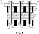
- FIG. 4 is a simplified cross-sectional illustration of an alternative needle array 110, which is arranged to complement tooling fixture 136.
- Tooling fixture 136 can be a graphite tooling fixture used for supporting preform 126 during CVI and other processing steps.
- Needle array 110 is substantially similar to needle array 10 of FIGS. 1 and 2 , having needles 112 removably mounted to and extending from backplate 114.
- Each needle 112 includes metallic body 116 with outer polymer sheath 118.
- Metallic bodies 116 and polymer sheaths 118 can be made from the same materials as metallic bodies 16 and polymer sheaths 18, respectively, and similarly formed.
- Needles 112 have a relatively short taper and are generally cylindrical between base 120 and tip 122. Collars 124 are also optionally included.
- Needle array 110 differs slightly in that needles 112 must be inserted through infiltration holes 138 of tooling fixture 136, in which preform 126 is mounted, in order to reach preform 126. Accordingly, needles 112 can be arranged on backplate 114 to correspond/align with infiltration holes 138. Backplate 114 delimits the extent to which needles 112 can be inserted into preform 126, as collars 124 and needles 112 have smaller respective diameters than infiltration holes 138. Collars 124 can therefore be mounted around needles 112 in a position offset from backplate 114.
- the z-channels formed by needle array 110 otherwise will be substantially similar to those shown in and discussed with respect to FIG. 3 , extending through the entire thickness of preform 126 between opposing surfaces 128. Although shown in isolation from a tooling fixture in FIGS. 1 and 2 , needle array 10 can also be used with a tooling fixture.
- a CMC component formed with the disclosed perforating means can be incorporated into aerospace, maritime, or industrial equipment, to name a few, non-limiting examples.
- a needle array suitable for perforating a fibrous preform includes a backplate, a plurality of needles removably attached to and extending away from the backplate, and a collar disposed around each of the plurality of needles.
- Each of the plurality of needles includes a metallic body, and a polymer sheath covering the metallic body.
- the needle array of the preceding paragraph can optionally include, additionally and/or alternatively, any one or more of the following features, configurations and/or additional components:
- the polymer sheath can include one of polyvinyl alcohol and polyvinyl butyral.
- the collar can be formed from a polymer material.
- the collar can abut the backplate.
- the collar can have a frustoconical geometry tapering from widest proximate the backplate to narrowest distal from the backplate.
- each of the plurality of needles can have a diameter ranging from 100 microns to 1,000 microns.
- a thickness of the polymer sheath can range from 0.05 microns to 127 microns.
- An assembly includes a tooling fixture for mounting a fibrous preform therein, the tooling fixture including a plurality of infiltration holes, and a needle array including a backplate, and a plurality of needles removably attached to and extending away from the backplate.
- Each of the plurality of needles includes a metallic body, and a polymer sheath covering the metallic body.
- Each of the plurality of needles is aligned with a respective infiltration hole of the plurality of infiltration holes.
- the tooling fixture can be formed from graphite.
- the polymer sheath can include one of polyvinyl alcohol and polyvinyl butyral.
- each of the plurality of needles can have a diameter ranging from 100 microns to 1,000 microns.
- a thickness of the polymer sheath can range from 0.05 microns to 127 microns.
- Any of the above assemblies can further include a collar disposed around each of the plurality of needles.
- the collar can be coated with a polymer material.
- the collar can be offset from the backplate.
- the collar cane have a frustoconical geometry.
- a method of preparing a fibrous preform for use in a ceramic matrix composite includes inserting a plurality of needles belonging to a needle array through the fibrous preform, removing the plurality of needles to form a plurality of z-channels in the fibrous preform, and subsequently heating the fibrous preform to decompose polymer contaminants within the plurality of z-channels.
- Each of the plurality of needles includes a metallic body, and a polymer sheath covering the metallic body.
- the polymer sheath can be formed from one of polyvinyl alcohol and polyvinyl butyral.
- the contaminants can be formed from the same material as the polymer sheath.
- the step of heating the fibrous preform can occur during chemical vapor infiltration.
Landscapes
- Engineering & Computer Science (AREA)
- Chemical & Material Sciences (AREA)
- Ceramic Engineering (AREA)
- Manufacturing & Machinery (AREA)
- Materials Engineering (AREA)
- Structural Engineering (AREA)
- Organic Chemistry (AREA)
- Inorganic Chemistry (AREA)
- Mechanical Engineering (AREA)
- Chemical Kinetics & Catalysis (AREA)
- Life Sciences & Earth Sciences (AREA)
- Forests & Forestry (AREA)
- Textile Engineering (AREA)
- Nonwoven Fabrics (AREA)
- Spinning Or Twisting Of Yarns (AREA)
- Inorganic Fibers (AREA)
- Treatment Of Fiber Materials (AREA)
Abstract
Description
- The present invention relates to the fabrication of ceramic matrix composites (CMCs) and, more particularly, to CMCs having improved properties for operating in gas turbine engines.
- In the processing of CMCs, there is a need to infiltrate matrix within and around fibrous tows to replace pore volume with dense matrix material. In a woven system, large voids often exist between adjacent tows of a preform. Such voids can become large defects after infiltration of the composite that are detrimental to composite properties. The pore network through a woven system is often highly tortuous for infiltrating reactant vapors, which leads to uneven deposition through the thickness of the preform.
- The formation of z-channels can create more direct pathways for reactant gases. However, the metallic needles commonly used to form z-channels can contaminate and/or deform the preform. For example, metallic particles from the needles can remain in the preform after needle removal. Such particles and the preform ceramic material(s) have dissimilar thermal and mechanical properties, thus their presence in the final CMC can be detrimental. Additionally, needle removal can create localized deformations (i.e., from "springback") on the preform surfaces leading to defects after chemical vapor infiltration (CVI). Improved means for perforating preforms are therefore desirable.
- A needle array suitable for perforating a fibrous preform includes a backplate, a plurality of needles removably attached to and extending away from the backplate, and a collar disposed around each of the plurality of needles. Each of the plurality of needles includes a metallic body, and a polymer sheath covering the metallic body.
- An assembly includes a tooling fixture for mounting a fibrous preform therein, the tooling fixture including a plurality of infiltration holes, and a needle array including a backplate, and a plurality of needles removably attached to and extending away from the backplate. Each of the plurality of needles includes a metallic body, and a polymer sheath covering the metallic body. Each of the plurality of needles is aligned with a respective infiltration hole of the plurality of infiltration holes.
- A method of preparing a fibrous preform for use in a ceramic matrix composite includes inserting a plurality of needles belonging to a needle array through the fibrous preform, removing the plurality of needles to form a plurality of z-channels in the fibrous preform, and subsequently heating the fibrous preform to decompose polymer contaminants within the plurality of z-channels. Each of the plurality of needles includes a metallic body, and a polymer sheath covering the metallic body.
- Features of embodiments are set forth in the dependent claims.
-
-
FIG. 1 is a simplified cross-sectional view of a needle array for creating z-channels in a fibrous preform. -
FIG. 2 is a simplified cross-sectional view of the needle array ofFIG. 1 inserted in a fibrous preform. -
FIG. 3 is a simplified cross-sectional view of the fibrous preform after removal of the needle array. -
FIG. 4 is a simplified cross-sectional view of an alternative needle array for use with tooling-mounted fibrous preforms. - While the above-identified figures set forth one or more embodiments of the present disclosure, other embodiments are also contemplated, as noted in the discussion. In all cases, this disclosure presents the invention by way of representation and not limitation. It should be understood that numerous other modifications and embodiments can be devised by those skilled in the art, which fall within the scope and spirit of the principles of the invention. The figures may not be drawn to scale, and applications and embodiments of the present invention may include features and components not specifically shown in the drawings.
- This disclosure presents a means for forming z-channels in a fibrous preform with reduced risk of contamination and/or surface deformation. More specifically, polymer sheaths can be formed over needles used to perforate preforms. Any polymer contaminants left in the preform are more easily removed than metallics. Further, the polymer sheaths can protect the underlying needles to extend useful life.
-
FIG. 1 is a simplified cross-sectional illustration ofneedle array 10.Needle array 10 includes a plurality ofneedles 12 extending away frombackplate 14.Needles 12 can be arranged in columns and rows, or other patterns.Needles 12 can be removably connected (e.g., via threaded engagement, mounting pins, etc.) to backplate 14 in an exemplary embodiment, and monolithically formed (e.g., via additive manufacturing) in an alternative embodiment. Eachneedle 12 can includemetallic body 16 and polymer sheath (or coating) 18.Backplate 14 can be formed from a metallic material. As shown, eachneedle 12 has a relatively short taper and is generally cylindrical along most of its length betweenbase 20 andtip 22. Medium to long tapers are also contemplated herein. Needle geometry is defined by the underlyingmetallic bodies 16.Polymer sheaths 18 can be formed from polyvinyl alcohol (PVA), polyvinyl butyral (PVB), or another suitable low-char polymer.Polymer sheaths 18 can be formed on metallic bodies by a spraying or melt-dipping process. As such,polymer sheaths 18 can be reapplied throughout the lifecycle of a givenneedle 12 orneedle array 10, as repeated use causes wear topolymer sheaths 18 and underlyingmetallic bodies 16. Eachneedle 12 can have a diameter D ranging from 100 microns to 1,000 microns, with all needles of a givenneedle array 10 having generally uniform diameters with respect to one another. Eachpolymer sheath 18 can be applied such that it only nominally increases the diameter of arespective needle 12, having a uniform thickness of about 0.05 microns to 127 microns, 0.05 microns to 50.8 microns, or 0.05 microns to 0.1 microns. Eachpolymer sheath 18 should be applied and/or maintained to cover a respectivemetallic body 16 substantially if not completely. -
Needle array 10 can further include an optional collar 24 (shown with dashed lines inFIG. 1 ) around eachneedle 12. Eachcollar 24 can have a frustoconical geometry tapering from a widest diameterproximate backplate 14 to a narrowest diameter as it reaches the exterior ofneedle 12 formed bypolymer sheath 18. For assembly ofneedle array 10, collars can be inserted overneedles 12, or attached tobackplate 14 prior to the attachment ofneedles 12.Collars 24 need not be positioned against/in contact withbackplate 14 but can be offset from backplate 14 (as shown inFIG. 4 ).Collars 24 can be similarly formed from a polymer-coated metallic material. Exemplary polymers can include PVA or PVB. In an alternative embodiment,collars 24 can be formed from a hardened plastic.Collars 24 can be used to compress the preform surface (labeled inFIGS. 2 and3 ) during insertion of needles to minimize frays at the preform surface from localized preform springback. -
FIG. 2 is a simplified cross-sectional illustration ofneedle array 10 inserted intopreform 26. Preform 26 can be formed from ceramic (e.g., silicon carbide - SiC) tows arranged in one of various two or three-dimensional woven architectures such as plain, harness (e.g., 3, 5, 8, etc.), twill, braid, or non-symmetric to name a few non-limiting examples. Non-woven architectures (e.g., chopped, felted, etc.) are also contemplated herein. As shown,needles 12 extend completely through the thickness ofpreform 26, that is between opposing (i.e., inner and outer)surfaces 28. Althoughcollars 24 are shown inserted intopreform 26 such thatplate 14 is near or flush withsurface 28,collars 24, if included onneedle array 10, need not be inserted to such extent. Prior to the insertion ofneedles 12, preform 26 can be in a dry but sized/re-sized state, or wetted with a liquid polymer tackifier.Needles 12 can be inserted throughpreform 26 at eithersurface 28, or sequentially through bothsurfaces 28. -
FIG. 3 is a simplified cross-sectional illustration ofpreform 26 ofFIG. 2 after the removal ofneedle array 10, which may have been inserted through eachsurface 28 ofpreform 26. As can be seen inFIG. 3 , needles 12 form z-channels 30 extending through the thickness ofpreform 26.Contaminants 32 can variously be left behind inpreform 26 as a result of the contact betweenpolymer sheaths 18 and the ceramic tows ofpreform 26.Contaminants 32 are pieces (e.g., flakes, particles, etc.) ofpolymer sheaths 18 and are therefore the same material aspolymer sheaths 18.Contaminants 32 can be thermally decomposed, in one example, during subsequent processing ofpreform 26 in which preform 26 is exposed to high temperatures. Such processing can include using CVI to form an interface coating (IFC) and/or CVI to form the ceramic (e.g., SiC) matrix. -
Preform 26 can includeangled segments 34 extending away from z-channels 30, which can result from pushingcollars 24 into arespective surface 28 ofpreform 26. Z-channels 30 are otherwise cylindrical, corresponding toneedle 12 geometry. Ifcollars 24 are not included onneedle array 10, or ifneedles 12 are inserted such thatcollars 24 do not make significant contact withpreform 26, angledsegments 34 may not be formed, and z-channels 30 can be entirely cylindrical, as is represented in dashed lines in the right-most z-channel 30 inFIG. 3 . -
FIG. 4 is a simplified cross-sectional illustration of analternative needle array 110, which is arranged to complementtooling fixture 136.Tooling fixture 136 can be a graphite tooling fixture used for supportingpreform 126 during CVI and other processing steps.Needle array 110 is substantially similar toneedle array 10 ofFIGS. 1 and2 , havingneedles 112 removably mounted to and extending frombackplate 114. Eachneedle 112 includesmetallic body 116 withouter polymer sheath 118.Metallic bodies 116 andpolymer sheaths 118 can be made from the same materials asmetallic bodies 16 andpolymer sheaths 18, respectively, and similarly formed.Needles 112 have a relatively short taper and are generally cylindrical betweenbase 120 andtip 122.Collars 124 are also optionally included. -
Needle array 110 differs slightly in that needles 112 must be inserted throughinfiltration holes 138 oftooling fixture 136, in which preform 126 is mounted, in order to reachpreform 126. Accordingly, needles 112 can be arranged onbackplate 114 to correspond/align with infiltration holes 138.Backplate 114 delimits the extent to which needles 112 can be inserted intopreform 126, ascollars 124 andneedles 112 have smaller respective diameters than infiltration holes 138.Collars 124 can therefore be mounted around needles 112 in a position offset frombackplate 114. The z-channels formed byneedle array 110 otherwise will be substantially similar to those shown in and discussed with respect toFIG. 3 , extending through the entire thickness ofpreform 126 between opposingsurfaces 128. Although shown in isolation from a tooling fixture inFIGS. 1 and2 ,needle array 10 can also be used with a tooling fixture. - A CMC component formed with the disclosed perforating means can be incorporated into aerospace, maritime, or industrial equipment, to name a few, non-limiting examples.
- The following are non-exclusive descriptions of possible embodiments of the present invention.
- A needle array suitable for perforating a fibrous preform includes a backplate, a plurality of needles removably attached to and extending away from the backplate, and a collar disposed around each of the plurality of needles. Each of the plurality of needles includes a metallic body, and a polymer sheath covering the metallic body.
- The needle array of the preceding paragraph can optionally include, additionally and/or alternatively, any one or more of the following features, configurations and/or additional components:
In the above needle array, the polymer sheath can include one of polyvinyl alcohol and polyvinyl butyral. - In any of the above needle arrays, the collar can be formed from a polymer material.
- In any of the above needle arrays, the collar can abut the backplate.
- In any of the above needle arrays, the collar can have a frustoconical geometry tapering from widest proximate the backplate to narrowest distal from the backplate.
- In any of the above needle arrays, each of the plurality of needles can have a diameter ranging from 100 microns to 1,000 microns.
- In any of the above needle arrays, a thickness of the polymer sheath can range from 0.05 microns to 127 microns.
- An assembly includes a tooling fixture for mounting a fibrous preform therein, the tooling fixture including a plurality of infiltration holes, and a needle array including a backplate, and a plurality of needles removably attached to and extending away from the backplate. Each of the plurality of needles includes a metallic body, and a polymer sheath covering the metallic body. Each of the plurality of needles is aligned with a respective infiltration hole of the plurality of infiltration holes.
- The assembly of the preceding paragraph can optionally include, additionally and/or alternatively, any one or more of the following features, configurations and/or additional components:
In the above assembly, the tooling fixture can be formed from graphite. - In any of the above assemblies, the polymer sheath can include one of polyvinyl alcohol and polyvinyl butyral.
- In any of the above assemblies, each of the plurality of needles can have a diameter ranging from 100 microns to 1,000 microns.
- In any of the above assemblies, a thickness of the polymer sheath can range from 0.05 microns to 127 microns.
- Any of the above assemblies can further include a collar disposed around each of the plurality of needles.
- In any of the above assemblies, the collar can be coated with a polymer material.
- In any of the above assemblies, the collar can be offset from the backplate.
- In any of the above assemblies, the collar cane have a frustoconical geometry.
- A method of preparing a fibrous preform for use in a ceramic matrix composite includes inserting a plurality of needles belonging to a needle array through the fibrous preform, removing the plurality of needles to form a plurality of z-channels in the fibrous preform, and subsequently heating the fibrous preform to decompose polymer contaminants within the plurality of z-channels. Each of the plurality of needles includes a metallic body, and a polymer sheath covering the metallic body.
- The method of the preceding paragraph can optionally include, additionally and/or alternatively, any one or more of the following features, configurations and/or additional components:
In the above method, the polymer sheath can be formed from one of polyvinyl alcohol and polyvinyl butyral. - In any of the above methods, the contaminants can be formed from the same material as the polymer sheath.
- In any of the above methods, the step of heating the fibrous preform can occur during chemical vapor infiltration.
- While the invention has been described with reference to an exemplary embodiment(s), it will be understood by those skilled in the art that various changes may be made and equivalents may be substituted for elements thereof without departing from the scope of the invention. In addition, many modifications may be made to adapt a particular situation or material to the teachings of the invention without departing from the essential scope thereof. Therefore, it is intended that the invention not be limited to the particular embodiment(s) disclosed, but that the invention will include all embodiments falling within the scope of the appended claims.
Claims (15)
- A needle array (10; 110) suitable for perforating a fibrous preform (26; 126), the needle array (10; 110) comprising:a backplate (14; 114);a plurality of needles (12; 112) removably attached to and extending away from the backplate (14; 114), each of the plurality of needles (10; 110) comprising:a metallic body (16; 116); anda polymer sheath (18; 118) covering the metallic body (16; 116); anda collar (24; 124) disposed around each of the plurality of needles (12; 112).
- The needle array (10; 110) of claim 1, wherein the collar (24; 124) is formed from a polymer material.
- The needle array (10) of claim 1 or 2, wherein the collar (24) abuts the backplate (14).
- The needle array (10; 110) of any preceding claim, wherein the collar (24; 124) has a frustoconical geometry tapering from widest proximate the backplate (14; 114) to narrowest distal from the backplate (14; 114).
- An assembly comprising:a tooling fixture (136) for mounting a fibrous preform (26; 126) therein, the tooling fixture (136) comprising a plurality of infiltration holes (138); anda needle array (10; 110) comprising:a backplate (14; 114);a plurality of needles (12; 112) removably attached to and extending away from the backplate (14; 114), each of the plurality of needles (12; 112) comprising:a metallic body (16; 116); anda polymer sheath (18; 118) covering the metallic body (16; 116);wherein each of the plurality of needles (12; 112) is aligned with a respective infiltration hole (138) of the plurality of infiltration holes (138).
- The assembly of claim 5 or needle array of any of claims 1 to 4, wherein the polymer sheath (18; 118) comprises one of polyvinyl alcohol and polyvinyl butyral.
- The assembly of claim 5 or 6 or needle array of any of claims 1 to 4 or 6, wherein each of the plurality of needles (12; 112) has a diameter (D) ranging from 100 microns to 1,000 microns.
- The assembly of any of claims 5 to 7 or needle array of any of claims 1 to 4, 6 or 7, wherein a thickness of the polymer sheath (18; 118) ranges from 0.05 microns to 127 microns.
- The assembly of any of claims 5 to 8, wherein the tooling fixture (136) is formed from graphite.
- The assembly of any of claims 5 to 9 and further comprising: a collar (24; 124) disposed around each of the plurality of needles (12; 112).
- The assembly of claim 10, wherein the collar (24; 124) is coated with a polymer material.
- The assembly of claim 10 or 11, wherein the collar (124) is offset from the backplate (114); and/or wherein the collar (24; 124) has a frustoconical geometry.
- A method of preparing a fibrous preform (26; 126) for use in a ceramic matrix composite, the method comprising:
inserting a plurality of needles (12; 112) belonging to a needle array (10; 110) through the fibrous preform (26; 126), each of the plurality of needles (12; 112) comprising:a metallic body (16; 116); anda polymer sheath (18; 118) covering the metallic body (16; 116);removing the plurality of needles (12; 112) to form a plurality of z-channels (30) in the fibrous preform (26; 126); andsubsequently, heating the fibrous preform (26; 126) to decompose polymer contaminants (32) within the plurality of z-channels (30). - The method of claim 13, wherein the polymer sheath (18; 118) is formed from one of polyvinyl alcohol and polyvinyl butyral; and/or wherein the contaminants (32) are formed from the same material as the polymer sheath (18; 118).
- The method of claim 13 or 14, wherein the step of heating the fibrous preform (26; 126) occurs during chemical vapor infiltration.
Applications Claiming Priority (1)
| Application Number | Priority Date | Filing Date | Title |
|---|---|---|---|
| US18/123,037 US12545628B2 (en) | 2023-03-17 | 2023-03-17 | Sheathed metallic needles for producing z-channels in fibrous preforms |
Publications (2)
| Publication Number | Publication Date |
|---|---|
| EP4431254A2 true EP4431254A2 (en) | 2024-09-18 |
| EP4431254A3 EP4431254A3 (en) | 2025-01-01 |
Family
ID=90365983
Family Applications (1)
| Application Number | Title | Priority Date | Filing Date |
|---|---|---|---|
| EP24163852.7A Pending EP4431254A3 (en) | 2023-03-17 | 2024-03-15 | Sheathed metallic needles for producing z-channels in fibrous preforms |
Country Status (2)
| Country | Link |
|---|---|
| US (1) | US12545628B2 (en) |
| EP (1) | EP4431254A3 (en) |
Families Citing this family (3)
| Publication number | Priority date | Publication date | Assignee | Title |
|---|---|---|---|---|
| US20240300861A1 (en) * | 2023-03-07 | 2024-09-12 | Raytheon Technologies Corporation | Method of reducing surface deformation from z-channel creation |
| US12473236B2 (en) * | 2023-10-20 | 2025-11-18 | Rtx Corporation | Internal tooling configuration for the creation of z-channels in woven ceramic matrix composite preforms |
| US12552085B2 (en) * | 2023-10-20 | 2026-02-17 | Rtx Corporation | Z-channeling into a preform via needle perforation in a stand-alone tool |
Citations (1)
| Publication number | Priority date | Publication date | Assignee | Title |
|---|---|---|---|---|
| EP4375038A1 (en) * | 2022-11-15 | 2024-05-29 | Rohr, Inc. | Methods for selective needling of fibrous preforms for shape-forming |
Family Cites Families (55)
| Publication number | Priority date | Publication date | Assignee | Title |
|---|---|---|---|---|
| US2289177A (en) | 1939-02-09 | 1942-07-07 | Perfotex Company | Composite foraminous material |
| US2611434A (en) | 1948-01-12 | 1952-09-23 | Charles M Mugler | Coring or perforating device |
| US3877120A (en) | 1970-02-20 | 1975-04-15 | Toray Industries | Needle board |
| DE2343646A1 (en) | 1973-08-30 | 1975-03-27 | Gallus Herrenschuhfabrik H Vog | Porous plastics sheet for shoes - is perforated by conical needles from inner face giving small pores outside |
| GB2025302A (en) | 1978-07-15 | 1980-01-23 | Rolls Royce | Perforating Sheets |
| US4486372A (en) | 1983-09-30 | 1984-12-04 | Rohr Industries, Inc. | Method for fabricating contoured perforated composite laminate structure |
| US5188625A (en) | 1985-09-09 | 1993-02-23 | Kimberly-Clark Corporation | Sanitary napkin having a cover formed from a nonwoven web |
| JPS62264896A (en) | 1986-05-12 | 1987-11-17 | 町田 輝史 | Manufacture of fiber-reinforced composite material with joining hole |
| US4767095A (en) | 1986-12-23 | 1988-08-30 | Fitzgerald John M | Concrete column form |
| AT392095B (en) * | 1989-02-27 | 1991-01-25 | Fehrer Textilmasch | NEEDLE BOARD FOR A DEVICE FOR NEEDLING A FLEECE |
| US5066442A (en) | 1989-02-28 | 1991-11-19 | Massachusetts Institute Of Technology | Method of producing a composite article |
| US5246520A (en) | 1991-02-12 | 1993-09-21 | Auto-Air Composites, Inc. | One step molded continuous fiber reinforced perforated composite panels |
| IT1260632B (en) | 1993-03-29 | 1996-04-22 | Sepi Spa | PROCESS AND EQUIPMENT FOR THE MANUFACTURE OF A PADDED ELEMENT, IN PARTICULAR FOR A VEHICLE SEAT. |
| US5372494A (en) | 1994-01-25 | 1994-12-13 | Reynolds Metals Company | Adjustable perforating roller for sheet material |
| US5560881A (en) * | 1994-06-08 | 1996-10-01 | Usg Interiors, Inc. | Apparatus for producing a fissured, acoustical ceiling panel and method for manufacturing said apparatus |
| US5515585A (en) | 1994-07-25 | 1996-05-14 | The Bf Goodrich Company | Process for forming needled fibrous structures using determined transport depth |
| KR980700904A (en) | 1996-02-27 | 1998-04-30 | 고오사이 아끼오 | Method for manufacturing the complex |
| US5952075A (en) * | 1997-09-08 | 1999-09-14 | Fiberite, Inc. | Needled near netshape carbon preforms having polar woven substrates and methods of producing same |
| US6190602B1 (en) | 1998-03-13 | 2001-02-20 | Aztex, Inc. | Method of manufacturing a perforated laminate |
| US6083436A (en) | 1999-03-26 | 2000-07-04 | Aircraft Braking Systems Corp. | Apparatus and technique for making carbon brake discs |
| US6203738B1 (en) | 1999-03-29 | 2001-03-20 | Masonite Corporation | Method for providing more uniform density in the manufacture of lightweight structural fiberboard panels |
| US6233797B1 (en) | 1999-07-13 | 2001-05-22 | Groz Beckert Kg | Felt needle |
| US6837956B2 (en) * | 2001-11-30 | 2005-01-04 | Kimberly-Clark Worldwide, Inc. | System for aperturing and coaperturing webs and web assemblies |
| FR2833204B1 (en) | 2001-12-11 | 2004-05-28 | Snecma | REALIZATION OF NEEDLE FIBROUS PREFORM FOR MANUFACTURING A PART OF COMPOSITE MATERIAL |
| DE10305159B4 (en) * | 2002-11-02 | 2006-12-07 | Rowapack Gmbh Verpackungsdesign Und Stanztechnik | stamping |
| FR2852003B1 (en) | 2003-03-04 | 2005-05-27 | Snecma Propulsion Solide | PROCESS FOR PRODUCING A MULTIPERFORATED PART IN CERAMIC MATRIX COMPOSITE MATERIAL |
| FR2852004B1 (en) | 2003-03-04 | 2005-05-27 | Snecma Propulsion Solide | REALIZING A PREFORM BY STRENGTHENING A FIBROUS STRUCTURE AND / OR LINKING FIBROUS STRUCTURES BETWEEN THEM AND APPLYING THEM TO PRODUCING COMPOSITE MATERIALS |
| US20070149080A1 (en) | 2004-03-30 | 2007-06-28 | Nobuo Asahara | Preform, frp, and processes for producing these |
| US20080125745A1 (en) * | 2005-04-19 | 2008-05-29 | Shubhayu Basu | Methods and compositions for treating post-cardial infarction damage |
| US7997891B2 (en) | 2007-04-12 | 2011-08-16 | Purdue Research Foundation | Molding processes and tool therefor |
| US20080287884A1 (en) * | 2007-04-17 | 2008-11-20 | Warden Matthew P | Convertible syringe system |
| FR2924426B1 (en) | 2007-11-30 | 2011-06-03 | Messier Bugatti | PROCESS FOR MANUFACTURING COMPOSITE MATERIAL PARTS WITH CARBON FIBER REINFORCEMENT |
| US8128775B2 (en) | 2008-12-30 | 2012-03-06 | Mra Systems, Inc. | Process and apparatus for producing composite structures |
| CN201483574U (en) * | 2009-04-20 | 2010-05-26 | 北京新时基业绝热纤维喷涂技术有限公司 | Needle pricking board for pricking holes |
| DE102009020708A1 (en) | 2009-05-11 | 2010-11-18 | Pallmann Maschinenfabrik Gmbh & Co Kg | Device for crushing feedstock |
| US9017761B2 (en) | 2009-05-20 | 2015-04-28 | Honeywell International Inc. | Low cost, high density C-C composites densified by CVD/CVI for aircraft friction materials |
| FR2951664B1 (en) | 2009-10-23 | 2011-12-16 | Hexcel Reinforcements | MULTIAXIAL STACK SOLIDARIZED BY SINGLE WELTS PRODUCED BY INTERCALAR THERMOPLASTIC SAILS |
| FR2954358B1 (en) * | 2009-12-23 | 2012-01-13 | Messier Bugatti | CIRCULAR CLAMPING TABLE FOR TEXTILE STRUCTURE FORMED FROM ANNIBLE FIBROUS PREFORM |
| WO2013089994A1 (en) * | 2011-12-15 | 2013-06-20 | Faurecia Interior Systems, Inc. | Non-visible tear seams for airbag coverings |
| KR101394955B1 (en) | 2012-09-07 | 2014-05-14 | 경상대학교산학협력단 | Z-pinning device |
| US9708226B2 (en) | 2013-03-15 | 2017-07-18 | Rolls-Royce Corporation | Method for producing high strength ceramic matrix composites |
| US10005246B2 (en) | 2013-08-22 | 2018-06-26 | Faurecia Interior Systems, Inc. | Methods for making interior panels for motor vehicles |
| US10414142B2 (en) * | 2014-12-29 | 2019-09-17 | Rolls-Royce Corporation | Needle punching of composites for preform assembly and thermomechanical enhancement |
| US9546438B2 (en) | 2015-04-23 | 2017-01-17 | Goodrich Corporation | Low z high performance carbon composite materials |
| US9856592B2 (en) | 2016-03-15 | 2018-01-02 | Goodrich Corporation | Methods and systems for forming a fibrous preform |
| US10894746B2 (en) | 2016-10-19 | 2021-01-19 | Rolls-Royce Corporation | Ceramic matrix composite reinforced material |
| FR3059268B1 (en) | 2016-11-25 | 2020-02-21 | Safran Aircraft Engines | PROCESS FOR MANUFACTURING A PROFILE ELEMENT IN COMPOSITE MATERIAL WITH FIXING OF A METAL REINFORCEMENT BY RIVETING. |
| CN108127937B (en) | 2017-12-26 | 2021-01-15 | 江苏德晴新材股份有限公司 | Integrative seam needle of combined material needle and line |
| CN108215246B (en) | 2018-03-09 | 2024-05-24 | 湖南航天环宇通信科技股份有限公司 | Forming tool for porous composite part and using method thereof |
| FR3093298B1 (en) | 2019-03-01 | 2021-03-12 | Safran | Repair or resumption of manufacture of a composite material part |
| CN112077930A (en) | 2020-10-16 | 2020-12-15 | 沈威 | Paper tape equal-length cutting mechanism and paper tape punching equipment thereof |
| GB2606342A (en) | 2021-04-27 | 2022-11-09 | Rolls Royce Plc | Fibre reinforced gas turbine engine component |
| US20240109223A1 (en) | 2022-09-30 | 2024-04-04 | Raytheon Technologies Corporation | Spiked preform tooling for improved chemical vapor infiltration in ceramic matrix composites |
| US12318964B2 (en) * | 2023-01-17 | 2025-06-03 | Goodrich Corporation | Conformable tooling systems and methods for complex contour composite preforms |
| US20240308922A1 (en) * | 2023-03-17 | 2024-09-19 | Raytheon Technologies Corporation | Tooling for producing z-channels in ceramic fiber preforms |
-
2023
- 2023-03-17 US US18/123,037 patent/US12545628B2/en active Active
-
2024
- 2024-03-15 EP EP24163852.7A patent/EP4431254A3/en active Pending
Patent Citations (1)
| Publication number | Priority date | Publication date | Assignee | Title |
|---|---|---|---|---|
| EP4375038A1 (en) * | 2022-11-15 | 2024-05-29 | Rohr, Inc. | Methods for selective needling of fibrous preforms for shape-forming |
Also Published As
| Publication number | Publication date |
|---|---|
| US12545628B2 (en) | 2026-02-10 |
| EP4431254A3 (en) | 2025-01-01 |
| US20240308921A1 (en) | 2024-09-19 |
Similar Documents
| Publication | Publication Date | Title |
|---|---|---|
| US12545628B2 (en) | Sheathed metallic needles for producing z-channels in fibrous preforms | |
| EP4541535A1 (en) | Z-channeling into a preform via needle perforation in a stand-alone tool | |
| US8057880B2 (en) | Non-oxide selectively porous materials | |
| EP4434701B1 (en) | Tooling for producing z-channels in ceramic fiber preforms | |
| US20240109223A1 (en) | Spiked preform tooling for improved chemical vapor infiltration in ceramic matrix composites | |
| EP2373596B1 (en) | Method for processing ceramic fibres | |
| EP4454842A1 (en) | Z-channel creation in woven preform by incorporation of pin features into preform tooling | |
| EP3502307B1 (en) | Method of increasing the uniformity of chemical vapor deposition on fibrous material through the imposition of pressure waves | |
| EP4446076A1 (en) | A method of forming a ceramic matrix composite, and a pin array | |
| EP4286127B1 (en) | A fibrous preform comprising a plurality of hourglass-shaped voids | |
| EP3760604B1 (en) | Method of forming cooling channels in a ceramic matrix composite component | |
| EP4512789A1 (en) | Polymer towpreg for ceramic matrix composites | |
| JP2001206779A (en) | Method and apparatus for manufacturing fiber-reinforced composite member | |
| US20240109816A1 (en) | Ceramic matrix composite tooling for chemical vapor infiltration process | |
| US20110168431A1 (en) | Electric conductor and method for manufacturing an electric conductor | |
| EP4414346B1 (en) | Coatings for tooling | |
| US20250100941A1 (en) | Auxetic materials and structures for ceramic matrix composite airfoil mandrels | |
| EP4538251A1 (en) | Dispersion of filaments | |
| US12473236B2 (en) | Internal tooling configuration for the creation of z-channels in woven ceramic matrix composite preforms |
Legal Events
| Date | Code | Title | Description |
|---|---|---|---|
| PUAI | Public reference made under article 153(3) epc to a published international application that has entered the european phase |
Free format text: ORIGINAL CODE: 0009012 |
|
| STAA | Information on the status of an ep patent application or granted ep patent |
Free format text: STATUS: THE APPLICATION HAS BEEN PUBLISHED |
|
| AK | Designated contracting states |
Kind code of ref document: A2 Designated state(s): AL AT BE BG CH CY CZ DE DK EE ES FI FR GB GR HR HU IE IS IT LI LT LU LV MC ME MK MT NL NO PL PT RO RS SE SI SK SM TR |
|
| PUAL | Search report despatched |
Free format text: ORIGINAL CODE: 0009013 |
|
| AK | Designated contracting states |
Kind code of ref document: A3 Designated state(s): AL AT BE BG CH CY CZ DE DK EE ES FI FR GB GR HR HU IE IS IT LI LT LU LV MC ME MK MT NL NO PL PT RO RS SE SI SK SM TR |
|
| RIC1 | Information provided on ipc code assigned before grant |
Ipc: D04H 18/02 20120101ALI20241126BHEP Ipc: C04B 35/634 20060101ALI20241126BHEP Ipc: C04B 35/565 20060101ALI20241126BHEP Ipc: C04B 35/80 20060101ALI20241126BHEP Ipc: B26D 1/00 20060101ALI20241126BHEP Ipc: B29B 11/16 20060101ALI20241126BHEP Ipc: B26F 1/44 20060101ALI20241126BHEP Ipc: B26F 1/24 20060101AFI20241126BHEP |
|
| STAA | Information on the status of an ep patent application or granted ep patent |
Free format text: STATUS: REQUEST FOR EXAMINATION WAS MADE |
|
| 17P | Request for examination filed |
Effective date: 20250627 |
|
| STAA | Information on the status of an ep patent application or granted ep patent |
Free format text: STATUS: EXAMINATION IS IN PROGRESS |
|
| 17Q | First examination report despatched |
Effective date: 20260216 |