EP4431248A1 - Robot and robot system - Google Patents
Robot and robot system Download PDFInfo
- Publication number
- EP4431248A1 EP4431248A1 EP24161033.6A EP24161033A EP4431248A1 EP 4431248 A1 EP4431248 A1 EP 4431248A1 EP 24161033 A EP24161033 A EP 24161033A EP 4431248 A1 EP4431248 A1 EP 4431248A1
- Authority
- EP
- European Patent Office
- Prior art keywords
- arm
- hole
- locking
- robot
- contact portion
- Prior art date
- Legal status (The legal status is an assumption and is not a legal conclusion. Google has not performed a legal analysis and makes no representation as to the accuracy of the status listed.)
- Granted
Links
Images







Classifications
-
- B—PERFORMING OPERATIONS; TRANSPORTING
- B25—HAND TOOLS; PORTABLE POWER-DRIVEN TOOLS; MANIPULATORS
- B25J—MANIPULATORS; CHAMBERS PROVIDED WITH MANIPULATION DEVICES
- B25J17/00—Joints
-
- B—PERFORMING OPERATIONS; TRANSPORTING
- B25—HAND TOOLS; PORTABLE POWER-DRIVEN TOOLS; MANIPULATORS
- B25J—MANIPULATORS; CHAMBERS PROVIDED WITH MANIPULATION DEVICES
- B25J9/00—Program-controlled manipulators
- B25J9/02—Program-controlled manipulators characterised by movement of the arms, e.g. cartesian coordinate type
- B25J9/04—Program-controlled manipulators characterised by movement of the arms, e.g. cartesian coordinate type by rotating at least one arm, excluding the head movement itself, e.g. cylindrical coordinate type or polar coordinate type
-
- B—PERFORMING OPERATIONS; TRANSPORTING
- B25—HAND TOOLS; PORTABLE POWER-DRIVEN TOOLS; MANIPULATORS
- B25J—MANIPULATORS; CHAMBERS PROVIDED WITH MANIPULATION DEVICES
- B25J9/00—Program-controlled manipulators
- B25J9/08—Program-controlled manipulators characterised by modular constructions
-
- B—PERFORMING OPERATIONS; TRANSPORTING
- B25—HAND TOOLS; PORTABLE POWER-DRIVEN TOOLS; MANIPULATORS
- B25J—MANIPULATORS; CHAMBERS PROVIDED WITH MANIPULATION DEVICES
- B25J9/00—Program-controlled manipulators
- B25J9/10—Program-controlled manipulators characterised by positioning means for manipulator elements
- B25J9/1005—Program-controlled manipulators characterised by positioning means for manipulator elements comprising adjusting means
- B25J9/101—Program-controlled manipulators characterised by positioning means for manipulator elements comprising adjusting means using limit-switches, -stops
Definitions
- the present disclosure relates to a robot and a robot system.
- JP-A-11-123690 discloses a robot including a first arm and a second arm rotatably coupled to the first arm via a joint.
- the robot includes a stopper restricting an angle between the first arm and the second arm to a predetermined angle or more.
- the stopper includes a fixed-side stopper provided in the first arm and a movable-side stopper provided in the second arm. The movable-side stopper comes into contact with the fixed-side stopper, and thereby, the angle between the arms is restricted to the predetermined angle or more.
- the first arm and the second arm may be damaged due to an impact when the movable-side stopper comes into contact with the fixed-side stopper.
- a robot includes a first member, a second member rotatably coupled to the first member, a restricting member having a contact portion in contact with the first member when an angle between the first member and the second member is a predetermined angle and a through hole formed therein, a first locking member locking the restricting member to the second member through the through hole, and a second locking member locking the restricting member to the second member, wherein a distance between the contact portion and the first locking member is shorter than a distance between the contact portion and the second locking member, and the through hole is formed in a long hole shape longer than a diameter of the first locking member from the first locking member toward the contact portion.
- a robot system includes a robot and a controller controlling the robot, wherein the robot includes a first member, a second member rotatably coupled to the first member, a restricting member having a contact portion in contact with the first member when an angle between the first member and the second member is a predetermined angle and a through hole formed therein, a first locking member locking the restricting member to the second member through the through hole, and a second locking member locking the restricting member to the second member, wherein a distance between the contact portion and the first locking member is shorter than a distance between the contact portion and the second locking member, and the through hole is formed to be longer than a diameter of the first locking member from the first locking member toward the contact portion.
- a robot system 1 includes a robot 2 and a controller 3.
- the robot 2 is a kind of vertical articulated robot.
- the controller 3 controls the robot 2.
- the robot 2 includes a base 5, a first arm 6, a second arm 7, a third arm 8, a fourth arm 9, a fifth arm 10, and a sixth arm 11.
- the base 5 is installed on an installation surface 13 of a floor, a workbench, or the like.
- the first arm 6 is rotatably coupled to the base 5.
- the first arm 6 is coupled to the base 5 at an opposite side to the installation surface 13 side of the base 5.
- the first arm 6 is an example of a first member.
- the first arm 6 is rotatable around a first axis J1.
- the second arm 7 is rotatably coupled to the first arm 6.
- the second arm 7 is coupled to the first arm 6 at an opposite side to the base 5 side of the first arm 6.
- the second arm 7 is an example of a second member.
- the second arm 7 is rotatable around a second axis J2.
- the second axis J2 is a rotation axis of the second arm 7.
- the third arm 8 is rotatably coupled to the second arm 7.
- the third arm 8 is coupled to the second arm 7 at an opposite side to the first arm 6 side of the second arm 7.
- the third arm 8 is rotatable around a third axis J3.
- the fourth arm 9 is rotatably coupled to the third arm 8.
- the fourth arm 9 is coupled to the third arm 8 at an opposite side to the second arm 7 side of the third arm 8.
- the fourth arm 9 is rotatable around a fourth axis J4.
- the fifth arm 10 is rotatably coupled to the fourth arm 9.
- the fifth arm 10 is coupled to the fourth arm 9 at an opposite side to the third arm 8 side of the fourth arm 9.
- the fifth arm 10 is rotatable around a fifth axis J5.
- the sixth arm 11 is rotatably coupled to the fifth arm 10.
- the sixth arm 11 is coupled to the fifth arm 10 at an opposite side to the fourth arm 9 side of the fifth arm 10.
- the sixth arm 11 is rotatable around a sixth axis J6.
- the robot 2 is a six-axis robot having the six rotation axes from the first axis J1 to the sixth axis J6.
- An end effector (not shown) may be attached to the sixth arm 11.
- the end effector is detachable from the sixth arm 11. End effectors of types according to various kinds of work may be attached to the robot 2.
- the controller 3 is coupled to the robot 2.
- the robot 2 and the controller 3 can communicate with each other.
- the controller 3 transmits various control signals to the robot 2.
- the robot 2 performs various kinds of work based on the control signals received from the controller 3.
- the coupling between the robot 2 and the controller 3 may be wired or wireless.
- FIG. 2 is a perspective view showing the base 5, the first arm 6, and the second arm 7 of the robot 2.
- the robot 2 has a stopper unit 15.
- the stopper unit 15 is an example of a restricting member.
- the stopper unit 15 is provided on the second arm 7.
- the stopper unit 15 is locked to the second arm 7 by a first bolt 16 and a second bolt 17.
- the first bolt 16 is an example of a first locking member.
- the second bolt 17 is an example of a second locking member.
- the stopper unit 15 is provided on a surface crossing the second axis J2 of the second arm 7.
- the stopper unit 15 includes a stopper member 18, a first contact member 19, and a second contact member 20.
- the stopper member 18 is a rod-shaped plate member formed using a metal.
- the stopper member 18 is curved in an arc shape as seen along the second axis J2.
- the stopper member 18 is along an arc around the second axis J2.
- the first contact member 19 is provided on one end of the arc-shaped stopper member 18.
- the first contact member 19 is an example of a contact portion.
- the second contact member 20 is provided on the other end of the arc-shaped stopper member 18.
- the first contact member 19 and the second contact member 20 are respectively formed using hard rubber.
- the angle ⁇ 1 is an angle between the first arm 6 and the second arm 7 in a direction from the second contact member 20 toward the first contact member 19.
- the direction from the second contact member 20 toward the first contact member 19 is referred to as "first direction D1”.
- a direction from the first contact member 19 toward the second contact member 20 is referred to as "second direction D2".
- the first contact member 19 is located in an end portion of the stopper unit 15 in the first direction D1.
- the second contact member 20 is located in an end portion of the stopper unit 15 in the second direction D2.
- a first receiving portion 21 is provided in a position facing the first contact member 19.
- the first receiving portion 21 is provided in a position that the first contact member 19 faces when the second arm 7 rotates in the first direction D1.
- the first receiving portion 21 is provided in a concave shape in the first arm 6.
- the first contact member 19 of the stopper unit 15 contacts the first arm 6 before the second arm 7 collides with the first arm 6. That is, when the second arm 7 rotates around the second axis J2 in the first direction D1, the angle ⁇ 1 between the first arm 6 and the second arm 7 may be restricted by the stopper unit 15. Thereby, a collision between the first arm 6 and the second arm 7 may be avoided.
- the first contact member 19 of the stopper unit 15 contacts the first receiving portion 21 of the first arm 6 shown in FIG. 3 .
- a second receiving portion 22 is provided in a position facing the second contact member 20.
- the second receiving portion 22 is provided in a position that the second contact member 20 faces when the second arm 7 rotates in the second direction D2.
- the second receiving portion 22 is provided in a concave shape in the first arm 6.
- the second contact member 20 of the stopper unit 15 contacts the first arm 6 before the second arm 7 collides with the first arm 6. That is, when the second arm 7 rotates around the second axis J2 in the second direction D2, the angle ⁇ 2 between the first arm 6 and the second arm 7 may be restricted by the stopper unit 15. Thereby, a collision between the first arm 6 and the second arm 7 may be avoided. Note that the second contact member 20 of the stopper unit 15 contacts the second receiving portion 22 of the first arm 6 shown in FIG. 5 .
- a first through hole 24 and a second through hole 25 are formed in the stopper member 18.
- the first through hole 24 and the second through hole 25 respectively penetrate the stopper member 18 and reach the second arm 7.
- a first screw hole 26 and a second screw hole 27 are formed in the second arm 7.
- the first screw hole 26 overlaps with the first through hole 24 when the stopper member 18 and the second arm 7 are seen along the second axis J2.
- the second screw hole 27 overlaps with the second through hole 25 when the stopper member 18 and the second arm 7 are seen along the second axis J2.
- the first bolt 16 is fastened into the first screw hole 26 of the second arm 7 through the first through hole 24 of the stopper member 18. That is, the first bolt 16 locks the stopper unit 15 to the second arm 7 through the first through hole 24.
- the second bolt 17 is fastened into the second screw hole 27 of the second arm 7 through the second through hole 25 of the stopper member 18. That is, the second bolt 17 locks the stopper unit 15 to the second arm 7 through the second through hole 25.
- the distance between the first contact member 19 and the first through hole 24 is shorter than the distance between the first contact member 19 and the second through hole 25. That is, the first through hole 24 is located at one end side of the stopper unit 15 in the first direction D1.
- the second through hole 25 is located at the other end side of the stopper unit 15 in the second direction D2. Accordingly, when the stopper unit 15 and the second arm 7 are seen along the second axis J2, the distance between the first contact member 19 and the first bolt 16 is shorter than the distance between the first contact member 19 and the second bolt 17.
- the first through hole 24 of the stopper unit 15 is formed in a long hole shape.
- the long hole shape of the first through hole 24 is a shape longer than the diameter of the first bolt 16 from the first bolt 16 toward the first contact member 19. According to the robot 2, when the first contact member 19 contacts the first arm 6, an impact may be relaxed by a friction between the stopper unit 15 and the first bolt 16. In other words, when the first contact member 19 of the stopper unit 15 contacts the first arm 6, an impact force applied to the first bolt 16 by the stopper unit 15 may be relaxed. Accordingly, the damage on the first arm 6 and the second arm 7 may be reduced.
- the second through hole 25 of the stopper unit 15 is formed in a long hole shape.
- the long hole shape of the second through hole 25 is a shape longer than the diameter of the second bolt 17 from the second bolt 17 toward the second contact member 20.
- the long hole shape of the first through hole 24 extends along the first direction D1.
- the extension direction of the long hole shape of the first through hole 24 is easily aligned with a direction of a force acting on the stopper unit 15 when the first contact member 19 contacts the first arm 6. Accordingly, the impact force applied to the first bolt 16 by the stopper unit 15 may be relaxed.
- the long hole shape of the second through hole 25 extends along the second direction D2.
- the extension direction of the long hole shape of the second through hole 25 is easily aligned with a direction of a force acting on the stopper unit 15 when the second contact member 20 contacts the first arm 6. Accordingly, the impact force applied to the second bolt 17 by the stopper unit 15 may be relaxed.
- the first through hole 24 has a width dimension H1 in a direction crossing the extension direction of the long hole shape smaller from the first bolt 16 toward the first contact member 19.
- a force in the second direction D2 is applied to the stopper unit 15 by the first arm 6.
- the stopper unit 15 tends to be displaced in the second direction D2 relative to the second arm 7.
- the first bolt 16 may deform the stopper member 18 in a direction in which the width dimension H1 of the first through hole 24 is increased. Accordingly, the impact force applied to the first bolt 16 by the stopper unit 15 may be relaxed.
- the second through hole 25 has a width dimension H2 in a direction crossing the extension direction of the long hole shape smaller from the second bolt 17 toward the second contact member 20.
- a force in the first direction D1 is applied to the stopper unit 15 by the first arm 6.
- the stopper unit 15 tends to be displaced in the first direction D1 relative to the second arm 7.
- the second bolt 17 may deform the stopper member 18 in a direction in which the width dimension H2 of the second through hole 25 is increased. Accordingly, the impact force applied to the second bolt 17 by the stopper unit 15 may be relaxed.
- the long sides of the long hole shape of the first through hole 24 are tapered on both sides.
- “tapered on both sides” refers to a state in which both of two long sides of the long hole shape are inclined relative to tangent lines L2.
- the tangent lines L2 are tangent lines of the first through hole 24 at intersections between a line segment L1 and the first through hole 24.
- the line segment L1 is a straight line passing through the center of the first bolt 16 from the position of the second axis J2 and crossing the stopper member 18.
- the long sides of the long hole shape of the second through hole 25 shown in FIG. 8 are tapered on both sides.
- the long sides of the long hole shapes of the first through hole 24 and the second through hole 25 are not limited to those tapered on both sides. As shown in FIG. 10 , the long sides of the long hole shapes of the first through hole 24 and the second through hole 25 may be respectively tapered on one sides. “Tapered on one side” refers to a state in which one of the two long sides of the long hole shape is tapered and the other of the long sides extends along the tangent line L2. In “tapered on one side”, either of the two long sides of the long hole shape may be tapered. Even when one side of the long sides of the long hole shape is tapered, the same effect as that of "tapered on both sides” may be obtained.
- the two long sides of the long hole shape are not limited to the straight lines.
- the two long sides of the long hole shape may be curved lines.
- a configuration in which one of the two long sides of the long hole shape is a curved line and the other is a straight line may be applied.
- As the curved line forming the long side e.g., an arc is applied. Even in a configuration in which at least one of the two long sides of the long hole shape is a curved line, the same effect as that of "tapered on both sides" may be obtained.
- the dimension of a first part 31 is smaller than the dimension of a second part 32.
- the line segment L1 is the straight line passing through the center of the first bolt 16 from the position of the second axis J2 and crossing the stopper member 18. Accordingly, the line segment L1 crosses the stopper unit 15 from the second axis J2 via the first through hole 24 as seen from the direction along the second axis J2.
- the first part 31 is a part between the first through hole 24 and the second axis J2 of the parts in which the line segment L1 and the stopper unit 15 overlap.
- the second part 32 is a part in a position over the first through hole 24 from the second axis J2.
- the first part 31 is located at the inner side of the first through hole 24.
- the second part 32 is located at an outer side of the first part 31 as seen from the position of the second axis J2.
- the dimension of the first part 31 located at the inner side of the first through hole 24 is smaller than the dimension of the second part 32 located at the outer side of the first through hole 24.
- the rigidity of the first part 31 is lower than the rigidity of the second part 32. According to the configuration, when the first bolt 16 deforms the stopper member 18 in a direction in which the width dimension of the first through hole 24 is increased, the deformation of the first part 31 may be made larger than that of the second part 32. Accordingly, an impact force applied to the first arm 6 outward by the first bolt 16 may be relaxed.
- a configuration having a cutout portion 35 may be applied.
- the cutout portion 35 is an example of a first cutout portion.
- the cutout portion 35 is formed in the stopper member 18.
- the cutout portion 35 is formed between the first through hole 24 and the second through hole 25.
- the cutout portion 35 is formed between the first bolt 16 and the second bolt 17.
- the cutout portion 35 is formed at the second axis J2 side of the stopper member 18.
- the cutout portion 35 is formed at the second axis J2 side as a rotation center of the second arm 7. That is, the cutout portion 35 is formed at the rotation center side of the second arm 7.
- the cutout portion 35 is formed in an orientation concave outward from the second axis J2 side of the stopper member 18.
- the stopper unit 15 Since the cutout portion 35 is formed at the second axis J2 side of the stopper member 18, the stopper unit 15 is easily bent in the cutout portion 35 around the second bolt 17 as a point of support. Therefore, the impact force applied to the first bolt 16 by the stopper unit 15 is easily relaxed by the deformation in the cutout portion 35.
- a configuration having the cutout portion 35 and a second cutout portion 36 may be applied.
- the cutout portion 35 has the same configuration as that in the example shown in FIG. 13 .
- the second cutout portion 36 is formed in the stopper member 18.
- the second cutout portion 36 is formed at an inner side of the cutout portion 35.
- the second cutout portion 36 is formed in an orientation concave outward from the second axis J2 side at the inner side of the cutout portion 35.
- a configuration having a thinner portion 37 as a portion having a smaller thickness may be applied.
- the thinner portion 37 is formed in the stopper member 18.
- the thinner portion 37 is formed between the first through hole 24 and the second through hole 25.
- the thinner portion 37 is formed between the first bolt 16 and the second bolt 17.
- a configuration in which the thinner portion 37 is formed in the stopper unit 15 having the cutout portion 35 shown in FIG. 13 may be applied. According to the configuration, the impact force applied to the first bolt 16 by the stopper unit 15 may be further relaxed by the deformation in the cutout portion 35 and the thinner portion 37. Further, a configuration in which the thinner portion 37 is formed in the stopper unit 15 having the cutout portion 35 and the second cutout portion 36 shown in FIG. 14 may be applied. According to the configuration, the impact force applied to the first bolt 16 by the stopper unit 15 may be further relaxed by the deformation in the cutout portion 35, the second cutout portion 36, and the thinner portion 37.
- the first arm 6 is the example of the first member and the second arm 7 is the example of the second member.
- the second arm 7 may be an example of the first member and the first arm 6 may be an example of the second member.
- the stopper unit 15 is provided in the first arm 6.
- the first receiving portion 21 and the second receiving portion 22 are provided in the second arm 7.
- the configuration in which the stopper unit 15 is provided in the second arm 7 is applied.
- a configuration in which the stopper unit 15 is provided in the third arm 8 may be applied.
- the third arm 8 corresponds to the second member and the second arm 7 corresponds to the first member.
- the first receiving portion 21 and the second receiving portion 22 are provided in the second arm 7.
- the stopper unit 15 is provided in the second arm 7 and the first receiving portion 21 and the second receiving portion 22 are provided in the third arm 8 may be applied.
- the third arm 8 corresponds to the first member and the second arm 7 corresponds to the second member.
- a configuration in which the stopper units 15 are provided in both the second arm 7 and the third arm 8 may be applied.
- the long hole shapes of the first through hole 24 and the second through hole 25 may be e.g., oval shapes or rectangular shapes as long as frictions are respectively generated between the stopper unit 15 and the first bolt 16 and second bolt 17.
- the long hole shapes of the first through hole 24 and the second through hole 25 may extend along e.g., a tangential direction or a radial direction of a circle around the second axis J2 as long as the long hole shapes extend along directions in which frictions are respectively generated between the stopper unit 15 and the first bolt 16 and second bolt 17.
- the second through hole 25 may have e.g., a circular shape, not the long hole shape. Further, the second through hole 25 may be a cutout formed at an end of the plate-like stopper member 18.
- the second through hole 25 is not necessarily formed in the stopper member 18.
- the second locking member may be e.g., a hook caught on the stopper member 18, or a structure nipping and holding the stopper member 18.
- first locking member and the second locking member may be pins.
- the robot 2 is not limited to the vertical articulated robot.
- the robot 2 may be a horizontal articulated robot.
Landscapes
- Engineering & Computer Science (AREA)
- Robotics (AREA)
- Mechanical Engineering (AREA)
- Manipulator (AREA)
Abstract
Description
- The present application is based on, and claims priority from
JP Application Serial Number 2023-042748, filed March 17, 2023 - The present disclosure relates to a robot and a robot system.
-
JP-A-11-123690 - In the robot disclosed in
JP-A-11-123690 - A robot includes a first member, a second member rotatably coupled to the first member, a restricting member having a contact portion in contact with the first member when an angle between the first member and the second member is a predetermined angle and a through hole formed therein, a first locking member locking the restricting member to the second member through the through hole, and a second locking member locking the restricting member to the second member, wherein a distance between the contact portion and the first locking member is shorter than a distance between the contact portion and the second locking member, and the through hole is formed in a long hole shape longer than a diameter of the first locking member from the first locking member toward the contact portion.
- A robot system includes a robot and a controller controlling the robot, wherein the robot includes a first member, a second member rotatably coupled to the first member, a restricting member having a contact portion in contact with the first member when an angle between the first member and the second member is a predetermined angle and a through hole formed therein, a first locking member locking the restricting member to the second member through the through hole, and a second locking member locking the restricting member to the second member, wherein a distance between the contact portion and the first locking member is shorter than a distance between the contact portion and the second locking member, and the through hole is formed to be longer than a diameter of the first locking member from the first locking member toward the contact portion.
-
-
FIG. 1 is a diagram for explanation of a configuration of a robot system. -
FIG. 2 is a perspective view showing a base, a first arm, and a second arm of a robot. -
FIG. 3 is an enlarged view of a part A inFIG. 2 . -
FIG. 4 is a perspective view partially showing the robot. -
FIG. 5 is a perspective view partially showing the robot. -
FIG. 6 is a perspective view partially showing the robot. -
FIG. 7 is an exploded perspective view showing the robot and a stopper unit. -
FIG. 8 is a front view of the stopper unit as seen along a second axis. -
FIG. 9 is an enlarged view of a part B inFIG. 8 . -
FIG. 10 is a diagram for explanation of an example in which one side of long sides of a long hole shape of a first through hole is tapered. -
FIG. 11 is a diagram for explanation of an example in which the long sides of the long hole shape of the first through hole are curved lines. -
FIG. 12 is an enlarged view of the part B inFIG. 8 . -
FIG. 13 is a front view of a stopper unit having a cutout portion. -
FIG. 14 is a front view of a stopper unit having the cutout portion and a second cutout portion. -
FIG. 15 is a perspective view showing a stopper unit having a thinner portion. - As shown in
FIG. 1 , arobot system 1 includes a robot 2 and acontroller 3. The robot 2 is a kind of vertical articulated robot. Thecontroller 3 controls the robot 2. The robot 2 includes abase 5, afirst arm 6, asecond arm 7, athird arm 8, afourth arm 9, afifth arm 10, and asixth arm 11. Thebase 5 is installed on aninstallation surface 13 of a floor, a workbench, or the like. Thefirst arm 6 is rotatably coupled to thebase 5. - The
first arm 6 is coupled to thebase 5 at an opposite side to theinstallation surface 13 side of thebase 5. Thefirst arm 6 is an example of a first member. Thefirst arm 6 is rotatable around a first axis J1. Thesecond arm 7 is rotatably coupled to thefirst arm 6. Thesecond arm 7 is coupled to thefirst arm 6 at an opposite side to thebase 5 side of thefirst arm 6. Thesecond arm 7 is an example of a second member. Thesecond arm 7 is rotatable around a second axis J2. The second axis J2 is a rotation axis of thesecond arm 7. Thethird arm 8 is rotatably coupled to thesecond arm 7. Thethird arm 8 is coupled to thesecond arm 7 at an opposite side to thefirst arm 6 side of thesecond arm 7. Thethird arm 8 is rotatable around a third axis J3. - The
fourth arm 9 is rotatably coupled to thethird arm 8. Thefourth arm 9 is coupled to thethird arm 8 at an opposite side to thesecond arm 7 side of thethird arm 8. Thefourth arm 9 is rotatable around a fourth axis J4. Thefifth arm 10 is rotatably coupled to thefourth arm 9. Thefifth arm 10 is coupled to thefourth arm 9 at an opposite side to thethird arm 8 side of thefourth arm 9. Thefifth arm 10 is rotatable around a fifth axis J5. - The
sixth arm 11 is rotatably coupled to thefifth arm 10. Thesixth arm 11 is coupled to thefifth arm 10 at an opposite side to thefourth arm 9 side of thefifth arm 10. Thesixth arm 11 is rotatable around a sixth axis J6. The robot 2 is a six-axis robot having the six rotation axes from the first axis J1 to the sixth axis J6. An end effector (not shown) may be attached to thesixth arm 11. The end effector is detachable from thesixth arm 11. End effectors of types according to various kinds of work may be attached to the robot 2. - The
controller 3 is coupled to the robot 2. The robot 2 and thecontroller 3 can communicate with each other. Thecontroller 3 transmits various control signals to the robot 2. The robot 2 performs various kinds of work based on the control signals received from thecontroller 3. The coupling between the robot 2 and thecontroller 3 may be wired or wireless. -
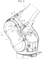
FIG. 2 is a perspective view showing thebase 5, thefirst arm 6, and thesecond arm 7 of the robot 2. As shown inFIG. 2 , the robot 2 has astopper unit 15. Thestopper unit 15 is an example of a restricting member. Thestopper unit 15 is provided on thesecond arm 7. As shown inFIG. 3 as an enlarged view of a part A inFIG. 2 , thestopper unit 15 is locked to thesecond arm 7 by afirst bolt 16 and asecond bolt 17. Thefirst bolt 16 is an example of a first locking member. Thesecond bolt 17 is an example of a second locking member. - The
stopper unit 15 is provided on a surface crossing the second axis J2 of thesecond arm 7. Thestopper unit 15 includes astopper member 18, afirst contact member 19, and asecond contact member 20. Thestopper member 18 is a rod-shaped plate member formed using a metal. Thestopper member 18 is curved in an arc shape as seen along the second axis J2. Thestopper member 18 is along an arc around the second axis J2. Thefirst contact member 19 is provided on one end of the arc-shapedstopper member 18. Thefirst contact member 19 is an example of a contact portion. - The
second contact member 20 is provided on the other end of the arc-shapedstopper member 18. Thefirst contact member 19 and thesecond contact member 20 are respectively formed using hard rubber. When thesecond arm 7 rotates around the second axis J2 and an angle θ1 between thefirst arm 6 and thesecond arm 7 reaches a predetermined angle, thefirst contact member 19 contacts thefirst arm 6. Note that the angle θ1 is an angle between thefirst arm 6 and thesecond arm 7 in a direction from thesecond contact member 20 toward thefirst contact member 19. The direction from thesecond contact member 20 toward thefirst contact member 19 is referred to as "first direction D1". On the other hand, a direction from thefirst contact member 19 toward thesecond contact member 20 is referred to as "second direction D2". Thefirst contact member 19 is located in an end portion of thestopper unit 15 in the first direction D1. Thesecond contact member 20 is located in an end portion of thestopper unit 15 in the second direction D2. - In the
first arm 6, a first receivingportion 21 is provided in a position facing thefirst contact member 19. The first receivingportion 21 is provided in a position that thefirst contact member 19 faces when thesecond arm 7 rotates in the first direction D1. The first receivingportion 21 is provided in a concave shape in thefirst arm 6. As shown inFIG. 4 , when thesecond arm 7 rotates around the second axis J2 in the first direction D1, thefirst contact member 19 of thestopper unit 15 contacts thefirst arm 6 before thesecond arm 7 collides with thefirst arm 6. That is, when thesecond arm 7 rotates around the second axis J2 in the first direction D1, the angle θ1 between thefirst arm 6 and thesecond arm 7 may be restricted by thestopper unit 15. Thereby, a collision between thefirst arm 6 and thesecond arm 7 may be avoided. Note that thefirst contact member 19 of thestopper unit 15 contacts the first receivingportion 21 of thefirst arm 6 shown inFIG. 3 . - As shown in
FIG. 5 , in thefirst arm 6, a second receivingportion 22 is provided in a position facing thesecond contact member 20. Thesecond receiving portion 22 is provided in a position that thesecond contact member 20 faces when thesecond arm 7 rotates in the second direction D2. Thesecond receiving portion 22 is provided in a concave shape in thefirst arm 6. When thesecond arm 7 rotates around the second axis J2 in the second direction D2 and an angle θ2 between thefirst arm 6 and thesecond arm 7 reaches a predetermined angle, thesecond contact member 20 contacts thefirst arm 6. Note that the angle θ2 is an angle between thefirst arm 6 and thesecond arm 7 in the direction from thefirst contact member 19 toward thesecond contact member 20. That is, the the angle θ2 is an angle between thefirst arm 6 and thesecond arm 7 in the second direction D2. - As shown in
FIG. 6 , when thesecond arm 7 rotates around the second axis J2 in the second direction D2, thesecond contact member 20 of thestopper unit 15 contacts thefirst arm 6 before thesecond arm 7 collides with thefirst arm 6. That is, when thesecond arm 7 rotates around the second axis J2 in the second direction D2, the angle θ2 between thefirst arm 6 and thesecond arm 7 may be restricted by thestopper unit 15. Thereby, a collision between thefirst arm 6 and thesecond arm 7 may be avoided. Note that thesecond contact member 20 of thestopper unit 15 contacts the second receivingportion 22 of thefirst arm 6 shown inFIG. 5 . - As shown in
FIG. 7 , a first throughhole 24 and a second throughhole 25 are formed in thestopper member 18. The first throughhole 24 and the second throughhole 25 respectively penetrate thestopper member 18 and reach thesecond arm 7. In thesecond arm 7, afirst screw hole 26 and asecond screw hole 27 are formed. Thefirst screw hole 26 overlaps with the first throughhole 24 when thestopper member 18 and thesecond arm 7 are seen along the second axis J2. Thesecond screw hole 27 overlaps with the second throughhole 25 when thestopper member 18 and thesecond arm 7 are seen along the second axis J2. Thefirst bolt 16 is fastened into thefirst screw hole 26 of thesecond arm 7 through the first throughhole 24 of thestopper member 18. That is, thefirst bolt 16 locks thestopper unit 15 to thesecond arm 7 through the first throughhole 24. - The
second bolt 17 is fastened into thesecond screw hole 27 of thesecond arm 7 through the second throughhole 25 of thestopper member 18. That is, thesecond bolt 17 locks thestopper unit 15 to thesecond arm 7 through the second throughhole 25. When thestopper unit 15 and thesecond arm 7 are seen along the second axis J2, the distance between thefirst contact member 19 and the first throughhole 24 is shorter than the distance between thefirst contact member 19 and the second throughhole 25. That is, the first throughhole 24 is located at one end side of thestopper unit 15 in the first direction D1. On the other hand, the second throughhole 25 is located at the other end side of thestopper unit 15 in the second direction D2. Accordingly, when thestopper unit 15 and thesecond arm 7 are seen along the second axis J2, the distance between thefirst contact member 19 and thefirst bolt 16 is shorter than the distance between thefirst contact member 19 and thesecond bolt 17. - As shown in
FIG. 8 , the first throughhole 24 of thestopper unit 15 is formed in a long hole shape. The long hole shape of the first throughhole 24 is a shape longer than the diameter of thefirst bolt 16 from thefirst bolt 16 toward thefirst contact member 19. According to the robot 2, when thefirst contact member 19 contacts thefirst arm 6, an impact may be relaxed by a friction between thestopper unit 15 and thefirst bolt 16. In other words, when thefirst contact member 19 of thestopper unit 15 contacts thefirst arm 6, an impact force applied to thefirst bolt 16 by thestopper unit 15 may be relaxed. Accordingly, the damage on thefirst arm 6 and thesecond arm 7 may be reduced. - Further, the second through
hole 25 of thestopper unit 15 is formed in a long hole shape. The long hole shape of the second throughhole 25 is a shape longer than the diameter of thesecond bolt 17 from thesecond bolt 17 toward thesecond contact member 20. According to the robot 2, when thesecond contact member 20 contacts thefirst arm 6, the impact may be relaxed by a friction between thestopper unit 15 and thesecond bolt 17. In other words, when thesecond contact member 20 of thestopper unit 15 contacts thefirst arm 6, an impact force applied to thesecond bolt 17 by thestopper unit 15 may be relaxed. Accordingly, the damage on thefirst arm 6 and thesecond arm 7 may be reduced. - As seen from a direction along the second axis J2, as shown in
FIG. 8 , the long hole shape of the first throughhole 24 extends along the first direction D1. According to the configuration, the extension direction of the long hole shape of the first throughhole 24 is easily aligned with a direction of a force acting on thestopper unit 15 when thefirst contact member 19 contacts thefirst arm 6. Accordingly, the impact force applied to thefirst bolt 16 by thestopper unit 15 may be relaxed. Similarly, as seen from the direction along the second axis J2, the long hole shape of the second throughhole 25 extends along the second direction D2. According to the configuration, the extension direction of the long hole shape of the second throughhole 25 is easily aligned with a direction of a force acting on thestopper unit 15 when thesecond contact member 20 contacts thefirst arm 6. Accordingly, the impact force applied to thesecond bolt 17 by thestopper unit 15 may be relaxed. - As seen from the direction along the second axis J2, as shown in
FIG. 8 , the first throughhole 24 has a width dimension H1 in a direction crossing the extension direction of the long hole shape smaller from thefirst bolt 16 toward thefirst contact member 19. When thefirst contact member 19 contacts thefirst arm 6, a force in the second direction D2 is applied to thestopper unit 15 by thefirst arm 6. Accordingly, thestopper unit 15 tends to be displaced in the second direction D2 relative to thesecond arm 7. Concurrently, thefirst bolt 16 may deform thestopper member 18 in a direction in which the width dimension H1 of the first throughhole 24 is increased. Accordingly, the impact force applied to thefirst bolt 16 by thestopper unit 15 may be relaxed. - Similarly, as seen from the direction along the second axis J2, the second through
hole 25 has a width dimension H2 in a direction crossing the extension direction of the long hole shape smaller from thesecond bolt 17 toward thesecond contact member 20. When thesecond contact member 20 contacts thefirst arm 6, a force in the first direction D1 is applied to thestopper unit 15 by thefirst arm 6. Accordingly, thestopper unit 15 tends to be displaced in the first direction D1 relative to thesecond arm 7. Concurrently, thesecond bolt 17 may deform thestopper member 18 in a direction in which the width dimension H2 of the second throughhole 25 is increased. Accordingly, the impact force applied to thesecond bolt 17 by thestopper unit 15 may be relaxed. - In the embodiment, the long sides of the long hole shape of the first through
hole 24 are tapered on both sides. As shown inFIG. 9 as an enlarged view of a part B inFIG. 8 , "tapered on both sides" refers to a state in which both of two long sides of the long hole shape are inclined relative to tangent lines L2. The tangent lines L2 are tangent lines of the first throughhole 24 at intersections between a line segment L1 and the first throughhole 24. The line segment L1 is a straight line passing through the center of thefirst bolt 16 from the position of the second axis J2 and crossing thestopper member 18. Similarly, the long sides of the long hole shape of the second throughhole 25 shown inFIG. 8 are tapered on both sides. - The long sides of the long hole shapes of the first through
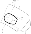
hole 24 and the second throughhole 25 are not limited to those tapered on both sides. As shown inFIG. 10 , the long sides of the long hole shapes of the first throughhole 24 and the second throughhole 25 may be respectively tapered on one sides. "Tapered on one side" refers to a state in which one of the two long sides of the long hole shape is tapered and the other of the long sides extends along the tangent line L2. In "tapered on one side", either of the two long sides of the long hole shape may be tapered. Even when one side of the long sides of the long hole shape is tapered, the same effect as that of "tapered on both sides" may be obtained. Further, the two long sides of the long hole shape are not limited to the straight lines. As shown inFIG. 11 , the two long sides of the long hole shape may be curved lines. A configuration in which one of the two long sides of the long hole shape is a curved line and the other is a straight line may be applied. As the curved line forming the long side, e.g., an arc is applied. Even in a configuration in which at least one of the two long sides of the long hole shape is a curved line, the same effect as that of "tapered on both sides" may be obtained. - As shown in
FIG. 12 , in the embodiment, of parts in which the line segment L1 and thestopper unit 15 overlap, the dimension of afirst part 31 is smaller than the dimension of asecond part 32. As described above, the line segment L1 is the straight line passing through the center of thefirst bolt 16 from the position of the second axis J2 and crossing thestopper member 18. Accordingly, the line segment L1 crosses thestopper unit 15 from the second axis J2 via the first throughhole 24 as seen from the direction along the second axis J2. Thefirst part 31 is a part between the first throughhole 24 and the second axis J2 of the parts in which the line segment L1 and thestopper unit 15 overlap. Thesecond part 32 is a part in a position over the first throughhole 24 from the second axis J2. When the second axis J2 side of the first throughhole 24 is referred to as "inner side", thefirst part 31 is located at the inner side of the first throughhole 24. Thesecond part 32 is located at an outer side of thefirst part 31 as seen from the position of the second axis J2. - When the
first contact member 19 contacts thefirst arm 6, a force is applied to thefirst bolt 16 outward around thesecond bolt 17 as a point of support by thestopper member 18. In the embodiment, the dimension of thefirst part 31 located at the inner side of the first throughhole 24 is smaller than the dimension of thesecond part 32 located at the outer side of the first throughhole 24. In thestopper unit 15, the rigidity of thefirst part 31 is lower than the rigidity of thesecond part 32. According to the configuration, when thefirst bolt 16 deforms thestopper member 18 in a direction in which the width dimension of the first throughhole 24 is increased, the deformation of thefirst part 31 may be made larger than that of thesecond part 32. Accordingly, an impact force applied to thefirst arm 6 outward by thefirst bolt 16 may be relaxed. - In the
stopper unit 15, as shown inFIG. 13 , a configuration having acutout portion 35 may be applied. Thecutout portion 35 is an example of a first cutout portion. Thecutout portion 35 is formed in thestopper member 18. Thecutout portion 35 is formed between the first throughhole 24 and the second throughhole 25. In other words, thecutout portion 35 is formed between thefirst bolt 16 and thesecond bolt 17. According to the configuration, when thefirst contact member 19 of thestopper unit 15 contacts thefirst arm 6, thestopper unit 15 is easily deformed in thecutout portion 35. Therefore, the impact force applied to thefirst bolt 16 by thestopper unit 15 may be relaxed by the deformation in thecutout portion 35. - The
cutout portion 35 is formed at the second axis J2 side of thestopper member 18. Thecutout portion 35 is formed at the second axis J2 side as a rotation center of thesecond arm 7. That is, thecutout portion 35 is formed at the rotation center side of thesecond arm 7. Thecutout portion 35 is formed in an orientation concave outward from the second axis J2 side of thestopper member 18. When thefirst contact member 19 collides with thefirst arm 6, a force is applied to thestopper unit 15 by thefirst arm 6. The force applied to thestopper unit 15 by thefirst arm 6 acts in a direction in which thestopper unit 15 is compressed around thesecond bolt 17 as a point of support. Since thecutout portion 35 is formed at the second axis J2 side of thestopper member 18, thestopper unit 15 is easily bent in thecutout portion 35 around thesecond bolt 17 as a point of support. Therefore, the impact force applied to thefirst bolt 16 by thestopper unit 15 is easily relaxed by the deformation in thecutout portion 35. - In the
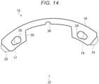
stopper unit 15, as shown inFIG. 14 , a configuration having thecutout portion 35 and asecond cutout portion 36 may be applied. Thecutout portion 35 has the same configuration as that in the example shown inFIG. 13 . Thesecond cutout portion 36 is formed in thestopper member 18. Thesecond cutout portion 36 is formed at an inner side of thecutout portion 35. Thesecond cutout portion 36 is formed in an orientation concave outward from the second axis J2 side at the inner side of thecutout portion 35. According to the configuration, since thecutout portion 35 and thesecond cutout portion 36 are provided, thestopper unit 15 is bent more easily in thecutout portion 35 around thesecond bolt 17 as a point of support. As a result, the impact force applied to thefirst bolt 16 by thestopper unit 15 is more easily relaxed. - In the
stopper unit 15, as shown inFIG. 15 , a configuration having athinner portion 37 as a portion having a smaller thickness may be applied. Thethinner portion 37 is formed in thestopper member 18. Thethinner portion 37 is formed between the first throughhole 24 and the second throughhole 25. In other words, thethinner portion 37 is formed between thefirst bolt 16 and thesecond bolt 17. According to the configuration, when thefirst contact member 19 of thestopper unit 15 contacts thefirst arm 6, thestopper unit 15 is easily deformed in thethinner portion 37. Therefore, the impact force applied to thefirst bolt 16 by thestopper unit 15 may be relaxed by the deformation in thethinner portion 37. - A configuration in which the
thinner portion 37 is formed in thestopper unit 15 having thecutout portion 35 shown inFIG. 13 may be applied. According to the configuration, the impact force applied to thefirst bolt 16 by thestopper unit 15 may be further relaxed by the deformation in thecutout portion 35 and thethinner portion 37. Further, a configuration in which thethinner portion 37 is formed in thestopper unit 15 having thecutout portion 35 and thesecond cutout portion 36 shown inFIG. 14 may be applied. According to the configuration, the impact force applied to thefirst bolt 16 by thestopper unit 15 may be further relaxed by the deformation in thecutout portion 35, thesecond cutout portion 36, and thethinner portion 37. - In the explanation of the
robot system 1, thefirst arm 6 is the example of the first member and thesecond arm 7 is the example of the second member. However, in therobot system 1, thesecond arm 7 may be an example of the first member and thefirst arm 6 may be an example of the second member. In this case, thestopper unit 15 is provided in thefirst arm 6. Further, in this case, the first receivingportion 21 and the second receivingportion 22 are provided in thesecond arm 7. - In the
robot system 1, the configuration in which thestopper unit 15 is provided in thesecond arm 7 is applied. However, a configuration in which thestopper unit 15 is provided in thethird arm 8 may be applied. In this case, thethird arm 8 corresponds to the second member and thesecond arm 7 corresponds to the first member. Further, in this case, the first receivingportion 21 and the second receivingportion 22 are provided in thesecond arm 7. - Furthermore, a configuration in which the
stopper unit 15 is provided in thesecond arm 7 and the first receivingportion 21 and the second receivingportion 22 are provided in thethird arm 8 may be applied. In this case, thethird arm 8 corresponds to the first member and thesecond arm 7 corresponds to the second member. In addition, a configuration in which thestopper units 15 are provided in both thesecond arm 7 and thethird arm 8 may be applied. - The long hole shapes of the first through
hole 24 and the second throughhole 25 may be e.g., oval shapes or rectangular shapes as long as frictions are respectively generated between thestopper unit 15 and thefirst bolt 16 andsecond bolt 17. - Further, the long hole shapes of the first through
hole 24 and the second throughhole 25 may extend along e.g., a tangential direction or a radial direction of a circle around the second axis J2 as long as the long hole shapes extend along directions in which frictions are respectively generated between thestopper unit 15 and thefirst bolt 16 andsecond bolt 17. - The second through
hole 25 may have e.g., a circular shape, not the long hole shape. Further, the second throughhole 25 may be a cutout formed at an end of the plate-like stopper member 18. - Or, the second through
hole 25 is not necessarily formed in thestopper member 18. In this case, the second locking member may be e.g., a hook caught on thestopper member 18, or a structure nipping and holding thestopper member 18. - Or, the first locking member and the second locking member may be pins.
- The robot 2 is not limited to the vertical articulated robot. The robot 2 may be a horizontal articulated robot.
Claims (11)
- A robot comprising:a first member;a second member coupled rotatably around a rotation axis to the first member;a restricting member having a contact portion in contact with the first member when an angle between the first member and the second member is a predetermined angle and a through hole formed therein;a first locking member passing through the through hole and locking the restricting member to the second member; anda second locking member locking the restricting member to the second member, whereinas seen from a direction along the rotation axis,a distance between the contact portion and the first locking member is shorter than a distance between the contact portion and the second locking member, anda length of the through hole in a direction from the first locking member to the contact portion is longer than a diameter of the first locking member.
- The robot according to claim 1, whereinas seen from the direction along the rotation axis,a length of the through hole in a direction along a rotation direction around the rotation axis is longer than the diameter of the first locking member.
- The robot according to claim 2, whereinas seen from the direction along the rotation axis,a width of the through hole in a direction crossing the direction along the rotation direction is smaller from the first locking member toward the contact portion.
- The robot according to claim 3, whereinas seen from the direction along the rotation axis,a shape of a part of the through hole is tapered on one side, tapered on both sides, or an arc shape.
- The robot according to claim 3, whereinas seen from the direction along the rotation axis,when a line segment crossing the restricting member from the rotation axis via the through hole is drawn, of parts in which the line segment and the restricting member overlap, a dimension of a first part between the through hole and the rotation axis is smaller than a dimension of a second part in a position over the through hole from the rotation axis.
- The robot according to claim 1, whereinwith the through hole as a first through hole and the contact portion as a first contact portion,the restricting member has a second contact portion in contact with the first member at an opposite side to the first contact portion and a second through hole formed therein, andthe second locking member locks the restricting member to the second member through the second through hole.
- The robot according to claim 1, wherein
a cutout portion is provided between the first locking member and the second locking member in the restricting member. - The robot according to claim 7, wherein
with the cutout portion as a first cutout portion, a second cutout portion is provided at an inner side of the first cutout portion. - The robot according to claim 7, wherein
the cutout portion is provided at a rotation center side of the second member of the restricting member. - The robot according to claim 1, wherein
the restricting member has a portion having a smaller thickness between the first locking member and the second locking member. - A robot system comprising a robot and a controller controlling the robot, wherein the robot includes:a first member;a second member coupled rotatably around a rotation axis to the first member;a restricting member having a contact portion in contact with the first member when an angle between the first member and the second member is a predetermined angle and a through hole formed therein;a first locking member passing through the through hole and locking the restricting member to the second member; anda second locking member locking the restricting member to the second member, andas seen from a direction along the rotation axis,a distance between the contact portion and the first locking member is shorter than a distance between the contact portion and the second locking member, anda length of the through hole in a direction from the first locking member to the contact portion is longer than a diameter of the first locking member.
Applications Claiming Priority (1)
| Application Number | Priority Date | Filing Date | Title |
|---|---|---|---|
| JP2023042748A JP2024132092A (en) | 2023-03-17 | 2023-03-17 | Robots, Robot Systems |
Publications (2)
| Publication Number | Publication Date |
|---|---|
| EP4431248A1 true EP4431248A1 (en) | 2024-09-18 |
| EP4431248B1 EP4431248B1 (en) | 2025-10-29 |
Family
ID=90361330
Family Applications (1)
| Application Number | Title | Priority Date | Filing Date |
|---|---|---|---|
| EP24161033.6A Active EP4431248B1 (en) | 2023-03-17 | 2024-03-01 | Robot and robot system |
Country Status (4)
| Country | Link |
|---|---|
| US (1) | US20240308090A1 (en) |
| EP (1) | EP4431248B1 (en) |
| JP (1) | JP2024132092A (en) |
| CN (1) | CN118664574A (en) |
Citations (9)
| Publication number | Priority date | Publication date | Assignee | Title |
|---|---|---|---|---|
| JPS60123280A (en) * | 1983-12-02 | 1985-07-01 | オムロン株式会社 | Regulator for motion of body of revolution |
| JPH02160497A (en) * | 1988-12-09 | 1990-06-20 | Yaskawa Electric Mfg Co Ltd | Stopper device |
| JPH11123690A (en) | 1997-10-24 | 1999-05-11 | Denso Corp | Articulated robot |
| JP2007050499A (en) * | 2005-07-21 | 2007-03-01 | Denso Wave Inc | Stopper structure, stopper member fixing structure and stopper member mounting structure |
| JP5360288B2 (en) * | 2012-11-22 | 2013-12-04 | 株式会社デンソーウェーブ | Robot stopper device |
| US20150246450A1 (en) * | 2014-02-28 | 2015-09-03 | Fanuc Corporation | Robot with fixing device for restricting relative rotating motion of two members and such fixing device |
| US20200368895A1 (en) * | 2019-05-24 | 2020-11-26 | Fanuc Corporation | Arm fixing device |
| JP2023006866A (en) * | 2021-06-30 | 2023-01-18 | 株式会社デンソーウェーブ | Mechanical stopper device |
| JP2023042748A (en) | 2021-09-15 | 2023-03-28 | オカモト化成品株式会社 | High-density planting/cultivation apparatus |
-
2023
- 2023-03-17 JP JP2023042748A patent/JP2024132092A/en active Pending
-
2024
- 2024-03-01 EP EP24161033.6A patent/EP4431248B1/en active Active
- 2024-03-15 US US18/605,866 patent/US20240308090A1/en active Pending
- 2024-03-15 CN CN202410300822.5A patent/CN118664574A/en active Pending
Patent Citations (9)
| Publication number | Priority date | Publication date | Assignee | Title |
|---|---|---|---|---|
| JPS60123280A (en) * | 1983-12-02 | 1985-07-01 | オムロン株式会社 | Regulator for motion of body of revolution |
| JPH02160497A (en) * | 1988-12-09 | 1990-06-20 | Yaskawa Electric Mfg Co Ltd | Stopper device |
| JPH11123690A (en) | 1997-10-24 | 1999-05-11 | Denso Corp | Articulated robot |
| JP2007050499A (en) * | 2005-07-21 | 2007-03-01 | Denso Wave Inc | Stopper structure, stopper member fixing structure and stopper member mounting structure |
| JP5360288B2 (en) * | 2012-11-22 | 2013-12-04 | 株式会社デンソーウェーブ | Robot stopper device |
| US20150246450A1 (en) * | 2014-02-28 | 2015-09-03 | Fanuc Corporation | Robot with fixing device for restricting relative rotating motion of two members and such fixing device |
| US20200368895A1 (en) * | 2019-05-24 | 2020-11-26 | Fanuc Corporation | Arm fixing device |
| JP2023006866A (en) * | 2021-06-30 | 2023-01-18 | 株式会社デンソーウェーブ | Mechanical stopper device |
| JP2023042748A (en) | 2021-09-15 | 2023-03-28 | オカモト化成品株式会社 | High-density planting/cultivation apparatus |
Also Published As
| Publication number | Publication date |
|---|---|
| EP4431248B1 (en) | 2025-10-29 |
| JP2024132092A (en) | 2024-09-30 |
| US20240308090A1 (en) | 2024-09-19 |
| CN118664574A (en) | 2024-09-20 |
Similar Documents
| Publication | Publication Date | Title |
|---|---|---|
| US8003916B2 (en) | Industrial robot | |
| CN110293540B (en) | Robot | |
| EP2998081B1 (en) | Link actuation device | |
| JP5231760B2 (en) | Clamp | |
| CN105690418B (en) | tool adapter and robot | |
| CN118700185A (en) | Arm assembly and humanoid robot | |
| US20240308090A1 (en) | Robot and robot system | |
| US12109696B2 (en) | Stopper structure and articulated robot | |
| JP4412308B2 (en) | Stopper structure and stopper member mounting structure | |
| US20200368895A1 (en) | Arm fixing device | |
| JP2020179483A (en) | robot | |
| JP7648898B2 (en) | Mechanical Stopper Device | |
| JP2024029474A (en) | Stopper structure and articulated robot | |
| CN220051900U (en) | Limiting device, robot joint and robot | |
| JPH01135487A (en) | Rotary stroke regulator for shaft | |
| KR102549560B1 (en) | Joint device | |
| CN117140490B (en) | Manipulator assembly and manipulator | |
| WO2023119501A1 (en) | Moving mechanism stopping device, and robot | |
| CN120680553A (en) | Joint components and robots | |
| TWM681040U (en) | Positioning mechanism | |
| KR20250138302A (en) | Electronic brake system | |
| JPS629037Y2 (en) | ||
| CN121403456A (en) | Locking device, mechanical finger and robotic arm | |
| JPH07208522A (en) | Stopper device for turning shaft | |
| WO2025105023A1 (en) | Torque sensor |
Legal Events
| Date | Code | Title | Description |
|---|---|---|---|
| PUAI | Public reference made under article 153(3) epc to a published international application that has entered the european phase |
Free format text: ORIGINAL CODE: 0009012 |
|
| STAA | Information on the status of an ep patent application or granted ep patent |
Free format text: STATUS: THE APPLICATION HAS BEEN PUBLISHED |
|
| AK | Designated contracting states |
Kind code of ref document: A1 Designated state(s): AL AT BE BG CH CY CZ DE DK EE ES FI FR GB GR HR HU IE IS IT LI LT LU LV MC ME MK MT NL NO PL PT RO RS SE SI SK SM TR |
|
| STAA | Information on the status of an ep patent application or granted ep patent |
Free format text: STATUS: REQUEST FOR EXAMINATION WAS MADE |
|
| 17P | Request for examination filed |
Effective date: 20250318 |
|
| GRAP | Despatch of communication of intention to grant a patent |
Free format text: ORIGINAL CODE: EPIDOSNIGR1 |
|
| STAA | Information on the status of an ep patent application or granted ep patent |
Free format text: STATUS: GRANT OF PATENT IS INTENDED |
|
| INTG | Intention to grant announced |
Effective date: 20250528 |
|
| GRAS | Grant fee paid |
Free format text: ORIGINAL CODE: EPIDOSNIGR3 |
|
| GRAA | (expected) grant |
Free format text: ORIGINAL CODE: 0009210 |
|
| STAA | Information on the status of an ep patent application or granted ep patent |
Free format text: STATUS: THE PATENT HAS BEEN GRANTED |
|
| AK | Designated contracting states |
Kind code of ref document: B1 Designated state(s): AL AT BE BG CH CY CZ DE DK EE ES FI FR GB GR HR HU IE IS IT LI LT LU LV MC ME MK MT NL NO PL PT RO RS SE SI SK SM TR |
|
| REG | Reference to a national code |
Ref country code: CH Ref legal event code: F10 Free format text: ST27 STATUS EVENT CODE: U-0-0-F10-F00 (AS PROVIDED BY THE NATIONAL OFFICE) Effective date: 20251029 Ref country code: GB Ref legal event code: FG4D |
|
| REG | Reference to a national code |
Ref country code: DE Ref legal event code: R096 Ref document number: 602024001050 Country of ref document: DE |
|
| REG | Reference to a national code |
Ref country code: IE Ref legal event code: FG4D |
|
| REG | Reference to a national code |
Ref country code: NL Ref legal event code: MP Effective date: 20251029 |
|
| PG25 | Lapsed in a contracting state [announced via postgrant information from national office to epo] |
Ref country code: ES Free format text: LAPSE BECAUSE OF FAILURE TO SUBMIT A TRANSLATION OF THE DESCRIPTION OR TO PAY THE FEE WITHIN THE PRESCRIBED TIME-LIMIT Effective date: 20251029 |
|
| REG | Reference to a national code |
Ref country code: LT Ref legal event code: MG9D |
|
| PG25 | Lapsed in a contracting state [announced via postgrant information from national office to epo] |
Ref country code: NO Free format text: LAPSE BECAUSE OF FAILURE TO SUBMIT A TRANSLATION OF THE DESCRIPTION OR TO PAY THE FEE WITHIN THE PRESCRIBED TIME-LIMIT Effective date: 20260129 |
|
| PGFP | Annual fee paid to national office [announced via postgrant information from national office to epo] |
Ref country code: DE Payment date: 20260331 Year of fee payment: 3 |
|
| PG25 | Lapsed in a contracting state [announced via postgrant information from national office to epo] |
Ref country code: AT Free format text: LAPSE BECAUSE OF FAILURE TO SUBMIT A TRANSLATION OF THE DESCRIPTION OR TO PAY THE FEE WITHIN THE PRESCRIBED TIME-LIMIT Effective date: 20251029 Ref country code: FI Free format text: LAPSE BECAUSE OF FAILURE TO SUBMIT A TRANSLATION OF THE DESCRIPTION OR TO PAY THE FEE WITHIN THE PRESCRIBED TIME-LIMIT Effective date: 20251029 Ref country code: HR Free format text: LAPSE BECAUSE OF FAILURE TO SUBMIT A TRANSLATION OF THE DESCRIPTION OR TO PAY THE FEE WITHIN THE PRESCRIBED TIME-LIMIT Effective date: 20251029 |
|
| PGFP | Annual fee paid to national office [announced via postgrant information from national office to epo] |
Ref country code: AT Payment date: 20260301 Year of fee payment: 3 |
|
| REG | Reference to a national code |
Ref country code: AT Ref legal event code: MK05 Ref document number: 1851079 Country of ref document: AT Kind code of ref document: T Effective date: 20251029 |
|
| PG25 | Lapsed in a contracting state [announced via postgrant information from national office to epo] |
Ref country code: NL Free format text: LAPSE BECAUSE OF FAILURE TO SUBMIT A TRANSLATION OF THE DESCRIPTION OR TO PAY THE FEE WITHIN THE PRESCRIBED TIME-LIMIT Effective date: 20251029 |
|
| PG25 | Lapsed in a contracting state [announced via postgrant information from national office to epo] |
Ref country code: RS Free format text: LAPSE BECAUSE OF FAILURE TO SUBMIT A TRANSLATION OF THE DESCRIPTION OR TO PAY THE FEE WITHIN THE PRESCRIBED TIME-LIMIT Effective date: 20260129 |
|
| PG25 | Lapsed in a contracting state [announced via postgrant information from national office to epo] |
Ref country code: IS Free format text: LAPSE BECAUSE OF FAILURE TO SUBMIT A TRANSLATION OF THE DESCRIPTION OR TO PAY THE FEE WITHIN THE PRESCRIBED TIME-LIMIT Effective date: 20260228 |
|
| PG25 | Lapsed in a contracting state [announced via postgrant information from national office to epo] |
Ref country code: PT Free format text: LAPSE BECAUSE OF FAILURE TO SUBMIT A TRANSLATION OF THE DESCRIPTION OR TO PAY THE FEE WITHIN THE PRESCRIBED TIME-LIMIT Effective date: 20260302 |
|
| PG25 | Lapsed in a contracting state [announced via postgrant information from national office to epo] |
Ref country code: PL Free format text: LAPSE BECAUSE OF FAILURE TO SUBMIT A TRANSLATION OF THE DESCRIPTION OR TO PAY THE FEE WITHIN THE PRESCRIBED TIME-LIMIT Effective date: 20251029 |
|
| PG25 | Lapsed in a contracting state [announced via postgrant information from national office to epo] |
Ref country code: LV Free format text: LAPSE BECAUSE OF FAILURE TO SUBMIT A TRANSLATION OF THE DESCRIPTION OR TO PAY THE FEE WITHIN THE PRESCRIBED TIME-LIMIT Effective date: 20251029 |
|
| PG25 | Lapsed in a contracting state [announced via postgrant information from national office to epo] |
Ref country code: BG Free format text: LAPSE BECAUSE OF FAILURE TO SUBMIT A TRANSLATION OF THE DESCRIPTION OR TO PAY THE FEE WITHIN THE PRESCRIBED TIME-LIMIT Effective date: 20251029 |