EP4431227A1 - Spindles peening offset fixture for cnc turning - Google Patents
Spindles peening offset fixture for cnc turning Download PDFInfo
- Publication number
- EP4431227A1 EP4431227A1 EP24162680.3A EP24162680A EP4431227A1 EP 4431227 A1 EP4431227 A1 EP 4431227A1 EP 24162680 A EP24162680 A EP 24162680A EP 4431227 A1 EP4431227 A1 EP 4431227A1
- Authority
- EP
- European Patent Office
- Prior art keywords
- fixture
- arm
- airfoil
- vane
- upper portion
- Prior art date
- Legal status (The legal status is an assumption and is not a legal conclusion. Google has not performed a legal analysis and makes no representation as to the accuracy of the status listed.)
- Pending
Links
Images



Classifications
-
- B—PERFORMING OPERATIONS; TRANSPORTING
- B23—MACHINE TOOLS; METAL-WORKING NOT OTHERWISE PROVIDED FOR
- B23B—TURNING; BORING
- B23B25/00—Accessories or auxiliary equipment for turning-machines
-
- B—PERFORMING OPERATIONS; TRANSPORTING
- B23—MACHINE TOOLS; METAL-WORKING NOT OTHERWISE PROVIDED FOR
- B23P—METAL-WORKING NOT OTHERWISE PROVIDED FOR; COMBINED OPERATIONS; UNIVERSAL MACHINE TOOLS
- B23P15/00—Making specific metal objects by operations not covered by a single other subclass or a group in this subclass
- B23P15/02—Making specific metal objects by operations not covered by a single other subclass or a group in this subclass turbine or like blades from one piece
-
- B—PERFORMING OPERATIONS; TRANSPORTING
- B25—HAND TOOLS; PORTABLE POWER-DRIVEN TOOLS; MANIPULATORS
- B25B—TOOLS OR BENCH DEVICES NOT OTHERWISE PROVIDED FOR, FOR FASTENING, CONNECTING, DISENGAGING, OR HOLDING
- B25B11/00—Work holders not covered by any preceding group in the subclass, e.g. magnetic work holders, vacuum work holders
-
- B—PERFORMING OPERATIONS; TRANSPORTING
- B23—MACHINE TOOLS; METAL-WORKING NOT OTHERWISE PROVIDED FOR
- B23B—TURNING; BORING
- B23B2215/00—Details of workpieces
- B23B2215/76—Components for turbines
- B23B2215/81—Turbine blades
-
- B—PERFORMING OPERATIONS; TRANSPORTING
- B23—MACHINE TOOLS; METAL-WORKING NOT OTHERWISE PROVIDED FOR
- B23P—METAL-WORKING NOT OTHERWISE PROVIDED FOR; COMBINED OPERATIONS; UNIVERSAL MACHINE TOOLS
- B23P25/00—Auxiliary treatment of workpieces, before or during machining operations, to facilitate the action of the tool or the attainment of a desired final condition of the work, e.g. relief of internal stress
-
- B—PERFORMING OPERATIONS; TRANSPORTING
- B23—MACHINE TOOLS; METAL-WORKING NOT OTHERWISE PROVIDED FOR
- B23Q—DETAILS, COMPONENTS, OR ACCESSORIES FOR MACHINE TOOLS, e.g. ARRANGEMENTS FOR COPYING OR CONTROLLING; MACHINE TOOLS IN GENERAL CHARACTERISED BY THE CONSTRUCTION OF PARTICULAR DETAILS OR COMPONENTS; COMBINATIONS OR ASSOCIATIONS OF METAL-WORKING MACHINES, NOT DIRECTED TO A PARTICULAR RESULT
- B23Q3/00—Devices holding, supporting, or positioning work or tools, of a kind normally removable from the machine
- B23Q3/02—Devices holding, supporting, or positioning work or tools, of a kind normally removable from the machine for mounting on a work-table, tool-slide, or analogous part
- B23Q3/06—Work-clamping means
- B23Q3/062—Work-clamping means adapted for holding workpieces having a special form or being made from a special material
- B23Q3/063—Work-clamping means adapted for holding workpieces having a special form or being made from a special material for holding turbine blades
-
- F—MECHANICAL ENGINEERING; LIGHTING; HEATING; WEAPONS; BLASTING
- F01—MACHINES OR ENGINES IN GENERAL; ENGINE PLANTS IN GENERAL; STEAM ENGINES
- F01D—NON-POSITIVE DISPLACEMENT MACHINES OR ENGINES, e.g. STEAM TURBINES
- F01D17/00—Regulating or controlling by varying flow
- F01D17/10—Final actuators
- F01D17/12—Final actuators arranged in stator parts
- F01D17/14—Final actuators arranged in stator parts varying effective cross-sectional area of nozzles or guide conduits
- F01D17/16—Final actuators arranged in stator parts varying effective cross-sectional area of nozzles or guide conduits by means of nozzle vanes
- F01D17/162—Final actuators arranged in stator parts varying effective cross-sectional area of nozzles or guide conduits by means of nozzle vanes for axial flow, i.e. the vanes turning around axes which are essentially perpendicular to the rotor centre line
Definitions
- the present disclosure is directed to the relative positions of spindle/trunnion surfaces on spindle vanes after post processing operations.
- a fixture is configured to account for the offset on spindles caused by stress relief and peening processing.
- the general process flow for milling a compressor spindle vane includes operations that are the primary drivers for the dimensional requirements of the spindles, buttons, and the airfoil.
- an oversized forging is loaded into a mill turn CNC to turn the spindles.
- a 5-axis CNC is employed to mill the airfoil.
- the part goes through a variety of finishing operations. Most of the finishing operations have a negligible effect on the dimensional requirements except for airfoil peening. Airfoil peening has been shown to significantly change the overall shape of the part via bowing. After all finishing operations are done, the part is inspected for airfoil and spindle dimensions.
- the problem to be solved includes the relative positions of spindle/trunnion surfaces on spindle vanes after post processing operations.
- the relative position of the ID spindle to the OD spindle shifts through finishing operations such as airfoil peening and is the main driver for cost of poor quality on spindle vanes.
- peening will always cause some distortion to an extent, and the process is now thought to have distortion minimized as best possible for production.
- the peening distortion amount is still causing the majority of dimensional nonconformances for spindle vanes.
- the focus has shifted to the CNC turning operation to find ways to offset for peening distortions.
- Fig. 1 showing the spindles S being aligned on the same axis
- Fig. 2 showing the spindles S being distorted relative to each other and being nonconforming.
- the relative position of the inner diameter (ID) spindle to the outer diameter (CD) spindle moves through post turning operations such as stress relief and airfoil peening. It is anticipated that spindle tolerances will become more restrictive in the future. It is known that airfoil peening will be required on compressor airfoils, and airfoil peening will distort an airfoil to at least some degree.
- the solution is to find a way to offset a part at the turning operation to account for peening distortion.
- a turning fixture comprising a fixture insert attached to the turning fixture, the fixture insert comprising an upper portion having an upper portion body, the upper portion body includes a central span with a first arm and second arm opposite the first arm, a cavity is defined between the first arm and the second arm along the central span on an inner side of the upper portion body; the fixture insert including a lower portion having a lower portion body that includes a chamber located centrally between a first end and a second end; and a rod is insertable through the lower portion through the chamber, the rod being configured to apply a force to a compressor spindle vane inserted between the upper portion and the lower portion.
- Particular embodiments may include at least on, or a plurality of, the following optional features. These feature may be present separately, or in combination with reach other, unless indicated otherwise.
- a further embodiment of any of the foregoing embodiments may additionally and/or alternatively include the cavity is sized to allow for an airfoil of the compressor spindle vane to deflect without impinging on the inner side.
- a further embodiment of any of the foregoing embodiments may additionally and/or alternatively include the lower portion body is configured to contact the airfoil opposite the first arm and the second arm of the upper portion.
- a further embodiment of any of the foregoing embodiments may additionally and/or alternatively include the lower portion body is configured to contact the airfoil along a length of the airfoil minus a chamber width.
- a further embodiment of any of the foregoing embodiments may additionally and/or alternatively include the rod is configured to translate through the chamber for impingement on the airfoil and to apply the force that deflects the airfoil toward the cavity.
- a further embodiment of any of the foregoing embodiments may additionally and/or alternatively include the upper portion is configured to press against the airfoil with both the first arm and the second arm proximate filets of each of the spindles.
- a further embodiment of any of the foregoing embodiments may additionally and/or alternatively include the rod is configured to press against the airfoil on an opposite side of the airfoil from the first arm and the second arm.
- a turning fixture for machining a compressor spindle vane comprising a fixture insert attached to the turning fixture, the fixture insert comprising an upper portion having an upper portion body, the upper portion body includes a central span with a first arm and second arm opposite the first arm, a cavity is defined between the first arm and the second arm along the central span on an inner side of the upper portion body; the fixture insert including a lower portion having a lower portion body that includes a chamber located centrally between a first end and a second end; and a rod is insertable through the lower portion through the chamber, the rod being configured to apply a force to an airfoil of the compressor spindle vane inserted between the upper portion and the lower portion.
- a further embodiment of any of the foregoing embodiments may additionally and/or alternatively include the cavity is sized for deflection of the airfoil of the compressor spindle vane in the absence of impingement on the inner side.
- Particular embodiments may include at least on, or a plurality of, the following optional features. These feature may be present separately, or in combination with reach other, unless indicated otherwise.
- a further embodiment of any of the foregoing embodiments may additionally and/or alternatively include the lower portion body is configured to contact the airfoil opposite the first arm and the second arm of the upper portion.
- a further embodiment of any of the foregoing embodiments may additionally and/or alternatively include the rod is configured to translate through the chamber for impingement on the airfoil and to apply the force that deflects the airfoil toward the cavity.
- a further embodiment of any of the foregoing embodiments may additionally and/or alternatively include the force applied by the rod is configured to distort the compressor spindle vane in an equal and opposite amount of a predetermined distortion defined by a subsequent finishing operation.
- a further embodiment of any of the foregoing embodiments may additionally and/or alternatively include the fixture insert is interchangeable in the turning fixture and configured to be replaced by another fixture insert configured for a particular design.
- a process for distorting a compressor spindle vane mounted in a turning fixture comprising inserting the compressor spindle vane into a fixture insert attached the turning fixture between an upper portion and a lower portion; forcing a rod against an airfoil of the compressor spindle vane toward a cavity formed in the upper portion; and creating an offset in the compressor spindle vane.
- a further embodiment of any of the foregoing embodiments may additionally and/or alternatively include the upper portion body includes a central span with a first arm and a second arm opposite the first arm; the cavity being defined between the first arm and the second arm along the central span on an inner side of the upper portion body proximate to the compressor spindle vane.
- Particular embodiments may include at least on, or a plurality of, the following optional features. These feature may be present separately, or in combination with reach other, unless indicated otherwise.
- a further embodiment of any of the foregoing embodiments may additionally and/or alternatively include the lower portion includes a lower portion body that includes a chamber located centrally between a first end and a second end; and the rod is insertable through the lower portion through the chamber.
- a further embodiment of any of the foregoing embodiments may additionally and/or alternatively include the compressor spindle vane offset is in an equal and opposite amount of a predetermined distortion defined by subsequent finishing operation.
- a further embodiment of any of the foregoing embodiments may additionally and/or alternatively include the offset is a distortion defined by an angle of deflection from a central axis of the compressor spindle vane.
- a further embodiment of any of the foregoing embodiments may additionally and/or alternatively include the process further comprising at least one of: removing the fixture insert from the turning fixture; and inserting the fixture insert in the turning fixture; and replacing the fixture insert with another fixture insert configured for a particular design.
- a further embodiment of any of the foregoing embodiments may additionally and/or alternatively include the process further comprising controlling an amount of angle offset on spindles of the compressor spindle vane in the fixture with a zero out dial indicator.
- the disclosed process can offset for the distortion that happens through post processing and still use the capability of turning both spindles on the same axis in a CNC lathe.
- the intent of the disclosed process is to focus on spindle turn, airfoil peen, and spindle inspection.
- the goal is to have conforming spindles at spindle inspection.
- the current process attempts to minimize distortion caused during peening, however, minimizing the distortion is not adequate.
- the disclosed process accounts for distortion at spindle turn by offsetting the spindles, so the inherent and controlled distortion caused by peening will 'correct' the spindles thus yielding a conforming part.
- the fixture insert 10 are configured to go into a standard turning fixture 12 (shown schematically).
- the fixture insert 10 are configured to support a compressor spindle vane 14.
- the fixture insert 10 can be utilized to support the compressor spindle vane 14 during a spindle turn operation.
- the fixture insert 10 includes an upper portion 16 and a lower portion 18.
- the upper portion 16 includes an upper portion body 20.
- the upper portion body 20 includes a central span 22 with a first arm 24 and second arm 26 opposite the first arm 24.
- a cavity 28 is defined between the first arm 24 and second arm 26 along the central span 22 on an inner side 30 of the upper portion body 20 proximate to the compressor spindle vane 14.
- the cavity 28 is sized to allow sufficient space for the airfoil A of the compressor spindle vane 14 to deflect without impinging on the inner side 30.
- the lower portion 18 includes a lower portion body 32.
- the lower portion body 32 includes a chamber 34 located centrally between a first end 36 and a second end 38.
- the lower portion body 32 contacts the airfoil A opposite the first arm 24 and the second arm 26 of the upper portion 16, as well as along the length of the airfoil A.
- the chamber 34 does not contact the airfoil A along the width of the chamber 34.
- the chamber 34 receives a rod 40 that translates through the chamber 34 for impingement on the airfoil A.
- the rod 40 is configured to press against the airfoil A and apply a deflection force that deflects the airfoil A toward the cavity 28.
- the upper portion 16 is configured to press against the airfoil A with each of the first arm 24 and the second arm 26 proximate each of filets of the spindles 42 44.
- the rod 40 is configured to press against the airfoil A at approximately a central portion 46 of the airfoil A.
- the rod 40 is configured to press against the airfoil on an opposite side of the airfoil A from the arms 24, 26.
- the schematic representation of the translation of the rod 40 pressing against the airfoil A at a central portion 46 distorts the compressor spindle vane part 14 to create an offset 48 from a central axis C.
- the offset 48 can be defined by an angle of deflection 50.
- the offset 48 is configured to match the anticipated distortion that will be created by the peening processing.
- the turning fixture 12 with fixture inserts 10 and rod 40 apply sufficient force on the pre-machined airfoil A during the turning operation to distort the compressor spindle vane part 14 in an equal and opposite amount of the distortion that the subsequent peening operation will have on the compressor spindle vane part 14.
- the fixture insert 10 is insertable and can be customized for particular compressor spindle vane parts 14, such that the fixture insert 10 can be swapped out for another fixture insert 10 for particular designs during changeover.
- the fixture insert 10 can be matched to particular part 14 design to achieve the required offset on the spindles 42, 44.
- a dial indicator (not shown) can be used to obtain the predetermined offset on the part 14 during the turning process.
- the amount of angle offset 48 on the spindles 42, 44 while loading in the fixture 12 can be controlled with the zero out dial indicator.
- the fixture inserts 10 can be designed for applying the pressure to points along the airfoil A in order to achieve the required offsets on the spindles 42, 44.
- the fixture 12 with fixture insert 10 can be targeted for manufacturing target dimensions for the spindles 14 which should allow for conforming to blueprint dimensions at a final spindle inspection.
- An actuator 52 is in operative communication with the rod 40.
- the actuator 52 is configured to move the rod 40 for the application of the forces to deflect the airfoil A.
- the process 100 includes a step 102 of assembling the fixture insert into the standard turning fixture.
- the step 104 includes inserting the compressor spindle vane into the fixture insert.
- the step 106 includes applying forces to distort the compressor spindle vane.
- the step 108 includes machining the spindles.
- the step 110 includes removing the compressor spindle from the fixture and process through finishing operations.
- a technical advantage of the disclosed fixturing process and fixture includes producing an offset on a part at the turning operation to account for peening distortion to give manufacturing better process control and capability.
- fixturing process and fixture includes the capacity to change the fixture along with a new control plan to allow for manufacturing operations to target for a predetermined amount of offset by applying more or less force to the compressor spindle vane, and while avoiding capitol expense for downstream processing.
- fixturing process and fixture includes the capacity to have greater process control and capability because manufacturing process can turn the part with distortion added to account for the inherent distortion caused by finishing operations.
- Another technical advantage of the disclosed fixturing process and fixture includes the capacity to design a process that accounts for the known finishing distortions.
- fixturing process and fixture includes a fixture that enables control over the process at the machining level instead of reacting to a widely known condition after the part is over 90% complete.
- fixturing process and fixture includes a fixturing process that allows one to fix the spindle relative position issue during manufacturing of the compressor spindle vane to reduce cost of poor quality, improve engine performance and limit wear issues in the field.
Landscapes
- Engineering & Computer Science (AREA)
- Mechanical Engineering (AREA)
- Structures Of Non-Positive Displacement Pumps (AREA)
Abstract
A turning fixture including a fixture insert attached to the turning fixture, the fixture insert comprising an upper portion having an upper portion body, the upper portion body includes a central span with a first arm and second arm opposite the first arm, a cavity is defined between the first arm and the second arm along the central span on an inner side of the upper portion body; the fixture insert including a lower portion having a lower portion body that includes a chamber located centrally between a first end and a second end; and a rod is insertable through the lower portion through the chamber, the rod being configured to apply a force to a compressor spindle vane inserted between the upper portion and the lower portion.
Description
- The present disclosure is directed to the relative positions of spindle/trunnion surfaces on spindle vanes after post processing operations. Particularly a fixture is configured to account for the offset on spindles caused by stress relief and peening processing.
- The general process flow for milling a compressor spindle vane includes operations that are the primary drivers for the dimensional requirements of the spindles, buttons, and the airfoil. For a mill process, an oversized forging is loaded into a mill turn CNC to turn the spindles. Then a 5-axis CNC is employed to mill the airfoil. From there, the part goes through a variety of finishing operations. Most of the finishing operations have a negligible effect on the dimensional requirements except for airfoil peening. Airfoil peening has been shown to significantly change the overall shape of the part via bowing. After all finishing operations are done, the part is inspected for airfoil and spindle dimensions.
- The problem to be solved includes the relative positions of spindle/trunnion surfaces on spindle vanes after post processing operations. The relative position of the ID spindle to the OD spindle shifts through finishing operations such as airfoil peening and is the main driver for cost of poor quality on spindle vanes.
- Historically, the problem was thought to be the airfoil peening operation, thus the engineering focus to solve the problem has been on the peening process. Through the heightened focus on the peening operation, peening has become highly controlled and repeatable while also minimizing the amount of distortion caused by peening.
- However, peening will always cause some distortion to an extent, and the process is now thought to have distortion minimized as best possible for production. The peening distortion amount is still causing the majority of dimensional nonconformances for spindle vanes. The focus has shifted to the CNC turning operation to find ways to offset for peening distortions.
- As seen by the contrast of
Fig. 1 showing the spindles S being aligned on the same axis andFig. 2 showing the spindles S being distorted relative to each other and being nonconforming. The relative position of the inner diameter (ID) spindle to the outer diameter (CD) spindle moves through post turning operations such as stress relief and airfoil peening. It is anticipated that spindle tolerances will become more restrictive in the future. It is known that airfoil peening will be required on compressor airfoils, and airfoil peening will distort an airfoil to at least some degree. - The solution is to find a way to offset a part at the turning operation to account for peening distortion.
- In accordance with the present disclosure, there is provided a turning fixture comprising a fixture insert attached to the turning fixture, the fixture insert comprising an upper portion having an upper portion body, the upper portion body includes a central span with a first arm and second arm opposite the first arm, a cavity is defined between the first arm and the second arm along the central span on an inner side of the upper portion body; the fixture insert including a lower portion having a lower portion body that includes a chamber located centrally between a first end and a second end; and a rod is insertable through the lower portion through the chamber, the rod being configured to apply a force to a compressor spindle vane inserted between the upper portion and the lower portion.
- Particular embodiments may include at least on, or a plurality of, the following optional features. These feature may be present separately, or in combination with reach other, unless indicated otherwise.
- A further embodiment of any of the foregoing embodiments may additionally and/or alternatively include the cavity is sized to allow for an airfoil of the compressor spindle vane to deflect without impinging on the inner side.
- A further embodiment of any of the foregoing embodiments may additionally and/or alternatively include the lower portion body is configured to contact the airfoil opposite the first arm and the second arm of the upper portion.
- A further embodiment of any of the foregoing embodiments may additionally and/or alternatively include the lower portion body is configured to contact the airfoil along a length of the airfoil minus a chamber width.
- A further embodiment of any of the foregoing embodiments may additionally and/or alternatively include the rod is configured to translate through the chamber for impingement on the airfoil and to apply the force that deflects the airfoil toward the cavity.
- A further embodiment of any of the foregoing embodiments may additionally and/or alternatively include the upper portion is configured to press against the airfoil with both the first arm and the second arm proximate filets of each of the spindles.
- A further embodiment of any of the foregoing embodiments may additionally and/or alternatively include the rod is configured to press against the airfoil on an opposite side of the airfoil from the first arm and the second arm.
- In accordance with the present disclosure, there is provided a turning fixture for machining a compressor spindle vane comprising a fixture insert attached to the turning fixture, the fixture insert comprising an upper portion having an upper portion body, the upper portion body includes a central span with a first arm and second arm opposite the first arm, a cavity is defined between the first arm and the second arm along the central span on an inner side of the upper portion body; the fixture insert including a lower portion having a lower portion body that includes a chamber located centrally between a first end and a second end; and a rod is insertable through the lower portion through the chamber, the rod being configured to apply a force to an airfoil of the compressor spindle vane inserted between the upper portion and the lower portion.
- A further embodiment of any of the foregoing embodiments may additionally and/or alternatively include the cavity is sized for deflection of the airfoil of the compressor spindle vane in the absence of impingement on the inner side.
- Particular embodiments may include at least on, or a plurality of, the following optional features. These feature may be present separately, or in combination with reach other, unless indicated otherwise.
- A further embodiment of any of the foregoing embodiments may additionally and/or alternatively include the lower portion body is configured to contact the airfoil opposite the first arm and the second arm of the upper portion.
- A further embodiment of any of the foregoing embodiments may additionally and/or alternatively include the rod is configured to translate through the chamber for impingement on the airfoil and to apply the force that deflects the airfoil toward the cavity.
- A further embodiment of any of the foregoing embodiments may additionally and/or alternatively include the force applied by the rod is configured to distort the compressor spindle vane in an equal and opposite amount of a predetermined distortion defined by a subsequent finishing operation.
- A further embodiment of any of the foregoing embodiments may additionally and/or alternatively include the fixture insert is interchangeable in the turning fixture and configured to be replaced by another fixture insert configured for a particular design.
- In accordance with the present disclosure, there is provided a process for distorting a compressor spindle vane mounted in a turning fixture comprising inserting the compressor spindle vane into a fixture insert attached the turning fixture between an upper portion and a lower portion; forcing a rod against an airfoil of the compressor spindle vane toward a cavity formed in the upper portion; and creating an offset in the compressor spindle vane.
- A further embodiment of any of the foregoing embodiments may additionally and/or alternatively include the upper portion body includes a central span with a first arm and a second arm opposite the first arm; the cavity being defined between the first arm and the second arm along the central span on an inner side of the upper portion body proximate to the compressor spindle vane.
- Particular embodiments may include at least on, or a plurality of, the following optional features. These feature may be present separately, or in combination with reach other, unless indicated otherwise.
- A further embodiment of any of the foregoing embodiments may additionally and/or alternatively include the lower portion includes a lower portion body that includes a chamber located centrally between a first end and a second end; and the rod is insertable through the lower portion through the chamber.
- A further embodiment of any of the foregoing embodiments may additionally and/or alternatively include the compressor spindle vane offset is in an equal and opposite amount of a predetermined distortion defined by subsequent finishing operation.
- A further embodiment of any of the foregoing embodiments may additionally and/or alternatively include the offset is a distortion defined by an angle of deflection from a central axis of the compressor spindle vane.
- A further embodiment of any of the foregoing embodiments may additionally and/or alternatively include the process further comprising at least one of: removing the fixture insert from the turning fixture; and inserting the fixture insert in the turning fixture; and replacing the fixture insert with another fixture insert configured for a particular design.
- A further embodiment of any of the foregoing embodiments may additionally and/or alternatively include the process further comprising controlling an amount of angle offset on spindles of the compressor spindle vane in the fixture with a zero out dial indicator.
- The disclosed process can offset for the distortion that happens through post processing and still use the capability of turning both spindles on the same axis in a CNC lathe.
- The intent of the disclosed process is to focus on spindle turn, airfoil peen, and spindle inspection. The goal is to have conforming spindles at spindle inspection. The current process attempts to minimize distortion caused during peening, however, minimizing the distortion is not adequate. Whereas the disclosed process accounts for distortion at spindle turn by offsetting the spindles, so the inherent and controlled distortion caused by peening will 'correct' the spindles thus yielding a conforming part.
- Other details of the disclosed process and fixture are set forth in the following detailed description and the accompanying drawings wherein like reference numerals depict like elements.
-
Fig. 1 is a schematic representation of an exemplary conforming spindle. -
Fig. 2 is a schematic representation of an exemplary nonconforming spindle. -
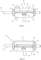
Fig. 3 is a front view schematic representation of an exemplary fixture. -
Fig. 4 is an isometric view schematic representation of the exemplary fixture. -
Fig. 5 is a front view schematic of the exemplary fixture engaging a part. -
Fig. 6 is an isometric view schematic of the exemplary fixture engaging a part. -
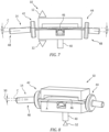
Fig. 7 is a front view schematic of the exemplary fixture engaged on a part with shape change. -
Fig. 8 is a front view schematic of the exemplary fixture engaged on a part with shape change. -
Fig. 9 is a process map of the exemplary process. - Referring to
Fig. 3 and Fig 4 , there is illustratedexemplary fixture insert 10. Thefixture insert 10 are configured to go into a standard turning fixture 12 (shown schematically). Thefixture insert 10 are configured to support acompressor spindle vane 14. Thefixture insert 10 can be utilized to support thecompressor spindle vane 14 during a spindle turn operation. Thefixture insert 10 includes anupper portion 16 and alower portion 18. - The
upper portion 16 includes anupper portion body 20. Theupper portion body 20 includes acentral span 22 with afirst arm 24 andsecond arm 26 opposite thefirst arm 24. Acavity 28 is defined between thefirst arm 24 andsecond arm 26 along thecentral span 22 on aninner side 30 of theupper portion body 20 proximate to thecompressor spindle vane 14. Thecavity 28 is sized to allow sufficient space for the airfoil A of thecompressor spindle vane 14 to deflect without impinging on theinner side 30. - The
lower portion 18 includes alower portion body 32. Thelower portion body 32 includes achamber 34 located centrally between afirst end 36 and asecond end 38. Thelower portion body 32 contacts the airfoil A opposite thefirst arm 24 and thesecond arm 26 of theupper portion 16, as well as along the length of the airfoil A. Thechamber 34 does not contact the airfoil A along the width of thechamber 34. Thechamber 34 receives arod 40 that translates through thechamber 34 for impingement on the airfoil A. - Referring also to
Fig. 5, Fig. 6 ,Fig. 7, and Fig. 8 , showing more details of the fixture inserts 10. Therod 40 is configured to press against the airfoil A and apply a deflection force that deflects the airfoil A toward thecavity 28. - The
upper portion 16 is configured to press against the airfoil A with each of thefirst arm 24 and thesecond arm 26 proximate each of filets of thespindles 42 44. Therod 40 is configured to press against the airfoil A at approximately acentral portion 46 of the airfoil A. Therod 40 is configured to press against the airfoil on an opposite side of the airfoil A from thearms - As seen in
Fig. 7 and Fig. 8 , the schematic representation of the translation of therod 40 pressing against the airfoil A at acentral portion 46 distorts the compressorspindle vane part 14 to create an offset 48 from a central axis C. The offset 48 can be defined by an angle ofdeflection 50. The offset 48 is configured to match the anticipated distortion that will be created by the peening processing. - The turning
fixture 12 with fixture inserts 10 androd 40 apply sufficient force on the pre-machined airfoil A during the turning operation to distort the compressorspindle vane part 14 in an equal and opposite amount of the distortion that the subsequent peening operation will have on the compressorspindle vane part 14. Thefixture insert 10 is insertable and can be customized for particular compressorspindle vane parts 14, such that thefixture insert 10 can be swapped out for anotherfixture insert 10 for particular designs during changeover. Thefixture insert 10 can be matched toparticular part 14 design to achieve the required offset on thespindles part 14 during the turning process. The amount of angle offset 48 on thespindles fixture 12 can be controlled with the zero out dial indicator. The fixture inserts 10 can be designed for applying the pressure to points along the airfoil A in order to achieve the required offsets on thespindles - In an exemplary embodiment, the
fixture 12 withfixture insert 10 can be targeted for manufacturing target dimensions for thespindles 14 which should allow for conforming to blueprint dimensions at a final spindle inspection. - An
actuator 52 is in operative communication with therod 40. Theactuator 52 is configured to move therod 40 for the application of the forces to deflect the airfoil A. - Referring to
Fig. 9 a process map is shown. Theprocess 100. Theprocess 100 includes astep 102 of assembling the fixture insert into the standard turning fixture. Thestep 104 includes inserting the compressor spindle vane into the fixture insert. Thestep 106 includes applying forces to distort the compressor spindle vane. Thestep 108 includes machining the spindles. Thestep 110 includes removing the compressor spindle from the fixture and process through finishing operations. - A technical advantage of the disclosed fixturing process and fixture includes producing an offset on a part at the turning operation to account for peening distortion to give manufacturing better process control and capability.
- Another technical advantage of the disclosed fixturing process and fixture includes the capacity to change the fixture along with a new control plan to allow for manufacturing operations to target for a predetermined amount of offset by applying more or less force to the compressor spindle vane, and while avoiding capitol expense for downstream processing.
- Another technical advantage of the disclosed fixturing process and fixture includes the capacity to have greater process control and capability because manufacturing process can turn the part with distortion added to account for the inherent distortion caused by finishing operations.
- Another technical advantage of the disclosed fixturing process and fixture includes the capacity to design a process that accounts for the known finishing distortions.
- Another technical advantage of the disclosed fixturing process and fixture includes a fixture that enables control over the process at the machining level instead of reacting to a widely known condition after the part is over 90% complete.
- Another technical advantage of the disclosed fixturing process and fixture includes a fixturing process that allows one to fix the spindle relative position issue during manufacturing of the compressor spindle vane to reduce cost of poor quality, improve engine performance and limit wear issues in the field.
- There has been provided a process and fixture. While the process and fixture have been described in the context of specific embodiments thereof, other unforeseen alternatives, modifications, and variations may become apparent to those skilled in the art having read the foregoing description. Accordingly, it is intended to embrace those alternatives, modifications, and variations which fall within the broad scope of the appended claims.
Claims (15)
- A turning fixture comprising:a fixture insert attached to the turning fixture, the fixture insert comprising an upper portion having an upper portion body, the upper portion body includes a central span with a first arm and second arm opposite the first arm, a cavity is defined between the first arm and the second arm along the central span on an inner side of the upper portion body; the fixture insert including a lower portion having a lower portion body that includes a chamber located centrally between a first end and a second end; anda rod is insertable through the lower portion through the chamber, the rod being configured to apply a force to a compressor spindle vane inserted between the upper portion and the lower portion.
- The turning fixture according to claim 1,
wherein the cavity is sized to allow for an airfoil of the compressor spindle vane to deflect without impinging on the inner side. - The turning fixture according to claim 1 or 2,wherein the lower portion body is configured to contact the airfoil opposite the first arm and the second arm of the upper portion; and/orwherein the lower portion body is configured to contact the airfoil along a length of the airfoil minus a chamber width.
- The turning fixture according to any of claims 1 to 3,
wherein the rod is configured to translate through the chamber for impingement on the airfoil and to apply the force that deflects the airfoil toward the cavity. - The turning fixture according to any of claims 1 to 4,
wherein the upper portion is configured to press against the airfoil with both the first arm and the second arm proximate filets of each of the spindles. - The turning fixture according to any of claims 1 to 5, wherein the rod is configured to press against the airfoil on an opposite side of the airfoil from the first arm and the second arm.
- The turning fixture according to any of claims 1 to 6, wherein the turning fixture is for machining a compressor blade spindle vane.
- A turning fixture for machining a compressor spindle vane comprising:a fixture insert attached to the turning fixture, the fixture insert comprising an upper portion having an upper portion body, the upper portion body includes a central span with a first arm and second arm opposite the first arm, a cavity is defined between the first arm and the second arm along the central span on an inner side of the upper portion body; the fixture insert including a lower portion having a lower portion body that includes a chamber located centrally between a first end and a second end; anda rod is insertable through the lower portion through the chamber, the rod being configured to apply a force to an airfoil of the compressor spindle vane inserted between the upper portion and the lower portion.
- The turning fixture for machining a compressor spindle vane according to claim 7 or 8,wherein the cavity is sized for deflection of the airfoil of the compressor spindle vane in the absence of impingement on the inner side; and/orwherein the lower portion body is configured to contact the airfoil opposite the first arm and the second arm of the upper portion; and/orwherein the rod is configured to translate through the chamber for impingement on the airfoil and to apply the force that deflects the airfoil toward the cavity.
- The turning fixture for machining a compressor spindle vane according to any of claims 7 to 10,wherein the force applied by the rod is configured to distort the compressor spindle vane in an equal and opposite amount of a predetermined distortion defined by a subsequent finishing operation; and/orwherein the fixture insert is interchangeable in the turning fixture and configured to be replaced by another fixture insert configured for a particular design.
- A process for distorting a compressor spindle vane mounted in a turning fixture comprising:inserting the compressor spindle vane into a fixture insert attached the turning fixture between an upper portion and a lower portion;forcing a rod against an airfoil of the compressor spindle vane toward a cavity formed in the upper portion; andcreating an offset in the compressor spindle vane.
- The process of claim 11,wherein the upper portion body includes a central span with a first arm and a second arm opposite the first arm; the cavity being defined between the first arm and the second arm along the central span on an inner side of the upper portion body proximate to the compressor spindle vane; and/orwherein the lower portion includes a lower portion body that includes a chamber located centrally between a first end and a second end; andthe rod is insertable through the lower portion through the chamber.
- The process of claim 11 or12,wherein the compressor spindle vane offset is in an equal and opposite amount of a predetermined distortion defined by subsequent finishing operation; and/orwherein the offset is a distortion defined by an angle of deflection from a central axis of the compressor spindle vane.
- The process of any of claims 11 to 13,
further comprising:
at least one of:removing the fixture insert from the turning fixture; andinserting the fixture insert in the turning fixture; andreplacing the fixture insert with another fixture insert configured for a particular design. - The process of any of claims 11 to 14,
further comprising:
controlling an amount of angle offset on spindles of the compressor spindle vane in the fixture with a zero out dial indicator.
Applications Claiming Priority (1)
| Application Number | Priority Date | Filing Date | Title |
|---|---|---|---|
| US18/121,157 US12109622B1 (en) | 2023-03-14 | 2023-03-14 | Spindles peening offset fixture for CNC turning |
Publications (1)
| Publication Number | Publication Date |
|---|---|
| EP4431227A1 true EP4431227A1 (en) | 2024-09-18 |
Family
ID=90364951
Family Applications (1)
| Application Number | Title | Priority Date | Filing Date |
|---|---|---|---|
| EP24162680.3A Pending EP4431227A1 (en) | 2023-03-14 | 2024-03-11 | Spindles peening offset fixture for cnc turning |
Country Status (2)
| Country | Link |
|---|---|
| US (1) | US12109622B1 (en) |
| EP (1) | EP4431227A1 (en) |
Citations (5)
| Publication number | Priority date | Publication date | Assignee | Title |
|---|---|---|---|---|
| DE102014101628A1 (en) * | 2014-02-10 | 2015-08-13 | Grasch Gmbh | Clamping device for clamping a turbine blade blank |
| EP3015218A1 (en) * | 2014-10-15 | 2016-05-04 | United Technologies Corporation | Airfoil material removal |
| WO2016163408A1 (en) * | 2015-04-08 | 2016-10-13 | 三菱日立パワーシステムズ株式会社 | Blade processing method, blade processing device, and processing order control program for said processing device |
| CN107838642A (en) * | 2017-12-18 | 2018-03-27 | 中国航发贵州黎阳航空动力有限公司 | A kind of processing method of bipode thin wall vane part |
| US20180297136A1 (en) * | 2017-04-12 | 2018-10-18 | General Electric Company | Hole drilling elastically deformed superalloy turbine blade |
Family Cites Families (10)
| Publication number | Priority date | Publication date | Assignee | Title |
|---|---|---|---|---|
| US3827965A (en) | 1973-02-02 | 1974-08-06 | United Aircraft Corp | Electrochemical drilling apparatus |
| US6186867B1 (en) * | 1996-04-30 | 2001-02-13 | United Technologies Corporation | Method for manufacturing precisely shaped parts |
| US6017263A (en) * | 1996-04-30 | 2000-01-25 | United Technologies Corporation | Method for manufacturing precisely shaped parts |
| DE10026829C2 (en) * | 2000-05-30 | 2003-02-20 | Arthur Prib | Device for clamping a workpiece with an uneven surface |
| JP2010265770A (en) * | 2009-05-12 | 2010-11-25 | Mitsubishi Heavy Ind Ltd | Method and device for simulation testing on centrifugal stress of turbine blade |
| GB201102799D0 (en) * | 2011-02-18 | 2011-04-06 | Rolls Royce Plc | Apparatus for immobilising a component during a machining operation |
| FR2976836B1 (en) | 2011-06-21 | 2013-06-21 | Snecma | DEVICE FOR MAINTAINING A TURBOMACHINE BLADE FOR MACHINING |
| GB2505496A (en) * | 2012-09-03 | 2014-03-05 | Rolls Royce Plc | Fixture and method for securing an aerofoil |
| GB201608639D0 (en) | 2016-05-17 | 2016-06-29 | Rolls Royce Plc | Fixture for holding a complex-shaped part during a machining operation |
| US10774683B2 (en) * | 2017-04-12 | 2020-09-15 | General Electric Company | Hole drilling elastically deformed superalloy turbine blade |
-
2023
- 2023-03-14 US US18/121,157 patent/US12109622B1/en active Active
-
2024
- 2024-03-11 EP EP24162680.3A patent/EP4431227A1/en active Pending
Patent Citations (5)
| Publication number | Priority date | Publication date | Assignee | Title |
|---|---|---|---|---|
| DE102014101628A1 (en) * | 2014-02-10 | 2015-08-13 | Grasch Gmbh | Clamping device for clamping a turbine blade blank |
| EP3015218A1 (en) * | 2014-10-15 | 2016-05-04 | United Technologies Corporation | Airfoil material removal |
| WO2016163408A1 (en) * | 2015-04-08 | 2016-10-13 | 三菱日立パワーシステムズ株式会社 | Blade processing method, blade processing device, and processing order control program for said processing device |
| US20180297136A1 (en) * | 2017-04-12 | 2018-10-18 | General Electric Company | Hole drilling elastically deformed superalloy turbine blade |
| CN107838642A (en) * | 2017-12-18 | 2018-03-27 | 中国航发贵州黎阳航空动力有限公司 | A kind of processing method of bipode thin wall vane part |
Also Published As
| Publication number | Publication date |
|---|---|
| US12109622B1 (en) | 2024-10-08 |
| US20240307973A1 (en) | 2024-09-19 |
Similar Documents
| Publication | Publication Date | Title |
|---|---|---|
| US6068541A (en) | Method for using a fixture enabling more accurate machining of a part | |
| CN101444870B (en) | Method for hot-sizing welded integral vane disk by utilizing electron beam | |
| CN112676661B (en) | Process device for electro-machining gas film holes of high-pressure turbine guide blades | |
| JP4572402B2 (en) | Method and apparatus for securing parts for manufacturing | |
| EP4431227A1 (en) | Spindles peening offset fixture for cnc turning | |
| US20090279963A1 (en) | Adjustable-cutting edge drilling-reaming tool | |
| CN114310203A (en) | Secondary processing method for assembling surfaces of blade shroud and boss of steam turbine blade | |
| US7219408B2 (en) | Tool for securing a component | |
| CN111889970B (en) | Machining method for ensuring flatness of mounting reference surface of movable scroll | |
| CN104015018B (en) | A kind of manufacture method of slitting circle shear cutter shaft | |
| CN102069241B (en) | Machining electrode for annular holes and machining method | |
| CN209350069U (en) | A kind of high-precision hydraulic centering center rest | |
| US12554228B2 (en) | Gripper device for maintaining, centring, and/or clamping a micromechanical or horological component, and associated fastening method | |
| CN110722268B (en) | Laser shot blasting shape control method for flange strip structure | |
| CN208696837U (en) | For processing the fixing tool of double of casing part | |
| CN114029708B (en) | Processing technology of diffuser air flow channel and digital milling clamp | |
| CN108161344B (en) | A kind of processing method of the path lengths such as high-precision away from interruption hole | |
| CN121491685B (en) | A method for manufacturing compressor vanes | |
| CN115741243A (en) | High-precision hard claw precision repairing method for numerical control grinding machine | |
| CN117597639A (en) | Methods for compensating tool offsets when machining workpieces and machine tools for this | |
| CN118636012B (en) | Grinding apparatus, method and equipment for high-pressure turbine outer ring block combined grinding. | |
| CN105290893A (en) | External cylindrical grinding auxiliary device for hollow shaft parts | |
| CN119141167B (en) | Machining method for improving coaxiality of spindle serial holes of workbench shell | |
| CN117817280B (en) | A method for processing a butterfly valve plate | |
| SU1272585A1 (en) | Method of machining surface of rotation |
Legal Events
| Date | Code | Title | Description |
|---|---|---|---|
| PUAI | Public reference made under article 153(3) epc to a published international application that has entered the european phase |
Free format text: ORIGINAL CODE: 0009012 |
|
| STAA | Information on the status of an ep patent application or granted ep patent |
Free format text: STATUS: THE APPLICATION HAS BEEN PUBLISHED |
|
| AK | Designated contracting states |
Kind code of ref document: A1 Designated state(s): AL AT BE BG CH CY CZ DE DK EE ES FI FR GB GR HR HU IE IS IT LI LT LU LV MC ME MK MT NL NO PL PT RO RS SE SI SK SM TR |
|
| STAA | Information on the status of an ep patent application or granted ep patent |
Free format text: STATUS: REQUEST FOR EXAMINATION WAS MADE |
|
| 17P | Request for examination filed |
Effective date: 20250314 |