EP4431171A1 - Ambient air filter device and use of a filter element in an ambient air filter device - Google Patents
Ambient air filter device and use of a filter element in an ambient air filter device Download PDFInfo
- Publication number
- EP4431171A1 EP4431171A1 EP23161655.8A EP23161655A EP4431171A1 EP 4431171 A1 EP4431171 A1 EP 4431171A1 EP 23161655 A EP23161655 A EP 23161655A EP 4431171 A1 EP4431171 A1 EP 4431171A1
- Authority
- EP
- European Patent Office
- Prior art keywords
- filter element
- installation frame
- ambient air
- filter device
- filter
- Prior art date
- Legal status (The legal status is an assumption and is not a legal conclusion. Google has not performed a legal analysis and makes no representation as to the accuracy of the status listed.)
- Withdrawn
Links
Images





Classifications
-
- B—PERFORMING OPERATIONS; TRANSPORTING
- B01—PHYSICAL OR CHEMICAL PROCESSES OR APPARATUS IN GENERAL
- B01D—SEPARATION
- B01D46/00—Filters or filtering processes specially modified for separating dispersed particles from gases or vapours
- B01D46/10—Particle separators, e.g. dust precipitators, using filter plates, sheets or pads having plane surfaces
-
- B—PERFORMING OPERATIONS; TRANSPORTING
- B01—PHYSICAL OR CHEMICAL PROCESSES OR APPARATUS IN GENERAL
- B01D—SEPARATION
- B01D46/00—Filters or filtering processes specially modified for separating dispersed particles from gases or vapours
- B01D46/0002—Casings; Housings; Frame constructions
- B01D46/0005—Mounting of filtering elements within casings, housings or frames
-
- B—PERFORMING OPERATIONS; TRANSPORTING
- B01—PHYSICAL OR CHEMICAL PROCESSES OR APPARATUS IN GENERAL
- B01D—SEPARATION
- B01D46/00—Filters or filtering processes specially modified for separating dispersed particles from gases or vapours
- B01D46/0002—Casings; Housings; Frame constructions
- B01D46/0016—Folded frame or housing constructions
-
- B—PERFORMING OPERATIONS; TRANSPORTING
- B01—PHYSICAL OR CHEMICAL PROCESSES OR APPARATUS IN GENERAL
- B01D—SEPARATION
- B01D46/00—Filters or filtering processes specially modified for separating dispersed particles from gases or vapours
- B01D46/52—Particle separators, e.g. dust precipitators, using filters embodying folded corrugated or wound sheet material
- B01D46/521—Particle separators, e.g. dust precipitators, using filters embodying folded corrugated or wound sheet material using folded, pleated material
-
- B—PERFORMING OPERATIONS; TRANSPORTING
- B01—PHYSICAL OR CHEMICAL PROCESSES OR APPARATUS IN GENERAL
- B01D—SEPARATION
- B01D2265/00—Casings, housings or mounting for filters specially adapted for separating dispersed particles from gases or vapours
- B01D2265/02—Non-permanent measures for connecting different parts of the filter
- B01D2265/024—Mounting aids
- B01D2265/026—Mounting aids with means for avoiding false mounting
-
- B—PERFORMING OPERATIONS; TRANSPORTING
- B01—PHYSICAL OR CHEMICAL PROCESSES OR APPARATUS IN GENERAL
- B01D—SEPARATION
- B01D2271/00—Sealings for filters specially adapted for separating dispersed particles from gases or vapours
- B01D2271/02—Gaskets, sealings
- B01D2271/027—Radial sealings
Definitions
- the invention relates to an ambient air filter device for arrangement in a front area of a vehicle as well as a use of a filter element in an ambient air filter device.
- Air filters which are integrated in the front area of vehicles, are usually arranged in a separate filter frame as part of the air duct in front of the radiator.
- WO 2022/053276 A1 discloses a filter element which comprises a fold pack consisting of filter material folded in a zig-zag shape, side strips attached to fold profiles of the fold pack, and at least one sealing section which protrudes at an angle from the fold pack on the head side of an end fold section.
- the sealing section has at least one notch or cutout, in particular for receiving a corresponding filter housing contour.
- the filter housing has a housing part with at least one engagement element which forms the corresponding housing contour.
- Another object is to provide a use of a filter element in such an ambient air filter device.
- an ambient air filter device for arrangement in a front area of a vehicle, the ambient air filter device including an installation frame for air to flow through the installation frame (30), and a filter element arranged on the installation frame, the installation frame providing a flow area for the filter element, and the filter element including an air inlet side and an air outlet side.
- the installation frame includes receiving elements on opposing sides of the flow area of the installation frame, the receiving elements being for mounting and/or dismounting the filter element along an insertion or removal direction.
- the filter element includes a filter medium body that is at least partially covered by a sideband including a band segment folded down and pointing away from the filter medium body.
- the receiving elements of the installation frame include retaining members, and the filter element includes counter elements arranged on the band segment and for cooperating with the retaining members.
- the further object is achieved by a use of the filter element in the ambient air filter device, wherein the filter element, through which the air flows from the air inlet side to the air outlet side, is arranged in the installation frame by inserting the filter element with the counter elements into the retaining members of the receiving elements of the installation frame.
- an ambient air filter device for arrangement in a front area of a vehicle, the ambient air filter device having at least one installation frame which is designed for air to flow through it, wherein a filter element is arranged on the installation frame, the installation frame providing a flow area for the filter element.
- the filter element has an air inlet side and an air outlet side, wherein the installation frame has receiving elements on opposing sides of the flow area for mounting and/or dismounting the filter element along an insertion or removal direction.
- the filter element has a filter medium body which is at least partially covered by a sideband, wherein the sideband has a band segment folded down pointing away from the filter medium body.
- the receiving elements of the installation frame comprise one or more retaining members, and the filter element has counter elements arranged on the band segment for cooperating with the retaining members.
- the proposed ambient air filter device may be arranged in a front area of a vehicle and realizes a design as flat as possible for packaging reasons.
- the embodiments may use a flat flow-through plastic plate, with a mesh-like grid structure, on which the filter element is fixed. Implications on a crash zone of the vehicle may advantageously be prevented.
- an additional fastening or securing device may be provided to prevent movement in the direction of driving of the vehicle.
- the design is such that a flat installation frame serves as a receptacle for the filter element, which is fastened to the installation frame by means of retaining members.
- an end stop or protrusion may be also provided on the underside of the installation frame to reduce the force required for the retaining member.
- the retaining member can be mushroom-shaped or similar, such that the filter element can be mounted, for example, through holes in an L-leg of a sideband.
- the design of the holes in this case may be shaped such that the filter element may be threaded through a larger opening and then secured by sliding it into the final position.
- the insertion or removal direction may be essentially parallel to a through-flow direction through the filter element.
- the insertion or removal direction for mounting the filter element to the installation frame may be parallel to a surface normal of the support surface of the installation frame, thus favoring an easy mounting and exchanging situation in the vehicle.
- the counter elements may be each formed as oblong holes through the band segment.
- the design of the holes in this case may be shaped such that the filter element may be threaded through a larger opening and then secured by sliding it into the final position.
- the sideband of the filter element may advantageously be L-shaped with the band segment for placing the oblong holes for mounting to the installation frame.
- the oblong holes as counter elements for mounting and fixing the filter element may extend in their longitudinal extension along a longitudinal extension of the filter medium body.
- the counter elements may comprise at least regions extending parallel to a planar extension of the filter medium body.
- a flat design of the counter elements for mounting the filter element to the receiving elements of the installation frame may be achieved.
- two strips of the sideband, in particular parallel strips, projecting from the filter medium body may be arranged as band segments on the sides of the filter medium body facing away from one another.
- the band segments may be arranged at a distance from one another, in particular in a through-flow direction of the filter element.
- Retaining members corresponding thereto may be in each case arranged on mutually opposite sides of the filter medium body.
- the retaining members may project in the insertion or removal direction, in particular the retaining members being mushroom-shaped, and the oblong holes may include openings in which the retaining members are inserted during assembly of the filter element, and include slots being connected to the openings and for fixing the filter element along a fixing direction in a final mounting position.
- the installation frame may include an end stop, in particular a protrusion, at a lower end in the insertion or removal direction, the end stop being for fixing the filter element in an intended mounting position.
- an end stop or protrusion may be provided on the underside of the installation frame to reduce a force required for the retaining member
- end faces of the filter medium body that are free from the sideband may be covered with a headband.
- the filter medium body may be sealed from all sides for reliable filtering the air entering in the through-flow direction.
- both the air inlet side and the air outlet side of the filter medium body may be fluidically connected to the environment.
- the air inlet side may be adapted to be flown through by unfiltered air and the air outlet side may be adapted to be flown through by filtered air.
- the object of the invention is an ambient air purification device in which the filtered ambient air may not be primarily fed to target systems fixed to the vehicle, but may be released back into the environment in order to purify the ambient air and make the environment in which a vehicle equipped with the ambient air filter device is located cleaner.
- the installation frame may include a grid arranged parallel to the filter element through which the air flows and on which the filter element is arranged. Effective flow of the filtered air through the air filter device may be achieved.
- the installation frame may be formed as part of the vehicle.
- a stable connection of the installation frame to the vehicle is ensured for reliable mounting of the filter element to the installation frame.
- a use of a filter element in an ambient air filter device wherein the filter element, through which air flows from an air inlet side to an air outlet side, is arranged in an installation frame by inserting the filter element with mating counter elements into retaining members of receiving elements of the installation frame.
- the installation frame may or may not be integrated with a vehicle.
- the filter element is easily mountable in the installation frame.
- Flat packaging of the air filter device may be ensured.
- an additional fastening or securing device may be provided to prevent movement in the direction of driving of the vehicle.
- Easy exchange of the filter element for maintenance reasons is possible. Implications on a crash zone of the vehicle may advantageously be prevented.
- Figures 1 to 6 depict a first embodiment of the invention.
- Figure 1 depicts a filter element 10 for an ambient air filter device 100 for arrangement in a front area of a vehicle according to an embodiment of the invention in an isometric view.
- Figure 2 depicts an installation frame 30 for mounting the filter element 10, whereas in Figure 3 the ambient air filter device 100 with the mounted filter element is shown.
- Figure 4 depicts a detailed view of detail A according to Figure 3 .
- the filter element 10 has a filter medium body 12 which is at least partially covered by a sideband 18, wherein the sideband 18 has a band segment 22 folded down pointing away from the filter medium body 12.
- the filter element 10 has an air inlet side 32 and an air outlet side 34. End faces of the filter medium body 12 which are free from the sideband 18 may be covered with a headband 16.
- the ambient air filter device 100 has an installation frame 30 which is designed for air to flow through it.
- the installation frame 30 is provided with a grid 70 arranged parallel to the filter element 10 through which a flow can pass and on which the filter element 10 can be arranged.
- the filter element 10 is arranged on the installation frame 30, wherein the installation frame 30 provides a flow area 36 for the filter element 10.
- the installation frame 30 may be formed as part of the vehicle.
- the installation frame 30 has receiving elements 40 on opposing sides of the flow area 36 for mounting and/or dismounting the filter element 10 along an insertion or removal direction 50 (see Figure 3 ).
- the insertion or removal direction 50 is essentially parallel to a through-flow direction 60 through the filter element 10.
- the insertion or removal direction 50 may be parallel to a surface normal of the support surface 72 of the installation frame 30.
- the support surface 72 in this embodiment is realized by the grid 70 of the installation frame 30 and supports the mounted filter element 10.
- the receiving elements 40 of the installation frame 30 comprise one or more retaining members 42.
- the filter element 10 has counter elements 20 arranged on the band segment 22 for cooperating with the retaining members 42.
- the counter elements 20 are each formed as oblong holes 24 in the band segment 22.
- the filter element 10, through which air flows from the air inlet side 32 to the air outlet side 34, may be arranged in the installation frame 30 by inserting the filter element 10 with the mating counter elements 20 into the retaining members 42 of the receiving elements 40 of the installation frame 30.
- the sideband 18 is L-shaped.
- the counter elements 20 extend in their longitudinal extension along a longitudinal extension of the filter medium body 12.
- the counter elements 20 further may comprise at least regions which extend parallel to a planar extension of the filter medium body 12.
- band segments 22, in particular parallel band segments 22, projecting from the filter medium body 12 are arranged on the sides of the filter medium body 12 facing away from one another.
- the band segments 22 are arranged at a distance from one another, in particular in a through-flow direction 60 of the filter element 10.
- retaining members 42 of the installation frame 30 corresponding thereto may be in each case arranged on mutually opposite sides of the filter medium body 12.
- the retaining members 42 are designed as projecting in the insertion or removal direction 50.
- the oblong holes 24 of the counter elements 20 of the filter element 10 have openings 26 in which the retaining members 42 engage during assembly of the filter element 10.
- the retaining members 42 may be mushroom-shaped.
- the oblong holes 24 have a larger opening 26 for insertion of the retaining member 42 and a slot 28 connected to said larger opening 26 for fixing the filter element 10 along a fixing direction 52 in a final mounting position.
- the filter element 10 may be mounted in the insertion or removal direction 50 to the installation frame 30.
- the retaining members 42 are fed through the larger openings 26.
- the filter element 10 may slide along the fixing direction 52 in order to move the retaining members 42 to the slots 28 and fix the filter element 10 to the installation frame 30.
- the installation frame 30 has an end stop 80, in particular a protrusion 82, at a lower end in the insertion or removal direction 50, for fixing the filter element 10 in an intended mounting position.
- an end stop 80 in particular a protrusion 82, at a lower end in the insertion or removal direction 50, for fixing the filter element 10 in an intended mounting position.
- FIG 5 a plan view of the ambient air filter device 100 according to Figure 3 in a mounted state of the filter element 10 is shown.
- Figure 6 depicts a side view of the ambient air filter device 100.
- the filter element 10 is shown in a state where the retaining members 42 are still in the center of the larger opening 26 of the oblong hole 24.
- the retaining members 42 may be moved to the slots 28 of the oblong holes 24 in the fixing direction 52. In this final mounting position the filter element 10 is resting on the protrusion 82 of the end stop 80 of the installation frame 30.
- both the air inlet side 32 and the air outlet side 34 of the filter element 10 may be fluidically connected to the environment.
- the filter element 10 is fixed to the installation frame 30 in the way of a ring binder.
- Figure 7 depicts a filter element 10 for an ambient air filter device 100 according to the further embodiment.
- Figure 8 depicts an installation frame 30, whereas in Figure 9 the ambient air filter device 100 with the mounted filter element 10 is shown.
- Figure 10 depicts a detailed view of detail A according to Fig. 9 . In Figure 11 mounting of the filter element 10 to the installation frame 30 is depicted.
- the counter elements 20 in the band segments 22 of the filter element 10 are also realized as oblong holes 24, but shaped in a rectangular way.
- the retaining members 42 of the receiving elements 40 arranged on both sides of the installation frame 30 are shaped as shorter stripes which may be bent at a right angle, as may especially be seen from Figure 10 .
- the retaining members 42 When mounting the filter element 10 to the installation frame 30 the retaining members 42 may be fed through the oblong holes 24 of the counter elements 20 thus fixing the filter element 10 to the installation frame 30.
- the mounting process is shown in Figure 11 , where the filter element 10 is hooked at one side to the installation frame 30, whereas the second side is still free.
- the filter element 10 may be fixed on the second side by pressing on the first side in order to hook the oblong holes 24 on the second side to the retaining members 42.
- the filter element 10 may be fixed to the installation frame 30 by retaining members 42 shaped as retaining clips.
- the L-legs of the sideband 18 are pressed into the retaining clips and the filter element 10 is thus secured against falling out.
- the band segment 22 is therefore slid under the retaining clips.
- Figure 12 depicts a filter element 10 for an ambient air filter device 100 according to the further embodiment.
- Figure 13 depicts an installation frame 30, whereas in Figure 14 the ambient air filter device 100 with the mounted filter element 10 is shown.
- Figure 15 depicts a cross sectional detailed view of a first step of mounting the filter element 10 to the installation frame 30, Figure 16 a next step of mounting and Figure 17 the filter element mounted to the installation frame.
- the filter element 10 is moved towards the installation frame 30.
- the band segment 22 is still in a nearly straight way.
- the sideband 18 is not yet L-shaped.
- the band segment 22 is bent further in order to slip under the retaining clip of the retaining member 42, as may be seen from Figure 16 .
- the sideband 18 is completely L-shaped and the band segment 22 is fully flat pressed towards the installation frame 30 by the retaining clip thus fixing the filter element 10.
- the filter element 10 is fixed to the installation frame 30 by folded sidebands 18.
- the sideband 18 is in the L-shape and the band segment 22 of the filter element 10 first is conically cut.
- the band segment 22 is folded up parallel to the side of the filter medium body 12.
- the filter element 10 is ready for being mounted to the installation frame 30 show in Figure 23 .
- the installation frame 30 for this purpose has retaining members 42 as receiving elements 40 which correspond to the folded band segments 22 such that the filter element 10 may be slid with the band segments 22 into the retaining members 42.
- Figure 24 shows a top view of the ambient air filter device 100 with the filter element 10 mounted
- Figure 25 shows a detailed view of detail C according to Fig. 24
- the filter element 10 there is slid into the receiving elements 40 of the installation frame 30 in a direction parallel to the flow area 36.
- the folded band segment 22 is slid under the retaining member 42 of the installation frame 30 which is bent on an upper side in order to fix the band segment 22.
- the band segment 22 is hold by the retaining member 42 shaped as a groove.
Landscapes
- Chemical & Material Sciences (AREA)
- Chemical Kinetics & Catalysis (AREA)
- Air-Conditioning For Vehicles (AREA)
Abstract
The invention relates to an ambient air filter device (100) for arrangement in a front area of a vehicle, the ambient air filter device (100) including an installation frame (30) for air to flow through the installation frame (30), and a filter element (10) arranged on the installation frame (30), the installation frame (30) providing a flow area (36) for the filter element (10), and the filter element (10) including an air inlet side (32) and an air outlet side (34). The installation frame (30) includes receiving elements (40) on opposing sides of the flow area (36) of the installation frame (30), the receiving elements (40) being for mounting and/or dismounting the filter element (10) along an insertion or removal direction (50).
The invention further relates to a use of the filter element (10) in the ambient air filter device (100).
Description
- The invention relates to an ambient air filter device for arrangement in a front area of a vehicle as well as a use of a filter element in an ambient air filter device.
- Air filters, which are integrated in the front area of vehicles, are usually arranged in a separate filter frame as part of the air duct in front of the radiator.
-
WO 2022/053276 A1 discloses a filter element which comprises a fold pack consisting of filter material folded in a zig-zag shape, side strips attached to fold profiles of the fold pack, and at least one sealing section which protrudes at an angle from the fold pack on the head side of an end fold section. The sealing section has at least one notch or cutout, in particular for receiving a corresponding filter housing contour. In a filter assembly, the filter housing has a housing part with at least one engagement element which forms the corresponding housing contour. - It is an object of the invention to provide a compact and easily mountable ambient air filter device for arrangement in a front area of a vehicle, preventing a contact to a radiator of the vehicle.
- Another object is to provide a use of a filter element in such an ambient air filter device.
- According to an aspect of the invention the object is achieved by an ambient air filter device for arrangement in a front area of a vehicle, the ambient air filter device including an installation frame for air to flow through the installation frame (30), and a filter element arranged on the installation frame, the installation frame providing a flow area for the filter element, and the filter element including an air inlet side and an air outlet side. The installation frame includes receiving elements on opposing sides of the flow area of the installation frame, the receiving elements being for mounting and/or dismounting the filter element along an insertion or removal direction. The filter element includes a filter medium body that is at least partially covered by a sideband including a band segment folded down and pointing away from the filter medium body. The receiving elements of the installation frame include retaining members, and the filter element includes counter elements arranged on the band segment and for cooperating with the retaining members.
- According to a further aspect of the invention the further object is achieved by a use of the filter element in the ambient air filter device, wherein the filter element, through which the air flows from the air inlet side to the air outlet side, is arranged in the installation frame by inserting the filter element with the counter elements into the retaining members of the receiving elements of the installation frame.
- Advantageous embodiments are described in the dependent claims, the description and the drawings.
- According to an aspect of the invention, an ambient air filter device for arrangement in a front area of a vehicle is proposed, the ambient air filter device having at least one installation frame which is designed for air to flow through it, wherein a filter element is arranged on the installation frame, the installation frame providing a flow area for the filter element. The filter element has an air inlet side and an air outlet side, wherein the installation frame has receiving elements on opposing sides of the flow area for mounting and/or dismounting the filter element along an insertion or removal direction. The filter element has a filter medium body which is at least partially covered by a sideband, wherein the sideband has a band segment folded down pointing away from the filter medium body. The receiving elements of the installation frame comprise one or more retaining members, and the filter element has counter elements arranged on the band segment for cooperating with the retaining members.
- The proposed ambient air filter device may be arranged in a front area of a vehicle and realizes a design as flat as possible for packaging reasons. In order to avoid contact of the filter element with the radiator, the embodiments may use a flat flow-through plastic plate, with a mesh-like grid structure, on which the filter element is fixed. Implications on a crash zone of the vehicle may advantageously be prevented.
- This offers major advantages compared to concepts according to state of the art, where the filter element is held either by drawers or groove structures in the area of the headband and/or sideband of the filter medium body.
- By using a flat design, an additional fastening or securing device may be provided to prevent movement in the direction of driving of the vehicle.
- The design is such that a flat installation frame serves as a receptacle for the filter element, which is fastened to the installation frame by means of retaining members. Depending on the design of the retaining member, an end stop or protrusion may be also provided on the underside of the installation frame to reduce the force required for the retaining member.
- The retaining member can be mushroom-shaped or similar, such that the filter element can be mounted, for example, through holes in an L-leg of a sideband. The design of the holes in this case may be shaped such that the filter element may be threaded through a larger opening and then secured by sliding it into the final position.
- Fewer mounting parts are necessary for mounting the filter element to the vehicle thus reducing weight of the vehicle and favoring sustainability aspects of the filter device.
- According to a favorable embodiment of the ambient air filter device, the insertion or removal direction may be essentially parallel to a through-flow direction through the filter element.
- In particular, the insertion or removal direction for mounting the filter element to the installation frame may be parallel to a surface normal of the support surface of the installation frame, thus favoring an easy mounting and exchanging situation in the vehicle.
- According to a favorable embodiment of the ambient air filter device, the counter elements may be each formed as oblong holes through the band segment. The design of the holes in this case may be shaped such that the filter element may be threaded through a larger opening and then secured by sliding it into the final position.
- The sideband of the filter element may advantageously be L-shaped with the band segment for placing the oblong holes for mounting to the installation frame.
- Favorably, the oblong holes as counter elements for mounting and fixing the filter element may extend in their longitudinal extension along a longitudinal extension of the filter medium body.
- According to a favorable embodiment of the ambient air filter device, the counter elements may comprise at least regions extending parallel to a planar extension of the filter medium body. Thus, a flat design of the counter elements for mounting the filter element to the receiving elements of the installation frame may be achieved.
- Advantageously, in each case two strips of the sideband, in particular parallel strips, projecting from the filter medium body may be arranged as band segments on the sides of the filter medium body facing away from one another. The band segments may be arranged at a distance from one another, in particular in a through-flow direction of the filter element. Retaining members corresponding thereto may be in each case arranged on mutually opposite sides of the filter medium body.
- According to a favorable embodiment of the ambient air filter device, the retaining members may project in the insertion or removal direction, in particular the retaining members being mushroom-shaped, and the oblong holes may include openings in which the retaining members are inserted during assembly of the filter element, and include slots being connected to the openings and for fixing the filter element along a fixing direction in a final mounting position. By this way an easy and reliable fixing of the filter element to the installation frame may be achieved.
- According to a favorable embodiment of the ambient air filter device, the installation frame may include an end stop, in particular a protrusion, at a lower end in the insertion or removal direction, the end stop being for fixing the filter element in an intended mounting position. Depending on the design of the retaining member, an end stop or protrusion may be provided on the underside of the installation frame to reduce a force required for the retaining member
- According to a favorable embodiment of the ambient air filter device, end faces of the filter medium body that are free from the sideband may be covered with a headband. Thus, the filter medium body may be sealed from all sides for reliable filtering the air entering in the through-flow direction.
- According to a favorable embodiment of the ambient air filter device, in a use arrangement both the air inlet side and the air outlet side of the filter medium body may be fluidically connected to the environment. Advantageously, the air inlet side may be adapted to be flown through by unfiltered air and the air outlet side may be adapted to be flown through by filtered air.
- In this way, there is an advantageous flow through the ambient air filter device and thus through the filter element installed therein. In other words, the object of the invention is an ambient air purification device in which the filtered ambient air may not be primarily fed to target systems fixed to the vehicle, but may be released back into the environment in order to purify the ambient air and make the environment in which a vehicle equipped with the ambient air filter device is located cleaner.
- According to a favorable embodiment of the ambient air filter device, the installation frame may include a grid arranged parallel to the filter element through which the air flows and on which the filter element is arranged. Effective flow of the filtered air through the air filter device may be achieved.
- According to a favorable embodiment of the ambient air filter device, the installation frame may be formed as part of the vehicle. Thus, a stable connection of the installation frame to the vehicle is ensured for reliable mounting of the filter element to the installation frame.
- According to an aspect of the invention, a use of a filter element in an ambient air filter device is proposed, wherein the filter element, through which air flows from an air inlet side to an air outlet side, is arranged in an installation frame by inserting the filter element with mating counter elements into retaining members of receiving elements of the installation frame. The installation frame may or may not be integrated with a vehicle.
- According to the proposed use of a filter element in an ambient air filter device the filter element is easily mountable in the installation frame. Flat packaging of the air filter device may be ensured. By using a flat design, an additional fastening or securing device may be provided to prevent movement in the direction of driving of the vehicle. Easy exchange of the filter element for maintenance reasons is possible. Implications on a crash zone of the vehicle may advantageously be prevented.
- The present invention together with the above-mentioned and other objects and advantages may best be understood from the following detailed description of the embodiments, but not restricted to the embodiments, wherein is shown in:
-
Figure 1 is a filter element for an ambient air filter device for arrangement in a front area of a vehicle according to an embodiment of the invention in an isometric view; -
Figure 2 is an installation frame of the ambient air filter device according to the embodiment of the invention in an isometric view; -
Figure 3 is an ambient air filter device according to the embodiment of the invention in an isometric view; -
Figure 4 is a detailed view of detail A according toFig. 3 ; -
Figure 5 is a plan view of the ambient air filter device according toFig. 3 ; -
Figure 6 is a side view of the ambient air filter device according toFig. 3 ; -
Figure 7 is a filter element for an ambient air filter device according to a further embodiment of the invention in an isometric view; -
Figure 8 is an installation frame of the ambient air filter device according to the further embodiment of the invention in an isometric view; -
Figure 9 is an ambient air filter device according to the further embodiment of the invention in an isometric view; -
Figure 10 is a detailed view of detail A according toFig. 9 ; -
Figure 11 is mounting of the filter element to the installation frame for the embodiment shown inFig. 9 ; -
Figure 12 is a filter element for an ambient air filter device according to an embodiment of the invention in an isometric view; -
Figure 13 is an installation frame of the ambient air filter device according to the embodiment of the invention in an isometric view; -
Figure 14 is an ambient air filter device according to the further embodiment of the invention in an isometric view; -
Figure 15 is a cross sectional detailed view of a first step of mounting the filter element to the installation frame according to the embodiment shown inFig. 14 ; -
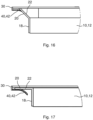
Figure 16 is a cross sectional detailed view of a next step of mounting the filter element to the installation frame; -
Figure 17 is a cross sectional detailed view of the filter element mounted to the installation frame; -
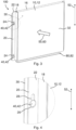
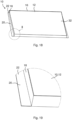
Figure 18 is a filter element for an ambient air filter device according to a further embodiment of the invention in an isometric view; -
Figure 19 is a detailed view of detail B according toFig. 18 ; -
Figure 20 is the filter element according toFig. 18 with a band segment prepared for mounted to the installation frame; -
Figure 21 is a detailed view of detail A according toFig. 20 ; -
Figure 22 is the filter element according toFigure 20 ready for mounting; -
Figure 23 is the installation frame of the further embodiment of the invention in an isometric view; -
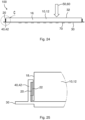
Figure 24 is a top view of the ambient air filter device according to the further embodiment with the filter element mounted; and -
Figure 25 is a detailed view of detail C according toFig. 24 . - In the drawings, like elements are referred to with equal reference numerals. The drawings are merely schematic representations, not intended to portray specific parameters of the invention. Moreover, the drawings are intended to depict only typical embodiments of the invention and therefore should not be considered as limiting the scope of the invention.
-
Figures 1 to 6 depict a first embodiment of the invention.Figure 1 depicts afilter element 10 for an ambientair filter device 100 for arrangement in a front area of a vehicle according to an embodiment of the invention in an isometric view.Figure 2 depicts aninstallation frame 30 for mounting thefilter element 10, whereas inFigure 3 the ambientair filter device 100 with the mounted filter element is shown.Figure 4 depicts a detailed view of detail A according toFigure 3 . - As shown in
Figure 1 , thefilter element 10 has afilter medium body 12 which is at least partially covered by asideband 18, wherein thesideband 18 has aband segment 22 folded down pointing away from thefilter medium body 12. Thefilter element 10 has anair inlet side 32 and anair outlet side 34. End faces of thefilter medium body 12 which are free from thesideband 18 may be covered with aheadband 16. - The ambient
air filter device 100 has aninstallation frame 30 which is designed for air to flow through it. - As shown in
Figure 2 , theinstallation frame 30 is provided with agrid 70 arranged parallel to thefilter element 10 through which a flow can pass and on which thefilter element 10 can be arranged. Thefilter element 10 is arranged on theinstallation frame 30, wherein theinstallation frame 30 provides aflow area 36 for thefilter element 10. Theinstallation frame 30 may be formed as part of the vehicle. - The
installation frame 30 has receivingelements 40 on opposing sides of theflow area 36 for mounting and/or dismounting thefilter element 10 along an insertion or removal direction 50 (seeFigure 3 ). The insertion or removal direction 50 is essentially parallel to a through-flow direction 60 through thefilter element 10. In particular the insertion or removal direction 50 may be parallel to a surface normal of thesupport surface 72 of theinstallation frame 30. Thesupport surface 72 in this embodiment is realized by thegrid 70 of theinstallation frame 30 and supports the mountedfilter element 10. - The receiving
elements 40 of theinstallation frame 30 comprise one ormore retaining members 42. Thefilter element 10 hascounter elements 20 arranged on theband segment 22 for cooperating with the retainingmembers 42. Thecounter elements 20 are each formed asoblong holes 24 in theband segment 22. - The
filter element 10, through which air flows from theair inlet side 32 to theair outlet side 34, may be arranged in theinstallation frame 30 by inserting thefilter element 10 with themating counter elements 20 into the retainingmembers 42 of the receivingelements 40 of theinstallation frame 30. - For forming the
band segments 22, thesideband 18 is L-shaped. Thecounter elements 20 extend in their longitudinal extension along a longitudinal extension of thefilter medium body 12. Thecounter elements 20 further may comprise at least regions which extend parallel to a planar extension of thefilter medium body 12. - In each case two
band segments 22, in particularparallel band segments 22, projecting from thefilter medium body 12 are arranged on the sides of thefilter medium body 12 facing away from one another. Theband segments 22 are arranged at a distance from one another, in particular in a through-flow direction 60 of thefilter element 10. - As shown in
Figure 2 , retainingmembers 42 of theinstallation frame 30 corresponding thereto may be in each case arranged on mutually opposite sides of thefilter medium body 12. - The retaining
members 42 are designed as projecting in the insertion or removal direction 50. The oblong holes 24 of thecounter elements 20 of thefilter element 10 haveopenings 26 in which the retainingmembers 42 engage during assembly of thefilter element 10. - As may especially be seen from
Figure 4 , In particular, the retainingmembers 42 may be mushroom-shaped. The oblong holes 24 have alarger opening 26 for insertion of the retainingmember 42 and aslot 28 connected to saidlarger opening 26 for fixing thefilter element 10 along a fixingdirection 52 in a final mounting position. Thus, thefilter element 10 may be mounted in the insertion or removal direction 50 to theinstallation frame 30. The retainingmembers 42 are fed through thelarger openings 26. Then thefilter element 10 may slide along the fixingdirection 52 in order to move the retainingmembers 42 to theslots 28 and fix thefilter element 10 to theinstallation frame 30. - The
installation frame 30 has an end stop 80, in particular a protrusion 82, at a lower end in the insertion or removal direction 50, for fixing thefilter element 10 in an intended mounting position. Thus the force acting on the retainingmembers 42 in the fixingdirection 52 may be reduced. - In
Figure 5 a plan view of the ambientair filter device 100 according toFigure 3 in a mounted state of thefilter element 10 is shown.Figure 6 depicts a side view of the ambientair filter device 100. - The
filter element 10 is shown in a state where the retainingmembers 42 are still in the center of thelarger opening 26 of theoblong hole 24. For moving thefilter element 10 in the final mounting position the retainingmembers 42 may be moved to theslots 28 of theoblong holes 24 in the fixingdirection 52. In this final mounting position thefilter element 10 is resting on the protrusion 82 of the end stop 80 of theinstallation frame 30. - In a use arrangement both the
air inlet side 32 and theair outlet side 34 of thefilter element 10 may be fluidically connected to the environment. - In
Figures 7 to 11 a further embodiment of the invention is shown. - In this embodiment the
filter element 10 is fixed to theinstallation frame 30 in the way of a ring binder. -
Figure 7 depicts afilter element 10 for an ambientair filter device 100 according to the further embodiment.Figure 8 depicts aninstallation frame 30, whereas inFigure 9 the ambientair filter device 100 with the mountedfilter element 10 is shown.Figure 10 depicts a detailed view of detail A according toFig. 9 . InFigure 11 mounting of thefilter element 10 to theinstallation frame 30 is depicted. - As can be seen from
Figure 7 , thecounter elements 20 in theband segments 22 of thefilter element 10 are also realized asoblong holes 24, but shaped in a rectangular way. - The retaining
members 42 of the receivingelements 40 arranged on both sides of theinstallation frame 30 are shaped as shorter stripes which may be bent at a right angle, as may especially be seen fromFigure 10 . - When mounting the
filter element 10 to theinstallation frame 30 the retainingmembers 42 may be fed through theoblong holes 24 of thecounter elements 20 thus fixing thefilter element 10 to theinstallation frame 30. - The mounting process is shown in
Figure 11 , where thefilter element 10 is hooked at one side to theinstallation frame 30, whereas the second side is still free. Next thefilter element 10 may be fixed on the second side by pressing on the first side in order to hook the oblong holes 24 on the second side to the retainingmembers 42. - In
Figures 12 to 17 a further embodiment of the invention is shown. - In this embodiment the
filter element 10 may be fixed to theinstallation frame 30 by retainingmembers 42 shaped as retaining clips. Here, the L-legs of thesideband 18 are pressed into the retaining clips and thefilter element 10 is thus secured against falling out. Theband segment 22 is therefore slid under the retaining clips. -
Figure 12 depicts afilter element 10 for an ambientair filter device 100 according to the further embodiment.Figure 13 depicts aninstallation frame 30, whereas inFigure 14 the ambientair filter device 100 with the mountedfilter element 10 is shown.Figure 15 depicts a cross sectional detailed view of a first step of mounting thefilter element 10 to theinstallation frame 30,Figure 16 a next step of mounting andFigure 17 the filter element mounted to the installation frame. - The different steps of fixing the
filter element 10 to theinstallation frame 30 may be seen fromFigures 15 to 17 . - In
Figure 15 thefilter element 10 is moved towards theinstallation frame 30. Theband segment 22 is still in a nearly straight way. Thesideband 18 is not yet L-shaped. As thefilter element 10 is further moved towards theinstallation frame 30 theband segment 22 is bent further in order to slip under the retaining clip of the retainingmember 42, as may be seen fromFigure 16 . In the final position inFigure 17 thesideband 18 is completely L-shaped and theband segment 22 is fully flat pressed towards theinstallation frame 30 by the retaining clip thus fixing thefilter element 10. - In
Figures 18 to 25 a further embodiment of the invention is shown. - In this embodiment the
filter element 10 is fixed to theinstallation frame 30 by foldedsidebands 18. -
Figure 18 depicts afilter element 10 for an ambient air filter device according to the further embodiment, whereasFigure 19 shows a detailed view of detail B according toFig. 18 .Figure 20 depicts thefilter element 10 with aband segment 22 prepared for being mounted to theinstallation frame 30, whereasFigure 21 shows a detailed view of detail A according toFig. 20 . InFigure 22 thefilter element 10 is depicted ready for mounting and inFigure 23 thecorresponding installation frame 30. - As may be seen from
Figure 18 , thesideband 18 is in the L-shape and theband segment 22 of thefilter element 10 first is conically cut. - Next, as shown in
Figures 20 and 21 , theband segment 22 is folded up parallel to the side of thefilter medium body 12. InFigure 22 thefilter element 10 is ready for being mounted to theinstallation frame 30 show inFigure 23 . Theinstallation frame 30 for this purpose has retainingmembers 42 as receivingelements 40 which correspond to the foldedband segments 22 such that thefilter element 10 may be slid with theband segments 22 into the retainingmembers 42. -
Figure 24 shows a top view of the ambientair filter device 100 with thefilter element 10 mounted, whereasFigure 25 shows a detailed view of detail C according toFig. 24 . Thefilter element 10 there is slid into the receivingelements 40 of theinstallation frame 30 in a direction parallel to theflow area 36. Especially in the detailed view it may be seen how the foldedband segment 22 is slid under the retainingmember 42 of theinstallation frame 30 which is bent on an upper side in order to fix theband segment 22. Thus theband segment 22 is hold by the retainingmember 42 shaped as a groove. -
- 10
- filter element
- 12
- filter medium body
- 14
- filter medium
- 16
- head band
- 18
- side band
- 20
- counter element
- 22
- band segment
- 24
- oblong hole
- 26
- opening
- 28
- slot
- 30
- installation frame
- 32
- air inlet side
- 34
- air outlet side
- 36
- flow area
- 40
- receiving element
- 42
- retaining member
- 50
- insertion or removal direction
- 52
- fixing direction
- 60
- through-flow direction
- 70
- grid
- 72
- support surface
- 80
- end stop
- 82
- protrusion
- 100
- ambient air filter device
Claims (11)
- An ambient air filter device (100) for arrangement in a front area of a vehicle, the ambient air filter device (100) comprising:an installation frame (30) for air to flow through the installation frame (30); anda filter element (10) arranged on the installation frame (30), the installation frame (30) providing a flow area (36) for the filter element (10), and the filter element (10) comprising an air inlet side (32) and an air outlet side (34),wherein the installation frame (30) comprises receiving elements (40) on opposing sides of the flow area (36) of the installation frame (30), the receiving elements (40) being for mounting and/or dismounting the filter element (10) along an insertion or removal direction (50),wherein the filter element (10) comprises a filter medium body (12) that is at least partially covered by a sideband (18) comprising a band segment (22) folded down and pointing away from the filter medium body (12),wherein the receiving elements (40) of the installation frame (30) comprise retaining members (42), andwherein the filter element (10) comprises counter elements (20) arranged on the band segment (22) and for cooperating with the retaining members (42).
- The ambient air filter device according to claim 1, wherein the insertion or removal direction (50) is essentially parallel to a through-flow direction (60) through the filter element (10).
- The ambient air filter device according to claim 1 or 2, wherein the counter elements (20) are each formed as oblong holes (24) through the band segment (22).
- The ambient air filter device according to any one of the preceding claims, wherein the counter elements (20) comprise at least regions extending parallel to a planar extension of the filter medium body (12).
- The ambient air filter device according to claim 3 or 4, wherein the retaining members (42) project in the insertion or removal direction (50), in particular the retaining members (42) being mushroom-shaped, and
wherein the oblong holes (24) comprise openings (26) in which the retaining members (42) are inserted during assembly of the filter element (10), and comprise slots (28) being connected to the openings (26) and for fixing the filter element (10) along a fixing direction (52) in a final mounting position. - The ambient air filter device according to any one of the preceding claims, wherein the installation frame (30) comprises an end stop (80), in particular a protrusion (82), at a lower end in the insertion or removal direction (50), the end stop (80) being for fixing the filter element (10) in an intended mounting position.
- The ambient air filter device according to any one of the preceding claims, wherein end faces of the filter medium body (12) that are free from the sideband (18) are covered with a headband (16).
- The ambient air filter device according to any one of the preceding claims, wherein in a use arrangement, both the air inlet side (32) and the air outlet side (34) of the filter medium body (12) are fluidically connected to the environment.
- The ambient air filter device according to any one of the preceding claims, wherein the installation frame (30) comprises a grid (70) arranged parallel to the filter element (10) through which the air flows and on which the filter element (10) is arranged.
- The ambient air filter device according to any one of the preceding claims, wherein the installation frame (30) is formed as part of the vehicle.
- A use of the filter element (10) in the ambient air filter device (100) according to any one of the preceding claims,
wherein the filter element (10), through which the air flows from the air inlet side (32) to the air outlet side (34), is arranged in the installation frame (30) by inserting the filter element (10) with the counter elements (20) into the retaining members (42) of the receiving elements (40) of the installation frame (30).
Priority Applications (1)
| Application Number | Priority Date | Filing Date | Title |
|---|---|---|---|
| EP23161655.8A EP4431171A1 (en) | 2023-03-14 | 2023-03-14 | Ambient air filter device and use of a filter element in an ambient air filter device |
Applications Claiming Priority (1)
| Application Number | Priority Date | Filing Date | Title |
|---|---|---|---|
| EP23161655.8A EP4431171A1 (en) | 2023-03-14 | 2023-03-14 | Ambient air filter device and use of a filter element in an ambient air filter device |
Publications (1)
| Publication Number | Publication Date |
|---|---|
| EP4431171A1 true EP4431171A1 (en) | 2024-09-18 |
Family
ID=85640835
Family Applications (1)
| Application Number | Title | Priority Date | Filing Date |
|---|---|---|---|
| EP23161655.8A Withdrawn EP4431171A1 (en) | 2023-03-14 | 2023-03-14 | Ambient air filter device and use of a filter element in an ambient air filter device |
Country Status (1)
| Country | Link |
|---|---|
| EP (1) | EP4431171A1 (en) |
Citations (5)
| Publication number | Priority date | Publication date | Assignee | Title |
|---|---|---|---|---|
| US6723150B2 (en) * | 2002-02-28 | 2004-04-20 | American Standard International Inc. | Air filter with expandable filter media |
| DE102007015662A1 (en) * | 2007-03-31 | 2008-10-02 | Carl Freudenberg Kg | A filter assembly |
| US20130125520A1 (en) * | 2011-11-22 | 2013-05-23 | Joseph J. Gorman | Holding frame |
| US8747507B2 (en) * | 2011-06-21 | 2014-06-10 | Carl Freudenberg Kg | Filter element with guide shaft |
| DE102020123461A1 (en) * | 2020-09-09 | 2022-03-10 | Mann+Hummel Gmbh | Filter element, cabin air filter and manufacturing process |
-
2023
- 2023-03-14 EP EP23161655.8A patent/EP4431171A1/en not_active Withdrawn
Patent Citations (6)
| Publication number | Priority date | Publication date | Assignee | Title |
|---|---|---|---|---|
| US6723150B2 (en) * | 2002-02-28 | 2004-04-20 | American Standard International Inc. | Air filter with expandable filter media |
| DE102007015662A1 (en) * | 2007-03-31 | 2008-10-02 | Carl Freudenberg Kg | A filter assembly |
| US8747507B2 (en) * | 2011-06-21 | 2014-06-10 | Carl Freudenberg Kg | Filter element with guide shaft |
| US20130125520A1 (en) * | 2011-11-22 | 2013-05-23 | Joseph J. Gorman | Holding frame |
| DE102020123461A1 (en) * | 2020-09-09 | 2022-03-10 | Mann+Hummel Gmbh | Filter element, cabin air filter and manufacturing process |
| WO2022053276A1 (en) | 2020-09-09 | 2022-03-17 | Mann+Hummel Gmbh | Filter element, interior air filter and production method |
Similar Documents
| Publication | Publication Date | Title |
|---|---|---|
| US10954899B2 (en) | Filter and filter cartridge | |
| CN108602005B (en) | Filter element, element frame of a filter element, filter bellows of a filter element, filter housing and filter | |
| EP3442678B1 (en) | Filter system | |
| EP2618911B1 (en) | Filter assembly comprising a pre-filter device and a pre-filter mounting plate therefor | |
| EP2568140A1 (en) | Exhaust gas aftertreatment device | |
| CN210858906U (en) | Mounting assembly for an aftertreatment system | |
| US20090126324A1 (en) | Authorized Filter Servicing and Replacement | |
| EP3067232A1 (en) | Cooling duct apparatus for onboard battery | |
| US8460420B2 (en) | Filter element | |
| US20080099641A1 (en) | Fastenerless attachment system applied to vehicle engine cooling module components | |
| WO2013165463A2 (en) | Holding frame assembly and flexible retainers for same | |
| CN103770630B (en) | The installed part of automotive field vehicle body attachment and the mounting assembly with this installed part | |
| US20150013291A1 (en) | Filter Element with Retaining Surfaces, Filter with a Filter Element and Filter Housing of a Filter | |
| CN108602004B (en) | Filter housing and filter | |
| CN108472568A (en) | Including the filter cell for tilting end plate and corresponding filter housings | |
| WO2013078296A1 (en) | Holding frame | |
| US20170319997A1 (en) | Filter element | |
| CN110243204B (en) | Heat exchanger assembly and method of installing a heat exchanger | |
| JP2011216547A (en) | Electronic equipment structure | |
| CN216011152U (en) | Machine and air conditioner in filter assembly, air conditioning | |
| CN106052060B (en) | Machine in grid subassembly and air conditioning of machine in air conditioning | |
| CN204507018U (en) | A kind of anti-drop structure of assembly unit | |
| EP4570351A1 (en) | Ambient air filter device and filter element in ambient air filter device | |
| CN210292098U (en) | An air purification module installation structure and air conditioner | |
| WO2024017691A1 (en) | Ambient air filter device, use of a filter element, and motor vehicle |
Legal Events
| Date | Code | Title | Description |
|---|---|---|---|
| PUAI | Public reference made under article 153(3) epc to a published international application that has entered the european phase |
Free format text: ORIGINAL CODE: 0009012 |
|
| STAA | Information on the status of an ep patent application or granted ep patent |
Free format text: STATUS: THE APPLICATION HAS BEEN PUBLISHED |
|
| AK | Designated contracting states |
Kind code of ref document: A1 Designated state(s): AL AT BE BG CH CY CZ DE DK EE ES FI FR GB GR HR HU IE IS IT LI LT LU LV MC ME MK MT NL NO PL PT RO RS SE SI SK SM TR |
|
| STAA | Information on the status of an ep patent application or granted ep patent |
Free format text: STATUS: THE APPLICATION IS DEEMED TO BE WITHDRAWN |
|
| 18D | Application deemed to be withdrawn |
Effective date: 20250319 |