EP4431138A1 - Atomizer and atomizing device - Google Patents
Atomizer and atomizing device Download PDFInfo
- Publication number
- EP4431138A1 EP4431138A1 EP23168832.6A EP23168832A EP4431138A1 EP 4431138 A1 EP4431138 A1 EP 4431138A1 EP 23168832 A EP23168832 A EP 23168832A EP 4431138 A1 EP4431138 A1 EP 4431138A1
- Authority
- EP
- European Patent Office
- Prior art keywords
- atomizing
- interface
- atomizer
- liquid storage
- flow channel
- Prior art date
- Legal status (The legal status is an assumption and is not a legal conclusion. Google has not performed a legal analysis and makes no representation as to the accuracy of the status listed.)
- Granted
Links
Images




Classifications
-
- A—HUMAN NECESSITIES
- A61—MEDICAL OR VETERINARY SCIENCE; HYGIENE
- A61M—DEVICES FOR INTRODUCING MEDIA INTO, OR ONTO, THE BODY; DEVICES FOR TRANSDUCING BODY MEDIA OR FOR TAKING MEDIA FROM THE BODY; DEVICES FOR PRODUCING OR ENDING SLEEP OR STUPOR
- A61M11/00—Sprayers or atomisers specially adapted for therapeutic purposes
- A61M11/005—Sprayers or atomisers specially adapted for therapeutic purposes using ultrasonics
-
- A—HUMAN NECESSITIES
- A61—MEDICAL OR VETERINARY SCIENCE; HYGIENE
- A61M—DEVICES FOR INTRODUCING MEDIA INTO, OR ONTO, THE BODY; DEVICES FOR TRANSDUCING BODY MEDIA OR FOR TAKING MEDIA FROM THE BODY; DEVICES FOR PRODUCING OR ENDING SLEEP OR STUPOR
- A61M11/00—Sprayers or atomisers specially adapted for therapeutic purposes
- A61M11/04—Sprayers or atomisers specially adapted for therapeutic purposes operated by the vapour pressure of the liquid to be sprayed or atomised
-
- B—PERFORMING OPERATIONS; TRANSPORTING
- B05—SPRAYING OR ATOMISING IN GENERAL; APPLYING FLUENT MATERIALS TO SURFACES, IN GENERAL
- B05B—SPRAYING APPARATUS; ATOMISING APPARATUS; NOZZLES
- B05B12/00—Arrangements for controlling delivery; Arrangements for controlling the spray area
- B05B12/08—Arrangements for controlling delivery; Arrangements for controlling the spray area responsive to condition of liquid or other fluent material to be discharged, of ambient medium or of target ; responsive to condition of spray devices or of supply means, e.g. pipes, pumps or their drive means
- B05B12/085—Arrangements for controlling delivery; Arrangements for controlling the spray area responsive to condition of liquid or other fluent material to be discharged, of ambient medium or of target ; responsive to condition of spray devices or of supply means, e.g. pipes, pumps or their drive means responsive to flow or pressure of liquid or other fluent material to be discharged
-
- B—PERFORMING OPERATIONS; TRANSPORTING
- B05—SPRAYING OR ATOMISING IN GENERAL; APPLYING FLUENT MATERIALS TO SURFACES, IN GENERAL
- B05B—SPRAYING APPARATUS; ATOMISING APPARATUS; NOZZLES
- B05B17/00—Apparatus for spraying or atomising liquids or other fluent materials, not covered by the preceding groups
- B05B17/04—Apparatus for spraying or atomising liquids or other fluent materials, not covered by the preceding groups operating with special methods
- B05B17/06—Apparatus for spraying or atomising liquids or other fluent materials, not covered by the preceding groups operating with special methods using ultrasonic or other kinds of vibrations
- B05B17/0607—Apparatus for spraying or atomising liquids or other fluent materials, not covered by the preceding groups operating with special methods using ultrasonic or other kinds of vibrations generated by electrical means, e.g. piezoelectric transducers
- B05B17/0638—Apparatus for spraying or atomising liquids or other fluent materials, not covered by the preceding groups operating with special methods using ultrasonic or other kinds of vibrations generated by electrical means, e.g. piezoelectric transducers spray being produced by discharging the liquid or other fluent material through a plate comprising a plurality of orifices
- B05B17/0646—Vibrating plates, i.e. plates being directly subjected to the vibrations, e.g. having a piezoelectric transducer attached thereto
-
- A—HUMAN NECESSITIES
- A61—MEDICAL OR VETERINARY SCIENCE; HYGIENE
- A61M—DEVICES FOR INTRODUCING MEDIA INTO, OR ONTO, THE BODY; DEVICES FOR TRANSDUCING BODY MEDIA OR FOR TAKING MEDIA FROM THE BODY; DEVICES FOR PRODUCING OR ENDING SLEEP OR STUPOR
- A61M15/00—Inhalators
- A61M15/0085—Inhalators using ultrasonics
-
- A—HUMAN NECESSITIES
- A61—MEDICAL OR VETERINARY SCIENCE; HYGIENE
- A61M—DEVICES FOR INTRODUCING MEDIA INTO, OR ONTO, THE BODY; DEVICES FOR TRANSDUCING BODY MEDIA OR FOR TAKING MEDIA FROM THE BODY; DEVICES FOR PRODUCING OR ENDING SLEEP OR STUPOR
- A61M16/00—Devices for influencing the respiratory system of patients by gas treatment, e.g. ventilators; Tracheal tubes
- A61M16/08—Bellows; Connecting tubes ; Water traps; Patient circuits
- A61M16/0816—Joints or connectors
- A61M16/0833—T- or Y-type connectors, e.g. Y-piece
-
- A—HUMAN NECESSITIES
- A61—MEDICAL OR VETERINARY SCIENCE; HYGIENE
- A61M—DEVICES FOR INTRODUCING MEDIA INTO, OR ONTO, THE BODY; DEVICES FOR TRANSDUCING BODY MEDIA OR FOR TAKING MEDIA FROM THE BODY; DEVICES FOR PRODUCING OR ENDING SLEEP OR STUPOR
- A61M16/00—Devices for influencing the respiratory system of patients by gas treatment, e.g. ventilators; Tracheal tubes
- A61M16/0003—Accessories therefor, e.g. sensors, vibrators, negative pressure
- A61M2016/0015—Accessories therefor, e.g. sensors, vibrators, negative pressure inhalation detectors
- A61M2016/0018—Accessories therefor, e.g. sensors, vibrators, negative pressure inhalation detectors electrical
- A61M2016/0021—Accessories therefor, e.g. sensors, vibrators, negative pressure inhalation detectors electrical with a proportional output signal, e.g. from a thermistor
-
- A—HUMAN NECESSITIES
- A61—MEDICAL OR VETERINARY SCIENCE; HYGIENE
- A61M—DEVICES FOR INTRODUCING MEDIA INTO, OR ONTO, THE BODY; DEVICES FOR TRANSDUCING BODY MEDIA OR FOR TAKING MEDIA FROM THE BODY; DEVICES FOR PRODUCING OR ENDING SLEEP OR STUPOR
- A61M16/00—Devices for influencing the respiratory system of patients by gas treatment, e.g. ventilators; Tracheal tubes
- A61M16/0003—Accessories therefor, e.g. sensors, vibrators, negative pressure
- A61M2016/003—Accessories therefor, e.g. sensors, vibrators, negative pressure with a flowmeter
- A61M2016/0033—Accessories therefor, e.g. sensors, vibrators, negative pressure with a flowmeter electrical
-
- A—HUMAN NECESSITIES
- A61—MEDICAL OR VETERINARY SCIENCE; HYGIENE
- A61M—DEVICES FOR INTRODUCING MEDIA INTO, OR ONTO, THE BODY; DEVICES FOR TRANSDUCING BODY MEDIA OR FOR TAKING MEDIA FROM THE BODY; DEVICES FOR PRODUCING OR ENDING SLEEP OR STUPOR
- A61M2202/00—Special media to be introduced, removed or treated
- A61M2202/04—Liquids
- A61M2202/0468—Liquids non-physiological
-
- A—HUMAN NECESSITIES
- A61—MEDICAL OR VETERINARY SCIENCE; HYGIENE
- A61M—DEVICES FOR INTRODUCING MEDIA INTO, OR ONTO, THE BODY; DEVICES FOR TRANSDUCING BODY MEDIA OR FOR TAKING MEDIA FROM THE BODY; DEVICES FOR PRODUCING OR ENDING SLEEP OR STUPOR
- A61M2205/00—General characteristics of the apparatus
- A61M2205/58—Means for facilitating use, e.g. by people with impaired vision
- A61M2205/583—Means for facilitating use, e.g. by people with impaired vision by visual feedback
-
- B—PERFORMING OPERATIONS; TRANSPORTING
- B05—SPRAYING OR ATOMISING IN GENERAL; APPLYING FLUENT MATERIALS TO SURFACES, IN GENERAL
- B05B—SPRAYING APPARATUS; ATOMISING APPARATUS; NOZZLES
- B05B7/00—Spraying apparatus for discharge of liquids or other fluent materials from two or more sources, e.g. of liquid and air, of powder and gas
- B05B7/0012—Apparatus for achieving spraying before discharge from the apparatus
Definitions
- the disclosure relates to the technical field of atomization, and particularly to an atomizer and an atomizing device.
- a corner may be formed inside the atomizing cup.
- bubbles generated during atomization of the atomizing sheet may float to the corner, and when the formed bubbles are large, the bubbles may separate the atomizing sheet from the atomizing liquid, resulting in atomization interruption.
- the atomizer according to the embodiment of the disclosure at least has the following beneficial effects.
- the part of the liquid storage cavity is higher than the corner.
- the bubbles may break away from the corner and float into the liquid storage cavity.
- the length L of the corner is less than or equal to 3 mm, and the diameter of the flow channel is greater than or equal to 7 mm, when the flow channel has not been completely covered by the bubbles, the bubbles will float into the liquid storage cavity, so as to avoid the bubbles from blocking the flow channel, thus preventing the bubbles from separating the atomizing sheet from the atomizing liquid, and preventing atomization interruption.
- the cup body further comprises a connecting portion, one side of the connecting portion is connected to the liquid storage portion, and the other side of the connecting portion is connected to the cup mouth, so as to define the atomizing cavity with the cup mouth;
- the atomizer further comprises the waterproof member, the waterproof member has an elastic structure, the waterproof member is provided with a mounting hole, a hole wall of the mounting hole is provided with a clamping groove, and an outer edge of the atomizing assembly is clamped into the clamping groove.
- the atomizing assembly further comprises an adapter sheet, the adapter sheet is provided with a through hole, the through hole is communicated with the flow channel, the atomizing sheet is located on one side of the adapter sheet away from the power supply interface and electrically connected with the adapter sheet, and the adapter sheet is configured for being electrically connected with the external electrical connector.
- the adapter sheet is configured for abutting against the external connector, and the atomizing sheet is detachably connected with the adapter sheet.
- a distance between a center of the through hole and the corner is greater than a radius of the flow channel.
- the cup mouth is further provided with a groove, the groove is provided with an opening, the cup body is connected to the opening, so as to define the liquid storage cavity, and the atomizing assembly is clamped between the cup mouth and the cup body.
- the atomizing cup further comprises an expansion interface, the expansion interface is connected to the cup body, the expansion interface is provided with a liquid filling hole, the liquid filling hole is communicated with the liquid storage cavity, and the expansion interface is configured for being connected with an external liquid storage container.
- An atomizing device according to an embodiment in a second aspect of the disclosure comprises the atomizer according to the embodiment in the first aspect.
- the atomizing device according to the embodiment of the disclosure at least has the following beneficial effects.
- the atomizer according to the embodiment in the first aspect is used, and in the atomizer according to the embodiment in the first aspect, because a part of the liquid storage cavity is located on one side of the corner away from the power supply interface in the embodiment, when the flow channel is in a horizontal position and the corner is located above the atomizing sheet, the part of the liquid storage cavity is higher than the corner.
- the bubbles float to the corner, as the bubbles grow to a certain extent, the bubbles may break away from the corner and float into the liquid storage cavity.
- the length L of the corner is less than or equal to 3 mm, and the diameter of the flow channel is greater than or equal to 7 mm, when the flow channel has not been completely covered by the bubbles, the bubbles will float into the liquid storage cavity, so as to avoid the bubbles from blocking the flow channel, thus preventing the bubbles from separating the atomizing sheet from the atomizing liquid, and preventing atomization interruption.
- the atomizing device further comprises a host, a data line and a three-way pipe;
- the atomizing device further comprises a gas channel assembly
- the data line comprises two output ends, one of the output ends is connected to the atomizer and the other of the output ends is connected to the gas channel assembly
- the gas channel assembly comprises a pipe body and a flow sensor
- the flow sensor is arranged in the pipe body and configured for detecting a gas flow
- one end of the pipe body is communicated with the third interface and the other end of the pipe body is configured for allowing gas to enter the pipe body.
- an included angle between an axis of the first interface and an axis of the second interface is ⁇ , and 90° ⁇ 180°.
- the meaning of several refers to be one or more, and the meaning of "a plurality of' refers to be two or more.
- the meanings of greater than, less than, more than, and the like are understood as not including the following number, while the meanings of above, below, within, and the like are understood as including the following number. If there is the description of first and second, it is only for the purpose of distinguishing between technical features, and should not be understood as indicating or implying relative importance, implicitly indicating the number of the indicated technical features or implicitly indicating the order of the indicated technical features.
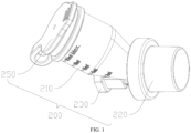
- FIG. 1 is a schematic structural diagram of an atomizer according to an embodiment of the disclosure
- FIG. 2 is a sectional view of FIG. 1
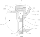
- FIG. 3 is an enlarged diagram of a region A in FIG. 2
- FIG. 4 is a schematic diagram marking dimension parameters of a flow channel and a through hole.
- an atomizer 1000 according to an embodiment in a first aspect comprises an atomizing assembly 100 and an atomizing cup 200.
- the atomizing assembly 100 comprises an atomizing sheet 110 for atomizing an atomizing liquid.
- the atomizing cup 200 comprises a cup body 210, a cup mouth 220 and a power supply interface 230.
- the power supply interface 230 is configured for being connected with an external electrical connector, the cup body 210 and the power supply interface 230 are located on the same side of the cup mouth 220.
- the cup body 210 comprises a liquid storage portion 211, the liquid storage portion 211 is provided with a liquid storage cavity 2111, and the liquid storage cavity 2111 is configured for storing the atomizing liquid.
- the cup body 210 may be made of a transparent material, or partially made of a transparent material, so that a user can visually observe the atomizing liquid in the liquid storage cavity 2111, and the user can replace the atomizing liquid in time, thus preventing the atomizing sheet 110 from dry burning.
- the atomizing cup 200 is further provided with an atomizing cavity 240, the atomizing assembly 100 is arranged in the atomizing cavity 240, the cup mouth 220 is provided with a gas outlet 221, and the gas outlet 221 is communicated with the atomizing cavity 240 and configured for discharging mist generated in the atomizing cavity 240.
- a flow channel portion 300 is further arranged between the atomizing assembly 100 and the liquid storage portion 211, the flow channel portion 300 is provided with a flow channel 310, the flow channel 310 communicates the atomizing cavity 240 with the liquid storage cavity 2111, the liquid storage portion 211 and the power supply interface 230 are distributed along a radial direction of the flow channel 310, and the liquid storage portion 211 is obliquely arranged away from the power supply interface 230, so as to avoid the power supply interface 230.
- an included angle between the cup body 210 and the cup mouth may 135°, 150°, and the like, which is set according to sizes of the cup body 210 and the power supply interface 230, so as to form a mounting space for the power supply interface 230.
- a corner 320 is formed on a side wall of the flow channel 310 away from the power supply interface 230, a length of the corner 320 is L, L ⁇ 3 mm, a diameter of the flow channel is D, D ⁇ 7mm, and a part of the liquid storage cavity 2111 is located on one side of the corner 320 away from the power supply interface 230.
- a part of the liquid storage cavity 2111 is located on one side of the corner 320 away from the power supply interface 230. Therefore, during use, when the flow channel 310 is in a horizontal position, and the corner 320 is located above the atomizing sheet 110, the part of the liquid storage cavity 2111 is higher than the corner 320. When bubbles float to the corner 320, as the bubbles grow to a certain extent, the bubbles may break away from the corner 320 and float into the liquid storage cavity 2111 from the flow channel 310.
- the bubbles may float into the liquid storage cavity 2111 when the bubbles grow to an extent of not completely covering the flow channel 310, so as to avoid the bubbles from blocking the flow channel 310, thus preventing the bubbles from separating the atomizing sheet 110 from the atomizing liquid and preventing atomization interruption.
- the atomizer 1000 will be interrupted.
- the bubbles may not separate the atomizing sheet 110 from the atomizing liquid, so that the atomizer 1000 will not be interrupted during working.
- FIG. 5 is a sectional view of an atomizer according to another embodiment of the disclosure.
- FIG. 6 is an enlarged diagram of a region B in FIG. 5 .
- the cup body 210 further comprises a connecting portion 212, one side of the connecting portion 212 is connected to the liquid storage portion 211, and the other side of the connecting portion 212 is connected to the cup mouth, so as to define the atomizing cavity 240 with the cup mouth 220.
- the atomizing assembly 100 abuts against one side of the connecting portion 212 away from the liquid storage portion 211, and the connecting portion 212 is configured to form the flow channel portion 300 (as shown in FIG. 6 ).
- the atomizer 1000 further comprises a waterproof member 400, and the waterproof member 400 may be a prefabricated part or a waterproof glue.
- the waterproof member 400 is arranged in the atomizing cavity 240, at least a part of the waterproof member 400 is clamped between the connecting portion 212 and the atomizing assembly 100, and the waterproof member 400 and the connecting portion 212 are configured to jointly form the flow channel portion 300 (as shown in FIG. 6 ).
- the waterproof member 400 is configured for improving a sealing performance between the connecting portion 212 and the atomizing assembly 100, thus preventing a gap from being formed between the atomizing assembly 100 and a cavity wall of the atomizing cavity 240 to make the atomizing liquid not subjected to atomization flow into the atomizing cavity 240.
- the atomizing liquid can be prevented from leaking when the atomizer 1000 is not in use.
- the atomizing liquid not subjected to atomization is prevented from being directly inhaled into human body when the atomizer is in use.
- the waterproof member 400 has an elastic structure
- the waterproof member 400 is provided with a mounting hole
- a hole wall of the mounting hole is provided with a clamping groove
- the atomizing assembly 100 is arranged in the mounting hole, and an outer edge of the atomizing assembly 100 is clamped into the clamping groove.
- the clamping groove is recessed along a radial direction of the mounting hole, and extends along a circumferential direction of the mounting hole, so as to form a closed annular groove.
- the atomizing assembly 100 is inserted into the mounting hole first, so that the waterproof member 400 is pressed and deformed.
- the waterproof member 400 When the edge of the atomizing assembly 100 enters the clamping groove, the waterproof member 400 is restored under an elastic effect. At the moment, an inner wall of the waterproof member 400 abuts against the outer edge of the atomizing assembly 100, and an outer wall of the waterproof member 400 is attached to the inner wall of the atomizing cavity 240, thus improving a sealing performance between the atomizing assembly 100 and the atomizing cup 200.
- the atomizing assembly 100 further comprises an adapter sheet 120, the adapter sheet 120 is configured for being electrically connected with an external electrical connector, and the adapter sheet 120 is electrically connected with the atomizing sheet 110.
- the adapter sheet 120 is provided with a through hole 121, and the atomizing sheet 110 is connected to one side of the adapter sheet 120 away from the interface and electrically connected with the adapter sheet 120, so as to supply power to the atomizing sheet 110.
- the through hole 121 is communicated with the flow channel 310 and configured for exposing the atomizing sheet 110, so that the atomizing sheet 110 is contacted with the atomizing liquid in the flow channel 310.
- the atomizing sheet 110 is electrically connected with the adapter sheet 120. Therefore, during manufacturing, it is only necessary to design the adapter sheet 120 in a corresponding shape to adapt to the existing atomizing sheet 110 in the market, without needing to design a structure of the atomizer 1000 according to a specification of the existing atomizing sheet 110, thus improving the design flexibility of the atomizer 1000 and simplifying the design difficulty.
- the adapter sheet 120 is configured for abutting against the external electrical connector, and the adapter sheet 120 is detachably connected with the atomizing sheet 110.
- the external connector is a pogo pin. After the pogo pin is connected with the power supply interface 230, it extends into the atomizing cavity 240 and abuts against the adapter sheet 120, so as to supply power to the adapter sheet 120. It can be understood that, after using for many times, wear may occur between the pogo pin and the adapter sheet 120, so that replacement is required. Because the adapter sheet 120 and the atomizing sheet 110 are detachably connected in the embodiment of the disclosure, it is only necessary to disassemble the adapter sheet 120 during replacement, thus saving the maintenance cost.
- a distance H between a center of the through hole 121 and the corner 320 is greater than a radius R of the flow channel 310. That is, when the flow channel 310 is horizontally arranged and the corner 320 is located above the atomizing sheet 110, a center of the atomizing sheet 110 is located below a center of the flow channel 310, which means that the atomizing sheet 110 is located at a relatively low position of the flow channel 310, thus reducing the residual atomizing liquid. As shown in FIG.
- the lowest edge of the atomizing sheet 110 is flush with the lowest edge of the flow channel 310, so that the atomizing liquid flowing into the flow channel 310 can all be contacted with the atomizing sheet 110. Therefore, the atomizing liquid in the flow channel 310 can be atomized by being contacted with the atomizing sheet 110, thus reducing waste of the atomizing liquid and saving a use cost of the user.
- the atomizing liquid is a drug
- eccentric arrangement of the atomizing sheet 110 and the flow channel 310 can reduce the residual atomizing liquid, so as to ensure a therapeutic effect.
- one end of the cup mouth 220 facing the cup body is provided with a groove, the groove is provided with an opening, the cup body 210 is inserted into the cup mouth 220 and covers the opening of the cup mouth, so as to form the atomizing cavity 240, and the atomizing assembly 100 is clamped between the cup mouth 220 and the cup body 210. Therefore, the atomizing sheet 110 is simpler to fix, and the atomizing assembly 100 is fixed without other connectors, thus simplifying an assembly process and improving assembly efficiency.
- the waterproof member 400 is arranged at the opening, the mounting hole of the waterproof member 400 and the groove define the atomizing cavity 240, and the waterproof member 400 is clamped between the cup mouth 220 and the cup body 210, as shown in FIG. 2 .
- FIG. 7 is a schematic structural diagram of an atomizer according to another embodiment of the disclosure.
- the atomizing cup 200 further comprises an expansion interface 260, the expansion interface 260 is connected to the cup body 210, the expansion interface 260 is provided with a liquid filling hole, and the liquid filling hole is communicated with the liquid storage cavity 2111 and configured for adding the atomizing liquid to the liquid storage cavity 2111.
- the expansion interface 260 is configured for being connected with an external liquid storage container. On one hand, it facilitates connection of the external liquid storage container with the atomizing cup 200 when adding the atomizing liquid.
- an outer wall of the expansion interface 260 is provided with a thread, so that the external liquid storage container is connected with the atomizer 1000 in the embodiment of the disclosure through the thread.
- the expansion interface 260 may be further provided with a magnetic suction member, a fastener, and the like, so that the external liquid storage container can be quickly connected with the atomizer 1000 in the embodiment of the disclosure.
- the atomizer 1000 further comprises a cup cover 250, the cup cover 250 is detachably connected to the liquid filling hole, so as to selectively open or close the liquid filling hole, such as opening the cup cover 250 when adding the atomizing liquid, and blocking the liquid filling hole by the cup cover 250 after adding the atomizing liquid, thus preventing the drug liquid from being polluted and leaking.
- FIG. 8 is a schematic structural diagram of an atomizing device according to another embodiment of the disclosure.
- An atomizing device according to an embodiment in a second aspect comprises the atomizer 1000 according to the embodiment in the first aspect. Because the atomizer 1000 according to the embodiment in the first aspect is used in the embodiment, and in the atomizer 1000 according to the embodiment in the first aspect, a part of the liquid storage cavity 2111 is located on one side of the corner 320 away from the power supply interface 230, when the flow channel 310 is in a horizontal position and the corner 320 is located above the atomizing sheet 110, the part of the liquid storage cavity is higher than the corner 320.
- the bubbles may break away from the corner 320 and float into the liquid storage cavity 2111.
- the length L of the corner 320 is less than or equal to 3 mm, and the diameter of the flow channel 310 is greater than or equal to 7 mm, when the flow channel 310 has not been completely covered by the bubbles, the bubbles will float into the liquid storage cavity 2111, so as to avoid the bubbles from blocking the flow channel 310, thus preventing the bubbles from separating the atomizing sheet 110 from the atomizing liquid, and preventing atomization interruption.
- FIG. 9 is a schematic structural diagram of a three-way pipe in FIG. 8 .
- the atomizing device further comprises a host 500, a data line 600 and a three-way pipe 700.
- the data line 600 comprises an input end 610 and at least one output end 620, the input end 610 is connected to the host 500, and the at least one output end 620 is connected to the atomizer 1000.
- the host 500 is configured for supplying power to the atomizer 1000, and may also be configured for controlling an atomizing function of the atomizer 1000, for example, controlling start or stop of the atomizer 1000, the atomizing speed, etc.
- the three-way pipe 700 comprises a first interface 710, a second interface 720 and a third interface 730.
- the atomizer 1000 is connected to the first interface 710, and the second interface 720 is configured for discharging mist for a user to use.
- the third interface 730 is configured for allowing gas to enter the three-way pipe 700.
- the third interface 730 is directly communicated with an external space.
- air can enter the three-way pipe 700 through the third interface 730, and the mist enters the three-way pipe through the first interface 710. Therefore, the mist can flow to the user together with the air through the second interface 720, so that the user inhales the mist more smoothly, thus improving the user experience.
- the third interface 730 may also be configured for being communicated with an oxygen supply system to meet the oxygen supply requirements.
- the atomizing device further comprises a gas channel assembly 800
- the data line 600 comprises two output ends 620
- one output end 620 is connected to the atomizer and the other output end 620 is connected to the gas channel assembly 800.
- the gas channel assembly 800 comprises a pipe body 810 and a flow sensor, and the flow sensor is arranged in the pipe body 810 and configured for detecting a gas flow.
- One end of the pipe body 810 is communicated with the third interface 730 and the other end of the pipe body is configured for allowing gas to enter the pipe body.
- the user inhales through the second interface 720 of the three-way pipe 700, and the gas enters the three-way pipe 700 through the third interface 730 to be contacted with the flow sensor.
- the flow sensor detects that a gas flow passes through and feeds back a detection signal to the host 500, and the host 500 controls the atomizing sheet 110 in the atomizer 1000 to start.
- the flow sensor will give feedback to the host 500 so that the atomizing sheet 110 is switched to a closed state, thus avoiding the waste of the atomizing liquid.
- an included angle between an axis of the first interface 710 and an axis of the second interface 720 is ⁇ , and 90° ⁇ 180°.
- ⁇ is 105°
- an included angle between a direction of the mist entering from the first interface 710 and a direction of the gas in the second interface 720 is 105°. Therefore, when the mist enters the second interface 720, the mist has a velocity component in the same direction as a flow direction of the gas in the second interface 720, so that the mist can quickly reach a flow velocity of the gas in the second interface 720 after entering the second interface 720.
- the mist can quickly flow to the user through the second interface 720, so as to avoid more mist from being condensed due to contact with a pipe wall of the second interface 720 and being unable to be used effectively, thus reducing the waste of the atomizing liquid.
Landscapes
- Health & Medical Sciences (AREA)
- Engineering & Computer Science (AREA)
- Anesthesiology (AREA)
- Biomedical Technology (AREA)
- Heart & Thoracic Surgery (AREA)
- Hematology (AREA)
- Life Sciences & Earth Sciences (AREA)
- Animal Behavior & Ethology (AREA)
- General Health & Medical Sciences (AREA)
- Public Health (AREA)
- Veterinary Medicine (AREA)
- Special Spraying Apparatus (AREA)
- Air Humidification (AREA)
- Nozzles (AREA)
Abstract
Description
- The disclosure relates to the technical field of atomization, and particularly to an atomizer and an atomizing device.
- In the related art, there is a certain angle between a cup body and a cup mouth of an atomizing cup, so that the cup body avoids a power supply interface of the atomizer. However, due to the included angle between the cup body and the cup mouth, a corner may be formed inside the atomizing cup. During use, when the corner is located above an atomizing sheet, bubbles generated during atomization of the atomizing sheet may float to the corner, and when the formed bubbles are large, the bubbles may separate the atomizing sheet from the atomizing liquid, resulting in atomization interruption.
- The disclosure aims to solve at least one of the technical problems in the existing technology. Therefore, an atomizer provided by the disclosure can avoid bubbles from blocking a flow channel, and the bubbles are placed to separate an atomizing sheet from an atomizing liquid, thus preventing atomization interruption.
- An atomizer according to an embodiment in a first aspect of the disclosure comprises:
- an atomizing assembly comprising an atomizing sheet and configured for atomizing an atomizing liquid; and
- an atomizing cup comprising a cup body, a power supply interface and a cup mouth, wherein the power supply interface is configured for being connected with an external electrical connector, the cup body and the power supply interface are located on the same side of the cup mouth, the cup body comprises a liquid storage portion, the liquid storage portion is provided with a liquid storage cavity, the liquid storage cavity is configured for storing the atomizing liquid, the atomizing cup is further provided with an atomizing cavity, the atomizing assembly is arranged in the atomizing cavity, the cup mouth is provided with a gas outlet, and the gas outlet is communicated with the atomizing cavity and configured for discharging mist generated in the atomizing cavity; and
- wherein a flow channel portion is further arranged between the atomizing assembly and the liquid storage portion, the flow channel portion is provided with a flow channel communicating the atomizing cavity with the liquid storage cavity, the liquid storage portion and the power supply interface are distributed along a radial direction of the flow channel, and the liquid storage portion is obliquely arranged away from the power supply interface, so as to avoid the power supply interface;
- wherein, along the radial direction of the flow channel, a corner is formed on a side wall of the flow channel away from the power supply interface, a length of the corner is L, L≤3 mm, a diameter of the flow channel is D, D≥7 mm, and a part of the liquid storage cavity is located on one side of the corner away from the power supply interface.
- The atomizer according to the embodiment of the disclosure at least has the following beneficial effects.
- In the embodiment of the disclosure, because a part of the liquid storage cavity is located on one side of the corner away from the power supply interface, when the flow channel is in a horizontal position and the corner is located above the atomizing sheet, the part of the liquid storage cavity is higher than the corner. When the bubbles float to the corner, as the bubbles grow to a certain extent, the bubbles may break away from the corner and float into the liquid storage cavity. In addition, in the embodiment of disclosure, because the length L of the corner is less than or equal to 3 mm, and the diameter of the flow channel is greater than or equal to 7 mm, when the flow channel has not been completely covered by the bubbles, the bubbles will float into the liquid storage cavity, so as to avoid the bubbles from blocking the flow channel, thus preventing the bubbles from separating the atomizing sheet from the atomizing liquid, and preventing atomization interruption.
- According to some embodiments of the disclosure, the cup body further comprises a connecting portion, one side of the connecting portion is connected to the liquid storage portion, and the other side of the connecting portion is connected to the cup mouth, so as to define the atomizing cavity with the cup mouth;
- the atomizing assembly abuts against one side of the connecting portion away from the liquid storage portion, and the connecting portion is configured to form the flow channel portion; or,
- the atomizer further comprises a waterproof member, the waterproof member is arranged in the atomizing cavity, at least a part of the waterproof member is clamped between the connecting portion and the atomizing assembly, and the waterproof member and the connecting portion are jointly configured to form the flow channel portion.
- According to some embodiments of the disclosure, the atomizer further comprises the waterproof member, the waterproof member has an elastic structure, the waterproof member is provided with a mounting hole, a hole wall of the mounting hole is provided with a clamping groove, and an outer edge of the atomizing assembly is clamped into the clamping groove.
- According to some embodiments of the disclosure, the atomizing assembly further comprises an adapter sheet, the adapter sheet is provided with a through hole, the through hole is communicated with the flow channel, the atomizing sheet is located on one side of the adapter sheet away from the power supply interface and electrically connected with the adapter sheet, and the adapter sheet is configured for being electrically connected with the external electrical connector.
- According to some embodiments of the disclosure, the adapter sheet is configured for abutting against the external connector, and the atomizing sheet is detachably connected with the adapter sheet.
- According to some embodiments of the disclosure, along the radial direction of the flow channel, a distance between a center of the through hole and the corner is greater than a radius of the flow channel.
- According to some embodiments of the disclosure, the cup mouth is further provided with a groove, the groove is provided with an opening, the cup body is connected to the opening, so as to define the liquid storage cavity, and the atomizing assembly is clamped between the cup mouth and the cup body.
- According to some embodiments of the disclosure, the atomizing cup further comprises an expansion interface, the expansion interface is connected to the cup body, the expansion interface is provided with a liquid filling hole, the liquid filling hole is communicated with the liquid storage cavity, and the expansion interface is configured for being connected with an external liquid storage container.
- An atomizing device according to an embodiment in a second aspect of the disclosure comprises the atomizer according to the embodiment in the first aspect.
- The atomizing device according to the embodiment of the disclosure at least has the following beneficial effects.
- The atomizer according to the embodiment in the first aspect is used, and in the atomizer according to the embodiment in the first aspect, because a part of the liquid storage cavity is located on one side of the corner away from the power supply interface in the embodiment, when the flow channel is in a horizontal position and the corner is located above the atomizing sheet, the part of the liquid storage cavity is higher than the corner. When the bubbles float to the corner, as the bubbles grow to a certain extent, the bubbles may break away from the corner and float into the liquid storage cavity. In addition, in the embodiment of the disclosure, because the length L of the corner is less than or equal to 3 mm, and the diameter of the flow channel is greater than or equal to 7 mm, when the flow channel has not been completely covered by the bubbles, the bubbles will float into the liquid storage cavity, so as to avoid the bubbles from blocking the flow channel, thus preventing the bubbles from separating the atomizing sheet from the atomizing liquid, and preventing atomization interruption.
- According to some embodiments of the disclosure, the atomizing device further comprises a host, a data line and a three-way pipe;
- the three-way pipe comprises a first interface, a second interface and a third interface, the atomizer is connected to the first interface, the second interface is configured for discharging mist for a user to use, and the third interface is configured for allowing gas to enter the three-way pipe; and
- the data line comprises an input end and at least one output end, the input end is connected to the host, and the at least one output end is connected to the atomizer.
- According to some embodiments of the disclosure, the atomizing device further comprises a gas channel assembly, the data line comprises two output ends, one of the output ends is connected to the atomizer and the other of the output ends is connected to the gas channel assembly, the gas channel assembly comprises a pipe body and a flow sensor, the flow sensor is arranged in the pipe body and configured for detecting a gas flow, and one end of the pipe body is communicated with the third interface and the other end of the pipe body is configured for allowing gas to enter the pipe body.
- According to some embodiments of the disclosure, an included angle between an axis of the first interface and an axis of the second interface is α, and 90°<α<180°.
- The additional aspects and advantages of the disclosure will be partially provided in the following description, and will partially be apparent in the following description, or learned by practice of the disclosure.
- The disclosure is further described hereinafter with reference to the drawings and the embodiments, wherein:
-
FIG. 1 is a schematic structural diagram of an atomizer according to an embodiment of the disclosure; -
FIG. 2 is a sectional view ofFIG. 1 ; -
FIG. 3 is an enlarged diagram of a region A inFIG. 2 ; -
FIG. 4 is a schematic diagram marking dimension parameters of a flow channel and a through hole; -
FIG. 5 is a sectional view of an atomizer according to another embodiment of the disclosure; -
FIG. 6 is an enlarged diagram of a region B inFIG. 5 ; -
FIG. 7 is a schematic structural diagram of an atomizer according to another embodiment of the disclosure; -
FIG. 8 is a schematic structural diagram of an atomizing device according to another embodiment of the disclosure; and -
FIG. 9 is a schematic structural diagram of a three-way pipe inFIG. 8 . -
- 1000 refers to atomizer;
- 100 refers to atomizing assembly, 110 refers to atomizing sheet, 120 refers to adapter sheet, and 121 refers to through hole;
- 200 refers to atomizing cup, 210 refers to cup body, 211 refers to liquid storage portion, 2111 refers to liquid storage cavity, 212 refers to connecting portion, 220 refers to cup mouth, 221 gas outlet, 230 refers to power supply interface, 240 refers to atomizing cavity, 250 refers to cup cover, and 260 refers to expansion interface;
- 300 refers to flow channel portion, 310 refers to flow channel, and 320 refers to corner;
- 400 refers to waterproof member, and 500 refers to host;
- 600 refers to data line, 610 refers to input end, and 620 refers to output end;
- 700 refers to three-way pipe, 710 refers to first interface, 720 refers to second interface, and 730 refers to third interface; and
- 800 refers to gas channel assembly, and 810 refers to pipe body.
- Embodiments of the disclosure are described in detail hereinafter, and examples of the embodiments are shown in the drawings, wherein the same or similar reference numerals throughout the drawings denote the same or similar elements or elements having the same or similar functions. The embodiments described hereinafter with reference to the drawings are exemplary, and are only used to explain the disclosure, but should not be understood as limiting the disclosure.
- In the description of the disclosure, it should be understood that the orientations or positional relationships indicated by the terms such as "upper", "lower", "front", "rear", "left", "right" and the like, refer to the orientations or positional relationships shown in the drawings, which are only intended to facilitate describing the disclosure and simplifying the description, and do not indicate or imply that the indicated devices or elements must have a specific orientation, be constructed and operated in a specific orientation, and therefore cannot be understood as limiting the disclosure.
- In the description of the disclosure, the meaning of several refers to be one or more, and the meaning of "a plurality of' refers to be two or more. The meanings of greater than, less than, more than, and the like are understood as not including the following number, while the meanings of above, below, within, and the like are understood as including the following number. If there is the description of first and second, it is only for the purpose of distinguishing between technical features, and should not be understood as indicating or implying relative importance, implicitly indicating the number of the indicated technical features or implicitly indicating the order of the indicated technical features.
- In the description of the disclosure, the terms "arrangement", "installation", "connection", and the like should be understood in a broad sense unless otherwise specified and defined. The specific meaning of the above terms in the disclosure may be reasonably determined according to specific contents of the technical solutions by those of ordinary skills in the art.
- In the description of the disclosure, the descriptions with reference to the terms "one embodiment", "some embodiments", "schematic embodiments", "examples", "specific examples", or "some examples" refer to that the specific features, structures, materials, or characteristics described in combination with the embodiment or example are included in at least one embodiment or example of the disclosure. In the specification, the schematic representation of the above terms does not necessarily mean the same embodiment or example. Moreover, the specific features, structures, materials or characteristics described may be combined in any one or more embodiments or examples in a suitable manner.
-
FIG. 1 is a schematic structural diagram of an atomizer according to an embodiment of the disclosure,FIG. 2 is a sectional view ofFIG. 1 ,FIG. 3 is an enlarged diagram of a region A inFIG. 2 , andFIG. 4 is a schematic diagram marking dimension parameters of a flow channel and a through hole. With reference toFIG. 1 to FIG. 4 , anatomizer 1000 according to an embodiment in a first aspect comprises anatomizing assembly 100 and anatomizing cup 200. - The
atomizing assembly 100 comprises anatomizing sheet 110 for atomizing an atomizing liquid. Theatomizing cup 200 comprises acup body 210, acup mouth 220 and apower supply interface 230. Thepower supply interface 230 is configured for being connected with an external electrical connector, thecup body 210 and thepower supply interface 230 are located on the same side of thecup mouth 220. Thecup body 210 comprises aliquid storage portion 211, theliquid storage portion 211 is provided with aliquid storage cavity 2111, and theliquid storage cavity 2111 is configured for storing the atomizing liquid. Thecup body 210 may be made of a transparent material, or partially made of a transparent material, so that a user can visually observe the atomizing liquid in theliquid storage cavity 2111, and the user can replace the atomizing liquid in time, thus preventing theatomizing sheet 110 from dry burning. Theatomizing cup 200 is further provided with anatomizing cavity 240, theatomizing assembly 100 is arranged in theatomizing cavity 240, thecup mouth 220 is provided with agas outlet 221, and thegas outlet 221 is communicated with theatomizing cavity 240 and configured for discharging mist generated in theatomizing cavity 240. - A
flow channel portion 300 is further arranged between the atomizingassembly 100 and theliquid storage portion 211, theflow channel portion 300 is provided with aflow channel 310, theflow channel 310 communicates theatomizing cavity 240 with theliquid storage cavity 2111, theliquid storage portion 211 and thepower supply interface 230 are distributed along a radial direction of theflow channel 310, and theliquid storage portion 211 is obliquely arranged away from thepower supply interface 230, so as to avoid thepower supply interface 230. For example, an included angle between thecup body 210 and the cup mouth may 135°, 150°, and the like, which is set according to sizes of thecup body 210 and thepower supply interface 230, so as to form a mounting space for thepower supply interface 230. Along the radial direction of theflow channel 310, acorner 320 is formed on a side wall of theflow channel 310 away from thepower supply interface 230, a length of thecorner 320 is L, L≤3 mm, a diameter of the flow channel is D, D≥7mm, and a part of theliquid storage cavity 2111 is located on one side of thecorner 320 away from thepower supply interface 230. - Specifically, in the embodiment, a part of the
liquid storage cavity 2111 is located on one side of thecorner 320 away from thepower supply interface 230. Therefore, during use, when theflow channel 310 is in a horizontal position, and thecorner 320 is located above theatomizing sheet 110, the part of theliquid storage cavity 2111 is higher than thecorner 320. When bubbles float to thecorner 320, as the bubbles grow to a certain extent, the bubbles may break away from thecorner 320 and float into theliquid storage cavity 2111 from theflow channel 310. - In addition, the longer the length of the
corner 320 is, the stronger the capability of restraining the bubbles will be, and the smaller the diameter of theflow channel 310 is, the easier the flow channel will be blocked by the bubbles. On this basis, experiments were carried out with multiple groups of different lengths L of thecorner 320 and different diameters D of theflow channel 310, and the interruption of theatomizer 1000 is verified through the experiments. It is learned through the experiments that, when the length L of thecorner 320 is less than or equal to 3 mm and the diameter D of theflow channel 310 is greater than or equal to 7 mm, the bubbles may float into theliquid storage cavity 2111 when the bubbles grow to an extent of not completely covering theflow channel 310, so as to avoid the bubbles from blocking theflow channel 310, thus preventing the bubbles from separating theatomizing sheet 110 from the atomizing liquid and preventing atomization interruption. - During the experiments, multiple groups of experiments were set (only four groups are provided below), and each group of experiment is provided with multiple data (only seven data are provided below). In order to reduce experimental errors, at least 10
atomizers 1000 were set for each data, and eachatomizer 1000 ran for 30 minutes, so as to detect whether or not theatomizer 1000 would be interrupted. Experimental results are shown in the following tables:
First group of experiment:Serial number 1 2 3 4 5 6 7 L (mm) 1.5 1.5 1.5 1.5 1.5 1.5 1.5 D (mm) 4 5 6 7 8 9 10 Whether or not the atomizer was interrupted Yes Yes Yes No No No No Serial number 1 2 3 4 5 6 7 L (mm) 2 2 2 2 2 2 2 D (mm) 4 5 6 7 8 9 10 Whether or not the atomizer was interrupted Yes Yes Yes No No No No Serial number 1 2 3 4 5 6 7 L (mm) 3 3 3 3 3 3 3 D (mm) 4 5 6 7 8 9 10 Whether or not the atomizer was interrupted Yes Yes Yes No No No No Serial number 1 2 3 4 5 6 7 L (mm) 4 4 4 4 4 4 4 D (mm) 4 5 6 7 8 9 10 Whether or not the atomizer was interrupted Yes Yes Yes Yes Yes Yes Yes - It is learn from the first group of experiment that, in the case that the length of the
corner 320 is 1.5 mm, when the diameter of theflow channel 310 is greater than or equal to 7 mm, theatomizer 1000 will not be interrupted. - It is learn from the second group of experiment that, in the case that the length of the
corner 320 is 2 mm, when the diameter of theflow channel 310 is greater than or equal to 7 mm, theatomizer 1000 will not be interrupted. - It is learn from the third group of experiment that, in the case that the length of the
corner 320 is 3 mm, when the diameter of theflow channel 310 is greater than or equal to 7 mm, theatomizer 1000 will not be interrupted. - It is learn from the fourth group of experiment that, in the case that the length of the
corner 320 is 4 mm, theatomizer 1000 will be interrupted. Thus, it can be seen that, when the length of thecorner 320 is less than or equal to 3 mm, and the diameter of theflow channel 310 is greater than or equal to 7 mm, the bubbles may not separate theatomizing sheet 110 from the atomizing liquid, so that theatomizer 1000 will not be interrupted during working. - With reference to
FIG. 2 ,FIG. 3 ,FIG. 5 andFIG. 6 ,FIG. 5 is a sectional view of an atomizer according to another embodiment of the disclosure. -
FIG. 6 is an enlarged diagram of a region B inFIG. 5 . In some embodiments, thecup body 210 further comprises a connectingportion 212, one side of the connectingportion 212 is connected to theliquid storage portion 211, and the other side of the connectingportion 212 is connected to the cup mouth, so as to define theatomizing cavity 240 with thecup mouth 220. Theatomizing assembly 100 abuts against one side of the connectingportion 212 away from theliquid storage portion 211, and the connectingportion 212 is configured to form the flow channel portion 300 (as shown inFIG. 6 ). Alternatively, theatomizer 1000 further comprises awaterproof member 400, and thewaterproof member 400 may be a prefabricated part or a waterproof glue. Thewaterproof member 400 is arranged in theatomizing cavity 240, at least a part of thewaterproof member 400 is clamped between the connectingportion 212 and theatomizing assembly 100, and thewaterproof member 400 and the connectingportion 212 are configured to jointly form the flow channel portion 300 (as shown inFIG. 6 ). Thewaterproof member 400 is configured for improving a sealing performance between the connectingportion 212 and theatomizing assembly 100, thus preventing a gap from being formed between the atomizingassembly 100 and a cavity wall of theatomizing cavity 240 to make the atomizing liquid not subjected to atomization flow into theatomizing cavity 240. On one hand, the atomizing liquid can be prevented from leaking when theatomizer 1000 is not in use. On the other hand, the atomizing liquid not subjected to atomization is prevented from being directly inhaled into human body when the atomizer is in use. - With reference to
FIG. 3 , in some embodiments, thewaterproof member 400 has an elastic structure, thewaterproof member 400 is provided with a mounting hole, a hole wall of the mounting hole is provided with a clamping groove, theatomizing assembly 100 is arranged in the mounting hole, and an outer edge of theatomizing assembly 100 is clamped into the clamping groove. Specifically, the clamping groove is recessed along a radial direction of the mounting hole, and extends along a circumferential direction of the mounting hole, so as to form a closed annular groove. During mounting, theatomizing assembly 100 is inserted into the mounting hole first, so that thewaterproof member 400 is pressed and deformed. When the edge of theatomizing assembly 100 enters the clamping groove, thewaterproof member 400 is restored under an elastic effect. At the moment, an inner wall of thewaterproof member 400 abuts against the outer edge of theatomizing assembly 100, and an outer wall of thewaterproof member 400 is attached to the inner wall of theatomizing cavity 240, thus improving a sealing performance between the atomizingassembly 100 and theatomizing cup 200. - With reference to
FIG. 2 andFIG. 3 , in some embodiments, theatomizing assembly 100 further comprises anadapter sheet 120, theadapter sheet 120 is configured for being electrically connected with an external electrical connector, and theadapter sheet 120 is electrically connected with theatomizing sheet 110. Theadapter sheet 120 is provided with a throughhole 121, and theatomizing sheet 110 is connected to one side of theadapter sheet 120 away from the interface and electrically connected with theadapter sheet 120, so as to supply power to theatomizing sheet 110. The throughhole 121 is communicated with theflow channel 310 and configured for exposing theatomizing sheet 110, so that theatomizing sheet 110 is contacted with the atomizing liquid in theflow channel 310. Specifically, theatomizing sheet 110 is electrically connected with theadapter sheet 120. Therefore, during manufacturing, it is only necessary to design theadapter sheet 120 in a corresponding shape to adapt to the existingatomizing sheet 110 in the market, without needing to design a structure of theatomizer 1000 according to a specification of the existingatomizing sheet 110, thus improving the design flexibility of theatomizer 1000 and simplifying the design difficulty. - Based on the above embodiment, the
adapter sheet 120 is configured for abutting against the external electrical connector, and theadapter sheet 120 is detachably connected with theatomizing sheet 110. Specifically, for example, the external connector is a pogo pin. After the pogo pin is connected with thepower supply interface 230, it extends into theatomizing cavity 240 and abuts against theadapter sheet 120, so as to supply power to theadapter sheet 120. It can be understood that, after using for many times, wear may occur between the pogo pin and theadapter sheet 120, so that replacement is required. Because theadapter sheet 120 and theatomizing sheet 110 are detachably connected in the embodiment of the disclosure, it is only necessary to disassemble theadapter sheet 120 during replacement, thus saving the maintenance cost. - With reference to
FIG. 4 , in some embodiments, along the radial direction of theflow channel 310, a distance H between a center of the throughhole 121 and thecorner 320 is greater than a radius R of theflow channel 310. That is, when theflow channel 310 is horizontally arranged and thecorner 320 is located above theatomizing sheet 110, a center of theatomizing sheet 110 is located below a center of theflow channel 310, which means that theatomizing sheet 110 is located at a relatively low position of theflow channel 310, thus reducing the residual atomizing liquid. As shown inFIG. 4 , the lowest edge of theatomizing sheet 110 is flush with the lowest edge of theflow channel 310, so that the atomizing liquid flowing into theflow channel 310 can all be contacted with theatomizing sheet 110. Therefore, the atomizing liquid in theflow channel 310 can be atomized by being contacted with theatomizing sheet 110, thus reducing waste of the atomizing liquid and saving a use cost of the user. In addition, for example, when the atomizing liquid is a drug, a drug effect may be reduced if the drug remains for a long time, or even unpredictable side effects may occur. In the embodiment of the disclosure, eccentric arrangement of theatomizing sheet 110 and theflow channel 310 can reduce the residual atomizing liquid, so as to ensure a therapeutic effect. - With reference to
FIG. 2 , in some embodiments, one end of thecup mouth 220 facing the cup body is provided with a groove, the groove is provided with an opening, thecup body 210 is inserted into thecup mouth 220 and covers the opening of the cup mouth, so as to form theatomizing cavity 240, and theatomizing assembly 100 is clamped between thecup mouth 220 and thecup body 210. Therefore, theatomizing sheet 110 is simpler to fix, and theatomizing assembly 100 is fixed without other connectors, thus simplifying an assembly process and improving assembly efficiency. Alternatively, in some embodiments, thewaterproof member 400 is arranged at the opening, the mounting hole of thewaterproof member 400 and the groove define theatomizing cavity 240, and thewaterproof member 400 is clamped between thecup mouth 220 and thecup body 210, as shown inFIG. 2 . - With reference to
FIG. 7, FIG. 7 is a schematic structural diagram of an atomizer according to another embodiment of the disclosure. In some embodiments, theatomizing cup 200 further comprises anexpansion interface 260, theexpansion interface 260 is connected to thecup body 210, theexpansion interface 260 is provided with a liquid filling hole, and the liquid filling hole is communicated with theliquid storage cavity 2111 and configured for adding the atomizing liquid to theliquid storage cavity 2111. Theexpansion interface 260 is configured for being connected with an external liquid storage container. On one hand, it facilitates connection of the external liquid storage container with theatomizing cup 200 when adding the atomizing liquid. On the other hand, for example, according to an actual demand, when a large amount of atomizing liquid needs to be used at a time, a liquid storage container meeting requirements may be directly connected to theexpansion interface 260. Therefore, it is not necessary to add the atomizing liquid frequently during use, thus being more convenient to use. An outer wall of theexpansion interface 260 is provided with a thread, so that the external liquid storage container is connected with theatomizer 1000 in the embodiment of the disclosure through the thread. In addition, theexpansion interface 260 may be further provided with a magnetic suction member, a fastener, and the like, so that the external liquid storage container can be quickly connected with theatomizer 1000 in the embodiment of the disclosure. - In addition, the
atomizer 1000 further comprises acup cover 250, thecup cover 250 is detachably connected to the liquid filling hole, so as to selectively open or close the liquid filling hole, such as opening thecup cover 250 when adding the atomizing liquid, and blocking the liquid filling hole by thecup cover 250 after adding the atomizing liquid, thus preventing the drug liquid from being polluted and leaking. - With reference to
FIG. 8, FIG. 8 is a schematic structural diagram of an atomizing device according to another embodiment of the disclosure. An atomizing device according to an embodiment in a second aspect comprises theatomizer 1000 according to the embodiment in the first aspect. Because theatomizer 1000 according to the embodiment in the first aspect is used in the embodiment, and in theatomizer 1000 according to the embodiment in the first aspect, a part of theliquid storage cavity 2111 is located on one side of thecorner 320 away from thepower supply interface 230, when theflow channel 310 is in a horizontal position and thecorner 320 is located above theatomizing sheet 110, the part of the liquid storage cavity is higher than thecorner 320. When bubbles float to thecorner 320, as the bubbles grow to a certain extent, the bubbles may break away from thecorner 320 and float into theliquid storage cavity 2111. In addition, in the embodiment, because the length L of thecorner 320 is less than or equal to 3 mm, and the diameter of theflow channel 310 is greater than or equal to 7 mm, when theflow channel 310 has not been completely covered by the bubbles, the bubbles will float into theliquid storage cavity 2111, so as to avoid the bubbles from blocking theflow channel 310, thus preventing the bubbles from separating theatomizing sheet 110 from the atomizing liquid, and preventing atomization interruption. - It should also be noted that, because all technical features of the
atomizer 1000 according to the embodiment in the first aspect are used in this embodiment, this embodiment has all beneficial effects brought by the embodiment in the first aspect, which will not be repeated herein. - With reference to
FIG. 8 andFIG. 9, FIG. 9 is a schematic structural diagram of a three-way pipe inFIG. 8 . In some embodiments, the atomizing device further comprises ahost 500, adata line 600 and a three-way pipe 700. Thedata line 600 comprises aninput end 610 and at least oneoutput end 620, theinput end 610 is connected to thehost 500, and the at least oneoutput end 620 is connected to theatomizer 1000. Thehost 500 is configured for supplying power to theatomizer 1000, and may also be configured for controlling an atomizing function of theatomizer 1000, for example, controlling start or stop of theatomizer 1000, the atomizing speed, etc. The three-way pipe 700 comprises afirst interface 710, asecond interface 720 and athird interface 730. Theatomizer 1000 is connected to thefirst interface 710, and thesecond interface 720 is configured for discharging mist for a user to use. Thethird interface 730 is configured for allowing gas to enter the three-way pipe 700. For example, thethird interface 730 is directly communicated with an external space. During use by the user, air can enter the three-way pipe 700 through thethird interface 730, and the mist enters the three-way pipe through thefirst interface 710. Therefore, the mist can flow to the user together with the air through thesecond interface 720, so that the user inhales the mist more smoothly, thus improving the user experience. In addition, when the atomizing device in this embodiment is used for treatment, thethird interface 730 may also be configured for being communicated with an oxygen supply system to meet the oxygen supply requirements. - With reference to
FIG. 8 , based on the above embodiment, the atomizing device further comprises agas channel assembly 800, thedata line 600 comprises two output ends 620, and oneoutput end 620 is connected to the atomizer and theother output end 620 is connected to thegas channel assembly 800. Thegas channel assembly 800 comprises apipe body 810 and a flow sensor, and the flow sensor is arranged in thepipe body 810 and configured for detecting a gas flow. One end of thepipe body 810 is communicated with thethird interface 730 and the other end of the pipe body is configured for allowing gas to enter the pipe body. During use, the user inhales through thesecond interface 720 of the three-way pipe 700, and the gas enters the three-way pipe 700 through thethird interface 730 to be contacted with the flow sensor. The flow sensor detects that a gas flow passes through and feeds back a detection signal to thehost 500, and thehost 500 controls theatomizing sheet 110 in theatomizer 1000 to start. When the user stops inhaling or exhaling, the flow sensor will give feedback to thehost 500 so that theatomizing sheet 110 is switched to a closed state, thus avoiding the waste of the atomizing liquid. - With reference to
FIG. 9 , in some embodiments, an included angle between an axis of thefirst interface 710 and an axis of thesecond interface 720 is α, and 90°<α<180°. For example, when α is 105°, an included angle between a direction of the mist entering from thefirst interface 710 and a direction of the gas in thesecond interface 720 is 105°. Therefore, when the mist enters thesecond interface 720, the mist has a velocity component in the same direction as a flow direction of the gas in thesecond interface 720, so that the mist can quickly reach a flow velocity of the gas in thesecond interface 720 after entering thesecond interface 720. Therefore, the mist can quickly flow to the user through thesecond interface 720, so as to avoid more mist from being condensed due to contact with a pipe wall of thesecond interface 720 and being unable to be used effectively, thus reducing the waste of the atomizing liquid. - The embodiments of the disclosure are described in detail with reference to the drawings above, but the disclosure is not limited to the above embodiments, and various changes may also be made within the knowledge scope of those of ordinary skills in the art without departing from the purpose of the disclosure. In addition, the embodiments of the disclosure and the features in the embodiments may be combined with each other without conflict.
Claims (12)
- An atomizer (1000), comprising:an atomizing assembly (100) comprising an atomizing sheet (110) and configured for atomizing an atomizing liquid; andan atomizing cup (200) comprising a cup body (210), a power supply interface (230) and a cup mouth (220), wherein the power supply interface (230) is configured for being connected with an external electrical connector, the cup body (210) and the power supply interface (230) are located on the same side of the cup mouth (220), the cup body (210) comprises a liquid storage portion (211), the liquid storage portion (211) is provided with a liquid storage cavity (2111), the liquid storage cavity (2111) is configured for storing the atomizing liquid, the atomizing cup (200) is further provided with an atomizing cavity (240), the atomizing assembly (100) is arranged in the atomizing cavity (240), the cup mouth (220) is provided with a gas outlet (221), and the gas outlet (221) is communicated with the atomizing cavity (240) and configured for discharging mist generated in the atomizing cavity (240); andwherein a flow channel portion (300) is further arranged between the atomizing assembly (100) and the liquid storage portion (211), the flow channel portion (300) is provided with a flow channel (310) communicating the atomizing cavity (240) with the liquid storage cavity (2111), the liquid storage portion (211) and the power supply interface (230) are distributed along a radial direction of the flow channel (310), and the liquid storage portion (211) is obliquely arranged away from the power supply interface (230), so as to avoid the power supply interface (230);wherein, along the radial direction of the flow channel (310), a corner (320) is formed on a side wall of the flow channel (310) away from the power supply interface (230), a length of the corner (320) is L, L≤3 mm, a diameter of the flow channel (310) is D, D≥7mm, and a part of the liquid storage cavity (2111) is located on one side of the corner (320) away from the power supply interface (230).
- The atomizer (1000) according to claim 1, wherein the cup body (210) further comprises a connecting portion (212), one side of the connecting portion (212) is connected to the liquid storage portion (211), and the other side of the connecting portion (212) is connected to the cup mouth (220), so as to define the atomizing cavity (240) with the cup mouth (220);the atomizing assembly (100) abuts against one side of the connecting portion (212) away from the liquid storage portion (211), and the connecting portion (212) is configured to form the flow channel portion (300); or,the atomizer (1000) further comprises a waterproof member (400), the waterproof member (400) is arranged in the atomizing cavity (240), at least a part of the waterproof member (400) is clamped between the connecting portion (212) and the atomizing assembly (100), and the waterproof member (400) and the connecting portion (212) are jointly configured to form the flow channel portion (300).
- The atomizer (1000) according to claim 2, wherein the atomizer (1000) further comprises the waterproof member (400), the waterproof member (400) has an elastic structure, the waterproof member (400) is provided with a mounting hole, a hole wall of the mounting hole is provided with a clamping groove, and an outer edge of the atomizing assembly (100) is clamped into the clamping groove.
- The atomizer (1000) according to claim 1, wherein the atomizing assembly (100) further comprises an adapter sheet (120), the adapter sheet (120) is provided with a through hole (121), the through hole (121) is communicated with the flow channel (310), the atomizing sheet (110) is located on one side of the adapter sheet (120) away from the power supply interface (230) and electrically connected with the adapter sheet (120), and the adapter sheet (120) is configured for being electrically connected with the external electrical connector.
- The atomizer (1000) according to claim 4, wherein the adapter sheet (120) is configured for abutting against the external connector, and the atomizing sheet (110) is detachably connected with the adapter sheet (120).
- The atomizer (1000) according to claim 4, wherein along the radial direction of the flow channel (310), a distance between a center of the through hole (121) and the corner (320) is greater than a radius of the flow channel (310).
- The atomizer (1000) according to claim 1, wherein the cup mouth (220) is further provided with a groove, the groove is provided with an opening, the cup body (210) is connected to the opening, so as to define the liquid storage cavity (2111), and the atomizing assembly (100) is clamped between the cup mouth (220) and the cup body (210).
- The atomizer (1000) according to claim 1, wherein the atomizing cup (200) further comprises an expansion interface (260), the expansion interface (260) is connected to the cup body (210), the expansion interface (260) is provided with a liquid filling hole, the liquid filling hole is communicated with the liquid storage cavity (2111), and the expansion interface (260) is configured for being connected with an external liquid storage container.
- An atomizing device, comprising the atomizer (1000) according to any one of claims 1 to 8.
- The atomizing device according to claim 9, wherein the atomizing device further comprises a host (500), a data line (600) and a three-way pipe (700);the three-way pipe (700) comprises a first interface (710), a second interface (720)and a third interface (730), the atomizer (1000) is connected to the first interface (710), the second interface (720)is configured for discharging mist for a user to use, and the third interface (730) is configured for allowing gas to enter the three-way pipe (700); andthe data line (600) comprises an input end (610) and at least one output end (620), the input end (610) is connected to the host (500), and the at least one output end (620) is connected to the atomizer (1000).
- The atomizing device according to claim 10, wherein the atomizing device further comprises a gas channel assembly (800), the data line (600) comprises two output ends (620), one of the output ends (620) is connected to the atomizer (1000) and the other of the output ends (620) is connected to the gas channel assembly (800), the gas channel assembly (800) comprises a pipe body (810) and a flow sensor, the flow sensor is arranged in the pipe body (810) and configured for detecting a gas flow, and one end of the pipe body (810) is communicated with the third interface (730) and the other end of the pipe body (810) is configured for allowing gas to enter the pipe body (810).
- The atomizing device according to claim 10 or 11, wherein an included angle between an axis of the first interface (710) and an axis of the second interface (720) is α, and 90°<α<180°.
Applications Claiming Priority (1)
| Application Number | Priority Date | Filing Date | Title |
|---|---|---|---|
| CN202320573426.0U CN219921745U (en) | 2023-03-15 | 2023-03-15 | Nebulizers and atomizing devices |
Publications (3)
| Publication Number | Publication Date |
|---|---|
| EP4431138A1 true EP4431138A1 (en) | 2024-09-18 |
| EP4431138C0 EP4431138C0 (en) | 2026-01-14 |
| EP4431138B1 EP4431138B1 (en) | 2026-01-14 |
Family
ID=88504120
Family Applications (1)
| Application Number | Title | Priority Date | Filing Date |
|---|---|---|---|
| EP23168832.6A Active EP4431138B1 (en) | 2023-03-15 | 2023-04-19 | Atomizer and atomizing device |
Country Status (4)
| Country | Link |
|---|---|
| US (1) | US20240307635A1 (en) |
| EP (1) | EP4431138B1 (en) |
| CN (1) | CN219921745U (en) |
| ES (1) | ES3062336T3 (en) |
Families Citing this family (1)
| Publication number | Priority date | Publication date | Assignee | Title |
|---|---|---|---|---|
| USD1071189S1 (en) * | 2023-02-28 | 2025-04-15 | Feellife Health Inc. | Medicine cup for nebulizer |
Citations (5)
| Publication number | Priority date | Publication date | Assignee | Title |
|---|---|---|---|---|
| WO2009118717A1 (en) * | 2008-03-28 | 2009-10-01 | Stamford Devices Limited | Insufflation of body cavities |
| WO2016151029A1 (en) * | 2015-03-23 | 2016-09-29 | Stamford Devices Limited | An aerosol generator |
| US20200390984A1 (en) * | 2018-12-19 | 2020-12-17 | Jian Hua | Nebulization device having dual modules |
| US20220226598A1 (en) * | 2020-12-23 | 2022-07-21 | Vapotherm, Inc. | High flow aerosol blending |
| US20230001107A1 (en) * | 2020-03-24 | 2023-01-05 | Stamford Devices Limited | Vibrating aperture plate nebulizer |
-
2023
- 2023-03-15 CN CN202320573426.0U patent/CN219921745U/en active Active
- 2023-04-19 EP EP23168832.6A patent/EP4431138B1/en active Active
- 2023-04-19 ES ES23168832T patent/ES3062336T3/en active Active
- 2023-04-21 US US18/304,662 patent/US20240307635A1/en active Pending
Patent Citations (5)
| Publication number | Priority date | Publication date | Assignee | Title |
|---|---|---|---|---|
| WO2009118717A1 (en) * | 2008-03-28 | 2009-10-01 | Stamford Devices Limited | Insufflation of body cavities |
| WO2016151029A1 (en) * | 2015-03-23 | 2016-09-29 | Stamford Devices Limited | An aerosol generator |
| US20200390984A1 (en) * | 2018-12-19 | 2020-12-17 | Jian Hua | Nebulization device having dual modules |
| US20230001107A1 (en) * | 2020-03-24 | 2023-01-05 | Stamford Devices Limited | Vibrating aperture plate nebulizer |
| US20220226598A1 (en) * | 2020-12-23 | 2022-07-21 | Vapotherm, Inc. | High flow aerosol blending |
Also Published As
| Publication number | Publication date |
|---|---|
| EP4431138C0 (en) | 2026-01-14 |
| ES3062336T3 (en) | 2026-04-10 |
| EP4431138B1 (en) | 2026-01-14 |
| CN219921745U (en) | 2023-10-31 |
| US20240307635A1 (en) | 2024-09-19 |
Similar Documents
| Publication | Publication Date | Title |
|---|---|---|
| US5231979A (en) | Humidifier for CPAP device | |
| EP3756713B1 (en) | Atomization device having dual modules | |
| CN108379702A (en) | Vaporizer | |
| US7624968B2 (en) | Compressor nebulizer with a pressure gage | |
| EP1924312A1 (en) | Humidifier tub for cpap device | |
| US20070210462A1 (en) | Cap | |
| US20240307635A1 (en) | Atomizer and atomizing device | |
| WO2021036401A1 (en) | Electronic atomization device and atomizer thereof | |
| US6347630B1 (en) | Respiration-synchronized oxygen supplying apparatus | |
| US20220134037A1 (en) | Cpap device | |
| CN210963427U (en) | Automatic oxygen switching device for respirator | |
| CN218921715U (en) | Connector, controller, atomizer and electronic atomization system | |
| CN218923602U (en) | Oxygen supply device for plateau tunnel | |
| CN219557164U (en) | Liquid feeding device for cleaning equipment, cleaning equipment and cleaning system | |
| US20220152335A1 (en) | Cpap device | |
| KR102103025B1 (en) | Humidifier with oxygen flowmeter | |
| CN222467762U (en) | A ventilator device | |
| CN220694396U (en) | Atomizer and atomizing equipment | |
| CN223682904U (en) | An oxygen humidification bottle connector device | |
| CN219090716U (en) | Air-oxygen mixing structure of breathing machine | |
| CN215504940U (en) | Respiratory pipeline type atomized medicine feeder | |
| CN220801666U (en) | Disposable oxygen humidifying device | |
| CN219071616U (en) | Atomizing device | |
| CN213285148U (en) | Humidification tanks and ventilation therapy equipment | |
| CN220831946U (en) | A liquid leakage-proof atomizing core and aerosol generating device thereof |
Legal Events
| Date | Code | Title | Description |
|---|---|---|---|
| STAA | Information on the status of an ep patent application or granted ep patent |
Free format text: STATUS: EXAMINATION IS IN PROGRESS |
|
| PUAI | Public reference made under article 153(3) epc to a published international application that has entered the european phase |
Free format text: ORIGINAL CODE: 0009012 |
|
| 17P | Request for examination filed |
Effective date: 20230419 |
|
| AK | Designated contracting states |
Kind code of ref document: A1 Designated state(s): AL AT BE BG CH CY CZ DE DK EE ES FI FR GB GR HR HU IE IS IT LI LT LU LV MC ME MK MT NL NO PL PT RO RS SE SI SK SM TR |
|
| GRAP | Despatch of communication of intention to grant a patent |
Free format text: ORIGINAL CODE: EPIDOSNIGR1 |
|
| STAA | Information on the status of an ep patent application or granted ep patent |
Free format text: STATUS: GRANT OF PATENT IS INTENDED |
|
| RIC1 | Information provided on ipc code assigned before grant |
Ipc: A61M 11/00 20060101AFI20250924BHEP Ipc: B05B 12/08 20060101ALI20250924BHEP Ipc: B05B 17/06 20060101ALI20250924BHEP Ipc: A61M 15/00 20060101ALN20250924BHEP Ipc: A61M 16/08 20060101ALN20250924BHEP Ipc: B05B 7/00 20060101ALN20250924BHEP Ipc: A61M 16/00 20060101ALN20250924BHEP |
|
| INTG | Intention to grant announced |
Effective date: 20251016 |
|
| RIC1 | Information provided on ipc code assigned before grant |
Ipc: A61M 11/00 20060101AFI20251010BHEP Ipc: B05B 12/08 20060101ALI20251010BHEP Ipc: B05B 17/06 20060101ALI20251010BHEP Ipc: A61M 15/00 20060101ALN20251010BHEP Ipc: A61M 16/08 20060101ALN20251010BHEP Ipc: B05B 7/00 20060101ALN20251010BHEP Ipc: A61M 16/00 20060101ALN20251010BHEP |
|
| GRAS | Grant fee paid |
Free format text: ORIGINAL CODE: EPIDOSNIGR3 |
|
| GRAA | (expected) grant |
Free format text: ORIGINAL CODE: 0009210 |
|
| STAA | Information on the status of an ep patent application or granted ep patent |
Free format text: STATUS: THE PATENT HAS BEEN GRANTED |
|
| AK | Designated contracting states |
Kind code of ref document: B1 Designated state(s): AL AT BE BG CH CY CZ DE DK EE ES FI FR GB GR HR HU IE IS IT LI LT LU LV MC ME MK MT NL NO PL PT RO RS SE SI SK SM TR |
|
| REG | Reference to a national code |
Ref country code: CH Ref legal event code: F10 Free format text: ST27 STATUS EVENT CODE: U-0-0-F10-F00 (AS PROVIDED BY THE NATIONAL OFFICE) Effective date: 20260114 Ref country code: GB Ref legal event code: FG4D |
|
| REG | Reference to a national code |
Ref country code: DE Ref legal event code: R096 Ref document number: 602023010618 Country of ref document: DE |
|
| REG | Reference to a national code |
Ref country code: IE Ref legal event code: FG4D |
|
| U01 | Request for unitary effect filed |
Effective date: 20260209 |
|
| U07 | Unitary effect registered |
Designated state(s): AT BE BG DE DK EE FI FR IT LT LU LV MT NL PT RO SE SI Effective date: 20260213 |
|
| REG | Reference to a national code |
Ref country code: CH Ref legal event code: R17 Free format text: ST27 STATUS EVENT CODE: U-0-0-R10-R17 (AS PROVIDED BY THE NATIONAL OFFICE) Effective date: 20260407 |
|
| REG | Reference to a national code |
Ref country code: ES Ref legal event code: FG2A Ref document number: 3062336 Country of ref document: ES Kind code of ref document: T3 Effective date: 20260410 |
|
| U1N | Appointed representative for the unitary patent procedure changed after the registration of the unitary effect |
Representative=s name: MARKS & CLERK LLP; GB |
|
| REG | Reference to a national code |
Ref country code: CH Ref legal event code: U11 Free format text: ST27 STATUS EVENT CODE: U-0-0-U10-U11 (AS PROVIDED BY THE NATIONAL OFFICE) Effective date: 20260501 |
|
| U20 | Renewal fee for the european patent with unitary effect paid |
Year of fee payment: 4 Effective date: 20260410 |
|
| PG25 | Lapsed in a contracting state [announced via postgrant information from national office to epo] |
Ref country code: RS Free format text: LAPSE BECAUSE OF FAILURE TO SUBMIT A TRANSLATION OF THE DESCRIPTION OR TO PAY THE FEE WITHIN THE PRESCRIBED TIME-LIMIT Effective date: 20260414 |
|
| PGFP | Annual fee paid to national office [announced via postgrant information from national office to epo] |
Ref country code: ES Payment date: 20260512 Year of fee payment: 4 |
|
| PG25 | Lapsed in a contracting state [announced via postgrant information from national office to epo] |
Ref country code: PL Free format text: LAPSE BECAUSE OF FAILURE TO SUBMIT A TRANSLATION OF THE DESCRIPTION OR TO PAY THE FEE WITHIN THE PRESCRIBED TIME-LIMIT Effective date: 20260114 |
|
| PG25 | Lapsed in a contracting state [announced via postgrant information from national office to epo] |
Ref country code: GR Free format text: LAPSE BECAUSE OF FAILURE TO SUBMIT A TRANSLATION OF THE DESCRIPTION OR TO PAY THE FEE WITHIN THE PRESCRIBED TIME-LIMIT Effective date: 20260415 |
|
| PG25 | Lapsed in a contracting state [announced via postgrant information from national office to epo] |
Ref country code: NO Free format text: LAPSE BECAUSE OF FAILURE TO SUBMIT A TRANSLATION OF THE DESCRIPTION OR TO PAY THE FEE WITHIN THE PRESCRIBED TIME-LIMIT Effective date: 20260414 |
|
| PGFP | Annual fee paid to national office [announced via postgrant information from national office to epo] |
Ref country code: CH Payment date: 20260501 Year of fee payment: 4 Ref country code: IE Payment date: 20260410 Year of fee payment: 4 |
|
| PG25 | Lapsed in a contracting state [announced via postgrant information from national office to epo] |
Ref country code: HR Free format text: LAPSE BECAUSE OF FAILURE TO SUBMIT A TRANSLATION OF THE DESCRIPTION OR TO PAY THE FEE WITHIN THE PRESCRIBED TIME-LIMIT Effective date: 20260114 |
|
| PG25 | Lapsed in a contracting state [announced via postgrant information from national office to epo] |
Ref country code: IS Free format text: LAPSE BECAUSE OF FAILURE TO SUBMIT A TRANSLATION OF THE DESCRIPTION OR TO PAY THE FEE WITHIN THE PRESCRIBED TIME-LIMIT Effective date: 20260514 |