EP4429430A1 - Inverter and electric motor with the same - Google Patents
Inverter and electric motor with the same Download PDFInfo
- Publication number
- EP4429430A1 EP4429430A1 EP24151303.5A EP24151303A EP4429430A1 EP 4429430 A1 EP4429430 A1 EP 4429430A1 EP 24151303 A EP24151303 A EP 24151303A EP 4429430 A1 EP4429430 A1 EP 4429430A1
- Authority
- EP
- European Patent Office
- Prior art keywords
- cooling liquid
- flow channel
- liquid flow
- inverter
- power modules
- Prior art date
- Legal status (The legal status is an assumption and is not a legal conclusion. Google has not performed a legal analysis and makes no representation as to the accuracy of the status listed.)
- Pending
Links
- 239000000110 cooling liquid Substances 0.000 claims abstract description 205
- 238000001816 cooling Methods 0.000 claims abstract description 42
- 239000003990 capacitor Substances 0.000 claims description 35
- 230000000149 penetrating effect Effects 0.000 claims description 12
- 238000004891 communication Methods 0.000 claims description 6
- 239000004020 conductor Substances 0.000 claims description 6
- 238000010586 diagram Methods 0.000 description 5
- 230000017525 heat dissipation Effects 0.000 description 3
- 229910052751 metal Inorganic materials 0.000 description 3
- 239000002184 metal Substances 0.000 description 3
- 229910000838 Al alloy Inorganic materials 0.000 description 2
- 229910000861 Mg alloy Inorganic materials 0.000 description 2
- 229910001297 Zn alloy Inorganic materials 0.000 description 2
- 238000000034 method Methods 0.000 description 2
- 238000010248 power generation Methods 0.000 description 2
- 238000007789 sealing Methods 0.000 description 2
- 238000003466 welding Methods 0.000 description 2
- 238000006243 chemical reaction Methods 0.000 description 1
- 238000002485 combustion reaction Methods 0.000 description 1
- 238000004512 die casting Methods 0.000 description 1
- 238000005516 engineering process Methods 0.000 description 1
- 230000005669 field effect Effects 0.000 description 1
- 239000000446 fuel Substances 0.000 description 1
- 238000002347 injection Methods 0.000 description 1
- 239000007924 injection Substances 0.000 description 1
- 238000009413 insulation Methods 0.000 description 1
- 239000007788 liquid Substances 0.000 description 1
- 238000004519 manufacturing process Methods 0.000 description 1
- 239000007769 metal material Substances 0.000 description 1
- 238000004663 powder metallurgy Methods 0.000 description 1
- 238000012545 processing Methods 0.000 description 1
- 238000005215 recombination Methods 0.000 description 1
- 230000006798 recombination Effects 0.000 description 1
- 238000011084 recovery Methods 0.000 description 1
- 239000004065 semiconductor Substances 0.000 description 1
- HBMJWWWQQXIZIP-UHFFFAOYSA-N silicon carbide Chemical compound [Si+]#[C-] HBMJWWWQQXIZIP-UHFFFAOYSA-N 0.000 description 1
Images




Classifications
-
- H—ELECTRICITY
- H05—ELECTRIC TECHNIQUES NOT OTHERWISE PROVIDED FOR
- H05K—PRINTED CIRCUITS; CASINGS OR CONSTRUCTIONAL DETAILS OF ELECTRIC APPARATUS; MANUFACTURE OF ASSEMBLAGES OF ELECTRICAL COMPONENTS
- H05K7/00—Constructional details common to different types of electric apparatus
- H05K7/20—Modifications to facilitate cooling, ventilating, or heating
- H05K7/2089—Modifications to facilitate cooling, ventilating, or heating for power electronics, e.g. for inverters for controlling motor
- H05K7/20927—Liquid coolant without phase change
-
- H—ELECTRICITY
- H05—ELECTRIC TECHNIQUES NOT OTHERWISE PROVIDED FOR
- H05K—PRINTED CIRCUITS; CASINGS OR CONSTRUCTIONAL DETAILS OF ELECTRIC APPARATUS; MANUFACTURE OF ASSEMBLAGES OF ELECTRICAL COMPONENTS
- H05K7/00—Constructional details common to different types of electric apparatus
- H05K7/20—Modifications to facilitate cooling, ventilating, or heating
- H05K7/2039—Modifications to facilitate cooling, ventilating, or heating characterised by the heat transfer by conduction from the heat generating element to a dissipating body
-
- H—ELECTRICITY
- H02—GENERATION; CONVERSION OR DISTRIBUTION OF ELECTRIC POWER
- H02K—DYNAMO-ELECTRIC MACHINES
- H02K11/00—Structural association of dynamo-electric machines with electric components or with devices for shielding, monitoring or protection
- H02K11/30—Structural association with control circuits or drive circuits
- H02K11/33—Drive circuits, e.g. power electronics
-
- H—ELECTRICITY
- H02—GENERATION; CONVERSION OR DISTRIBUTION OF ELECTRIC POWER
- H02K—DYNAMO-ELECTRIC MACHINES
- H02K5/00—Casings; Enclosures; Supports
- H02K5/04—Casings or enclosures characterised by the shape, form or construction thereof
- H02K5/18—Casings or enclosures characterised by the shape, form or construction thereof with ribs or fins for improving heat transfer
-
- H—ELECTRICITY
- H02—GENERATION; CONVERSION OR DISTRIBUTION OF ELECTRIC POWER
- H02K—DYNAMO-ELECTRIC MACHINES
- H02K5/00—Casings; Enclosures; Supports
- H02K5/04—Casings or enclosures characterised by the shape, form or construction thereof
- H02K5/20—Casings or enclosures characterised by the shape, form or construction thereof with channels or ducts for flow of cooling medium
- H02K5/203—Casings or enclosures characterised by the shape, form or construction thereof with channels or ducts for flow of cooling medium specially adapted for liquids, e.g. cooling jackets
-
- H—ELECTRICITY
- H02—GENERATION; CONVERSION OR DISTRIBUTION OF ELECTRIC POWER
- H02K—DYNAMO-ELECTRIC MACHINES
- H02K5/00—Casings; Enclosures; Supports
- H02K5/04—Casings or enclosures characterised by the shape, form or construction thereof
- H02K5/22—Auxiliary parts of casings not covered by groups H02K5/06-H02K5/20, e.g. shaped to form connection boxes or terminal boxes
- H02K5/225—Terminal boxes or connection arrangements
-
- H—ELECTRICITY
- H02—GENERATION; CONVERSION OR DISTRIBUTION OF ELECTRIC POWER
- H02K—DYNAMO-ELECTRIC MACHINES
- H02K9/00—Arrangements for cooling or ventilating
- H02K9/19—Arrangements for cooling or ventilating for machines with closed casing and closed-circuit cooling using a liquid cooling medium, e.g. oil
- H02K9/197—Arrangements for cooling or ventilating for machines with closed casing and closed-circuit cooling using a liquid cooling medium, e.g. oil in which the rotor or stator space is fluid-tight, e.g. to provide for different cooling media for rotor and stator
-
- H—ELECTRICITY
- H02—GENERATION; CONVERSION OR DISTRIBUTION OF ELECTRIC POWER
- H02M—APPARATUS FOR CONVERSION BETWEEN AC AND AC, BETWEEN AC AND DC, OR BETWEEN DC AND DC, AND FOR USE WITH MAINS OR SIMILAR POWER SUPPLY SYSTEMS; CONVERSION OF DC OR AC INPUT POWER INTO SURGE OUTPUT POWER; CONTROL OR REGULATION THEREOF
- H02M7/00—Conversion of AC power input into DC power output; Conversion of DC power input into AC power output
- H02M7/003—Constructional details, e.g. physical layout, assembly, wiring or busbar connections
-
- H—ELECTRICITY
- H05—ELECTRIC TECHNIQUES NOT OTHERWISE PROVIDED FOR
- H05K—PRINTED CIRCUITS; CASINGS OR CONSTRUCTIONAL DETAILS OF ELECTRIC APPARATUS; MANUFACTURE OF ASSEMBLAGES OF ELECTRICAL COMPONENTS
- H05K7/00—Constructional details common to different types of electric apparatus
- H05K7/20—Modifications to facilitate cooling, ventilating, or heating
- H05K7/20218—Modifications to facilitate cooling, ventilating, or heating using a liquid coolant without phase change in electronic enclosures
- H05K7/20272—Accessories for moving fluid, for expanding fluid, for connecting fluid conduits, for distributing fluid, for removing gas or for preventing leakage, e.g. pumps, tanks or manifolds
Definitions
- the present disclosure relates to an inverter. More particularly, the present disclosure relates to an inverter of an electric motor.
- Electric vehicles generally use battery packs to provide power for the electric vehicles, and use inverter systems to convert direct current into alternating current with variable frequency and current to drive the electric motors of the electric vehicles.
- the inverter may be operated in a motor mode and a power generation mode. In the motor mode, the inverter outputs AC current to rotate the electric motor, while in the power generation mode, the electric motor uses the kinetic energy to convert the alternating current to the direct current so as to charge the battery pack to realize energy recovery.
- the inverter is an important component of the powertrain system of the electric vehicle, and plays a key role in the electric vehicle powertrain system.
- the inverter converts the direct current (DC) power supplied from the battery pack into alternating current (AC) power to drive the electric motor of the electric vehicle, and controls the timing changes in the switching duty cycle to adjust the AC charging frequency to control the speed of the electric motor, just like fuel injection and ignition systems play a role in the internal combustion engine.
- a higher speed and efficiency of the inverter can improve the overall efficiency of the electric vehicle so as to increase the endurance mileage of the battery pack of the electric vehicle.
- the DC-AC conversion method is to control the switching sequence of each phase switch with the switching strategy, and uses frequency and current control command or torque control command to adjust the output of the converter so as to drive the electric motor to provide speed and torque.
- a higher frequency may provide a higher speed of the electric motor and a higher output current may provide a stronger torque of the electric motor so that a greater kinetic energy of the electric vehicle can be provided. Therefore, a better overall efficiency of the electric vehicle, a lower discharge speed of the battery pack and an increased endurance mileage may be obtained according to a better efficiency adjustment of the electric motor.
- the electric vehicle motor driving inverter will select the appropriate type of power switch element, such as Metal-Oxide-Semiconductor Field-Effect Transistor (MOSFET), Insulated Gate Bipolar Transistor (IGBT) or silicon carbide (SiC) power components, according to the operating voltage and switching frequency range. According to the voltage, current and temperature consideration, the power switching components are determined. In addition, an appropriate heat dissipation method has to be designed to reduce the heat generated by the power switching components while the electric motor driving inverter is working.
- MOSFET Metal-Oxide-Semiconductor Field-Effect Transistor
- IGBT Insulated Gate Bipolar Transistor
- SiC silicon carbide
- One objective of the embodiments of the present invention is to provide an electric motor able to simplify the assembly structure of the inverter and the motor main body, reduce the overall weight of the electric motor, and integrate the cooling liquid flow channel of the inverter and the motor so as to improve the working efficiency and service life of the electric motor.
- the embodiments of the present invention provides an inverter including an inverter case, a plurality of power modules and a plurality of cooling fins.
- the inverter case includes an annular portion having a hollow structure axially penetrating up and down, a supporting portion arranged in the hollow structure of the annular portion and a cooling liquid flow channel.
- the cooling liquid flow channel is a sealed channel located in the annular portion and the supporting portion, and a cooling liquid inlet and an inverter case cooling liquid flow channel outlet are respectively formed at two ends of the cooling liquid flow channel.
- Each power module includes a heat transfer part and a plurality of cooling fins, and each cooling fin respectively includes a fin part and a contact part.
- the power modules are arranged on the supporting portion, and the cooling fins are arranged in the cooling liquid flow channel, the fin part of the cooling fin is respectively extended and arranged in the cooling liquid flow channel, and the contact part of the cooling fin is respectively extended to contact a heat transfer part of a corresponding power module of the power modules.
- the inverter further includes a capacitor module, a DC bus bar and a plurality of AC bus bars.
- the power modules include a plurality of AC output terminals, a plurality of DC input terminals and a plurality of signal terminals, the AC output terminals of the power modules are respectively connected to corresponding AC bus bars, the power modules and corresponding DC input terminals are annularly arranged around the capacitor module, and the DC bus bar is extended to electrically connect to the corresponding DC input terminals and electrically connect to the capacitor module so that the power modules are respectively connected in parallel with the capacitor module.
- the supporting portion of the inverter case further includes an accommodating area and the capacitor module is accommodated in the accommodating area.
- the cooling liquid flow channel extends to corresponding locations of the power modules.
- the cooling liquid flow channel further surrounds the accommodating area, and an area of the cooling liquid flow channel corresponding to the accommodating area is formed by a good heat conductor.
- the power modules are arranged on a supporting portion top surface of the supporting portion, and the supporting portion further includes a plurality of passageways penetrating through the supporting portion up and down, and the AC bus bars are extended downward through the passageways.
- an electric motor includes a motor main body, an inverter case, a plurality of power modules and a plurality of cooling fins.
- the motor main body includes a motor housing.
- the inverter case includes an annular portion, a supporting portion and a cooling liquid flow channel.
- the annular portion has a hollow structure axially penetrating up and down, and the supporting portion is arranged in the hollow structure of the annular portion.
- the cooling liquid flow channel is a sealed channel located in the annular portion and the supporting portion, and a cooling liquid inlet and an inverter case cooling liquid flow channel outlet are respectively formed at two ends of the cooling liquid flow channel.
- Each power module includes a heat transfer part and a plurality of cooling fins.
- Each cooling fin respectively includes a fin part and a contact part.
- the inverter is axially stacked on the motor main body, the inverter case is arranged on a motor housing top end of the motor housing, the power modules are arranged on the supporting portion, and the cooling fins are arranged in the cooling liquid flow channel.
- the fin part of the each of the cooling fins is respectively extended and arranged in the cooling liquid flow channel, and the contact part of the each of the cooling fins is respectively extended to contact a heat transfer part of a corresponding power module of the power modules.
- the inverter further includes a plurality of AC bus bars, and each of the AC bus bars respectively includes an extended AC bus bar.
- the power modules include a plurality of AC output terminals, a plurality of DC input terminals and a plurality of signal terminals
- the motor main body further includes a motor coil.
- one end of each of the AC bus bars is respectively electrically connected to a corresponding AC output terminal of the AC output terminals, and another end of the each of the AC bus bars is electrically connect to a corresponding extended AC bus bar, and the corresponding extended AC bus bar is downward extended to electrically connect to the motor coil, and the extended AC bus bar is upward extended and mechanically connected to a corresponding AC bus of the AC bus bars so as to electrically connect together.
- the power modules are arranged on a supporting portion top surface of the supporting portion, the supporting portion further includes a plurality of passageways penetrating through the supporting portion up and down, the extended AC bus bars are upward extended to pass through the passageways, and the extended AC bus bars and the AC bus bars are mechanically connected together above the supporting portion.
- the motor housing top end is correspondingly connected to an inverter case bottom end of the inverter case, the motor housing top end includes a cooling liquid outlet, and the cooling liquid flow channel is a sealed channel communicated in the annular portion, the supporting portion and the motor housing.
- the motor housing further includes a motor housing cooling liquid flow channel inlet correspondingly sealed to the inverter case cooling liquid flow channel outlet.
- the cooling liquid flow channel further includes a cooling liquid entering path, at least one cooling liquid circulation path and a cooling liquid exhausting path.
- the cooling liquid entering path, the cooling liquid circulation path and the cooling liquid exhausting path are communicated together in sequence and formed in the motor housing, the motor housing cooling liquid flow channel inlet is communication with the cooling liquid entering path, and the cooling liquid exhausting path is communication with the cooling liquid outlet.
- the electric motor further includes a plurality of cooling liquid circulation paths, the cooling liquid circulation paths surround in the motor housing in parallel, two ends of the cooling liquid circulation paths are respectively communicated with the cooling liquid entering path and the cooling liquid exhausting path, and the cooling liquid entering path and the cooling liquid exhausting path are adjacent to each other and separated on two sides of a cooling liquid inlet guide plate.
- a cooling liquid of the cooling liquid flow channel flows through the inverter case, the power modules and the motor housing in sequence.
- the inverter case is detachably arranged and mechanically connected to the motor housing top end.
- the inverter further includes a capacitor module and the power modules includes a plurality of AC output terminals, a plurality of DC input terminals and a plurality of signal terminals, wherein the AC output terminals of the power modules are respectively connected to corresponding AC bus bars, the power modules and corresponding DC input terminals are annularly arranged around the capacitor module, and the DC bus bar is extended to electrically connect to the corresponding DC input terminals and is electrically connect to the capacitor module so that the power modules are respectively connected in parallel with the capacitor module.
- the supporting portion of the inverter case further includes an accommodating area and the capacitor module is accommodated in the accommodating area.
- the cooling liquid flow channel extends to corresponding locations of the power modules.
- the cooling liquid flow channel further surrounds the accommodating area, and an area of the cooling liquid flow channel corresponding to the accommodating area is formed by a good heat conductor.
- the power modules are arranged on a supporting portion top surface of the supporting portion, and the supporting portion further includes a plurality of passageways penetrating through the supporting portion up and down, and the AC bus bars are extended downward through the passageways.
- the inverter may effectively cool the power modules and the capacitor module with the cooling liquid flow channel in the inverter case, simplify the circuit layout and reduce the influence of heat generated by the power modules and the AC output terminals on the electronic components of the circuit board with the two-phase power modules and the AC output terminals annularly arranged on a periphery of the circuit board.
- the motor main body and the inverter share the same cooling liquid, and the inverter cooling liquid outlet and the cooling liquid inlet of the motor main body are tightly sealed together to reduce the structure complexity of the electric motor.
- the cooling liquid flow channel of the motor housing is formed in a C-shaped path so that the resistance force is reduced and the cooling liquid may conveniently flow through.
- the electric motor has an inverter and a motor main body axially stacked with the inverter so as to reduce the distance extending from the motor coil to the inverter, reduce the entire volume of the whole inverter, simplify the assembly structure of the inverter and the motor main body, and therefore reduce the overall weight of the electric motor.
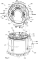
- Fig. 1 illustrates an exploded schematic diagram showing an electric motor according to one embodiment of the present invention
- Fig. 2 illustrates power modules and AC output terminals of the inverter of the electric motor
- Fig. 3 illustrates the cooling liquid flow direction of the electric motor
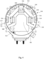
- Fig. 4 illustrates an inverter cooling liquid flow channel of the inverter of the electric motor
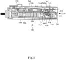
- Fig. 5 illustrates the inverter cooling liquid flow channel of the inverter of the electric motor
- Fig. 6 illustrates the inverter cooling liquid flow channel of the inverter of the electric motor
- Fig. 7 illustrates the motor main body cooling liquid flow channel of the motor main body of the electric motor.
- the electric motor 100 includes a motor main body 200 and an inverter 300.
- the inverter 300 is axially stacked on one end of the motor main body 200.
- the inverter case 310 is designed in a disk shape and directly axially connected to the motor housing 210 to eliminate an additional housing structure for supporting the inverter 300 so as to reduce the whole weight of the electric motor 100.
- the top side of the inverter case 310 is sealed by an upper cover 110, and the bottom side of the inverter case 310 is sealed to the motor housing 210 of the motor main body 200.
- the inverter 300 includes an inverter case 310, a plurality of power modules 340 and a plurality of cooling fins 314.
- the inverter case 310 includes an annular portion 311, a supporting portion 312 and a cooling liquid flow channel 400.
- the annular portion 311 includes a hollow structure axially penetrating up and down, the supporting portion 312 is arranged in the hollow structure of the annular portion 311, and the cooling liquid flow channel 400 is a sealed channel located and communicated in the annular portion 311 and the supporting portion 312.
- a cooling liquid inlet 317 and an inverter case cooling liquid flow channel outlet 313 are respectively formed at two ends of the cooling liquid flow channel 400 of the annular portion 311.
- the power modules 340 and the AC output terminals 348 are arranged along the inner edge of the annular portion 311 of the inverter case 310, and the power modules 340 is fixed on the circuit board 320, that is to say, the power modules 340 and the AC output terminals 348 are arranged annularly on a periphery of the circuit board 320, and the AC output terminals 348 are located between the power modules 340 and the inverter case 310.
- Each of the power modules 340 respectively includes a heat transfer part 341 and a plurality of cooling fins 314.
- the cooling fin 314 further includes a fin part 316 and a contact part 315.
- the power modules 340 is arranged on the supporting portion 312, and the cooling fins 314 are arranged in the cooling liquid flow channel 400, the fin part 316 of each cooling fin 314 is respectively extended and arranged inside the cooling liquid flow channel 400, and the contact part 315 of each cooling fin 314 is respectively extended to contact a heat transfer part 341 of a corresponding power module 340.
- the inverter 300 further includes a capacitor module 350, a DC bus bar 330 and a plurality of AC bus bars 370, also referring to Fig. 2 .
- the power modules 340 include a plurality of AC output terminals 348, a plurality of DC input terminals 347 and a plurality of signal terminals 349, and the AC output terminals 348 of the power modules 340 are respectively connect to the corresponding AC bus bars 370, the power modules 340 and corresponding DC input terminals 347 thereof are annularly arranged around the capacitor module 350, and the DC bus bar 330 is extended to electrically connect to corresponding DC input terminals 347 and also electrically connect the capacitor module 350 so that the power modules 340 are respectively connected in parallel with the capacitor module 350.
- the capacitor module 350 includes one capacitor or a plurality of capacitors, preferably arranged in a central area 101 surrounded by the power modules 340, so that the distances between the capacitor module 350 and the power modules 340 may more uniform.
- the capacitor module 350 may be arranged closer to the power modules 340 so as to effectively improve the working efficiency of the capacitor module 350.
- the supporting portion 312 of the inverter case 310 further includes an accommodating area 502 formed above the supporting portion 312, and the capacitor module 350 is accommodated in the accommodating area 502.
- the power modules 340, the DC bus bar 330 and the capacitor module 350 are located under the circuit board 320, and the signal terminals 349 of the power modules 340 are electrically connected to the circuit board 320, and further electrically connected to the gate driver and the control circuit.
- the cooling liquid flow channel 400 is extended to the positions corresponding to the power modules 340.
- the cooling liquid flow channel 400 surrounds the accommodating area 502, and the area of the cooling liquid flow channel 400 corresponding to the accommodating area 502 is formed by a good heat conductor, e.g. aluminum alloy, zinc alloy or magnesium alloy or the like.
- the power modules 340 is arranged on the supporting portion top surface 319.
- the supporting portion 312 further includes a plurality of passageways 318 penetrating through the supporting portion 312 up and down, and the AC bus bars 370 are extended downward through the passageways 318.
- the AC bus bars 370 includes an extended AC bus bars 372, and the motor main body 200 includes a motor coil.
- One end of each AC bus bar 370 is respectively connected to a corresponding AC output terminal 348 and another end of the AC bus bar 370 is connected to a corresponding extended AC bus bars 372, and the extended AC bus bar 372 is extended to electrically connect to the motor coil, and the extended AC bus bar 372 is upward extended to the corresponding AC bus bars 370 and the extended AC bus bar 372 is mechanically connected to the corresponding AC bus bar 370 with a fastening device, such as a screw, welding or the like.
- a fastening device such as a screw, welding or the like.
- the extended AC bus bars 372 may be extended upward through the passageways 318, and the extended AC bus bars 372 and the AC bus bars 370 are mechanically connected together at positions above the supporting portion 312 with fastening devices, such as screws, welding or the like.
- the power modules 340 include, for example, a first two-phase power module 342, a second two-phase power module 344 and a third two-phase power module 346, and the AC output terminals 348 are arranged annularly on a periphery of the circuit board 320 and the power modules 340 are arranged on an inner side of the AC output terminals 348.
- the first two-phase power module 342, the second two-phase power module 344 and the third two-phase power module 346 arranged annularly on the periphery of the circuit board 320 may reduce the influence of heat generated by the power modules 340 and the AC output terminals 348 on the electronic components of the circuit board 320.
- annular arrangement of the AC output terminals 348 of the power modules 340 is more helpful to dissipate the heat of the inverter 300, and may effectively reduce the length differences of the control signal paths therebetween so as to uniform the signal noise and conveniently eliminate the noise interference generated by the inverter 300.
- annular arrangement of the two-phase power modules on the periphery of the circuit board 320 may further simplify the circuit layout of the inverter 300 as well as simplify the components and structure of the inverter 300 and the electric motor 100.
- the DC power of the battery pack is converted from the DC power into the AC power by the power modules 340, and then outputted by way of the AC output terminals 348.
- the cooling liquid flow channel 400 of the electric motor 100 is illustrated.
- the cooling liquid of the electric motor 100 enters into the inverter 300 from the cooling liquid inlet 317 along the arrow direction 401, and then passes under the of the first two-phase power module 342 along the arrow direction 402. Subsequently, the cooling liquid passes under the second two-phase power module 344 along the arrow direction 403, and then the cooling liquid passes under the third two-phase power module 346 along the arrow direction 404 to effectively cool down the first two-phase power module 342, the second two-phase power module 344 and the third two-phase power module 346.
- the cooling liquid is discharged from the inverter case 310 through the inverter case cooling liquid flow channel outlet 313 along the arrow direction 405. Meanwhile, because that the inverter case cooling liquid flow channel outlet 313 and the motor housing cooling liquid flow channel inlet 212 are sealed together, the cooling liquid discharged from the inverter case 310 may directly enter into the motor housing 210 through the motor housing cooling liquid flow channel inlet 212 along the arrow direction 406.
- the cooling liquid circulates the motor housing 210 about one circuit along the arrow direction 407, and is discharged from the motor housing 210 through the cooling liquid outlet 216 as well as be discharged from the electric motor 100.
- the electric motor 100 adopts a single flow cooling system, so that the cooling liquid enters into the electric motor 100 from the inverter 300 to cool the power modules 340 and other electronic components in the inverter 300, then flows into the motor main body 200 to cool the components in the motor main body 200.
- the inverter 300 and the motor main body 200 share a common liquid cooling system to effectively improve the working efficiency of the entire electric motor 100 and further improve the service life of the electric motor 100.
- the inverter cooling liquid flow channel 410 of the cooling liquid flow channel 400 starts from the cooling liquid inlet 317 and ends at the inverter case cooling liquid flow channel outlet 313.
- the inverter cooling liquid flow channel 410 sequentially passes through the bottom sides of the power modules 340.
- the bottom sides of the power modules 340 are further equipped with a plurality of cooling fins 314 having the of the fin parts 316 extending into the cooling liquid flow channel 400 and the contact parts 315 respectively contacting heat transfer parts 341 of corresponding power modules 340 to enhance the cooling efficiency of the power modules 340.
- the motor housing 210 is formed by a good heat conductor.
- the inverter case 310 and the motor housing 210 are formed by aluminum alloy, zinc alloy, magnesium alloy or the like.
- the inverter case 310 and the motor housing 210 are preferably metal casings manufactured by metal processing, die casting or powder metallurgy.
- the cooling fins 314 and the inverter case 310 are integrally formed in one piece, or the cooling fins 314 and the inverter case 310 are formed separately and the cooling fins 314 are then fixed in the inverter case 310.
- the cooling fins 314 are pin type cooling fins.
- the inverter 300 further includes a cooling liquid flow channel sealing cover 360 to seal the inverter case 310 so as to allow the cooling liquid flowing in the inverter cooling liquid flow channel 410 and passing through the cooling fins 314.
- the cooling liquid flow channel sealing cover 360 is formed by metal or plastic.
- the motor main body cooling liquid flow channel 420 of the motor main body of the electric motor is illustrated.
- the cooling liquid enters from the cooling liquid inlet 317, passes through the power modules 340, the capacitor module 350 and electronic components by way of the inverter cooling liquid flow channel 410, exits the inverter case 310 by way of the inverter case cooling liquid flow channel outlet 313, and then directly enters the motor housing cooling liquid flow channel inlet 212.
- the motor main body cooling liquid flow channel 420 of the cooling liquid flow channel 400 in the motor housing 210 includes a cooling liquid entering path 217, at least one cooling liquid circulation path 218 and a cooling liquid exhausting path 219.
- the cooling liquid entering path 217, the cooling liquid circulation path 218 and the cooling liquid exhausting path 219 are formed in the motor housing 210 in sequence.
- the motor housing cooling liquid flow channel inlet 212 is communication with the cooling liquid entering path 217, and the cooling liquid exhausting path 219 is communication with the cooling liquid outlet 216.
- the cooling liquid may circulate the motor housing 210 along the motor main body cooling liquid flow channel 420 and exit the motor housing 210 from the cooling liquid outlet 216.
- the motor main body cooling liquid flow channel 420 starts from motor housing cooling liquid flow channel inlet 212, and ends at the cooling liquid outlet 216.
- the cooling liquid enters the motor housing 210 from the motor housing cooling liquid flow channel inlet 212
- the cooling liquid is guided by the cooling liquid inlet guide plate 213 to enter the cooling liquid entering path 217 and flow downward along the arrow direction 421, and then guided by the cooling liquid circulation paths 218, i.e. horizontal cooling liquid paths, formed by a plurality of cooling liquid horizontal guide plates 214 along the arrow direction 422 to the right side of Fig. 7 .
- the cooling liquid may circulate in the motor housing 210 at least in a C-shaped circulation to reach the cooling liquid outlet 216 along the arrow direction 423, and the cooling liquid exhausting path 219 formed by the cooling liquid outlet guide plate 215 may form a discharge path to guide the cooling liquid to the cooling liquid outlet 216, and exits the motor housing 210 along the arrow direction 424.
- the motor main body cooling liquid flow channel 420 includes a plurality of cooling liquid circulation paths 218 parallel with each other to circulate in the motor housing 210, and two ends of the cooling liquid circulation paths 218 are respectively communicated with the cooling liquid entering path 217 and the cooling liquid exhausting path 219. It is worth noting that the cooling liquid entering path 217 is adjacent to the cooling liquid exhausting path 219, and the cooling liquid entering path 217 and the cooling liquid exhausting path 219 are separated on two sides of the cooling liquid inlet guide plate 213 and/or the cooling liquid outlet guide plate 215 to guide the cooling liquid to circulate in the motor housing 210 with a C-shaped circulation along the arrow direction 422, and then discharge from the motor housing 210.
- the inverter case 310 is detachably coupled to the motor housing top end 211 with a mechanical connection.
- the motor housing top end 211 is corresponding to the inverter case bottom end 301 of the inverter case 310.
- the circuit board 320 is a driving circuit such as an integral circuit board having a gate driver and a control circuit so as to effectively simplify the assembly structure of the inverter 300, thereby improving the manufacturing efficiency of the inverter 300 and the electric motor 100.
- the motor housing 210 of the motor main body 200 and the inverter case 310 of the inverter 300 are made of metal materials to improve the heat dissipation efficiency and the mechanical strength of the inverter 300 and the electric motor 100.
- the inverter may effectively cool the power modules and the capacitor module with the cooling liquid flow channel in the inverter case, simplify the circuit layout and reduce the influence of heat generated by the power modules and the AC output terminals on the electronic components of the circuit board with the two-phase power modules and the AC output terminals annularly arranged on a periphery of the circuit board.
- the motor main body and the inverter share the same cooling liquid, and the inverter cooling liquid outlet and the cooling liquid inlet of the motor main body are tightly sealed together to reduce the structure complexity of the electric motor.
- the cooling liquid flow channel of the motor housing is formed in a C-shaped path so that the resistance force is reduced and the cooling liquid may conveniently flow through.
- the electric motor has an inverter and a motor main body axially stacked together so as to reduce the distance extending from the motor coil to the inverter, reduce the entire volume of the whole inverter, simplify the assembly structure of the inverter and the motor main body, and therefore reduce the overall weight of the electric motor.
Landscapes
- Engineering & Computer Science (AREA)
- Power Engineering (AREA)
- Microelectronics & Electronic Packaging (AREA)
- Physics & Mathematics (AREA)
- Thermal Sciences (AREA)
- Motor Or Generator Cooling System (AREA)
Abstract
Description
- The present disclosure relates to an inverter. More particularly, the present disclosure relates to an inverter of an electric motor.
- With the advancement of science and technology in recent years, electric vehicles have become a priority industry in various countries. Electric vehicles generally use battery packs to provide power for the electric vehicles, and use inverter systems to convert direct current into alternating current with variable frequency and current to drive the electric motors of the electric vehicles. In different operating conditions, the inverter may be operated in a motor mode and a power generation mode. In the motor mode, the inverter outputs AC current to rotate the electric motor, while in the power generation mode, the electric motor uses the kinetic energy to convert the alternating current to the direct current so as to charge the battery pack to realize energy recovery.
- The inverter is an important component of the powertrain system of the electric vehicle, and plays a key role in the electric vehicle powertrain system. The inverter converts the direct current (DC) power supplied from the battery pack into alternating current (AC) power to drive the electric motor of the electric vehicle, and controls the timing changes in the switching duty cycle to adjust the AC charging frequency to control the speed of the electric motor, just like fuel injection and ignition systems play a role in the internal combustion engine. A higher speed and efficiency of the inverter can improve the overall efficiency of the electric vehicle so as to increase the endurance mileage of the battery pack of the electric vehicle. The DC-AC conversion method is to control the switching sequence of each phase switch with the switching strategy, and uses frequency and current control command or torque control command to adjust the output of the converter so as to drive the electric motor to provide speed and torque. A higher frequency may provide a higher speed of the electric motor and a higher output current may provide a stronger torque of the electric motor so that a greater kinetic energy of the electric vehicle can be provided. Therefore, a better overall efficiency of the electric vehicle, a lower discharge speed of the battery pack and an increased endurance mileage may be obtained according to a better efficiency adjustment of the electric motor.
- Generally speaking, the electric vehicle motor driving inverter will select the appropriate type of power switch element, such as Metal-Oxide-Semiconductor Field-Effect Transistor (MOSFET), Insulated Gate Bipolar Transistor (IGBT) or silicon carbide (SiC) power components, according to the operating voltage and switching frequency range. According to the voltage, current and temperature consideration, the power switching components are determined. In addition, an appropriate heat dissipation method has to be designed to reduce the heat generated by the power switching components while the electric motor driving inverter is working.
- Hence, there is a need to integrate the inverter and the electric motor, and further improve the heat dissipation efficiency of the electric motor and the inverter in the field of electric vehicles.
- The summary of the present invention is intended to provide a simplified description of the disclosure to enable readers to have a basic understanding of the disclosure. The summary of the present invention is not a complete overview of the disclosure, and it is not intended to point out the importance of the embodiments / key elements of the present invention or define the scope of the invention.
- One objective of the embodiments of the present invention is to provide an electric motor able to simplify the assembly structure of the inverter and the motor main body, reduce the overall weight of the electric motor, and integrate the cooling liquid flow channel of the inverter and the motor so as to improve the working efficiency and service life of the electric motor.
- To achieve these and other advantages and in accordance with the objective of the embodiments of the present invention, as the embodiment broadly describes herein, the embodiments of the present invention provides an inverter including an inverter case, a plurality of power modules and a plurality of cooling fins. The inverter case includes an annular portion having a hollow structure axially penetrating up and down, a supporting portion arranged in the hollow structure of the annular portion and a cooling liquid flow channel. In addition, the cooling liquid flow channel is a sealed channel located in the annular portion and the supporting portion, and a cooling liquid inlet and an inverter case cooling liquid flow channel outlet are respectively formed at two ends of the cooling liquid flow channel. Each power module includes a heat transfer part and a plurality of cooling fins, and each cooling fin respectively includes a fin part and a contact part. The power modules are arranged on the supporting portion, and the cooling fins are arranged in the cooling liquid flow channel, the fin part of the cooling fin is respectively extended and arranged in the cooling liquid flow channel, and the contact part of the cooling fin is respectively extended to contact a heat transfer part of a corresponding power module of the power modules.
- In some embodiments, the inverter further includes a capacitor module, a DC bus bar and a plurality of AC bus bars. The power modules include a plurality of AC output terminals, a plurality of DC input terminals and a plurality of signal terminals, the AC output terminals of the power modules are respectively connected to corresponding AC bus bars, the power modules and corresponding DC input terminals are annularly arranged around the capacitor module, and the DC bus bar is extended to electrically connect to the corresponding DC input terminals and electrically connect to the capacitor module so that the power modules are respectively connected in parallel with the capacitor module.
- In some embodiments, the supporting portion of the inverter case further includes an accommodating area and the capacitor module is accommodated in the accommodating area.
- In some embodiments, the cooling liquid flow channel extends to corresponding locations of the power modules.
- In some embodiments, the cooling liquid flow channel further surrounds the accommodating area, and an area of the cooling liquid flow channel corresponding to the accommodating area is formed by a good heat conductor.
- In some embodiments, the power modules are arranged on a supporting portion top surface of the supporting portion, and the supporting portion further includes a plurality of passageways penetrating through the supporting portion up and down, and the AC bus bars are extended downward through the passageways.
- According to another aspect of the present invention, an electric motor is provided. The electric motor includes a motor main body, an inverter case, a plurality of power modules and a plurality of cooling fins. The motor main body includes a motor housing. The inverter case includes an annular portion, a supporting portion and a cooling liquid flow channel. The annular portion has a hollow structure axially penetrating up and down, and the supporting portion is arranged in the hollow structure of the annular portion. In addition, the cooling liquid flow channel is a sealed channel located in the annular portion and the supporting portion, and a cooling liquid inlet and an inverter case cooling liquid flow channel outlet are respectively formed at two ends of the cooling liquid flow channel. Each power module includes a heat transfer part and a plurality of cooling fins. Each cooling fin respectively includes a fin part and a contact part. In addition, the inverter is axially stacked on the motor main body, the inverter case is arranged on a motor housing top end of the motor housing, the power modules are arranged on the supporting portion, and the cooling fins are arranged in the cooling liquid flow channel. The fin part of the each of the cooling fins is respectively extended and arranged in the cooling liquid flow channel, and the contact part of the each of the cooling fins is respectively extended to contact a heat transfer part of a corresponding power module of the power modules.
- In some embodiments, the inverter further includes a plurality of AC bus bars, and each of the AC bus bars respectively includes an extended AC bus bar. In addition, the power modules include a plurality of AC output terminals, a plurality of DC input terminals and a plurality of signal terminals, and the motor main body further includes a motor coil. Furthermore, one end of each of the AC bus bars is respectively electrically connected to a corresponding AC output terminal of the AC output terminals, and another end of the each of the AC bus bars is electrically connect to a corresponding extended AC bus bar, and the corresponding extended AC bus bar is downward extended to electrically connect to the motor coil, and the extended AC bus bar is upward extended and mechanically connected to a corresponding AC bus of the AC bus bars so as to electrically connect together.
- In some embodiments, the power modules are arranged on a supporting portion top surface of the supporting portion, the supporting portion further includes a plurality of passageways penetrating through the supporting portion up and down, the extended AC bus bars are upward extended to pass through the passageways, and the extended AC bus bars and the AC bus bars are mechanically connected together above the supporting portion.
- In some embodiments, the motor housing top end is correspondingly connected to an inverter case bottom end of the inverter case, the motor housing top end includes a cooling liquid outlet, and the cooling liquid flow channel is a sealed channel communicated in the annular portion, the supporting portion and the motor housing. In addition, the motor housing further includes a motor housing cooling liquid flow channel inlet correspondingly sealed to the inverter case cooling liquid flow channel outlet.
- In some embodiments, the cooling liquid flow channel further includes a cooling liquid entering path, at least one cooling liquid circulation path and a cooling liquid exhausting path. The cooling liquid entering path, the cooling liquid circulation path and the cooling liquid exhausting path are communicated together in sequence and formed in the motor housing, the motor housing cooling liquid flow channel inlet is communication with the cooling liquid entering path, and the cooling liquid exhausting path is communication with the cooling liquid outlet.
- In some embodiments, the electric motor further includes a plurality of cooling liquid circulation paths, the cooling liquid circulation paths surround in the motor housing in parallel, two ends of the cooling liquid circulation paths are respectively communicated with the cooling liquid entering path and the cooling liquid exhausting path, and the cooling liquid entering path and the cooling liquid exhausting path are adjacent to each other and separated on two sides of a cooling liquid inlet guide plate. In addition, a cooling liquid of the cooling liquid flow channel flows through the inverter case, the power modules and the motor housing in sequence.
- In some embodiments, the inverter case is detachably arranged and mechanically connected to the motor housing top end.
- In some embodiments, the inverter further includes a capacitor module and the power modules includes a plurality of AC output terminals, a plurality of DC input terminals and a plurality of signal terminals, wherein the AC output terminals of the power modules are respectively connected to corresponding AC bus bars, the power modules and corresponding DC input terminals are annularly arranged around the capacitor module, and the DC bus bar is extended to electrically connect to the corresponding DC input terminals and is electrically connect to the capacitor module so that the power modules are respectively connected in parallel with the capacitor module.
- In some embodiments, the supporting portion of the inverter case further includes an accommodating area and the capacitor module is accommodated in the accommodating area.
- In some embodiments, the cooling liquid flow channel extends to corresponding locations of the power modules.
- In some embodiments, the cooling liquid flow channel further surrounds the accommodating area, and an area of the cooling liquid flow channel corresponding to the accommodating area is formed by a good heat conductor.
- In some embodiments, the power modules are arranged on a supporting portion top surface of the supporting portion, and the supporting portion further includes a plurality of passageways penetrating through the supporting portion up and down, and the AC bus bars are extended downward through the passageways.
- Hence, the inverter may effectively cool the power modules and the capacitor module with the cooling liquid flow channel in the inverter case, simplify the circuit layout and reduce the influence of heat generated by the power modules and the AC output terminals on the electronic components of the circuit board with the two-phase power modules and the AC output terminals annularly arranged on a periphery of the circuit board. In addition, the motor main body and the inverter share the same cooling liquid, and the inverter cooling liquid outlet and the cooling liquid inlet of the motor main body are tightly sealed together to reduce the structure complexity of the electric motor. Furthermore, the cooling liquid flow channel of the motor housing is formed in a C-shaped path so that the resistance force is reduced and the cooling liquid may conveniently flow through. Hence, the electric motor has an inverter and a motor main body axially stacked with the inverter so as to reduce the distance extending from the motor coil to the inverter, reduce the entire volume of the whole inverter, simplify the assembly structure of the inverter and the motor main body, and therefore reduce the overall weight of the electric motor.
- The disclosure can be more fully understood by reading the following detailed description of the embodiment, with reference made to the accompanying drawings as follows:
-
Fig. 1 illustrates an exploded schematic diagram showing an electric motor according to one embodiment of the present invention; -
Fig. 2 illustrates a schematic diagram showing power modules and AC output terminals of the inverter of the electric motor ofFig. 1 ; -
Fig. 3 illustrates a schematic diagram showing the cooling liquid flow direction of the electric motor ofFig. 1 ; -
Fig. 4 illustrates a schematic bottom view showing an inverter cooling liquid flow channel of the inverter of the electric motor ofFig. 1 ; -
Fig. 5 illustrates a schematic cross-sectional view showing the inverter cooling liquid flow channel of the inverter of the electric motor ofFig. 1 ; -
Fig. 6 illustrates a schematic side view showing the inverter cooling liquid flow channel of the inverter of the electric motor ofFig. 1 ; and -
Fig. 7 illustrates a schematic diagram showing the motor main body cooling liquid flow channel of the motor main body of the electric motor ofFig. 1 . - The following is a detailed description of the embodiments in conjunction with the accompanying drawings. The structure of the recombination of components and the resulting devices with equal functions are all within the scope of this disclosure. In addition, the drawings are for illustration purposes only, and are not drawn according to the original scale. For ease of understanding, the same reference numbers are used in the drawings and the description to refer to the same or like parts.
- In addition, the terms used in the entire description and the scope of the patent application, unless otherwise specified, usually have the usual meaning of each term used in this field, in the content disclosed here and in the special content. Some terms used to describe the disclosure are discussed below or elsewhere in this specification to provide additional guidance to those skilled in the art in the disclosure.
-
Fig. 1 illustrates an exploded schematic diagram showing an electric motor according to one embodiment of the present invention,Fig. 2 illustrates power modules and AC output terminals of the inverter of the electric motor,Fig. 3 illustrates the cooling liquid flow direction of the electric motor,Fig. 4 illustrates an inverter cooling liquid flow channel of the inverter of the electric motor,Fig. 5 illustrates the inverter cooling liquid flow channel of the inverter of the electric motor,Fig. 6 illustrates the inverter cooling liquid flow channel of the inverter of the electric motor, andFig. 7 illustrates the motor main body cooling liquid flow channel of the motor main body of the electric motor. - Referring to
Fig. 1 , as shown in the drawing, theelectric motor 100 includes a motormain body 200 and aninverter 300. Theinverter 300 is axially stacked on one end of the motormain body 200. - In addition, the
inverter case 310 is designed in a disk shape and directly axially connected to themotor housing 210 to eliminate an additional housing structure for supporting theinverter 300 so as to reduce the whole weight of theelectric motor 100. The top side of theinverter case 310 is sealed by anupper cover 110, and the bottom side of theinverter case 310 is sealed to themotor housing 210 of the motormain body 200. - Also referring to
Fig. 2 , the configuration of a plurality ofpower modules 340 andAC output terminals 348 of theinverter 300 is illustrated. Thecircuit board 320 is removed therefrom in order to illustrate thepower modules 340 and theAC output terminals 348 under thecircuit board 320. As shown inFigs. 1 ,2 and3 , theinverter 300 includes aninverter case 310, a plurality ofpower modules 340 and a plurality of coolingfins 314. Theinverter case 310 includes anannular portion 311, a supportingportion 312 and a coolingliquid flow channel 400. Theannular portion 311 includes a hollow structure axially penetrating up and down, the supportingportion 312 is arranged in the hollow structure of theannular portion 311, and the coolingliquid flow channel 400 is a sealed channel located and communicated in theannular portion 311 and the supportingportion 312. In addition, a coolingliquid inlet 317 and an inverter case cooling liquidflow channel outlet 313 are respectively formed at two ends of the coolingliquid flow channel 400 of theannular portion 311. - The
power modules 340 and theAC output terminals 348 are arranged along the inner edge of theannular portion 311 of theinverter case 310, and thepower modules 340 is fixed on thecircuit board 320, that is to say, thepower modules 340 and theAC output terminals 348 are arranged annularly on a periphery of thecircuit board 320, and theAC output terminals 348 are located between thepower modules 340 and theinverter case 310. - Each of the
power modules 340 respectively includes aheat transfer part 341 and a plurality of coolingfins 314. The coolingfin 314 further includes afin part 316 and acontact part 315. Thepower modules 340 is arranged on the supportingportion 312, and the coolingfins 314 are arranged in the coolingliquid flow channel 400, thefin part 316 of each coolingfin 314 is respectively extended and arranged inside the coolingliquid flow channel 400, and thecontact part 315 of each coolingfin 314 is respectively extended to contact aheat transfer part 341 of acorresponding power module 340. - In some embodiments, simultaneously referring to
Fig. 5 , theinverter 300 further includes acapacitor module 350, aDC bus bar 330 and a plurality of AC bus bars 370, also referring toFig. 2 . In addition, thepower modules 340 include a plurality ofAC output terminals 348, a plurality ofDC input terminals 347 and a plurality ofsignal terminals 349, and theAC output terminals 348 of thepower modules 340 are respectively connect to the corresponding AC bus bars 370, thepower modules 340 and correspondingDC input terminals 347 thereof are annularly arranged around thecapacitor module 350, and theDC bus bar 330 is extended to electrically connect to correspondingDC input terminals 347 and also electrically connect thecapacitor module 350 so that thepower modules 340 are respectively connected in parallel with thecapacitor module 350. - In some embodiments, the
capacitor module 350 includes one capacitor or a plurality of capacitors, preferably arranged in acentral area 101 surrounded by thepower modules 340, so that the distances between thecapacitor module 350 and thepower modules 340 may more uniform. In addition, thecapacitor module 350 may be arranged closer to thepower modules 340 so as to effectively improve the working efficiency of thecapacitor module 350. - In some embodiments, as illustrated in the cross-sectional view of the inverter cooling liquid flow channel of
Fig. 5 , the supportingportion 312 of theinverter case 310 further includes anaccommodating area 502 formed above the supportingportion 312, and thecapacitor module 350 is accommodated in theaccommodating area 502. - In some embodiments, the
power modules 340, theDC bus bar 330 and thecapacitor module 350 are located under thecircuit board 320, and thesignal terminals 349 of thepower modules 340 are electrically connected to thecircuit board 320, and further electrically connected to the gate driver and the control circuit. - In some embodiments, the cooling
liquid flow channel 400 is extended to the positions corresponding to thepower modules 340. Preferably, the coolingliquid flow channel 400 surrounds theaccommodating area 502, and the area of the coolingliquid flow channel 400 corresponding to theaccommodating area 502 is formed by a good heat conductor, e.g. aluminum alloy, zinc alloy or magnesium alloy or the like. - In some embodiments, the
power modules 340 is arranged on the supporting portiontop surface 319. In addition, referring toFig. 3 , the supportingportion 312 further includes a plurality ofpassageways 318 penetrating through the supportingportion 312 up and down, and the AC bus bars 370 are extended downward through thepassageways 318. - In some embodiments, the AC bus bars 370 includes an extended AC bus bars 372, and the motor
main body 200 includes a motor coil. One end of eachAC bus bar 370 is respectively connected to a correspondingAC output terminal 348 and another end of theAC bus bar 370 is connected to a corresponding extended AC bus bars 372, and the extendedAC bus bar 372 is extended to electrically connect to the motor coil, and the extendedAC bus bar 372 is upward extended to the corresponding AC bus bars 370 and the extendedAC bus bar 372 is mechanically connected to the correspondingAC bus bar 370 with a fastening device, such as a screw, welding or the like. - In some embodiments, the extended AC bus bars 372 may be extended upward through the
passageways 318, and the extended AC bus bars 372 and the AC bus bars 370 are mechanically connected together at positions above the supportingportion 312 with fastening devices, such as screws, welding or the like. - In some embodiments, the
power modules 340 include, for example, a first two-phase power module 342, a second two-phase power module 344 and a third two-phase power module 346, and theAC output terminals 348 are arranged annularly on a periphery of thecircuit board 320 and thepower modules 340 are arranged on an inner side of theAC output terminals 348. - The first two-
phase power module 342, the second two-phase power module 344 and the third two-phase power module 346 arranged annularly on the periphery of thecircuit board 320 may reduce the influence of heat generated by thepower modules 340 and theAC output terminals 348 on the electronic components of thecircuit board 320. - In addition, the annular arrangement of the
AC output terminals 348 of thepower modules 340 is more helpful to dissipate the heat of theinverter 300, and may effectively reduce the length differences of the control signal paths therebetween so as to uniform the signal noise and conveniently eliminate the noise interference generated by theinverter 300. - In addition, the annular arrangement of the two-phase power modules on the periphery of the
circuit board 320 may further simplify the circuit layout of theinverter 300 as well as simplify the components and structure of theinverter 300 and theelectric motor 100. - Therefore, the DC power of the battery pack is converted from the DC power into the AC power by the
power modules 340, and then outputted by way of theAC output terminals 348. - When converting direct current into alternating current, a large amount of heat will be generated by the
power modules 340, and excessive temperature may therefore affect the working efficiency and service life of theinverter 300. In addition, when theelectric motor 100 is operating, the rotating rotor and the variating magnetic field may also generate heat. During a long time high temperature operation, the high temperature may affect the insulation performance inside the electric motor and the service life of the bearings. Therefore, there is a need to reduce the operating temperature of theinverter 300 and the motormain body 200 when theelectric motor 100 is working, so as to improve the working efficiency and the service life of theinverter 300 and theelectric motor 100. - Simultaneously referring to
Figs 3 to 7 , the coolingliquid flow channel 400 of theelectric motor 100 is illustrated. InFig. 3 , the cooling liquid of theelectric motor 100 enters into theinverter 300 from the coolingliquid inlet 317 along thearrow direction 401, and then passes under the of the first two-phase power module 342 along thearrow direction 402. Subsequently, the cooling liquid passes under the second two-phase power module 344 along thearrow direction 403, and then the cooling liquid passes under the third two-phase power module 346 along thearrow direction 404 to effectively cool down the first two-phase power module 342, the second two-phase power module 344 and the third two-phase power module 346. - In addition, the cooling liquid is discharged from the
inverter case 310 through the inverter case cooling liquidflow channel outlet 313 along thearrow direction 405. Meanwhile, because that the inverter case cooling liquidflow channel outlet 313 and the motor housing cooling liquidflow channel inlet 212 are sealed together, the cooling liquid discharged from theinverter case 310 may directly enter into themotor housing 210 through the motor housing cooling liquidflow channel inlet 212 along thearrow direction 406. - Furthermore, the cooling liquid circulates the
motor housing 210 about one circuit along thearrow direction 407, and is discharged from themotor housing 210 through the coolingliquid outlet 216 as well as be discharged from theelectric motor 100. - Therefore, the
electric motor 100 adopts a single flow cooling system, so that the cooling liquid enters into theelectric motor 100 from theinverter 300 to cool thepower modules 340 and other electronic components in theinverter 300, then flows into the motormain body 200 to cool the components in the motormain body 200. Theinverter 300 and the motormain body 200 share a common liquid cooling system to effectively improve the working efficiency of the entireelectric motor 100 and further improve the service life of theelectric motor 100. - Referring to
Figs. 4 and5 , as shown in the drawings, the inverter coolingliquid flow channel 410 of the coolingliquid flow channel 400 starts from the coolingliquid inlet 317 and ends at the inverter case cooling liquidflow channel outlet 313. The inverter coolingliquid flow channel 410 sequentially passes through the bottom sides of thepower modules 340. In addition, in the flow channel of theinverter case 310, the bottom sides of thepower modules 340 are further equipped with a plurality of coolingfins 314 having the of thefin parts 316 extending into the coolingliquid flow channel 400 and thecontact parts 315 respectively contactingheat transfer parts 341 ofcorresponding power modules 340 to enhance the cooling efficiency of thepower modules 340. - In some embodiments, the
motor housing 210 is formed by a good heat conductor. - In some embodiments, the
inverter case 310 and themotor housing 210 are formed by aluminum alloy, zinc alloy, magnesium alloy or the like. - In some embodiments, the
inverter case 310 and themotor housing 210 are preferably metal casings manufactured by metal processing, die casting or powder metallurgy. - In some embodiments, the cooling
fins 314 and theinverter case 310 are integrally formed in one piece, or the coolingfins 314 and theinverter case 310 are formed separately and the coolingfins 314 are then fixed in theinverter case 310. - In some embodiments, the cooling
fins 314 are pin type cooling fins. - In some embodiments, the
inverter 300 further includes a cooling liquid flowchannel sealing cover 360 to seal theinverter case 310 so as to allow the cooling liquid flowing in the inverter coolingliquid flow channel 410 and passing through the coolingfins 314. In addition, the cooling liquid flowchannel sealing cover 360 is formed by metal or plastic. - Referring to
Fig. 6 and7 , the motor main body coolingliquid flow channel 420 of the motor main body of the electric motor is illustrated. As shown in the drawings, the cooling liquid enters from the coolingliquid inlet 317, passes through thepower modules 340, thecapacitor module 350 and electronic components by way of the inverter coolingliquid flow channel 410, exits theinverter case 310 by way of the inverter case cooling liquidflow channel outlet 313, and then directly enters the motor housing cooling liquidflow channel inlet 212. - In some embodiments, the motor main body cooling
liquid flow channel 420 of the coolingliquid flow channel 400 in themotor housing 210 includes a cooling liquid entering path 217, at least one coolingliquid circulation path 218 and a cooling liquidexhausting path 219. The cooling liquid entering path 217, the coolingliquid circulation path 218 and the cooling liquidexhausting path 219 are formed in themotor housing 210 in sequence. The motor housing cooling liquidflow channel inlet 212 is communication with the cooling liquid entering path 217, and the cooling liquidexhausting path 219 is communication with the coolingliquid outlet 216. - Hence, the cooling liquid may circulate the
motor housing 210 along the motor main body coolingliquid flow channel 420 and exit themotor housing 210 from the coolingliquid outlet 216. - Particularly referring to
Fig. 7 , as shown in the drawing, the motor main body coolingliquid flow channel 420 starts from motor housing cooling liquidflow channel inlet 212, and ends at the coolingliquid outlet 216. When the cooling liquid enters themotor housing 210 from the motor housing cooling liquidflow channel inlet 212, the cooling liquid is guided by the cooling liquidinlet guide plate 213 to enter the cooling liquid entering path 217 and flow downward along the arrow direction 421, and then guided by the coolingliquid circulation paths 218, i.e. horizontal cooling liquid paths, formed by a plurality of cooling liquidhorizontal guide plates 214 along thearrow direction 422 to the right side ofFig. 7 . The cooling liquid may circulate in themotor housing 210 at least in a C-shaped circulation to reach the coolingliquid outlet 216 along thearrow direction 423, and the cooling liquidexhausting path 219 formed by the cooling liquidoutlet guide plate 215 may form a discharge path to guide the cooling liquid to the coolingliquid outlet 216, and exits themotor housing 210 along thearrow direction 424. - In some embodiments, the motor main body cooling
liquid flow channel 420 includes a plurality of coolingliquid circulation paths 218 parallel with each other to circulate in themotor housing 210, and two ends of the coolingliquid circulation paths 218 are respectively communicated with the cooling liquid entering path 217 and the cooling liquidexhausting path 219. It is worth noting that the cooling liquid entering path 217 is adjacent to the cooling liquidexhausting path 219, and the cooling liquid entering path 217 and the cooling liquidexhausting path 219 are separated on two sides of the cooling liquidinlet guide plate 213 and/or the cooling liquidoutlet guide plate 215 to guide the cooling liquid to circulate in themotor housing 210 with a C-shaped circulation along thearrow direction 422, and then discharge from themotor housing 210. - In some embodiments, the
inverter case 310 is detachably coupled to the motor housingtop end 211 with a mechanical connection. In addition, the motor housingtop end 211 is corresponding to the inverter casebottom end 301 of theinverter case 310. - In some embodiments, the
circuit board 320 is a driving circuit such as an integral circuit board having a gate driver and a control circuit so as to effectively simplify the assembly structure of theinverter 300, thereby improving the manufacturing efficiency of theinverter 300 and theelectric motor 100. - In some embodiments, the
motor housing 210 of the motormain body 200 and theinverter case 310 of theinverter 300 are made of metal materials to improve the heat dissipation efficiency and the mechanical strength of theinverter 300 and theelectric motor 100. - Accordingly, the inverter may effectively cool the power modules and the capacitor module with the cooling liquid flow channel in the inverter case, simplify the circuit layout and reduce the influence of heat generated by the power modules and the AC output terminals on the electronic components of the circuit board with the two-phase power modules and the AC output terminals annularly arranged on a periphery of the circuit board. In addition, the motor main body and the inverter share the same cooling liquid, and the inverter cooling liquid outlet and the cooling liquid inlet of the motor main body are tightly sealed together to reduce the structure complexity of the electric motor. Furthermore, the cooling liquid flow channel of the motor housing is formed in a C-shaped path so that the resistance force is reduced and the cooling liquid may conveniently flow through. Hence, the electric motor has an inverter and a motor main body axially stacked together so as to reduce the distance extending from the motor coil to the inverter, reduce the entire volume of the whole inverter, simplify the assembly structure of the inverter and the motor main body, and therefore reduce the overall weight of the electric motor.
Claims (15)
- An inverter (300), characterized by comprising:
an inverter case (310), comprising:an annular portion (311) having a hollow structure axially penetrating up and down;a supporting portion (312) arranged in the hollow structure of the annular portion (311); anda cooling liquid flow channel (400), wherein the cooling liquid flow channel (400) is a sealed channel located in the annular portion (311) and the supporting portion (312), and a cooling liquid inlet (317) and an inverter case cooling liquid flow channel outlet (313) are respectively formed at two ends of the cooling liquid flow channel (400);a plurality of power modules (340), each of the power modules (340) comprising a heat transfer part (341); anda plurality of cooling fins (314), each of the cooling fins (314) respectively comprising a fin part (316) and a contact part (315),wherein the power modules (340) are arranged on the supporting portion (312), and the cooling fins (314) are arranged in the cooling liquid flow channel (400), the fin part (316) of the each of the cooling fins (314) is respectively extended and arranged in the cooling liquid flow channel (400), and the contact part (315) of the each of the cooling fins (314) is respectively extended to contact a heat transfer part (341) of a corresponding power module of the power modules (340). - The inverter (300) of claim 1, wherein the inverter (300) further comprises:a capacitor module (350);a DC bus bar (330); anda plurality of AC bus bars (370), wherein the power modules (340) comprise a plurality of AC output terminals (348), a plurality of DC input terminals (347) and a plurality of signal terminals (349), the AC output terminals (348) of the power modules (340) are respectively connected to corresponding AC bus bars (370), the power modules (340) and corresponding DC input terminals (347) are annularly arranged around the capacitor module (350), and the DC bus bar (330) is extended to electrically connect to the corresponding DC input terminals (347) and electrically connect to the capacitor module (350) so that the power modules (340) are respectively connected in parallel with the capacitor module (350).
- The inverter (300) of claim 2, wherein the supporting portion (312) of the inverter case (310) further comprises an accommodating area (502) and the capacitor module (350) is accommodated in the accommodating area (502).
- The inverter (300) of claim 3, wherein the cooling liquid flow channel (400) extends to corresponding locations of the power modules (340).
- The inverter (300) of claim 4, wherein the cooling liquid flow channel (400) further surrounds the accommodating area (502), and an area of the cooling liquid flow channel (400) corresponding to the accommodating area (502) is formed by a good heat conductor.
- The inverter (300) of claim 3, wherein the power modules (340) are arranged on a supporting portion top surface of the supporting portion (312), and the supporting portion (312) further comprises a plurality of passageways (318) penetrating through the supporting portion (312) up and down, and the AC bus bars (370) are extended downward through the passageways (318).
- An electric motor (100), characterized by comprising:a motor main body (200) comprising a motor housing (210); andan inverter case (310), comprising:an annular portion (311) having a hollow structure axially penetrating up and down;a supporting portion (312) arranged in the hollow structure of the annular portion (311); anda cooling liquid flow channel (400), wherein the cooling liquid flow channel (400) is a sealed channel located in the annular portion (311) and the supporting portion (312), and a cooling liquid inlet (317) and an inverter case cooling liquid flow channel outlet (313) are respectively formed at two ends of the cooling liquid flow channel (400);a plurality of power modules (340), each of the power modules (340) comprising a heat transfer part (341); anda plurality of cooling fins (314), each of the cooling fins (314) respectively comprising a fin part (316) and a contact part (315), wherein the inverter (300) is axially stacked on the motor main body (200), the inverter case (310) is arranged on a motor housing top end (211) of the motor housing (210), the power modules (340) are arranged on the supporting portion (312), and the cooling fins (314) are arranged in the cooling liquid flow channel (400), wherein the fin part (316) of the each of the cooling fins (314) is respectively extended and arranged in the cooling liquid flow channel (400), and the contact part (315) of the each of the cooling fins (314) is respectively extended to contact a heat transfer part (341) of a corresponding power module of the power modules (340).
- The electric motor (100) of claim 7, wherein the inverter (300) further comprises:a plurality of AC bus bars (370), each of the AC bus bars (370) respectively comprising an extended AC bus bar, wherein the power modules (340) comprise a plurality of AC output terminals (348), a plurality of DC input terminals (347) and a plurality of signal terminals (349), and the motor main body (200) further comprises a motor coil,wherein, one end of each of the AC bus bars (370) is respectively electrically connected to a corresponding AC output terminal of the AC output terminals (348), and another end of the each of the AC bus bars (370) is electrically connect to a corresponding extended AC bus bar, and the corresponding extended AC bus bar is downward extended to electrically connect to the motor coil, and the extended AC bus bar is upward extended and mechanically connected to a corresponding AC bus of the AC bus bars (370) so as to electrically connect together.
- The electric motor (100) of claim 8, wherein the power modules (340) are arranged on a supporting portion top surface of the supporting portion (312), the supporting portion (312) further comprises a plurality of passageways (318) penetrating through the supporting portion (312) up and down, the extended AC bus bars (370) are upward extended to pass through the passageways (318), and the extended AC bus bars (370) and the AC bus bars (370) are mechanically connected together above the supporting portion (312).
- The electric motor (100) of claim 7, wherein the motor housing top end (211) is correspondingly connected to an inverter case bottom end of the inverter case (310), the motor housing top end (211) comprises a cooling liquid outlet (216), and the cooling liquid flow channel (400) is a sealed channel communicated in the annular portion (311), the supporting portion (312) and the motor housing (210),
wherein the motor housing (210) further comprises a motor housing cooling liquid flow channel inlet (212) correspondingly sealed to the inverter case cooling liquid flow channel outlet (313). - The electric motor (100) of claim 10, wherein the cooling liquid flow channel (400) further comprises:a cooling liquid entering path (217);at least one cooling liquid circulation path (218); anda cooling liquid exhausting path (219),wherein the cooling liquid entering path (217), the cooling liquid circulation path (218) and the cooling liquid exhausting path (219) are communicated together in sequence and formed in the motor housing (210), the motor housing cooling liquid flow channel inlet (212) is communication with the cooling liquid entering path (217), and the cooling liquid exhausting path (219) is communication with the cooling liquid outlet (216).
- The electric motor (100) of claim 11, further comprising a plurality of cooling liquid circulation paths (218), wherein the cooling liquid circulation paths (218) surround in the motor housing (210) in parallel, two ends of the cooling liquid circulation paths (218) are respectively communicated with the cooling liquid entering path (217) and the cooling liquid exhausting path (219), and the cooling liquid entering path (217) and the cooling liquid exhausting path (219) are adjacent to each other and separated on two sides of a cooling liquid inlet (317) guide plate,
wherein a cooling liquid of the cooling liquid flow channel (400) flows through the inverter case (310), the power modules (340) and the motor housing (210) in sequence. - The electric motor (100) of claim 10, wherein the inverter case (310) is detachably arranged and mechanically connected to the motor housing top end (211).
- The electric motor (100) of claim 8, wherein the inverter (300) further comprises a capacitor module (350) and a DC bus bar (330), and the power modules (340) comprises a plurality of AC output terminals (348), a plurality of DC input terminals (347) and a plurality of signal terminals (349), wherein the AC output terminals (348) of the power modules (340) are respectively connected to corresponding AC bus bars (370), the power modules (340) and corresponding DC input terminals (347) are annularly arranged around the capacitor module (350), and the DC bus bar (330) is extended to electrically connect to the corresponding DC input terminals (347) and is electrically connect to the capacitor module (350) so that the power modules (340) are respectively connected in parallel with the capacitor module (350).
- The electric motor (100) of claim 14, wherein the supporting portion (312) of the inverter case (310) further comprises an accommodating area (502) and the capacitor module (350) is accommodated in the accommodating area (502), wherein the cooling liquid flow channel (400) extends to corresponding locations of the power modules (340), wherein the cooling liquid flow channel (400) further surrounds the accommodating area (502), and an area of the cooling liquid flow channel (400) corresponding to the accommodating area (502) is formed by a good heat conductor, wherein the power modules (340) are arranged on a supporting portion top surface of the supporting portion (312), and the supporting portion (312) further comprises a plurality of passageways (318) penetrating through the supporting portion (312) up and down, and the AC bus bars (370) are extended downward through the passageways (318).
Applications Claiming Priority (1)
| Application Number | Priority Date | Filing Date | Title |
|---|---|---|---|
| CN202310210245.6A CN118631073A (en) | 2023-03-07 | 2023-03-07 | Inverter and electric motor having the same |
Publications (1)
| Publication Number | Publication Date |
|---|---|
| EP4429430A1 true EP4429430A1 (en) | 2024-09-11 |
Family
ID=89619306
Family Applications (1)
| Application Number | Title | Priority Date | Filing Date |
|---|---|---|---|
| EP24151303.5A Pending EP4429430A1 (en) | 2023-03-07 | 2024-01-11 | Inverter and electric motor with the same |
Country Status (3)
| Country | Link |
|---|---|
| US (1) | US20240305170A1 (en) |
| EP (1) | EP4429430A1 (en) |
| CN (1) | CN118631073A (en) |
Citations (3)
| Publication number | Priority date | Publication date | Assignee | Title |
|---|---|---|---|---|
| US20140239755A1 (en) * | 2011-11-10 | 2014-08-28 | Kabushiki Kaisha Yaskawa Denki | Rotating electrical machine |
| US20210257883A1 (en) * | 2018-06-15 | 2021-08-19 | Lg Electronics Inc. | Drive system for electric automobile |
| EP3944476A1 (en) * | 2020-07-22 | 2022-01-26 | Mahle International GmbH | Inverter and electric motor comprising an inverter of this type |
Family Cites Families (3)
| Publication number | Priority date | Publication date | Assignee | Title |
|---|---|---|---|---|
| JP4797077B2 (en) * | 2009-02-18 | 2011-10-19 | 株式会社日立製作所 | Semiconductor power module, power converter, and method for manufacturing semiconductor power module |
| JP5846854B2 (en) * | 2011-10-31 | 2016-01-20 | 日立オートモティブシステムズ株式会社 | Integrated power converter and DCDC converter used therefor |
| JP5978324B2 (en) * | 2015-01-21 | 2016-08-24 | 日立オートモティブシステムズ株式会社 | Power converter |
-
2023
- 2023-03-07 CN CN202310210245.6A patent/CN118631073A/en active Pending
- 2023-07-26 US US18/358,967 patent/US20240305170A1/en active Pending
-
2024
- 2024-01-11 EP EP24151303.5A patent/EP4429430A1/en active Pending
Patent Citations (3)
| Publication number | Priority date | Publication date | Assignee | Title |
|---|---|---|---|---|
| US20140239755A1 (en) * | 2011-11-10 | 2014-08-28 | Kabushiki Kaisha Yaskawa Denki | Rotating electrical machine |
| US20210257883A1 (en) * | 2018-06-15 | 2021-08-19 | Lg Electronics Inc. | Drive system for electric automobile |
| EP3944476A1 (en) * | 2020-07-22 | 2022-01-26 | Mahle International GmbH | Inverter and electric motor comprising an inverter of this type |
Also Published As
| Publication number | Publication date |
|---|---|
| US20240305170A1 (en) | 2024-09-12 |
| CN118631073A (en) | 2024-09-10 |
Similar Documents
| Publication | Publication Date | Title |
|---|---|---|
| JP5439309B2 (en) | Power converter | |
| US9210834B2 (en) | Power converter | |
| US9877419B2 (en) | Power conversion apparatus | |
| EP3493387B1 (en) | Power inverter | |
| US10291148B2 (en) | Power conversion apparatus | |
| JP4305537B2 (en) | Power converter | |
| US10319665B2 (en) | Cooler and cooler fixing method | |
| KR102532313B1 (en) | Hybrid power control unit for vehicle | |
| JP7113937B1 (en) | power converter | |
| CN113329587A (en) | Power conversion device | |
| US20240032265A1 (en) | Power card | |
| JP7214028B1 (en) | power converter | |
| US20240305170A1 (en) | Inverter and electric motor with the same | |
| US12556106B2 (en) | Electric power conversion device | |
| TWI857512B (en) | Inverter and electric motor with the same | |
| EP4429087A1 (en) | Electric motor | |
| JP2022021177A (en) | Power conversion device | |
| CN223206993U (en) | Inverter | |
| US20250234497A1 (en) | Inverter device, electric drive and vehicle | |
| JP7306297B2 (en) | power conversion unit | |
| JP2024170924A (en) | Power Conversion Module | |
| CN116209208A (en) | Power conversion device |
Legal Events
| Date | Code | Title | Description |
|---|---|---|---|
| PUAI | Public reference made under article 153(3) epc to a published international application that has entered the european phase |
Free format text: ORIGINAL CODE: 0009012 |
|
| STAA | Information on the status of an ep patent application or granted ep patent |
Free format text: STATUS: THE APPLICATION HAS BEEN PUBLISHED |
|
| AK | Designated contracting states |
Kind code of ref document: A1 Designated state(s): AL AT BE BG CH CY CZ DE DK EE ES FI FR GB GR HR HU IE IS IT LI LT LU LV MC ME MK MT NL NO PL PT RO RS SE SI SK SM TR |
|
| STAA | Information on the status of an ep patent application or granted ep patent |
Free format text: STATUS: REQUEST FOR EXAMINATION WAS MADE |
|
| 17P | Request for examination filed |
Effective date: 20241028 |
|
| RBV | Designated contracting states (corrected) |
Designated state(s): AL AT BE BG CH CY CZ DE DK EE ES FI FR GB GR HR HU IE IS IT LI LT LU LV MC ME MK MT NL NO PL PT RO RS SE SI SK SM TR |