EP4429409A1 - Identification and compensation of anomalies and errors in a lighting system - Google Patents
Identification and compensation of anomalies and errors in a lighting system Download PDFInfo
- Publication number
- EP4429409A1 EP4429409A1 EP23160627.8A EP23160627A EP4429409A1 EP 4429409 A1 EP4429409 A1 EP 4429409A1 EP 23160627 A EP23160627 A EP 23160627A EP 4429409 A1 EP4429409 A1 EP 4429409A1
- Authority
- EP
- European Patent Office
- Prior art keywords
- led converter
- system data
- led
- converter
- anomaly
- Prior art date
- Legal status (The legal status is an assumption and is not a legal conclusion. Google has not performed a legal analysis and makes no representation as to the accuracy of the status listed.)
- Pending
Links
Images


Classifications
-
- H—ELECTRICITY
- H05—ELECTRIC TECHNIQUES NOT OTHERWISE PROVIDED FOR
- H05B—ELECTRIC HEATING; ELECTRIC LIGHT SOURCES NOT OTHERWISE PROVIDED FOR; CIRCUIT ARRANGEMENTS FOR ELECTRIC LIGHT SOURCES, IN GENERAL
- H05B45/00—Circuit arrangements for operating light-emitting diodes [LED]
- H05B45/50—Circuit arrangements for operating light-emitting diodes [LED] responsive to malfunctions or undesirable behaviour of LEDs; responsive to LED life; Protective circuits
-
- H—ELECTRICITY
- H05—ELECTRIC TECHNIQUES NOT OTHERWISE PROVIDED FOR
- H05B—ELECTRIC HEATING; ELECTRIC LIGHT SOURCES NOT OTHERWISE PROVIDED FOR; CIRCUIT ARRANGEMENTS FOR ELECTRIC LIGHT SOURCES, IN GENERAL
- H05B47/00—Circuit arrangements for operating light sources in general, i.e. where the type of light source is not relevant
- H05B47/10—Controlling the light source
- H05B47/175—Controlling the light source by remote control
-
- H—ELECTRICITY
- H05—ELECTRIC TECHNIQUES NOT OTHERWISE PROVIDED FOR
- H05B—ELECTRIC HEATING; ELECTRIC LIGHT SOURCES NOT OTHERWISE PROVIDED FOR; CIRCUIT ARRANGEMENTS FOR ELECTRIC LIGHT SOURCES, IN GENERAL
- H05B47/00—Circuit arrangements for operating light sources in general, i.e. where the type of light source is not relevant
- H05B47/20—Responsive to malfunctions or to light source life; for protection
- H05B47/21—Responsive to malfunctions or to light source life; for protection of two or more light sources connected in parallel
- H05B47/22—Responsive to malfunctions or to light source life; for protection of two or more light sources connected in parallel with communication between the lamps and a central unit
Definitions
- the present disclosure relates to the field of lighting systems, lighting management and LED converters, in particular LED converters that share a current or voltage supply with other electrical loads. More precisely, the disclosure relates to improved monitoring of system data of the lighting system, and to identification and compensation of anomalies and errors in such systems.
- automation protocols e.g., a Digital Addressable Lighting Interface (DALI) protocol
- DALI Digital Addressable Lighting Interface
- the detection of errors is however limited to those errors detectable by parameters and commands, which are supported by said automation protocols.
- the conventional lighting systems are limited to indicating the presence of single, delimited errors or faults of the LED converters.
- an objective of embodiments of the present disclosure is to improve error detection and compensation in conventional lighting systems.
- a first aspect of the present disclosure provides a system for lighting anomaly identification, comprising a first LED converter configured to obtain first system data available in the first LED converter, at least one (i.e. or more) second LED converter configured to obtain second system data available in the second LED converter, and a control device configured to identify a lighting anomaly based on the first system data and the second system data, wherein the first system data and the second system data is obtained in a sensor-less manner.
- LED converter data being determined in a sensor-less manner inside the respective LED converter, it is possible to draw conclusions about a condition in the lighting system and to react to it.
- information from several LED converters also LED converter parameters
- obtaining the first system data and the second system data in a sensor-less manner means that the first system data and the second system data are obtained without using a sensor.
- a sensor e.g. is a dedicated sensor for a single or combined measurement purpose, such as at least one of: a voltage sensor, a current sensor, a frequency sensor.
- obtaining the first system data and the second system data in a sensor-less manner means that that respective data is determined indirectly, e.g., based on other data that is available inside the respective LED converter.
- control device can be comprised by an LED converter (e.g., the first LED converter or the second LED converter).
- an LED converter e.g., the first LED converter or the second LED converter.
- the lighting anomaly comprises at least one of: an error or fault in an LED converter, a deviation of a switching frequency, a deviation of an output voltage, a deviation of an output current, interference with a current or voltage source, interference with a load.
- the first system data comprises at least one of: an operating frequency of the first LED converter, an output voltage of the first LED converter, an output current of the first LED converter; and/or the second system data comprises at least one of: an operating frequency of the second LED converter, an output voltage of the second LED converter, an output current of the second LED converter.
- the operating frequency is a switching frequency of an LED converter.
- the first LED converter comprises a first sensor-less circuit configured to obtain the first system data
- the second LED converter comprises a second sensor-less circuit configured to obtain the second system data
- the first sensor-less circuit comprises at least one of: a micro-processor, an ASIC, an FPGA; and/or the second sensor-less circuit comprises at least one of: a micro-processor, an ASIC, an FPGA.
- the first LED converter is configured to transmit the first system data to the control device in a wireless or wired manner
- the second LED converter is configured to transmit the second system data to the control device in a wireless or wired manner.
- the wired manner comprises a DALI bus.
- the wireless manner comprises at least one of: WiFi, Bluetooth, LiFi, NFC.
- the first LED converter is configured to transmit only a subset of the first system data to the control unit, and/or the second LED converter is configured to transmit only a subset of the second system data to the control device.
- the first LED converter is configured to increase the subset of the first system data depending on a first anomaly condition
- the second LED converter is configured to increase the subset of the second system data depending on a second anomaly condition
- an anomaly condition comprises an indication of an anomaly or error that requires detailed analysis.
- the first LED converter is configured to transmit the first system data to the control device at a low transmission rate
- the second LED converter is configured to transmit the second system data to the control device at a low transmission rate
- the first LED converter is configured to increase the transmission rate of the first system data depending on a third anomaly condition
- the second LED converter is configured to increase the transmission rate of the second system data depending on a fourth anomaly condition.
- an anomaly condition comprises an indication of an anomaly or error that requires detailed analysis.
- control device is configured to adjust an operating parameter of the first LED converter and/or the second LED converter based on the identified lighting anomaly to compensate the lighting anomaly.
- control device is configured to: compare the first system data and the second system data; determine a deviation of at least one of: an operating frequency of the first LED converter, an output voltage of the first LED converter, an output current of the first LED converter; and to compensate the anomaly, adjust, based on the determined deviation, an operating parameter of the second LED converter.
- This provides a precise instruction of how to determine and mitigate an error.
- the deviation may be a decrease or an increase, compared to the corresponding values of the second LED converter.
- the control device is configured to control the second LED converter to LED current increasing change an operating frequency of the second LED converter, an output voltage of the second LED converter, and/or an output current of the second LED converter, so that an LED connected to the second LED converter gets brighter and compensates the decreased brightness of an LED connected to the first LED converter.
- the operating parameter of the first LED converter comprises at least one of: an operating frequency, an output voltage, an output current; and/or the operating parameter of the second LED converter comprises at least one of: an operating frequency, an output voltage, an output current.
- the first LED converter and the second LED converter are identical regarding at least one of: a converter type, a converter topology, an output power, an output load, a voltage of a supplied LED, a current of a supplied LED, a bus voltage, a switching frequency.
- a second aspect of the present disclosure provides a method for lighting anomaly identification, the method comprising the steps of obtaining, by a first LED converter, first system data available in the first LED converter, obtaining, by a second LED converter, second system data available in the second LED converter, and identifying, by a control device, a lighting anomaly based on the first system data and the second system data, wherein the first system data and the second system data is obtained in a sensor-less manner.
- the first system data comprises at least one of: an operating frequency of the first LED converter, an output voltage of the first LED converter, an output current of the first LED converter; and/or the second system data comprises at least one of: an operating frequency of the second LED converter, an output voltage of the second LED converter, an output current of the second LED converter.
- the method further comprises obtaining, by a first sensor-less circuit of the first LED converter, the first system data, and/or obtaining, by a second sensor-less circuit of the second LED converter, the second system data.
- the first sensor-less circuit comprises at least one of: a micro-processor, an ASIC, an FPGA; and/or the second sensor-less circuit comprises at least one of: a micro-processor, an ASIC, an FPGA.
- the method further comprises transmitting, by the first LED converter, the first system data to the control device in a wireless or wired manner, and/or transmitting, by the second LED converter, the second system data to the control device in a wireless or wired manner.
- the first LED converter transmits only a subset of the first system data to the control unit, and/or the second LED converter transmits only a subset of the second system data to the control device.
- the first LED converter increases the subset of the first system data depending on a first anomaly condition
- the second LED converter increases the subset of the second system data depending on a second anomaly condition
- the first LED converter transmits the first system data to the control device at a low transmission rate, and/or the second LED converter transmits the second system data to the control device at a low transmission rate.
- the first LED converter increases the transmission rate of the first system data depending on a third anomaly condition
- the second LED converter increases the transmission rate of the second system data depending on a fourth anomaly condition.
- control device adjusts an operating parameter of the first LED converter and/or the second LED converter based on the identified lighting anomaly to compensate the lighting anomaly.
- the method further comprises: comparing, by the control device, the first system data and the second system data; determining, by the control device, a deviation of at least one of: an operating frequency of the first LED converter, an output voltage of the first LED converter, an output current of the first LED converter; and to compensate the anomaly, adjusting, by the control device based on the determined deviation, an operating parameter of the second LED converter.
- the operating parameter of the first LED converter comprises at least one of: an operating frequency, an output voltage, an output current; and/or the operating parameter of the second LED converter comprises at least one of: an operating frequency, an output voltage, an output current.
- the first LED converter and the second LED converter are identical regarding at least one of: a converter type, a converter topology, an output power, an output load, a voltage of a supplied LED, a current of a supplied LED, a bus voltage, a switching frequency.
- the second aspect and its implementation forms provide the same advantages as the first aspect and its implementation forms, respectively.
- a third aspect of the present disclosure provides a computer program comprising instructions which, when the program is executed by a distributed computing system, cause the distributed computing system to carry out the steps of the method of the second aspects or any of its implementation forms.
- the third aspect and its implementation forms provide the same advantages as the first aspect and its implementation forms, respectively.
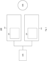
- FIG. 1 shows a system 100 for lighting anomaly identification.
- the system 100 in particular can be a lighting system, e.g., a DALI based lighting system.
- the system 100 comprises a first LED converter 101.
- the first LED converter is configured to obtain first system data 102 available in the first LED converter 101.
- the system 100 further comprises a second LED converter 103 that is configured to obtain second system data 104 available in the second LED converter 103.
- the system 100 further comprises a control device 105 that is configured to identify a lighting anomaly 106 based on the first system data 102 and the second system data 104.
- the first system data 102 and the second system data 104 are obtained in a sensor-less manner.
- the sensor-less manner may include that the first system data 102 and the second system data 104 is obtained without using a sensor, e.g., a dedicated sensor for a single or combined measurement purpose.
- a sensor e.g., a dedicated sensor for a single or combined measurement purpose.
- the control device 105 can be comprised by an LED converter (e.g., the first LED converter 101 or the second LED converter 103).
- the lighting anomaly e.g., may comprises an error or fault in an LED converter, a deviation of a switching frequency, a deviation of an output voltage, a deviation of an output current, interference with a current or voltage source, interference with a load.
- Converter parameters can be used as a basis for inferences in the system 100 and can be reacted to, if necessary.
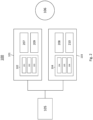
- the system 100 is now going to be described in more detail in view of FIG. 2 .
- the system 100 of FIG. 2 includes all functions and features of the system 100 as described in view of FIG. 1 .
- the first system data 102 optionally may comprise at least one of an operating frequency 201 of the first LED converter 101, an output voltage 202 of the first LED converter 101, or an output current 203 of the first LED converter 101.
- the second system data 104 may comprise at least one of an operating frequency 204 of the second LED converter 103, an output voltage 205 of the second LED converter 103, or an output current 206 of the second LED converter 103.
- the first LED converter 101 can comprise a first sensor-less circuit 207.
- the first sensor-less circuit 207 may obtain the first system data 102.
- the second LED converter 103 may comprise a second sensor-less circuit 208, which may obtain the second system data 104.
- the first sensor-less circuit 207 may comprise at least one of a micro-processor, an ASIC, or an FPGA.
- the second sensor-less circuit 208 may comprise at least one of a micro-processor, an ASIC, or an FPGA.
- the first LED converter 101 can be configured to transmit the first system data 102 to the control device 105 in a wireless or wired manner.
- the second LED converter 103 can be configured to transmit the second system data 104 to the control device 105 in a wireless or wired manner.
- the first LED converter 101 may only transmit a subset 209 of the first system data 102 to the control unit.
- the second LED converter 103 may only transmit a subset 210 of the second system data 104 to the control device 105.
- the first LED converter 101 can increase the subset 209 of the first system data 102 depending on a first anomaly condition.
- the second LED converter 103 can increase the subset 210 of the second system data 104 depending on a second anomaly condition.
- the first LED converter 101 can transmit the first system data 102 to the control device 105 at a low transmission rate.
- the second LED converter 103 is configured to transmit the second system data 104 to the control device 105 at a low transmission rate.
- the first LED converter 101 may increase the transmission rate of the first system data 102 depending on a third anomaly condition.
- the second LED converter 103 may increase the transmission rate of the second system data 104 depending on a fourth anomaly condition.
- control device 105 can adjust an operating parameter of the first LED converter 101 and/or the second LED converter 103) based on the identified lighting anomaly 106 to compensate the lighting anomaly 106.
- control device 105 can compare the first system data 102 and the second system data 104 to determine a deviation of at least one of: an operating frequency of the first LED converter 101, an output voltage of the first LED converter 101, an output current of the first LED converter 101. The control device 105 then can compensate the anomaly 106 by adjusting, based on the determined deviation, an operating parameter of the second LED converter 103.
- the operating parameter of the first LED converter 101 which is to be adjusted, comprises an operating frequency, an output voltage, and/or an output current.
- the to be adjusted operating parameter of the second LED converter 103 comprises an operating frequency, an output voltage, and/or an output current.
- the first LED converter 101 and the second LED converter 103 can be identical regarding at least one of: a converter type, a converter topology, an output power, an output load, a voltage of a supplied LED, a current of a supplied LED, a bus voltage, a switching frequency.
- FIG. 3 shows another schematic view of the system 100 according to the present disclosure.
- the data from multiple LED converters can be regarded as system data.
- processing the system data e.g., by a control device or by an LED converter itself
- system system also in a larger sense by considering participants on a same power line
- FIG. 4 shows a schematic view of an operating example of the system 100, which is about maintaining constant light, in case of an error (that is, a lighting anomaly 106).
- a control device 105 can that a luminaire comprising a first LED converter 101 in a system 100 is getting weaker (by checking/comparing a parameter, e.g., the converter is in limitation with the switching frequency). In order to maintain illumination, the weakening must be intercepted. This can be realized by the control device 105 dimming a value of the other floor lamp comprising a second LED converter 103 (i.e., by making the floor lamp brighter).
- the first LED converter 101 for the ceiling lights gets weaker (because of a problem of the converter) and a control device 105 (or the LED converter themselves) can detect that (e.g. by checking dedicated converter parameters like the switching frequency of the current source).
- dedicated converter parameters like the switching frequency of the current source.
- the system 100 determines the actual LED current of the ceiling lights (in an LLC current source LED converter). By comparing the determined value with the set value, a difference of the LED current and consequently light output can be evaluated. To compensate the weaker light output the floor lamp can be switched on at a dedicated higher dim level.
- a machine on one string has a problem, this can have an effect on the power consumption on that string. This in turn can lower the voltage of a string. This drop can be stored in the system data of an LED converter 101 as a warning (e.g., minimum input voltage reached). If a control device 105 reads several LED converters 101, 103 from different strings and compares the warnings, the control device 105 can detect a system abnormality and draw conclusions, allowing a user to localize problems and make adjustments.
- a warning e.g., minimum input voltage reached
- LED converter parameters should be similar to each other.
- a control device 105 can read all "similar" LED converters and compare relevant parameters. If e.g., a BUS voltage (output voltage of the PFC) of an LED converter 101 is too low then this may indicate a fault of the PFC stage in this device (a mains input voltage can be neglected since the "similar" LED converter has a nominal BUS voltage, and that the problem is specific to one device).
- a BUS voltage output voltage of the PFC
- FIG. 6 shows a method 600 for lighting anomaly identification, the method 600 comprising a first step of obtaining 601, by a first LED converter 101, first system data 102 available in the first LED converter 101.
- the method 600 comprises a second step of obtaining 602, by a second LED converter 103 second system data 104 available in the second LED converter 103,
- the method 600 comprises a third step of identifying 603, by a control device 105, a lighting anomaly 106 based on the first system data 102 and the second system data 104, wherein the first system data 102 and the second system data 104 is obtained in a sensor-less manner.
Landscapes
- Circuit Arrangement For Electric Light Sources In General (AREA)
Abstract
Description
- The present disclosure relates to the field of lighting systems, lighting management and LED converters, in particular LED converters that share a current or voltage supply with other electrical loads. More precisely, the disclosure relates to improved monitoring of system data of the lighting system, and to identification and compensation of anomalies and errors in such systems.
- In conventional lighting systems, automation protocols (e.g., a Digital Addressable Lighting Interface (DALI) protocol) can be monitored to detect errors (e.g., lamp faults) in the lighting system and to respond to these errors. The detection of errors is however limited to those errors detectable by parameters and commands, which are supported by said automation protocols. Moreover, the conventional lighting systems are limited to indicating the presence of single, delimited errors or faults of the LED converters.
- Therefore, there is a need for improved error detection and mitigation in lighting systems.
- In view of the above-mentioned problem, an objective of embodiments of the present disclosure is to improve error detection and compensation in conventional lighting systems.
- This or other objectives may be achieved by embodiments of the present disclosure as described in the enclosed independent claims. Advantageous implementations of embodiments of the present disclosure are further defined in the dependent claims.
- A first aspect of the present disclosure provides a system for lighting anomaly identification, comprising a first LED converter configured to obtain first system data available in the first LED converter, at least one (i.e. or more) second LED converter configured to obtain second system data available in the second LED converter, and a control device configured to identify a lighting anomaly based on the first system data and the second system data, wherein the first system data and the second system data is obtained in a sensor-less manner.
- This ensures that, with the LED converter data being determined in a sensor-less manner inside the respective LED converter, it is possible to draw conclusions about a condition in the lighting system and to react to it. Moreover, information from several LED converters (also LED converter parameters) can be used as a basis for detecting inferences in the lighting system and can be reacted to, if necessary.
- In particular, obtaining the first system data and the second system data in a sensor-less manner means that the first system data and the second system data are obtained without using a sensor. Such a sensor e.g. is a dedicated sensor for a single or combined measurement purpose, such as at least one of: a voltage sensor, a current sensor, a frequency sensor.
- In particular, obtaining the first system data and the second system data in a sensor-less manner means that that respective data is determined indirectly, e.g., based on other data that is available inside the respective LED converter.
- In particular, the control device can be comprised by an LED converter (e.g., the first LED converter or the second LED converter).
- In particular, the lighting anomaly comprises at least one of: an error or fault in an LED converter, a deviation of a switching frequency, a deviation of an output voltage, a deviation of an output current, interference with a current or voltage source, interference with a load.
- In an implementation form of the first aspect, the first system data comprises at least one of: an operating frequency of the first LED converter, an output voltage of the first LED converter, an output current of the first LED converter; and/or the second system data comprises at least one of: an operating frequency of the second LED converter, an output voltage of the second LED converter, an output current of the second LED converter.
- This ensures that detailed system data can be gathered and analyzed by the control device. It is in particular possible to get a more detailed insight in the lighting system compared to only relying on DALI bus commands.
- In particular, the operating frequency is a switching frequency of an LED converter.
- In another implementation form of the first aspect, the first LED converter comprises a first sensor-less circuit configured to obtain the first system data, and/or the second LED converter comprises a second sensor-less circuit configured to obtain the second system data.
- This ensures that the more detailed system data can be in fact obtained inside the LED converter, without relying on e.g., a DALI bus information.
- In another implementation form of the first aspect, the first sensor-less circuit comprises at least one of: a micro-processor, an ASIC, an FPGA; and/or the second sensor-less circuit comprises at least one of: a micro-processor, an ASIC, an FPGA.
- This ensures that circuits of existing semiconductor chips can be exploited for the purpose of sensor-less obtaining of system data.
- In another implementation form of the first aspect, the first LED converter is configured to transmit the first system data to the control device in a wireless or wired manner, and/or the second LED converter is configured to transmit the second system data to the control device in a wireless or wired manner.
- This ensures that the system data can be transmitted inside a lighting system in a versatile and reliable manner.
- In particular, the wired manner comprises a DALI bus. In particular, the wireless manner comprises at least one of: WiFi, Bluetooth, LiFi, NFC.
- In another implementation form of the first aspect, the first LED converter is configured to transmit only a subset of the first system data to the control unit, and/or the second LED converter is configured to transmit only a subset of the second system data to the control device.
- This allows for increased efficiency of transmission.
- In another implementation form of the first aspect, the first LED converter is configured to increase the subset of the first system data depending on a first anomaly condition, and/or the second LED converter is configured to increase the subset of the second system data depending on a second anomaly condition.
- This ensures that transmission of system data is yet efficient but reliable and sufficient enough, if required.
- In particular, an anomaly condition comprises an indication of an anomaly or error that requires detailed analysis.
- In another implementation form of the first aspect, the first LED converter is configured to transmit the first system data to the control device at a low transmission rate, and/or the second LED converter is configured to transmit the second system data to the control device at a low transmission rate.
- This allows for increased efficiency of transmission.
- In another implementation form of the first aspect, the first LED converter is configured to increase the transmission rate of the first system data depending on a third anomaly condition, and/or the second LED converter is configured to increase the transmission rate of the second system data depending on a fourth anomaly condition.
- This ensures that transmission of system data is yet efficient but reliable and sufficient enough, if required.
- In particular, an anomaly condition comprises an indication of an anomaly or error that requires detailed analysis.
- In another implementation form of the first aspect, the control device is configured to adjust an operating parameter of the first LED converter and/or the second LED converter based on the identified lighting anomaly to compensate the lighting anomaly.
- This ensures that a lighting error cannot only be detected, but also mitigated, based on the sensor-less system data.
- In another implementation form of the first aspect, the control device is configured to: compare the first system data and the second system data; determine a deviation of at least one of: an operating frequency of the first LED converter, an output voltage of the first LED converter, an output current of the first LED converter; and to compensate the anomaly, adjust, based on the determined deviation, an operating parameter of the second LED converter.
- This provides a precise instruction of how to determine and mitigate an error.
- In particular, the deviation may be a decrease or an increase, compared to the corresponding values of the second LED converter.
- In particular, if the deviation is a decrease compared to the corresponding values of the second LED converter, the control device is configured to control the second LED converter to LED current increasing change an operating frequency of the second LED converter, an output voltage of the second LED converter, and/or an output current of the second LED converter, so that an LED connected to the second LED converter gets brighter and compensates the decreased brightness of an LED connected to the first LED converter.
- In another implementation form of the first aspect, the operating parameter of the first LED converter comprises at least one of: an operating frequency, an output voltage, an output current; and/or the operating parameter of the second LED converter comprises at least one of: an operating frequency, an output voltage, an output current.
- These are operating parameters suitable for error detection.
- In another implementation form of the first aspect, the first LED converter and the second LED converter are identical regarding at least one of: a converter type, a converter topology, an output power, an output load, a voltage of a supplied LED, a current of a supplied LED, a bus voltage, a switching frequency.
- This ensures that anomalies can be determined more precisely, since a deviating operating parameter in an otherwise identical LED converter may indicate the presence of an error.
- A second aspect of the present disclosure provides a method for lighting anomaly identification, the method comprising the steps of obtaining, by a first LED converter, first system data available in the first LED converter, obtaining, by a second LED converter, second system data available in the second LED converter, and identifying, by a control device, a lighting anomaly based on the first system data and the second system data, wherein the first system data and the second system data is obtained in a sensor-less manner.
- In an implementation form of the second aspect, the first system data comprises at least one of: an operating frequency of the first LED converter, an output voltage of the first LED converter, an output current of the first LED converter; and/or the second system data comprises at least one of: an operating frequency of the second LED converter, an output voltage of the second LED converter, an output current of the second LED converter.
- In another implementation form of the second aspect, the method further comprises obtaining, by a first sensor-less circuit of the first LED converter, the first system data, and/or obtaining, by a second sensor-less circuit of the second LED converter, the second system data.
- In another implementation form of the second aspect, the first sensor-less circuit comprises at least one of: a micro-processor, an ASIC, an FPGA; and/or the second sensor-less circuit comprises at least one of: a micro-processor, an ASIC, an FPGA.
- In another implementation form of the second aspect, the method further comprises transmitting, by the first LED converter, the first system data to the control device in a wireless or wired manner, and/or transmitting, by the second LED converter, the second system data to the control device in a wireless or wired manner.
- In another implementation form of the second aspect, the first LED converter transmits only a subset of the first system data to the control unit, and/or the second LED converter transmits only a subset of the second system data to the control device.
- In another implementation form of the second aspect, the first LED converter increases the subset of the first system data depending on a first anomaly condition, and/or the second LED converter increases the subset of the second system data depending on a second anomaly condition.
- In another implementation form of the second aspect, the first LED converter transmits the first system data to the control device at a low transmission rate, and/or the second LED converter transmits the second system data to the control device at a low transmission rate.
- In another implementation form of the second aspect, the first LED converter increases the transmission rate of the first system data depending on a third anomaly condition, and/or the second LED converter increases the transmission rate of the second system data depending on a fourth anomaly condition.
- In another implementation form of the second aspect, the control device adjusts an operating parameter of the first LED converter and/or the second LED converter based on the identified lighting anomaly to compensate the lighting anomaly.
- In another implementation form of the second aspect, the method further comprises: comparing, by the control device, the first system data and the second system data; determining, by the control device, a deviation of at least one of: an operating frequency of the first LED converter, an output voltage of the first LED converter, an output current of the first LED converter; and to compensate the anomaly, adjusting, by the control device based on the determined deviation, an operating parameter of the second LED converter.
- In another implementation form of the second aspect, the operating parameter of the first LED converter comprises at least one of: an operating frequency, an output voltage, an output current; and/or the operating parameter of the second LED converter comprises at least one of: an operating frequency, an output voltage, an output current.
- In another implementation form of the second aspect, the first LED converter and the second LED converter are identical regarding at least one of: a converter type, a converter topology, an output power, an output load, a voltage of a supplied LED, a current of a supplied LED, a bus voltage, a switching frequency.
- The second aspect and its implementation forms provide the same advantages as the first aspect and its implementation forms, respectively.
- A third aspect of the present disclosure provides a computer program comprising instructions which, when the program is executed by a distributed computing system, cause the distributed computing system to carry out the steps of the method of the second aspects or any of its implementation forms.
- The third aspect and its implementation forms provide the same advantages as the first aspect and its implementation forms, respectively.
- In the following, the invention is described exemplarily with reference to the enclosed figures, in which
- FIG. 1
- shows a schematic view of a system according to an embodiment of the present disclosure;
- FIG. 2
- shows a schematic view of a system according to an embodiment of the present disclosure in more detail;
- FIG. 3
- shows a schematic view of another system according to the present disclosure;
- FIG. 4
- shows a schematic view of an operating example according to the present disclosure;
- FIG. 5
- shows a schematic view of another operating scenario according to the present disclosure;
- FIG. 6
- shows a schematic view of a method according to an embodiment of the present disclosure.
-
FIG. 1 shows asystem 100 for lighting anomaly identification. Thesystem 100 in particular can be a lighting system, e.g., a DALI based lighting system. To allow for lighting anomaly identification, thesystem 100 comprises afirst LED converter 101. The first LED converter is configured to obtainfirst system data 102 available in thefirst LED converter 101. Thesystem 100 further comprises asecond LED converter 103 that is configured to obtainsecond system data 104 available in thesecond LED converter 103. Thesystem 100 further comprises acontrol device 105 that is configured to identify alighting anomaly 106 based on thefirst system data 102 and thesecond system data 104. Thefirst system data 102 and thesecond system data 104 are obtained in a sensor-less manner. - The sensor-less manner may include that the
first system data 102 and thesecond system data 104 is obtained without using a sensor, e.g., a dedicated sensor for a single or combined measurement purpose. Although this is not illustrated inFIG. 1 , thecontrol device 105 can be comprised by an LED converter (e.g., thefirst LED converter 101 or the second LED converter 103). - The lighting anomaly, e.g., may comprises an error or fault in an LED converter, a deviation of a switching frequency, a deviation of an output voltage, a deviation of an output current, interference with a current or voltage source, interference with a load.
- Information from several converters (also converter parameters) can be used as a basis for inferences in the
system 100 and can be reacted to, if necessary. - The
system 100 is now going to be described in more detail in view ofFIG. 2 . Thesystem 100 ofFIG. 2 includes all functions and features of thesystem 100 as described in view ofFIG. 1 . - As it is illustrated in
FIG. 2 , thefirst system data 102 optionally may comprise at least one of anoperating frequency 201 of thefirst LED converter 101, anoutput voltage 202 of thefirst LED converter 101, or anoutput current 203 of thefirst LED converter 101. Further optionally, thesecond system data 104 may comprise at least one of anoperating frequency 204 of thesecond LED converter 103, anoutput voltage 205 of thesecond LED converter 103, or anoutput current 206 of thesecond LED converter 103. - Further optionally, the
first LED converter 101 can comprise a firstsensor-less circuit 207. The firstsensor-less circuit 207 may obtain thefirst system data 102. Thesecond LED converter 103 may comprise a secondsensor-less circuit 208, which may obtain thesecond system data 104. The firstsensor-less circuit 207 may comprise at least one of a micro-processor, an ASIC, or an FPGA. The secondsensor-less circuit 208 may comprise at least one of a micro-processor, an ASIC, or an FPGA. - Further optionally, the
first LED converter 101 can be configured to transmit thefirst system data 102 to thecontrol device 105 in a wireless or wired manner. Also, thesecond LED converter 103 can be configured to transmit thesecond system data 104 to thecontrol device 105 in a wireless or wired manner. For efficiency of transmission, thefirst LED converter 101 may only transmit asubset 209 of thefirst system data 102 to the control unit. Also thesecond LED converter 103 may only transmit asubset 210 of thesecond system data 104 to thecontrol device 105. Thefirst LED converter 101 can increase thesubset 209 of thefirst system data 102 depending on a first anomaly condition. Also, thesecond LED converter 103 can increase thesubset 210 of thesecond system data 104 depending on a second anomaly condition. In an alternative or additional manner, also for efficiency reasons, thefirst LED converter 101 can transmit thefirst system data 102 to thecontrol device 105 at a low transmission rate. Also thesecond LED converter 103 is configured to transmit thesecond system data 104 to thecontrol device 105 at a low transmission rate. Thefirst LED converter 101 may increase the transmission rate of thefirst system data 102 depending on a third anomaly condition. Also thesecond LED converter 103 may increase the transmission rate of thesecond system data 104 depending on a fourth anomaly condition. - Further optionally, the
control device 105 can adjust an operating parameter of thefirst LED converter 101 and/or the second LED converter 103) based on the identifiedlighting anomaly 106 to compensate thelighting anomaly 106. - In particular, the
control device 105 can compare thefirst system data 102 and thesecond system data 104 to determine a deviation of at least one of: an operating frequency of thefirst LED converter 101, an output voltage of thefirst LED converter 101, an output current of thefirst LED converter 101. Thecontrol device 105 then can compensate theanomaly 106 by adjusting, based on the determined deviation, an operating parameter of thesecond LED converter 103. - The operating parameter of the
first LED converter 101, which is to be adjusted, comprises an operating frequency, an output voltage, and/or an output current. The to be adjusted operating parameter of thesecond LED converter 103 comprises an operating frequency, an output voltage, and/or an output current. - The
first LED converter 101 and thesecond LED converter 103 can be identical regarding at least one of: a converter type, a converter topology, an output power, an output load, a voltage of a supplied LED, a current of a supplied LED, a bus voltage, a switching frequency. -
FIG. 3 shows another schematic view of thesystem 100 according to the present disclosure. As it is illustrated, the data from multiple LED converters can be regarded as system data. By processing the system data (e.g., by a control device or by an LED converter itself) it is possible to infer system (system also in a larger sense by considering participants on a same power line) abnormalities and to react if necessary. -
FIG. 4 shows a schematic view of an operating example of thesystem 100, which is about maintaining constant light, in case of an error (that is, a lighting anomaly 106). As illustrated, acontrol device 105 can that a luminaire comprising afirst LED converter 101 in asystem 100 is getting weaker (by checking/comparing a parameter, e.g., the converter is in limitation with the switching frequency). In order to maintain illumination, the weakening must be intercepted. This can be realized by thecontrol device 105 dimming a value of the other floor lamp comprising a second LED converter 103 (i.e., by making the floor lamp brighter). - An example could be that the
first LED converter 101 for the ceiling lights gets weaker (because of a problem of the converter) and a control device 105 (or the LED converter themselves) can detect that (e.g. by checking dedicated converter parameters like the switching frequency of the current source). With e.g., the information of a PFC BUS voltage, the switching frequency and an LED voltage it is possible for thesystem 100 to determine the actual LED current of the ceiling lights (in an LLC current source LED converter). By comparing the determined value with the set value, a difference of the LED current and consequently light output can be evaluated. To compensate the weaker light output the floor lamp can be switched on at a dedicated higher dim level. - As it is going to be described in view of
FIG. 5 below, there are applications where several strings with DC voltages are distributed in parallel in a building (that is, as a DC grid). In such asystem 100, there may be one machine and several lights on each string. - If a machine on one string has a problem, this can have an effect on the power consumption on that string. This in turn can lower the voltage of a string. This drop can be stored in the system data of an
LED converter 101 as a warning (e.g., minimum input voltage reached). If acontrol device 105 readsseveral LED converters control device 105 can detect a system abnormality and draw conclusions, allowing a user to localize problems and make adjustments. - If there are several LED converters of a same type (e.g., a same topology, or a same wattage) in one room and the selected operating point (LED voltage and LED current) is similar, then the LED converter parameters should be similar to each other.
- A
control device 105 can read all "similar" LED converters and compare relevant parameters. If e.g., a BUS voltage (output voltage of the PFC) of anLED converter 101 is too low then this may indicate a fault of the PFC stage in this device (a mains input voltage can be neglected since the "similar" LED converter has a nominal BUS voltage, and that the problem is specific to one device). -
FIG. 6 shows amethod 600 for lighting anomaly identification, themethod 600 comprising a first step of obtaining 601, by afirst LED converter 101,first system data 102 available in thefirst LED converter 101. Themethod 600 comprises a second step of obtaining 602, by asecond LED converter 103second system data 104 available in thesecond LED converter 103, Themethod 600 comprises a third step of identifying 603, by acontrol device 105, alighting anomaly 106 based on thefirst system data 102 and thesecond system data 104, wherein thefirst system data 102 and thesecond system data 104 is obtained in a sensor-less manner.
Claims (15)
- A system (100) for lighting anomaly identification, comprising:- a first LED converter (101) configured to obtain first system data (102) available in the first LED converter (101),- at least one second LED converter (103) configured to obtain second system data (104) available in the second LED converter (103), and- a control device (105) configured to identify a lighting anomaly (106) based on the first system data (102) and the second system data (104),wherein the first system data (102) and the second system data (104) is obtained in a sensor-less manner.
- The system (100) according to claim 1, wherein the first system data (102) comprises at least one of:- an operating frequency (201) of the first LED converter (101),- an output voltage (202) of the first LED converter (101),- an output current (203) of the first LED converter (101); and/orwherein the second system data (104) comprises at least one of:- an operating frequency (204) of the second LED converter (103),- an output voltage (205) of the second LED converter (103),- an output current (206) of the second LED converter (103).
- The system (100) according to claim 1 or 2, wherein the first LED converter (101) comprises a first sensor-less circuit (207) configured to obtain the first system data (102), and/or wherein the second LED converter (103) comprises a second sensor-less circuit (208) configured to obtain the second system data (104).
- The system (100) according to claim 3, wherein the first sensor-less circuit (207) comprises at least one of: a micro-processor, an ASIC, an FPGA; and/or wherein the second sensor-less circuit (208) comprises at least one of: a micro-processor, an ASIC, an FPGA.
- The system (100) according to any one of the preceding claims, wherein the first LED converter (101) is configured to transmit the first system data (102) to the control device (105) in a wireless or wired manner, and/or wherein the second LED converter (103) is configured to transmit the second system data (104) to the control device (105) in a wireless or wired manner.
- The system (100) according to any one of the preceding claims, wherein the first LED converter (101) is configured to transmit only a subset (209) of the first system data (102) to the control unit, and/or wherein the second LED converter (103) is configured to transmit only a subset (210) of the second system data (104) to the control device (105).
- The system (100) according to claim 6, wherein the first LED converter (101) is configured to increase the subset (209) of the first system data (102) depending on a first anomaly condition, and/or wherein the second LED converter (103) is configured to increase the subset (210) of the second system data (104) depending on a second anomaly condition.
- The system (100) according to any one of the preceding claims, wherein the first LED converter (101) is configured to transmit the first system data (102) to the control device (105) at a low transmission rate, and/or wherein the second LED converter (103) is configured to transmit the second system data (104) to the control device (105) at a low transmission rate.
- The system (100) according to claim 8, wherein the first LED converter (101) is configured to increase the transmission rate of the first system data (102) depending on a third anomaly condition, and/or wherein the second LED converter (103) is configured to increase the transmission rate of the second system data (104) depending on a fourth anomaly condition.
- The system (100) according to any one of the preceding claims, wherein the control device (105) is configured to adjust an operating parameter of the first LED converter (101) and/or the second LED converter (103) based on the identified lighting anomaly (106) to compensate the lighting anomaly (106).
- The system (100) according to any one of the preceding claims, wherein the control device (105) is configured to:- compare the first system data (102) and the second system data (104),- determine a deviation of at least one of: an operating frequency of the first LED converter (101), an output voltage of the first LED converter (101), an output current of the first LED converter (101); and- to compensate the anomaly (106), adjust, based on the determined deviation, an operating parameter of the second LED converter (103).
- The system (100) according to claim 10 or 11, wherein the operating parameter of the first LED converter (101) comprises at least one of: an operating frequency, an output voltage, an output current; and/or wherein the operating parameter of the second LED converter (103) comprises at least one of: an operating frequency, an output voltage, an output current.
- The system (100) according to any one of the preceding claims, wherein the first LED converter (101) and the second LED converter (103) are identical regarding at least one of: a converter type, a converter topology, an output power, an output load, a voltage of a supplied LED, a current of a supplied LED, a bus voltage, a switching frequency.
- A method (600) for lighting anomaly identification, the method comprising the steps of:- obtaining (601), by a first LED converter (101), first system data (102) available in the first LED converter (101),- obtaining (602), by a second LED converter (103), second system data (104) available in the second LED converter (103), and- identifying (603), by a control device (105), a lighting anomaly (106) based on the first system data (102) and the second system data (104),wherein the first system data (102) and the second system data (104) is obtained in a sensor-less manner.
- A computer program comprising instructions which, when the program is executed by a distributed computing system, cause the distributed computing system to carry out the steps of the method (600) of claim 14.
Priority Applications (2)
| Application Number | Priority Date | Filing Date | Title |
|---|---|---|---|
| EP23160627.8A EP4429409A1 (en) | 2023-03-08 | 2023-03-08 | Identification and compensation of anomalies and errors in a lighting system |
| PCT/EP2024/055787 WO2024184374A1 (en) | 2023-03-08 | 2024-03-06 | Identification and compensation of anomalies and errors in a lighting system |
Applications Claiming Priority (1)
| Application Number | Priority Date | Filing Date | Title |
|---|---|---|---|
| EP23160627.8A EP4429409A1 (en) | 2023-03-08 | 2023-03-08 | Identification and compensation of anomalies and errors in a lighting system |
Publications (1)
| Publication Number | Publication Date |
|---|---|
| EP4429409A1 true EP4429409A1 (en) | 2024-09-11 |
Family
ID=85510799
Family Applications (1)
| Application Number | Title | Priority Date | Filing Date |
|---|---|---|---|
| EP23160627.8A Pending EP4429409A1 (en) | 2023-03-08 | 2023-03-08 | Identification and compensation of anomalies and errors in a lighting system |
Country Status (2)
| Country | Link |
|---|---|
| EP (1) | EP4429409A1 (en) |
| WO (1) | WO2024184374A1 (en) |
Citations (3)
| Publication number | Priority date | Publication date | Assignee | Title |
|---|---|---|---|---|
| WO2014121367A1 (en) * | 2013-02-05 | 2014-08-14 | Led Roadway Lighting Ltd. | Measurement and control of an outdoor light fixture |
| US20200068680A1 (en) * | 2018-08-23 | 2020-02-27 | Lumastream Canada Ulc | Data acquisition methods and apparatus for a network connected led driver |
| JP2022182448A (en) * | 2021-05-28 | 2022-12-08 | 株式会社東芝 | A/d conversion system and failure detection method for ad conversion device |
Family Cites Families (3)
| Publication number | Priority date | Publication date | Assignee | Title |
|---|---|---|---|---|
| WO2007003038A1 (en) * | 2005-06-30 | 2007-01-11 | Streetlight Intelligence, Inc. | Adaptive energy performance monitoring and control system |
| US20120268014A1 (en) * | 2009-12-16 | 2012-10-25 | Carmanah Technologies Corp. | Comparative Lighting Network |
| US20140239815A1 (en) * | 2013-02-28 | 2014-08-28 | Power One Data International, Inc. | Method and system for controlling lighting operation |
-
2023
- 2023-03-08 EP EP23160627.8A patent/EP4429409A1/en active Pending
-
2024
- 2024-03-06 WO PCT/EP2024/055787 patent/WO2024184374A1/en not_active Ceased
Patent Citations (3)
| Publication number | Priority date | Publication date | Assignee | Title |
|---|---|---|---|---|
| WO2014121367A1 (en) * | 2013-02-05 | 2014-08-14 | Led Roadway Lighting Ltd. | Measurement and control of an outdoor light fixture |
| US20200068680A1 (en) * | 2018-08-23 | 2020-02-27 | Lumastream Canada Ulc | Data acquisition methods and apparatus for a network connected led driver |
| JP2022182448A (en) * | 2021-05-28 | 2022-12-08 | 株式会社東芝 | A/d conversion system and failure detection method for ad conversion device |
Also Published As
| Publication number | Publication date |
|---|---|
| WO2024184374A1 (en) | 2024-09-12 |
Similar Documents
| Publication | Publication Date | Title |
|---|---|---|
| US12402220B2 (en) | Data acquisition methods and apparatus for a network connected LED driver | |
| US11122663B2 (en) | Monitoring lighting | |
| US9686842B1 (en) | Universal smart lighting gateway | |
| US20130200807A1 (en) | Lighting fixture that self-estimates its power usage and monitors its health | |
| WO2013160791A2 (en) | Failure detection in lighting system | |
| JP5842127B2 (en) | Lighting device, lighting control device, lighting fixture, and lighting control system | |
| KR20110031489A (en) | Method and apparatus for determining relative position of LED lighting apparatus | |
| US9474126B2 (en) | Operating device for light-emitting means for determining an energy or power consumption and method for detecting same | |
| US20170354006A1 (en) | Stepless Dimming Control Method of Lighting System | |
| KR101280079B1 (en) | Light emitting diode street lamp, system for controlling light emitting diode street lamp, method for controlling light emitting diode street lamp | |
| KR101479247B1 (en) | Dimmer For LED Based Lighting | |
| JP5812292B2 (en) | Beacon lights and beacon systems | |
| WO2024184374A1 (en) | Identification and compensation of anomalies and errors in a lighting system | |
| CN108293287A (en) | Lighting device control switch and method | |
| KR20170066043A (en) | LED lightning integrated system having failure diagnosis and managing function | |
| US20210029793A1 (en) | Universal adapter for lighting system for indoor grow application | |
| KR101362453B1 (en) | Lamp breakdown checking monitoring for lighting fixture | |
| KR101199034B1 (en) | Light Control System | |
| JP7349664B2 (en) | Lighting systems, lighting system controllers and luminaires | |
| CN114046877B (en) | Illumination intensity-based lighting equipment fault judgment method | |
| US20210136897A1 (en) | Techniques for implementing a certain light characteristic | |
| GB2550248A (en) | Universal smart lighting gateway | |
| US8358086B2 (en) | Electronic ballast for a lamp | |
| KR102765979B1 (en) | LED lighting constant power supply | |
| KR200465829Y1 (en) | Lamp breakdown checking monitoring device for lighting fixture |
Legal Events
| Date | Code | Title | Description |
|---|---|---|---|
| PUAI | Public reference made under article 153(3) epc to a published international application that has entered the european phase |
Free format text: ORIGINAL CODE: 0009012 |
|
| STAA | Information on the status of an ep patent application or granted ep patent |
Free format text: STATUS: THE APPLICATION HAS BEEN PUBLISHED |
|
| AK | Designated contracting states |
Kind code of ref document: A1 Designated state(s): AL AT BE BG CH CY CZ DE DK EE ES FI FR GB GR HR HU IE IS IT LI LT LU LV MC ME MK MT NL NO PL PT RO RS SE SI SK SM TR |
|
| STAA | Information on the status of an ep patent application or granted ep patent |
Free format text: STATUS: REQUEST FOR EXAMINATION WAS MADE |
|
| 17P | Request for examination filed |
Effective date: 20241203 |
|
| RBV | Designated contracting states (corrected) |
Designated state(s): AL AT BE BG CH CY CZ DE DK EE ES FI FR GB GR HR HU IE IS IT LI LT LU LV MC ME MK MT NL NO PL PT RO RS SE SI SK SM TR |
|
| STAA | Information on the status of an ep patent application or granted ep patent |
Free format text: STATUS: EXAMINATION IS IN PROGRESS |
|
| 17Q | First examination report despatched |
Effective date: 20260408 |