EP4429404A1 - Plate shaped heater, heating unit and heat shrink machine - Google Patents
Plate shaped heater, heating unit and heat shrink machine Download PDFInfo
- Publication number
- EP4429404A1 EP4429404A1 EP24161419.7A EP24161419A EP4429404A1 EP 4429404 A1 EP4429404 A1 EP 4429404A1 EP 24161419 A EP24161419 A EP 24161419A EP 4429404 A1 EP4429404 A1 EP 4429404A1
- Authority
- EP
- European Patent Office
- Prior art keywords
- heating
- plate shaped
- heating unit
- plate
- pair
- Prior art date
- Legal status (The legal status is an assumption and is not a legal conclusion. Google has not performed a legal analysis and makes no representation as to the accuracy of the status listed.)
- Granted
Links
Images







Classifications
-
- H—ELECTRICITY
- H05—ELECTRIC TECHNIQUES NOT OTHERWISE PROVIDED FOR
- H05B—ELECTRIC HEATING; ELECTRIC LIGHT SOURCES NOT OTHERWISE PROVIDED FOR; CIRCUIT ARRANGEMENTS FOR ELECTRIC LIGHT SOURCES, IN GENERAL
- H05B3/00—Ohmic-resistance heating
- H05B3/40—Heating elements having the shape of rods or tubes
-
- H—ELECTRICITY
- H01—ELECTRIC ELEMENTS
- H01B—CABLES; CONDUCTORS; INSULATORS; SELECTION OF MATERIALS FOR THEIR CONDUCTIVE, INSULATING OR DIELECTRIC PROPERTIES
- H01B13/00—Apparatus or processes specially adapted for manufacturing conductors or cables
- H01B13/0016—Apparatus or processes specially adapted for manufacturing conductors or cables for heat treatment
-
- H—ELECTRICITY
- H01—ELECTRIC ELEMENTS
- H01R—ELECTRICALLY-CONDUCTIVE CONNECTIONS; STRUCTURAL ASSOCIATIONS OF A PLURALITY OF MUTUALLY-INSULATED ELECTRICAL CONNECTING ELEMENTS; COUPLING DEVICES; CURRENT COLLECTORS
- H01R4/00—Electrically-conductive connections between two or more conductive members in direct contact, i.e. touching one another; Means for effecting or maintaining such contact; Electrically-conductive connections having two or more spaced connecting locations for conductors and using contact members penetrating insulation
- H01R4/70—Insulation of connections
- H01R4/72—Insulation of connections using a heat shrinking insulating sleeve
- H01R4/726—Making a non-soldered electrical connection simultaneously with the heat shrinking
-
- H—ELECTRICITY
- H05—ELECTRIC TECHNIQUES NOT OTHERWISE PROVIDED FOR
- H05B—ELECTRIC HEATING; ELECTRIC LIGHT SOURCES NOT OTHERWISE PROVIDED FOR; CIRCUIT ARRANGEMENTS FOR ELECTRIC LIGHT SOURCES, IN GENERAL
- H05B3/00—Ohmic-resistance heating
-
- H—ELECTRICITY
- H05—ELECTRIC TECHNIQUES NOT OTHERWISE PROVIDED FOR
- H05B—ELECTRIC HEATING; ELECTRIC LIGHT SOURCES NOT OTHERWISE PROVIDED FOR; CIRCUIT ARRANGEMENTS FOR ELECTRIC LIGHT SOURCES, IN GENERAL
- H05B3/00—Ohmic-resistance heating
- H05B3/02—Details
-
- H—ELECTRICITY
- H05—ELECTRIC TECHNIQUES NOT OTHERWISE PROVIDED FOR
- H05B—ELECTRIC HEATING; ELECTRIC LIGHT SOURCES NOT OTHERWISE PROVIDED FOR; CIRCUIT ARRANGEMENTS FOR ELECTRIC LIGHT SOURCES, IN GENERAL
- H05B3/00—Ohmic-resistance heating
- H05B3/02—Details
- H05B3/06—Heater elements structurally combined with coupling elements or holders
-
- H—ELECTRICITY
- H05—ELECTRIC TECHNIQUES NOT OTHERWISE PROVIDED FOR
- H05B—ELECTRIC HEATING; ELECTRIC LIGHT SOURCES NOT OTHERWISE PROVIDED FOR; CIRCUIT ARRANGEMENTS FOR ELECTRIC LIGHT SOURCES, IN GENERAL
- H05B3/00—Ohmic-resistance heating
- H05B3/20—Heating elements having extended surface area substantially in a two-dimensional [2D] plane, e.g. plate-heater
- H05B3/22—Heating elements having extended surface area substantially in a two-dimensional [2D] plane, e.g. plate-heater non-flexible
-
- H—ELECTRICITY
- H05—ELECTRIC TECHNIQUES NOT OTHERWISE PROVIDED FOR
- H05B—ELECTRIC HEATING; ELECTRIC LIGHT SOURCES NOT OTHERWISE PROVIDED FOR; CIRCUIT ARRANGEMENTS FOR ELECTRIC LIGHT SOURCES, IN GENERAL
- H05B3/00—Ohmic-resistance heating
- H05B3/40—Heating elements having the shape of rods or tubes
- H05B3/42—Heating elements having the shape of rods or tubes non-flexible
- H05B3/44—Heating elements having the shape of rods or tubes non-flexible heating conductor arranged within rods or tubes of insulating material
-
- H—ELECTRICITY
- H05—ELECTRIC TECHNIQUES NOT OTHERWISE PROVIDED FOR
- H05B—ELECTRIC HEATING; ELECTRIC LIGHT SOURCES NOT OTHERWISE PROVIDED FOR; CIRCUIT ARRANGEMENTS FOR ELECTRIC LIGHT SOURCES, IN GENERAL
- H05B2203/00—Aspects relating to Ohmic resistive heating covered by group H05B3/00
- H05B2203/014—Heaters using resistive wires or cables not provided for in H05B3/54
-
- H—ELECTRICITY
- H05—ELECTRIC TECHNIQUES NOT OTHERWISE PROVIDED FOR
- H05B—ELECTRIC HEATING; ELECTRIC LIGHT SOURCES NOT OTHERWISE PROVIDED FOR; CIRCUIT ARRANGEMENTS FOR ELECTRIC LIGHT SOURCES, IN GENERAL
- H05B2203/00—Aspects relating to Ohmic resistive heating covered by group H05B3/00
- H05B2203/037—Heaters with zones of different power density
Definitions
- the present invention relates to a plate shaped heater, a heating unit comprising the plate shaped heater, and a heat shrink machine comprising the heating unit.
- the heating unit of a heat shrink machine usually includes two plate shaped heaters, upper and lower.
- the heating region with uniform temperature in the heating unit is limited to the middle region of the heating unit, resulting in its two ends being unable to be used for heating the wire harness heat shrink tube, which not only reduces production efficiency but also wastes some energy consumption.
- the density of the heating wire at both ends of the heater cannot be increased, which results in the temperature at both ends of the heating unit always being lower than the middle temperature, and thus the two ends cannot be used for heating the wire harness heat shrink tube, affecting the improvement of production efficiency.
- the normal operating temperature of the heater of the heat shrink machine is between 500-600°C, and the temperature difference with the external environment is too large. Therefore, during heating, heat will be lost through the openings at both ends of the upper and lower heaters, resulting in lower temperatures at the two ends of the heater, which further leads to uneven heating.
- the present invention has been made to overcome or alleviate at least one aspect of the above mentioned disadvantages.
- a plate shaped heater for heating a heat shrink tube on a cable.
- the plate shaped heater comprises of a housing with opposite ends in its longitudinal direction; multiple heating tubes provided in the housing; and a heating wire provided in the multiple heating tubes.
- the heating tube extends along a transverse direction of the housing, and the multiple heating tubes are arranged in a row along the longitudinal direction of the housing.
- the arrangement density of the heating tubes in two end regions near two ends of the housing is greater than the arrangement density of the heating tubes in a middle region between the two end regions of the housing.
- the length of the heating wire set in the heating tube in the end region is greater than the length of the heating wire set in the heating tube in the middle region.
- the heating region of the multiple heating tubes covers all cable clamps, so that the heat shrink tubes of all cables clamped on the cable clamps are uniformly heated by the plate shaped heater.
- one end of the housing is used to connect to a base plate, and the two end regions include a first end region near one end of the housing and a second end region near the other end of the housing; the arrangement density of the heating tubes in the first end region is less than or equal to the arrangement density of the heating tubes in the second end region.
- the length of the heating wire set in the heating tube in the first end region is less than or equal to the length of the heating wire set in the heating tube in the second end region.
- the plate shaped heater further comprises of an adiabatic sponge provided between the housing and the heating tube to prevent heat from being transferred from the heating tube to the housing; and a panel installed on an opening of the housing. There is no adiabatic sponge provided between the panel and the heating tube, the heat generated by the plate shaped heater radiates outward from the panel to heat the heat shrink tube on the cable.
- a heating unit comprising of a base plate; and a pair of plate shaped heaters, one ends of which are connected to the base plate.
- the pair of plate shaped heaters are spaced opposite and parallel to each other in a height direction perpendicular to a longitudinal direction and a transverse direction of the plate shaped heater, for heating the heat shrink tubes on cables located between the pair of plate shaped heater.
- At least one of the pair of plate shaped heaters is movable relative to the base plate along the height direction, so that the spacing between the pair of plate shaped heaters is capable of being adjusted to match the diameter of the cable.
- the heating unit further comprises of a guide rail that extends in a straight line along the height direction and is fixed to the base plate; a first slider which is slidably installed on the guide rail; and a second slider which is slidably installed on the guide rail.
- One of the pair of plate shaped heaters is fixedly connected to the first slider, and the other is fixedly connected to the second slider, so that the pair of plate shaped heaters are movable along the guide rail.
- the heating unit further comprises a first heat reflection plate which is provided at an opening at one ends of the pair of plate shaped heaters and fixed to the base plate, the first heat reflection plate is used to reflect heat into the heating region between the pair of plate shaped heaters to prevent heat from flowing from the opening at one ends of the pair of plate shaped heaters to the outside of the heating region.
- a heat shrink machine comprising of a body includes a containment chamber located at a standby station and a support platform located at a heating station; cable clamps installed on the support platform for clamping cables with heat shrink tubes; the above heating unit, for heating the heat shrink tubes on the cables; and a motion mechanism which is connected to the base plate of the heating unit, for driving the heating unit to move between the standby station and the heating station, and to switch between a standby orientation and a heating orientation.
- the motion mechanism comprises of a first connecting rod which is connected to a driving mechanism to move with the driving mechanism; a second connecting rod which is pivotally connected to the first connecting rod to rotate about a pivot axis relative to the first connecting rod; a guide pin fixed to the second connecting rod; and a slot rail formed with a guide slot that slidably fits with the guide pin, used to guide the guide pin to move along the guide slot.
- An end of the second connecting rod is fixedly connected to the base plate of the heating unit.
- the plate shaped heater has a first end connected to the base plate and a second end opposite to the first end; during the movement of the heating unit from the standby station to the heating station, the cable clamp enters into a heating region between the pair of plate shaped heaters through an opening at the second ends of the pair of plate shaped heaters.
- the heating unit comprises a first heat reflection plate which is provided on an opening at the first ends of the pair of plate shaped heaters, the first heat reflection plate is used to reflect heat into the heating region between the pair of plate shaped heaters to prevent heat from flowing from the opening at the first ends of the pair of plate shaped heaters to the outside of the heating region.
- the heat shrink machine further comprises a second heat reflection plate which is fixed to the support platform or the housing of the plate-shaped heater.
- the second heat reflection plate covers the opening at the second ends of the pair of plate shaped heaters, used to reflect heat into the heating region between the pair of plate shaped heaters, to prevent heat from flowing from the opening at the second ends of the pair of plate shaped heaters to the outside of the heating region.
- the second heat reflection plate comprises of an upper reflection plate which is located above the support platform and fixed to the support platform; and a lower reflection plate which is located below the support platform and fixed to the support platform.
- the heat shrink machine further comprises a safety cover installed on the body.
- the heating unit is accommodated in the safety cover to isolate the heating unit from external air.
- the safety cover comprises of an upper safety cover which is located above the support platform and is capable of being opened and closed; and a lower safety cover which is located below the support platform and fixed to the support platform.
- the time for the heating unit to move from the standby station to the heating station or from the heating station to the standby station shall not exceed 1 second.
- the arrangement density of the heating tubes in the end region of the plate shaped heater is greater than that in the middle region of the plate shaped heater, which makes the heating temperature in the end region of the plate shaped heater basically consistent with the heating temperature in the middle region of the plate shaped heater, thereby improving the heating uniformity of the plate shaped heater.
- a plate shaped heater for heating a heat shrink tube on a cable.
- the plate shaped heater comprises of a housing with opposite ends in its longitudinal direction; multiple heating tubes provided in the housing; and a heating wire provided in the multiple heating tubes.
- the heating tube extends along a transverse direction of the housing, and the multiple heating tubes are arranged in a row along the longitudinal direction of the housing.
- the arrangement density of the heating tubes in two end regions near two ends of the housing is greater than the arrangement density of the heating tubes in a middle region between the two end regions of the housing.
- a heating unit comprising of a base plate; and a pair of plate shaped heaters, one ends of which are connected to the base plate.
- the pair of plate shaped heaters are spaced opposite and parallel to each other in a height direction perpendicular to a longitudinal direction and a transverse direction of the plate shaped heater, for heating the heat shrink tubes on cables located between the pair of plate shaped heater.
- a heat shrink machine comprising of a body includes a containment chamber located at a standby station and a support platform located at a heating station; cable clamps installed on the support platform for clamping cables with heat shrink tubes; the above heating unit, for heating the heat shrink tubes on the cables; and a motion mechanism which is connected to the base plate of the heating unit, for driving the heating unit to move between the standby station and the heating station, and to switch between a standby orientation and a heating orientation.
- a motion mechanism comprising of a first connecting rod connected to a driving mechanism to move with it; a second connecting rod which is pivotally connected to the first connecting rod to rotate around a pivot axis relative to the first connecting rod; a guide pin fixed to the second connecting rod; a slot rail formed with a guide slot which is slidably mated with the guide pin to guide the guide pin to move along the guide slot.
- the second connecting rod drives an operating unit connected to it to switch between different orientations, so that the driven operating unit has different orientations.
- a heating device comprises of a heating unit for heating; the above motion mechanism, second connecting rod of which is fixedly connected to the heating unit to drive the heating unit to switch between different orientations, so that the heating unit has different orientations.
- a heat shrink machine comprises of: a body comprising a containment chamber located at a standby station and a support platform located at a heating station; cable clamps installed on the support platform for clamping cables with heat shrink tubes; and the above heating device installed on the body to heat the heat shrink tubes on the clamped cables.
- the motion mechanism is used to drive the heating unit to move between the standby station and the heating station and to switch between the standby orientation and the heating orientation.
- the heating unit is located in the containment chamber and in the standby orientation;
- the heating unit is located on the support platform and in the heating orientation.
- a motion mechanism comprises of a first connecting rod 21 connected to a driving mechanism to move with it; a second connecting rod 22 which is pivotally connected to the first connecting rod 21 to rotate about a pivot axis relative to the first connecting rod 21; a guide pin 23 fixed to the second connecting rod 22; a slot rail 24 formed with a guide slot 240 which is slidably fitted with the guide pin 23 to guide the guide pin 23 to move along the guide slot 240.
- the second connecting rod 22 drives an operating unit connected to it to move between different workstations and switch between different orientations, so that the driven operating unit has different orientations at different workstations.
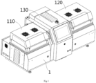
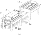
- Figure 1 shows an illustrative perspective view of a heat shrink machine according to an exemplary embodiment of the present invention.
- Figure 2 shows an illustrative perspective view of the body 1 of a heat shrink machine according to an exemplary embodiment of the present invention.
- Figure 3 shows an illustrative perspective view of a heat shrink machine according to an exemplary embodiment of the present invention, wherein the first upper safety cover 110 on the first support platform 11 is opened, and the second upper safety cover 120 on the second support platform 12 is closed.
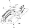
- Figure 4 shows an illustrative perspective view of the heating device of a heat shrink machine according to an exemplary embodiment of the present invention.
- the heat shrink machine mainly comprises: a body 1, multiple cable clamps 40, and a heating device.
- the machine body 1 includes a containment chamber 13 located at the standby station and a support platform 11, 12 located at the heating station.
- Multiple cable clamps 40 are installed on the support platform 11, 12 to clamp multiple cables with heat shrink tubes (not shown).
- the heating device is installed on the body 1 to heat the heat shrink tubes on the clamped cables, so that the heat shrink tubes are shrined onto the cables.
- the heating device mainly comprises a motion mechanism 2 and a heating unit 3.
- Motion mechanism 2 is used to drive the heating unit 3 to move between the standby station and the heating station, and to drive the heating unit 3 to switch between a standby orientation and a heating orientation.
- Figure 11 shows an illustrative view of a heat shrink machine according to an exemplary embodiment of the present invention, wherein the heating unit 3 is located on the first support platform 11;
- Figure 12 shows an illustrative view of a heating device of a heat shrink machine according to an exemplary embodiment of the present invention, wherein the heating unit 3 is located at the first heating station and in the first heating orientation;
- Figure 13 shows an illustrative view of a heating device of a heat shrink machine according to an exemplary embodiment of the present invention, wherein the heating unit 3 is located at the second heating station and in the second heating orientation.
- the heating unit 3 when the heating unit 3 is moved to the standby station, the heating unit 3 is located in the containment chamber 13 and in the standby orientation. When the heating unit 3 is moved to the heating station, it is located on the support platform 11, 12 and in the heating orientation.
- the support platform 11, 12 includes a first support platform 11 and a second support platform 12 located at the first heating station and the second heating station, respectively.
- the first support platform 11 and the second support platform 12 are arranged side by side and are respectively located on the left and right sides of the containment chamber 13.
- the motion mechanism 2 is used to drive the heating unit 3 to move between the standby station, the first heating station, and the second heating station, and to drive the heating unit 3 to switch between the standby orientation, the first heating orientation, and the second heating orientation.
- the heating unit 3 when the heating unit 3 is moved to the first heating station, the heating unit 3 is located on the first support platform 11 and in the first heating orientation.
- the heating unit 3 when the heating unit 3 is moved to the second heating station, the heating unit 3 is located on the second support platform 12 and in the second heating orientation.
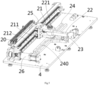
- Figure 5 shows an illustrative perspective view of the motion mechanism 2 of a heat shrink machine according to an exemplary embodiment of the present invention when viewed from one side
- Figure 6 shows an illustrative perspective view of the motion mechanism 2 of a heat shrink machine according to an exemplary embodiment of the present invention when viewed from the other side
- Figure 7 shows an illustrative perspective view of the slot rail 24 of the motion mechanism 2 according to an exemplary embodiment of the present invention.
- a motion mechanism 2 which mainly comprises a first connecting rod 21, a second connecting rod 22, a guide pin 23, and a slot rail 24.
- the first connecting rod 21 can move in a straight line in the first direction Y.
- the second connecting rod 22 is rotationally connected to the first connecting rod 21 to be able to rotate relative to the first connecting rod 21 around a pivot axis perpendicular to the first direction Y.
- the second connecting rod 22 is rotatably connected to the first connecting rod 21 through a pivot 221.
- Guide pin 23 is fixed to the second connecting rod 22.
- the slot rail 24 is formed with a guide slot 240 that fits with the guide pin 23, used to guide the guide pin 23 to move along the guide slot 240.
- the second connecting rod 22 drives the connected operating unit (such as the heating unit 3 in the illustrated embodiment) to move between different workstations and switch between different orientations, so that the driven operating unit has different orientations at different workstations.
- the connected operating unit such as the heating unit 3 in the illustrated embodiment
- the guide slot 240 is in a herringbone shape.
- the guide slot 240 includes: a first slot 241, extending along the first direction Y; a second slot 242 which is in the same straight line as the first slot 241 and is separated from the first slot 241 in the first direction Y; a third slot 243 which extends along the second direction X perpendicular to the first direction Y and the pivot axis; a first transition slot 244 which is located between one end of the first slot 241 and one end of the third slot 243; and a second transition slot 245 which is located between one end of the second slot 242 and one end of the third slot 243.
- the operating unit connected to the second connecting rod 22 is moved to the first operating station (e.g., the first heating station in the illustrated embodiment) and converted to the first operating orientation (e.g., the first heating orientation in the illustrated embodiment).
- the first operating station e.g., the first heating station in the illustrated embodiment
- the first operating orientation e.g., the first heating orientation in the illustrated embodiment
- the operating unit connected to the second connecting rod 22 is moved to the second operating station (e.g., the second heating station in the illustrated embodiment) and converted to the second operating orientation (e.g., the second heating orientation in the illustrated embodiment).
- the second operating station e.g., the second heating station in the illustrated embodiment
- the second operating orientation e.g., the second heating orientation in the illustrated embodiment
- the first slot 241 and the second slot 242 extend in a first straight line parallel to the first direction Y, and the pivot axis intersects with the first straight line.
- the operating unit in the standby orientation is converted to the first operating orientation after rotating 90 degrees in one direction around the pivot axis of the second connecting rod 22.
- the operating unit in the standby orientation is converted to the second operating orientation after rotating 90 degrees in the opposite direction around the pivot axis of the second connecting rod 22.
- the motion mechanism 2 further comprises: a guide rail 212 extending in a straight line in the first direction Y; and a slider 211 installed on the guide rail 212 in a sliding manner.
- the slider 211 is fixedly connected to the first connecting rod 21, so that the first connecting rod 21 can be driven to move in a straight line in the first direction Y by driving the slider 211.
- the motion mechanism 2 further includes a driving device for driving the slider 211 to move in a straight line along the guide rail 212.
- the aforementioned driving device comprises: a bracket 20; a pair of pulleys 261 and 262 are installed on the bracket 20 in a rotating manner; a drive belt 263, connected between the pair of pulleys 261 and 262; a motor 26, fixed to bracket 20 and its output shaft connected to a pulley 261; and a connection piece 25 is fixed to the drive belt 263 and the slider 211.
- the guide rail 212 is fixed to the bracket 20.
- the motion mechanism 2 further comprises an installation plate 200.
- the slot rail 24, guide rail 212, and bracket 20 are fixed to the installation plate 200.
- the installation plate 200 is fixed to the body 1 of the heat shrink machine and forms the bottom seat of the heat shrink machine.
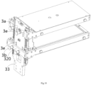
- Figure 8 shows an illustrative perspective view of the heating unit 3 of a heat shrink machine according to an exemplary embodiment of the present invention when viewed from one side
- Figure 9 shows an illustrative perspective view of the heating unit 3 of a heat shrink machine according to an exemplary embodiment of the present invention when viewed from the other side
- Figure 10 shows an illustrative perspective view of the heating unit 3 of a heat shrink machine according to an exemplary embodiment of the present invention, with the first crossbeam 310 removed.
- a heating device is also disclosed.
- the heating device mainly includes: a heating unit 3 and the aforementioned motion mechanism 2.
- Heating unit 3 is used to heat the heat shrink tube on the cable.
- the second connecting rod 22 of the motion mechanism 2 is fixedly connected to the heating unit 3, which is used to drive the heating unit 3 to move between different workstations and switch between different orientations, so that the orientations of the heating unit 3 are different at different workstations.
- the heating unit 3 comprises a pair of plate shaped heater 31, 32, and a base plate 33.
- the base plate 33 is fixedly connected to the second connecting rod 22 of the motion mechanism 2 and extends in the third direction Z parallel to the pivot axis of the second connecting rod 22.
- a pair of plate shaped heater 31 and 32 are installed on the base plate 33 and perpendicular to the third direction Z. At least one of the pair of plate shaped heaters 31 and 32 can move along the third direction Z, so that the spacing between the pair of plate shaped heaters 31 and 32 can be adjusted to match the diameter of the cable.
- the heating unit 3 further comprises: a guide rail 331 extending in straight line along a third direction Z; a first slider 311 is slidably installed on the guide rail 331; a second slider 321 is slidably installed on the guide rail 331.
- One of the pair of plate shaped heaters 31 and 32 is fixedly connected to the first slider 311, and the other is fixedly connected to the second slider 321.
- the heating unit 3 also includes: a first crossbeam 310, a second crossbeam 320, a first locking pin 3a, and a second locking pin 3b.
- the first crossbeam 310 is fixedly connected to one end of one plate shaped heater 31 and the first slider 311.
- a first through-hole 3c is formed in the first crossbeam 310.
- the second crossbeam 320 is fixedly connected to one end of the other plate-shaped heater 32 and the second slider 321, and a second through-hole 3d is formed in the second crossbeam 320.
- the first locking pin 3a is inserted into the first through-hole 3c and the corresponding locking hole 3e, to fix one plate shaped heater 31 in the first position.
- the second locking pin 3b is inserted into the second through-hole 3d and the corresponding locking hole 3e to fix the other plate-shaped heater 32 in the second position.
- the heating unit 3 may include: a first lifting device (not shown) and a second lifting device (not shown).
- the first lifting device is installed on the base plate 33 and connected to the first slider 311, which is used to drive the first slider 311 to move along the guide rail 331.
- the first lifting device may include: a first motor fixed to the base plate 33; and a first transmission mechanism connected between the output shaft of the first motor and the first slider 311.
- the second lifting device is installed on the base plate 33 and connected to the second slider 321, for driving the second slider 321 to move along the guide rail 331.
- the second lifting device may include: a second motor fixed to the base plate 33; and a second transmission mechanism connected between the output shaft of the second motor and the second slider 321.
- the heating unit 3 may include a driving motor and a threaded rod.
- the drive motor is installed on the base plate 33 and connected to the threaded rod to drive the threaded rod to rotate.
- the upper and lower parts of the threaded rod are respectively formed with a first thread and a second thread, and the thread directions of the first thread and the second thread are opposite and connected to the threads of the first slider 311 and the second slider 321, respectively.
- the driving motor rotates, the threaded rod drives the pair of plate shaped heater 31 and 32 to move towards or away from each other to adjust the spacing between them.
- the heating unit 3 in the standby orientation is converted to the first heating orientation after rotating 90 degrees to the left around the pivot axis of the second connecting rod 22.
- the heating unit 3 in the standby orientation is converted to the second heating orientation after rotating 90 degrees to the right around the pivot axis of the second connecting rod 22.
- a row of cable clamps 40 are arranged on the top surface of at least one side of the front, rear, and left sides of the first support platform 11.
- a row of cable clamps 40 is arranged on the top surface of at least one side of the front, rear, and right sides of the second support platform 12.
- the cable when the heating unit 3 is moved to the first support platform 11, the cable can enter a heating region between the pair of plate shaped heater 31 and 32 of the heating unit 3 from either side of the front, rear, or left of the first support platform 11. In this way, the application range of heat shrink machines can be expanded.
- the cable can enter a heating region between the pair of plate shaped heater 31 and 32 of the heating unit 3 from either side of the front, rear, and right sides of the second support platform 12. In this way, the application range of heat shrink machines can be expanded.
- openings 131 are formed on the left and right walls of the containment chamber 13, respectively, to allow heating unit 3 to enter and exit the containment chamber 13.
- Safety doors 132 capable of opening and closing the openings 131 are installed on the left and right walls of accommodating room 13, respectively.
- the heat shrink machine further comprises: a first upper safety cover 110, a second upper safety cover 120, and a third safety cover 130.
- the first safety cover 110 is rotatably connected to the left wall of the containment chamber 13 and can be rotated to open and close.
- the second upper safety cover 120 is rotatably connected to the right wall of the containment chamber 13 and can be rotated to open and close.
- the first upper safety cover 110 closes to cover the heating unit 3, cable clamps 40, and the heat shrink tubes on the cables located on the first support platform 11, and the second upper safety cover 120 opens to allow the cables to be clamped on the second support platform 12.
- the second upper safety cover 120 closes to cover the heating unit 3, cable clamps 40, and the heat shrink tubes on the cables located on the second support platform 12, and the first upper safety cover 110 opens to allow the cables to be clamped on the first support platform 11.
- the third safety cover 130 is installed on the top opening of the containment chamber 13 and can be opened and closed.
- Figure 14 shows a sectional view of a heat shrink machine according to an exemplary embodiment of the present invention, wherein the heating unit 3 is located at the heating station;
- Figure 15 shows a partially enlarged schematic diagram of the heat shrink machine shown in Figure 14 , which shows the heating unit 3, heat reflection plates 34, 34', 35, and safety covers 110, 120, 110', 120';
- Figure 16 shows an illustrative perspective view of the heating unit 3 of a heat shrink machine according to an exemplary embodiment of the present invention;
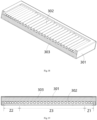
- Figure 17 shows an illustrative perspective view of a plate shaped heater 31 and 32 according to an exemplary embodiment of the present invention;
- Figure 18 shows a longitudinal sectional view of the plate shaped heater 31 and 32 according to an exemplary embodiment of the present invention;
- Figure 19 shows a vertical sectional view of the plate shaped heater 31 and 32 according to an exemplary embodiment of the present invention;
- Figure 20 shows a cross-sectional view along the horizontal direction of the plate shaped heater 31 and 32 according to an exemplary embodiment of the
- a plate shaped heater 31 and 32 is disclosed.
- the plate shaped heater 31 and 32 is used to heat the heat shrink tubes on the cables.
- the plate shaped heater 31 and 32 includes: a housing 301, multiple heating tubes 302, and a heating wire 304.
- the housing 301 has opposite ends in its longitudinal direction Y'. Multiple heating tubes 302 are installed in the housing 301.
- the heating wire 304 is arranged in multiple heating tubes 302.
- the heating wire 304 can be a single heating wire that passes through multiple heating tubes 302 in sequence, or multiple heating wires that are inserted into multiple heating tubes 302 separately.
- the heating tube 302 extends along the horizontal direction X' of the housing 301, and multiple heating tubes 302 are arranged in a row along the longitudinal direction Y' of the housing 301.
- the arrangement density of heating tubes 302 in the two end regions Z1 and Z2 near the housing 301 is higher than that in the middle region Z3 between the two end regions Z1 and Z2 of the housing 301. That is to say, the arrangement density of heating tubes 302 in the end region of the plate shaped heater 31 and 32 is higher than that in the middle region of the plate shaped heater 31 and 32. This makes the heating temperature in the end region of the plate shaped heater 31 and 32 basically consistent with the heating temperature in the middle region of the plate shaped heater 31 and 32, thereby improving the heating uniformity of the plate shaped heater 31 and 32.
- the length of the heating wire 304 set in the heating tube 302 in the end regions Z1 and Z2 is greater than the length of the heating wire 304 set in the heating tube 302 in the middle region Z3. This can further improve the heating uniformity of the plate shaped heater 31 and 32.
- the heating region of multiple heating tubes 302 can cover all cable clamps 40, so that the heat shrink tubes of all cables clamped on the cable clamps 40 can be uniformly heated by the plate shaped heater 31 and 32.
- one end of the housing 301 is used to connect to the base plate 33.
- the aforementioned two end regions Z1 and Z2 include a first end region Z1 near one end of the housing 301 and a second end region Z2 near the other end of the housing 301.
- the heat shrink tubes located in the first end region Z1 first enters the heating region between the pair of plate shaped heaters 31 and 32, and then the heat shrink tubes located in the second end region Z2 enters the heating region between the pair of plate shaped heaters 31 and 32. This results in the heating time of the heat shrink tubes located in the second end region Z2 being shorter than the heating time of the heat shrink tubes located in the first end region Z1.
- the arrangement density of the heating tube 302 in the first end region Z1 is lower than that of the heating tube 302 in the second end region Z2.
- the present invention is not limited to the illustrated embodiments.
- the arrangement density of the heating tubes 302 in the first end region Z1 can also be set to be equal to the arrangement density of the heating tubes 302 in the second end region Z2.
- the length of the heating wire 304 set in the heating tube 302 in the first end region Z1 is smaller than the length of the heating wire 304 set in the heating tube 302 in the second end region Z2.
- the present invention is not limited to the illustrated embodiments.
- the length of the heating wire 304 in the heating tube 302 in the first end region Z1 can also be set to be equal to the length of the heating wire 304 in the heating tube 302 in the second end region Z2.
- the plate shaped heater 31 and 32 further includes: an adiabatic sponge 303 and a panel 305.
- the adiabatic sponge 303 is set between the housing 301 and the heating tube 302 to prevent heat from being transferred from the heating tube 302 to the housing 301.
- the panel 305 is installed on the opening of housing 301, and there is no adiabatic sponge 303 set between the panel 305 and the heating tube 302. The heat generated by the plate shaped heaters 31 and 32 radiates outward from the panel 305 to heat the heat shrink tubes on the cables facing the panel 305.
- a heating unit 3 is also disclosed.
- the heating unit 3 includes a base plate 33 and a pair of plate shaped heaters 31 and 32. One ends of the pair of plate shaped heaters 31 and 32 are connected to the base plate 33.
- the pair of plate shaped heaters 31 and 32 are spaced opposite and parallel to each other in the height direction perpendicular to their longitudinal direction Y' and transverse direction X', used to heat the heat shrink tubes on the cables between the pair of plate shaped heaters 31 and 32.
- At least one of the pair of plate shaped heaters 31 and 32 can move in the height direction Z' relative to the base plate 33, so that the spacing between the pair of plate-shaped heaters 31 and 32 can be adjusted to match the diameter of the cable.
- the heating unit 3 further includes: a guide rail 331, a first slider 311, and a second slider 321.
- the guide rail 331 extends in a straight line along the height direction and is fixed to the base plate 33.
- the first slider 311 is slidably installed on the guide rail 331.
- the second slider 321 is slidably installed on the guide rail 331.
- One of the pair of plate shaped heaters 31 and 32 is fixedly connected to the first slider 311, and the other is fixedly connected to the second slider 321, allowing the pair of plate shaped heaters 31 and 32 to move along the guide rail 331 respectively.
- the heating unit 3 further comprises a first heat reflection plate 35.
- the first heat reflection plate 35 is provided on the opening at one ends of the pair of plate-shaped heaters 31 and 32 and is fixed to the base plate 33.
- the first heat reflection plate 35 is used to reflect heat into the heating region between the pair of plate shaped heater 31 and 32, in order to prevent heat from flowing from the opening at one ends of the pair of plate shaped heaters 31 and 32 to the outside of the heating region. This can improve heating efficiency and uniformity.
- a heat shrink machine is also disclosed.
- the heat shrink machine includes: a body 1, cable clamps 40, a heating unit 3, and a motion mechanism 2.
- the machine body 1 includes a containment chamber 13 located at the standby station and a support platform 11, 12 located at the heating station. Cable clamps 40 are installed on the support platform 11, 12 to clamp cables with heat shrink tubes.
- the heating unit 3 is used to heat the heat shrink tubes on the cables.
- the motion mechanism 2 is connected to the base plate 33 of the heating unit 3, which is used to drive the heating unit 3 to move between the standby station and the heating station, and to switch between the standby orientation and the heating orientation.
- the heating unit 3 when the heating unit 3 is moved to the standby station, the heating unit 3 is located in the containment chamber 13 and in the standby orientation; When heating unit 3 is moved to the heating station, it is located on support platform 11, 12 and in the heating orientation.
- the motion mechanism 2 comprises: a first connecting rod 21, a second connecting rod 22, a guide pin 23, and a slot rail 24.
- the first connecting rod 21 is connected to a driving mechanism and can move accordingly.
- the second connecting rod 22 is pivotally connected to the first connecting rod 21 to rotate around a pivot axis relative to the first connecting rod 21.
- the guide pin 23 is fixed to the second connecting rod 22.
- the slot rail 24 is formed with a guide slot 240 that slidably fits with the guide pin 23, used to guide the guide pin 23 to move along the guide slot 240.
- the end of the second connecting rod 22 is fixedly connected to the base plate 33 of the heating unit 3.
- the pair of plate shaped heaters 31 and 32 have a first end connected to the base plate 33 and a second end opposite to the first end.
- the cable clamp 40 enters between the pair of plate shaped heaters 31 and 32 through the opening between the second ends of the pair of plate shaped heaters 31 and 32.
- the heating unit 3 comprises a first heat reflection plate 35.
- the first heat reflection plate 35 is provided on the opening at the first ends of the pair of plate shaped heaters 31 and 32.
- the first heat reflection plate 35 is used to reflect heat into the heating region between the pair of plate shaped heaters 31 and 32, in order to prevent heat from flowing from the opening at the first ends of the pair of plate shaped heaters 31 and 32 to the outside of the heating region. This can improve heating efficiency and uniformity
- the heat shrink machine further comprises second heat reflection plates 34, 34'.
- the second heat reflection plates 34 and 34' are fixed to the support platform 11, 12 or the housing 301 of the plate shaped heater 31 and 32.
- the second heat reflection plates 34 and 34 cover the opening of the second ends of the pair of plate shaped heater 31 and 32, which is used to reflect heat into the heating region between the pair of plate shaped heater 31 and 32, to prevent heat from flowing from the opening at the second ends of the pair of plate shaped heater 31 and 32 to the outside of the heating region. This can improve heating efficiency and uniformity.
- the second heat reflection plates 34, 34' include: an upper reflection plate 34 and a lower reflection plate 34'.
- the upper reflection plate 34 is located above and fixed to the support platform 11, 12.
- the lower reflection plate 34' is located below and fixed to the support platform 11, 12.
- the heat shrink machine further comprises safety covers 110, 120, 110', and 120'.
- the safety covers 110, 120, 110', and 120' are installed on the body 1.
- the heating unit 3 is accommodated in the safety covers 110, 120, 110', 120' to isolate it from external air.
- the safety covers 110, 120, 110', 120' include: upper safety covers 110, 120, and lower safety covers 110', 120'.
- the upper safety covers 110 and 120 are located above the support platform 11, 12 and can be opened and closed.
- the lower safety covers 110'and 120' are located below and fixed to the support platform 11, 12.
- the time for heating unit 3 to move from the standby station to the heating station or from the heating station to the standby station does not exceed 1 second. This can reduce the heating time difference between the two ends of the plate shaped heater 31 and 32, thereby further improving heating uniformity.
- the structure of the heat shrink machine of the present invention is not limited to the illustrated embodiments.
- the pair of plate shaped heaters 31 and 32 in the heating unit 3 can also move from one side to the other along the lateral direction (in the second direction X in the figure) of the support platform 11, 12.
Landscapes
- Physics & Mathematics (AREA)
- Thermal Sciences (AREA)
- Engineering & Computer Science (AREA)
- Manufacturing & Machinery (AREA)
- Resistance Heating (AREA)
- Heating, Cooling, Or Curing Plastics Or The Like In General (AREA)
- Warehouses Or Storage Devices (AREA)
Abstract
Description
- This application claims the benefit of Chinese Patent Application No.
CN202310213145.9 filed on March 7, 2023 - The present invention relates to a plate shaped heater, a heating unit comprising the plate shaped heater, and a heat shrink machine comprising the heating unit.
- The heating unit of a heat shrink machine usually includes two plate shaped heaters, upper and lower. In the prior art, the heating region with uniform temperature in the heating unit is limited to the middle region of the heating unit, resulting in its two ends being unable to be used for heating the wire harness heat shrink tube, which not only reduces production efficiency but also wastes some energy consumption. In addition, in the prior art, due to structural limitations, the density of the heating wire at both ends of the heater cannot be increased, which results in the temperature at both ends of the heating unit always being lower than the middle temperature, and thus the two ends cannot be used for heating the wire harness heat shrink tube, affecting the improvement of production efficiency.
- In the prior art, the normal operating temperature of the heater of the heat shrink machine is between 500-600°C, and the temperature difference with the external environment is too large. Therefore, during heating, heat will be lost through the openings at both ends of the upper and lower heaters, resulting in lower temperatures at the two ends of the heater, which further leads to uneven heating.
- The present invention has been made to overcome or alleviate at least one aspect of the above mentioned disadvantages.
- According to an aspect of the present invention, there is provided a plate shaped heater for heating a heat shrink tube on a cable. The plate shaped heater comprises of a housing with opposite ends in its longitudinal direction; multiple heating tubes provided in the housing; and a heating wire provided in the multiple heating tubes. The heating tube extends along a transverse direction of the housing, and the multiple heating tubes are arranged in a row along the longitudinal direction of the housing. The arrangement density of the heating tubes in two end regions near two ends of the housing is greater than the arrangement density of the heating tubes in a middle region between the two end regions of the housing.
- According to an exemplary embodiment of the present invention, the length of the heating wire set in the heating tube in the end region is greater than the length of the heating wire set in the heating tube in the middle region.
- According to another exemplary embodiment of the present invention, the heating region of the multiple heating tubes covers all cable clamps, so that the heat shrink tubes of all cables clamped on the cable clamps are uniformly heated by the plate shaped heater.
- According to another exemplary embodiment of the present invention, one end of the housing is used to connect to a base plate, and the two end regions include a first end region near one end of the housing and a second end region near the other end of the housing; the arrangement density of the heating tubes in the first end region is less than or equal to the arrangement density of the heating tubes in the second end region.
- According to another exemplary embodiment of the present invention, the length of the heating wire set in the heating tube in the first end region is less than or equal to the length of the heating wire set in the heating tube in the second end region.
- According to another exemplary embodiment of the present invention, The plate shaped heater further comprises of an adiabatic sponge provided between the housing and the heating tube to prevent heat from being transferred from the heating tube to the housing; and a panel installed on an opening of the housing. There is no adiabatic sponge provided between the panel and the heating tube, the heat generated by the plate shaped heater radiates outward from the panel to heat the heat shrink tube on the cable.
- According to another aspect of the present invention, there is provided a heating unit. The heating unit comprises of a base plate; and a pair of plate shaped heaters, one ends of which are connected to the base plate. The pair of plate shaped heaters are spaced opposite and parallel to each other in a height direction perpendicular to a longitudinal direction and a transverse direction of the plate shaped heater, for heating the heat shrink tubes on cables located between the pair of plate shaped heater.
- According to an exemplary embodiment of the present invention, at least one of the pair of plate shaped heaters is movable relative to the base plate along the height direction, so that the spacing between the pair of plate shaped heaters is capable of being adjusted to match the diameter of the cable.
- According to another exemplary embodiment of the present invention, the heating unit further comprises of a guide rail that extends in a straight line along the height direction and is fixed to the base plate; a first slider which is slidably installed on the guide rail; and a second slider which is slidably installed on the guide rail. One of the pair of plate shaped heaters is fixedly connected to the first slider, and the other is fixedly connected to the second slider, so that the pair of plate shaped heaters are movable along the guide rail.
- According to another exemplary embodiment of the present invention, the heating unit further comprises a first heat reflection plate which is provided at an opening at one ends of the pair of plate shaped heaters and fixed to the base plate, the first heat reflection plate is used to reflect heat into the heating region between the pair of plate shaped heaters to prevent heat from flowing from the opening at one ends of the pair of plate shaped heaters to the outside of the heating region.
- According to another aspect of the present invention, there is provided a heat shrink machine. The heat shrink machine comprises of a body includes a containment chamber located at a standby station and a support platform located at a heating station; cable clamps installed on the support platform for clamping cables with heat shrink tubes; the above heating unit, for heating the heat shrink tubes on the cables; and a motion mechanism which is connected to the base plate of the heating unit, for driving the heating unit to move between the standby station and the heating station, and to switch between a standby orientation and a heating orientation. When the heating unit is moved to the standby station, the heating unit is located in the containment chamber and in the standby orientation; when the heating unit is moved to the heating station, the heating unit is located on the support platform and in the heating orientation.
- According to an exemplary embodiment of the present invention, the motion mechanism comprises of a first connecting rod which is connected to a driving mechanism to move with the driving mechanism; a second connecting rod which is pivotally connected to the first connecting rod to rotate about a pivot axis relative to the first connecting rod; a guide pin fixed to the second connecting rod; and a slot rail formed with a guide slot that slidably fits with the guide pin, used to guide the guide pin to move along the guide slot. An end of the second connecting rod is fixedly connected to the base plate of the heating unit.
- According to another exemplary embodiment of the present invention, the plate shaped heater has a first end connected to the base plate and a second end opposite to the first end; during the movement of the heating unit from the standby station to the heating station, the cable clamp enters into a heating region between the pair of plate shaped heaters through an opening at the second ends of the pair of plate shaped heaters.
- According to another exemplary embodiment of the present invention, the heating unit comprises a first heat reflection plate which is provided on an opening at the first ends of the pair of plate shaped heaters, the first heat reflection plate is used to reflect heat into the heating region between the pair of plate shaped heaters to prevent heat from flowing from the opening at the first ends of the pair of plate shaped heaters to the outside of the heating region.
- According to another exemplary embodiment of the present invention, the heat shrink machine further comprises a second heat reflection plate which is fixed to the support platform or the housing of the plate-shaped heater. When the heating unit is moved to the heating station, the second heat reflection plate covers the opening at the second ends of the pair of plate shaped heaters, used to reflect heat into the heating region between the pair of plate shaped heaters, to prevent heat from flowing from the opening at the second ends of the pair of plate shaped heaters to the outside of the heating region.
- According to another exemplary embodiment of the present invention, the second heat reflection plate comprises of an upper reflection plate which is located above the support platform and fixed to the support platform; and a lower reflection plate which is located below the support platform and fixed to the support platform.
- According to another exemplary embodiment of the present invention, the heat shrink machine further comprises a safety cover installed on the body. When heating the heat shrink tubes on the cables, the heating unit is accommodated in the safety cover to isolate the heating unit from external air.
- According to another exemplary embodiment of the present invention, the safety cover comprises of an upper safety cover which is located above the support platform and is capable of being opened and closed; and a lower safety cover which is located below the support platform and fixed to the support platform.
- According to another exemplary embodiment of the present invention, the time for the heating unit to move from the standby station to the heating station or from the heating station to the standby station shall not exceed 1 second.
- In the aforementioned exemplary embodiments of the present invention, the arrangement density of the heating tubes in the end region of the plate shaped heater is greater than that in the middle region of the plate shaped heater, which makes the heating temperature in the end region of the plate shaped heater basically consistent with the heating temperature in the middle region of the plate shaped heater, thereby improving the heating uniformity of the plate shaped heater.
- The above and other features of the present invention will become more apparent by describing in detail exemplary embodiments thereof with reference to the accompanying drawings, in which:
-
Figure 1 shows an illustrative perspective view of a heat shrink machine according to an exemplary embodiment of the present invention; -
Figure 2 shows an illustrative perspective view of a body of a heat shrink machine according to an exemplary embodiment of the present invention; -
Figure 3 shows an illustrative perspective view of a heat shrink machine according to an exemplary embodiment of the present invention, wherein the first upper safety cover on the first support platform is opened, and the second upper safety cover on the second support platform is closed; -
Figure 4 shows an illustrative perspective view of a heating device of a heat shrink machine according to an exemplary embodiment of the present invention; -
Figure 5 shows an illustrative perspective view of a motion mechanism of a heat shrink machine according to an exemplary embodiment of the present invention when viewed from one side; -
Figure 6 shows an illustrative perspective view of a motion mechanism of a heat shrink machine according to an exemplary embodiment of the present invention when viewed from the other side; -
Figure 7 shows an illustrative perspective view of a slot rail of a motion mechanism according to an exemplary embodiment of the present invention; -
Figure 8 shows an illustrative perspective view of a heating device of a heat shrink machine according to an exemplary embodiment of the present invention when viewed from one side; -
Figure 9 shows an illustrative perspective view of a heating device of a heat shrink machine according to an exemplary embodiment of the present invention when viewed from the other side; -
Figure 10 shows an illustrative perspective view of a heating device of a heat shrink machine according to an exemplary embodiment of the present invention, wherein thefirst crossbeam 310 is removed; -
Figure 11 shows an illustrative view of a heat shrink machine according to an exemplary embodiment of the present invention, wherein the heating device is located on a first support platform; -
Figure 12 shows an illustrative view of a heating device of a heat shrink machine according to an exemplary embodiment of the present invention, wherein the heating device is located at the first heating station and in the first heating orientation; -
Figure 13 shows an illustrative view of a heating device of a heat shrink machine according to an exemplary embodiment of the present invention, wherein the heating device is located at a second heating station and in a second heating orientation; -
Figure 14 shows a sectional view of a heat shrink machine according to an exemplary embodiment of the present invention, wherein the heating unit is located at the heating station; -
Figure 15 shows a partially enlarged schematic diagram of the heat shrink machine shown inFigure 14 , which shows the heating unit, heat reflection plate, and safety cover; -
Figure 16 shows an illustrative perspective view of a heating unit of a heat shrink machine according to an exemplary embodiment of the present invention; -
Figure 17 shows an illustrative perspective view of a plate shaped heater according to an exemplary embodiment of the present invention; -
Figure 18 shows a longitudinal sectional view of a plate shaped heater according to an exemplary embodiment of the present invention; -
Figure 19 shows a vertical cross-sectional view of a plate shaped heater according to an exemplary embodiment of the present invention; -
Figure 20 shows a cross-sectional view along the horizontal direction of a plate shaped heater according to an exemplary embodiment of the present invention; and -
Figure 21 shows a schematic arrangement diagram of a heating unit and a heat reflection plate according to an exemplary embodiment of the present invention. - Exemplary embodiments of the present disclosure will be described hereinafter in detail with reference to the attached drawings, wherein the like reference numerals refer to the like elements. The present disclosure may, however, be embodied in many different forms and should not be construed as being limited to the embodiment set forth herein; rather, these embodiments are provided so that the present disclosure will be thorough and complete, and will fully convey the concept of the disclosure to those skilled in the art.
- In the following detailed description, for purposes of explanation, numerous specific details are set forth in order to provide a thorough understanding of the disclosed embodiments. It will be apparent, however, that one or more embodiments may be practiced without these specific details. In other instances, well-known structures and devices are schematically shown in order to simplify the drawing.
- According to a general concept of the present invention, there is provided a plate shaped heater for heating a heat shrink tube on a cable. The plate shaped heater comprises of a housing with opposite ends in its longitudinal direction; multiple heating tubes provided in the housing; and a heating wire provided in the multiple heating tubes. The heating tube extends along a transverse direction of the housing, and the multiple heating tubes are arranged in a row along the longitudinal direction of the housing. The arrangement density of the heating tubes in two end regions near two ends of the housing is greater than the arrangement density of the heating tubes in a middle region between the two end regions of the housing.
- According to another general concept of the present invention, there is provided a heating unit. The heating unit comprises of a base plate; and a pair of plate shaped heaters, one ends of which are connected to the base plate. The pair of plate shaped heaters are spaced opposite and parallel to each other in a height direction perpendicular to a longitudinal direction and a transverse direction of the plate shaped heater, for heating the heat shrink tubes on cables located between the pair of plate shaped heater.
- According to another general concept of the present invention, there is provided a heat shrink machine. The heat shrink machine comprises of a body includes a containment chamber located at a standby station and a support platform located at a heating station; cable clamps installed on the support platform for clamping cables with heat shrink tubes; the above heating unit, for heating the heat shrink tubes on the cables; and a motion mechanism which is connected to the base plate of the heating unit, for driving the heating unit to move between the standby station and the heating station, and to switch between a standby orientation and a heating orientation. When the heating unit is moved to the standby station, the heating unit is located in the containment chamber and in the standby orientation; when the heating unit is moved to the heating station, the heating unit is located on the support platform and in the heating orientation.
- According to another general concept of the present invention, there is provided a motion mechanism. The motion mechanism comprises of a first connecting rod connected to a driving mechanism to move with it; a second connecting rod which is pivotally connected to the first connecting rod to rotate around a pivot axis relative to the first connecting rod; a guide pin fixed to the second connecting rod; a slot rail formed with a guide slot which is slidably mated with the guide pin to guide the guide pin to move along the guide slot. When the first connecting rod is driven to move, the second connecting rod drives an operating unit connected to it to switch between different orientations, so that the driven operating unit has different orientations.
- According to another general concept of the present invention, there is provided a heating device. The heating device comprises of a heating unit for heating; the above motion mechanism, second connecting rod of which is fixedly connected to the heating unit to drive the heating unit to switch between different orientations, so that the heating unit has different orientations.
- According to another general concept of the present invention, a heat shrink machine is provided. The heat shrink machine comprises of: a body comprising a containment chamber located at a standby station and a support platform located at a heating station; cable clamps installed on the support platform for clamping cables with heat shrink tubes; and the above heating device installed on the body to heat the heat shrink tubes on the clamped cables. The motion mechanism is used to drive the heating unit to move between the standby station and the heating station and to switch between the standby orientation and the heating orientation. When the heating unit is moved to the standby station, the heating unit is located in the containment chamber and in the standby orientation; When the heating unit is moved to the heating station, the heating unit is located on the support platform and in the heating orientation.
- According to another overall technical concept of the present invention, a motion mechanism is provided. The motion mechanism comprises of a first connecting
rod 21 connected to a driving mechanism to move with it; a second connectingrod 22 which is pivotally connected to the first connectingrod 21 to rotate about a pivot axis relative to the first connectingrod 21; aguide pin 23 fixed to the second connectingrod 22; aslot rail 24 formed with aguide slot 240 which is slidably fitted with theguide pin 23 to guide theguide pin 23 to move along theguide slot 240. When the first connectingrod 21 is driven to move, the second connectingrod 22 drives an operating unit connected to it to move between different workstations and switch between different orientations, so that the driven operating unit has different orientations at different workstations. -
Figure 1 shows an illustrative perspective view of a heat shrink machine according to an exemplary embodiment of the present invention.Figure 2 shows an illustrative perspective view of thebody 1 of a heat shrink machine according to an exemplary embodiment of the present invention.Figure 3 shows an illustrative perspective view of a heat shrink machine according to an exemplary embodiment of the present invention, wherein the firstupper safety cover 110 on thefirst support platform 11 is opened, and the secondupper safety cover 120 on thesecond support platform 12 is closed.Figure 4 shows an illustrative perspective view of the heating device of a heat shrink machine according to an exemplary embodiment of the present invention. - As shown in
Figures 1 to 4 , in the illustrated embodiments, the heat shrink machine mainly comprises: abody 1, multiple cable clamps 40, and a heating device. Themachine body 1 includes acontainment chamber 13 located at the standby station and asupport platform support platform body 1 to heat the heat shrink tubes on the clamped cables, so that the heat shrink tubes are shrined onto the cables. - As shown in
Figures 1 to 4 , in the illustrated embodiments, the heating device mainly comprises amotion mechanism 2 and aheating unit 3.Motion mechanism 2 is used to drive theheating unit 3 to move between the standby station and the heating station, and to drive theheating unit 3 to switch between a standby orientation and a heating orientation. -
Figure 11 shows an illustrative view of a heat shrink machine according to an exemplary embodiment of the present invention, wherein theheating unit 3 is located on thefirst support platform 11;Figure 12 shows an illustrative view of a heating device of a heat shrink machine according to an exemplary embodiment of the present invention, wherein theheating unit 3 is located at the first heating station and in the first heating orientation;Figure 13 shows an illustrative view of a heating device of a heat shrink machine according to an exemplary embodiment of the present invention, wherein theheating unit 3 is located at the second heating station and in the second heating orientation. - As shown in
Figures 1-4 to 11-13 , in the illustrated embodiment, when theheating unit 3 is moved to the standby station, theheating unit 3 is located in thecontainment chamber 13 and in the standby orientation. When theheating unit 3 is moved to the heating station, it is located on thesupport platform - As shown in
Figures 1-4 to 11-13 , in the illustrated embodiments, thesupport platform first support platform 11 and asecond support platform 12 located at the first heating station and the second heating station, respectively. Thefirst support platform 11 and thesecond support platform 12 are arranged side by side and are respectively located on the left and right sides of thecontainment chamber 13. - As shown in
Figures 1-4 to 11-13 , in the illustrated embodiments, themotion mechanism 2 is used to drive theheating unit 3 to move between the standby station, the first heating station, and the second heating station, and to drive theheating unit 3 to switch between the standby orientation, the first heating orientation, and the second heating orientation. - As shown in
Figures 1-4 to 11-13 , in the illustrated embodiment, when theheating unit 3 is moved to the first heating station, theheating unit 3 is located on thefirst support platform 11 and in the first heating orientation. - As shown in
Figures 1-4 to 11-13 , in the illustrated embodiment, when theheating unit 3 is moved to the second heating station, theheating unit 3 is located on thesecond support platform 12 and in the second heating orientation. -
Figure 5 shows an illustrative perspective view of themotion mechanism 2 of a heat shrink machine according to an exemplary embodiment of the present invention when viewed from one side;Figure 6 shows an illustrative perspective view of themotion mechanism 2 of a heat shrink machine according to an exemplary embodiment of the present invention when viewed from the other side;Figure 7 shows an illustrative perspective view of theslot rail 24 of themotion mechanism 2 according to an exemplary embodiment of the present invention. - As shown in
Figures 1-7 to 11-13 , in an exemplary embodiment of the present invention, there is also disclosed amotion mechanism 2, which mainly comprises a first connectingrod 21, a second connectingrod 22, aguide pin 23, and aslot rail 24. The first connectingrod 21 can move in a straight line in the first direction Y. The second connectingrod 22 is rotationally connected to the first connectingrod 21 to be able to rotate relative to the first connectingrod 21 around a pivot axis perpendicular to the first direction Y. In the illustrated embodiment, the second connectingrod 22 is rotatably connected to the first connectingrod 21 through apivot 221.Guide pin 23 is fixed to the second connectingrod 22. Theslot rail 24 is formed with aguide slot 240 that fits with theguide pin 23, used to guide theguide pin 23 to move along theguide slot 240. - As shown in
Figures 1-7 to 11-13 , in the illustrated embodiment, when the first connectingrod 21 is driven to move in a straight line in the first direction Y, the second connectingrod 22 drives the connected operating unit (such as theheating unit 3 in the illustrated embodiment) to move between different workstations and switch between different orientations, so that the driven operating unit has different orientations at different workstations. - As shown in
Figures 1-7 to 11-13 , in the illustrated embodiment, theguide slot 240 is in a herringbone shape. Theguide slot 240 includes: afirst slot 241, extending along the first direction Y; asecond slot 242 which is in the same straight line as thefirst slot 241 and is separated from thefirst slot 241 in the first direction Y; athird slot 243 which extends along the second direction X perpendicular to the first direction Y and the pivot axis; afirst transition slot 244 which is located between one end of thefirst slot 241 and one end of thethird slot 243; and asecond transition slot 245 which is located between one end of thesecond slot 242 and one end of thethird slot 243. - As shown in
Figures 1-7 to 11-13 , in the illustrated embodiment, when theguide pin 23 moves to the first predetermined position in thefirst slot 241, the operating unit connected to the second connectingrod 22 is moved to the first operating station (e.g., the first heating station in the illustrated embodiment) and converted to the first operating orientation (e.g., the first heating orientation in the illustrated embodiment). - As shown in
Figures 1-7 to 11-13 , in the illustrated embodiment, when theguide pin 23 is moved to the second predetermined position in thesecond slot 242, the operating unit connected to the second connectingrod 22 is moved to the second operating station (e.g., the second heating station in the illustrated embodiment) and converted to the second operating orientation (e.g., the second heating orientation in the illustrated embodiment). - As shown in
Figures 1-7 to 11-13 , in the illustrated embodiment, when theguide pin 23 moves to the third predetermined position in thethird slot 243, the operating unit connected to the second connectingrod 22 is moved to the standby station and converted to the standby orientation. - As shown in
Figures 1-7 to 11-13 , in the illustrated embodiment, thefirst slot 241 and thesecond slot 242 extend in a first straight line parallel to the first direction Y, and the pivot axis intersects with the first straight line. - As shown in
Figures 1-7 to 11-13 , in the illustrated embodiment, the operating unit in the standby orientation is converted to the first operating orientation after rotating 90 degrees in one direction around the pivot axis of the second connectingrod 22. - As shown in
Figures 1-7 to 11-13 , in the illustrated embodiment, the operating unit in the standby orientation is converted to the second operating orientation after rotating 90 degrees in the opposite direction around the pivot axis of the second connectingrod 22. - As shown in
Figures 1-7 to 11-13 , in the illustrated embodiment, themotion mechanism 2 further comprises: aguide rail 212 extending in a straight line in the first direction Y; and aslider 211 installed on theguide rail 212 in a sliding manner. Theslider 211 is fixedly connected to the first connectingrod 21, so that the first connectingrod 21 can be driven to move in a straight line in the first direction Y by driving theslider 211. - As shown in
Figures 1-7 to 11-13 , in the illustrated embodiment, themotion mechanism 2 further includes a driving device for driving theslider 211 to move in a straight line along theguide rail 212. - As shown in
Figures 1-7 to 11-13 , in the illustrated embodiments, the aforementioned driving device comprises: abracket 20; a pair ofpulleys bracket 20 in a rotating manner; adrive belt 263, connected between the pair ofpulleys motor 26, fixed tobracket 20 and its output shaft connected to apulley 261; and aconnection piece 25 is fixed to thedrive belt 263 and theslider 211. In the illustrated embodiment, theguide rail 212 is fixed to thebracket 20. - As shown in
Figures 1-7 to 11-13 , in the illustrated embodiment, when themotor 26 rotates, it drives thedrive belt 263 to move and drives theslider 211 to move in a straight line along theguide rail 212 through thedrive belt 263. - As shown in
Figures 1-7 to 11-13 , in the illustrated embodiment, themotion mechanism 2 further comprises aninstallation plate 200. Theslot rail 24,guide rail 212, andbracket 20 are fixed to theinstallation plate 200. In the illustrated embodiment, theinstallation plate 200 is fixed to thebody 1 of the heat shrink machine and forms the bottom seat of the heat shrink machine. -
Figure 8 shows an illustrative perspective view of theheating unit 3 of a heat shrink machine according to an exemplary embodiment of the present invention when viewed from one side;Figure 9 shows an illustrative perspective view of theheating unit 3 of a heat shrink machine according to an exemplary embodiment of the present invention when viewed from the other side;Figure 10 shows an illustrative perspective view of theheating unit 3 of a heat shrink machine according to an exemplary embodiment of the present invention, with thefirst crossbeam 310 removed. - As shown in
Figures 1 to 13 , in an exemplary embodiment of the present invention, a heating device is also disclosed. The heating device mainly includes: aheating unit 3 and theaforementioned motion mechanism 2.Heating unit 3 is used to heat the heat shrink tube on the cable. The second connectingrod 22 of themotion mechanism 2 is fixedly connected to theheating unit 3, which is used to drive theheating unit 3 to move between different workstations and switch between different orientations, so that the orientations of theheating unit 3 are different at different workstations. - As shown in
Figures 1 to 13 , in the illustrated embodiment, theheating unit 3 comprises a pair of plate shapedheater base plate 33. Thebase plate 33 is fixedly connected to the second connectingrod 22 of themotion mechanism 2 and extends in the third direction Z parallel to the pivot axis of the second connectingrod 22. A pair of plate shapedheater base plate 33 and perpendicular to the third direction Z. At least one of the pair of plate shapedheaters heaters - As shown in
Figures 1 to 13 , in the illustrated embodiment, theheating unit 3 further comprises: aguide rail 331 extending in straight line along a third direction Z; afirst slider 311 is slidably installed on theguide rail 331; asecond slider 321 is slidably installed on theguide rail 331. One of the pair of plate shapedheaters first slider 311, and the other is fixedly connected to thesecond slider 321. - As shown in
Figures 1 to 13 , in the illustrated embodiments, multiple locking holes 3e spaced apart from each other in the third direction Z are formed on thebase plate 33. Theheating unit 3 also includes: afirst crossbeam 310, asecond crossbeam 320, afirst locking pin 3a, and asecond locking pin 3b. Thefirst crossbeam 310 is fixedly connected to one end of one plate shapedheater 31 and thefirst slider 311. A first through-hole 3c is formed in thefirst crossbeam 310. Thesecond crossbeam 320 is fixedly connected to one end of the other plate-shapedheater 32 and thesecond slider 321, and a second through-hole 3d is formed in thesecond crossbeam 320. Thefirst locking pin 3a is inserted into the first through-hole 3c and the corresponding locking hole 3e, to fix one plate shapedheater 31 in the first position. Thesecond locking pin 3b is inserted into the second through-hole 3d and the corresponding locking hole 3e to fix the other plate-shapedheater 32 in the second position. - Please note that the present invention is not limited to the illustrated embodiments. For example, in another exemplary embodiment of the present invention, the
heating unit 3 may include: a first lifting device (not shown) and a second lifting device (not shown). The first lifting device is installed on thebase plate 33 and connected to thefirst slider 311, which is used to drive thefirst slider 311 to move along theguide rail 331. For example, the first lifting device may include: a first motor fixed to thebase plate 33; and a first transmission mechanism connected between the output shaft of the first motor and thefirst slider 311. The second lifting device is installed on thebase plate 33 and connected to thesecond slider 321, for driving thesecond slider 321 to move along theguide rail 331. For example, the second lifting device may include: a second motor fixed to thebase plate 33; and a second transmission mechanism connected between the output shaft of the second motor and thesecond slider 321. - Please note that the present invention is not limited to the illustrated embodiments. For example, in another exemplary embodiment of the present invention, the
heating unit 3 may include a driving motor and a threaded rod. The drive motor is installed on thebase plate 33 and connected to the threaded rod to drive the threaded rod to rotate. The upper and lower parts of the threaded rod are respectively formed with a first thread and a second thread, and the thread directions of the first thread and the second thread are opposite and connected to the threads of thefirst slider 311 and thesecond slider 321, respectively. When the driving motor rotates, the threaded rod drives the pair of plate shapedheater - As shown in
Figures 1 to 13 , in the illustrated embodiment, theheating unit 3 in the standby orientation is converted to the first heating orientation after rotating 90 degrees to the left around the pivot axis of the second connectingrod 22. - As shown in
Figures 1 to 13 , in the illustrated embodiment, theheating unit 3 in the standby orientation is converted to the second heating orientation after rotating 90 degrees to the right around the pivot axis of the second connectingrod 22. - As shown in
Figures 1 to 13 , in the illustrated embodiments, a row of cable clamps 40 are arranged on the top surface of at least one side of the front, rear, and left sides of thefirst support platform 11. A row of cable clamps 40 is arranged on the top surface of at least one side of the front, rear, and right sides of thesecond support platform 12. - As shown in
Figures 1 to 13 , in the illustrated embodiments, when theheating unit 3 is moved to thefirst support platform 11, the cable can enter a heating region between the pair of plate shapedheater heating unit 3 from either side of the front, rear, or left of thefirst support platform 11. In this way, the application range of heat shrink machines can be expanded. - As shown in
Figures 1 to 13 , in the illustrated embodiments, when theheating unit 3 is moved to thesecond support platform 12, the cable can enter a heating region between the pair of plate shapedheater heating unit 3 from either side of the front, rear, and right sides of thesecond support platform 12. In this way, the application range of heat shrink machines can be expanded. - As shown in
Figures 1 to 13 , in the illustrated embodiments,openings 131 are formed on the left and right walls of thecontainment chamber 13, respectively, to allowheating unit 3 to enter and exit thecontainment chamber 13.Safety doors 132 capable of opening and closing theopenings 131 are installed on the left and right walls ofaccommodating room 13, respectively. - As shown in
Figures 1 to 13 , in the illustrated embodiments, when theheating unit 3 heats the heat shrink tubes on thefirst support platform 11, thesafety door 132 installed on the left wall retracts to open theopening 131 on the left wall, and thesafety door 132 installed on the right wall extends to close theopening 131 on the right wall. When theheating unit 3 heats the heat shrink tubes on thesecond support platform 12, thesafety door 132 installed on the right wall retracts to open theopening 131 on the right wall, and thesafety door 132 installed on the left wall extends to close theopening 131 on the left wall. - As shown in
Figures 1 to 13 , in the illustrated embodiments, the heat shrink machine further comprises: a firstupper safety cover 110, a secondupper safety cover 120, and athird safety cover 130. Thefirst safety cover 110 is rotatably connected to the left wall of thecontainment chamber 13 and can be rotated to open and close. The secondupper safety cover 120 is rotatably connected to the right wall of thecontainment chamber 13 and can be rotated to open and close. - As shown in
Figures 1 to 13 , in the illustrated embodiments, when theheating unit 3 heats the heat shrink tubes on thefirst support platform 11, the firstupper safety cover 110 closes to cover theheating unit 3, cable clamps 40, and the heat shrink tubes on the cables located on thefirst support platform 11, and the secondupper safety cover 120 opens to allow the cables to be clamped on thesecond support platform 12. - As shown in
Figures 1 to 13 , in the illustrated embodiments, when theheating unit 3 heats the heat shrink tubes on thesecond support platform 12, the secondupper safety cover 120 closes to cover theheating unit 3, cable clamps 40, and the heat shrink tubes on the cables located on thesecond support platform 12, and the firstupper safety cover 110 opens to allow the cables to be clamped on thefirst support platform 11. - As shown in
Figures 1 to 13 , in the illustrated embodiments, thethird safety cover 130 is installed on the top opening of thecontainment chamber 13 and can be opened and closed. -
Figure 14 shows a sectional view of a heat shrink machine according to an exemplary embodiment of the present invention, wherein theheating unit 3 is located at the heating station;Figure 15 shows a partially enlarged schematic diagram of the heat shrink machine shown inFigure 14 , which shows theheating unit 3,heat reflection plates Figure 16 shows an illustrative perspective view of theheating unit 3 of a heat shrink machine according to an exemplary embodiment of the present invention;Figure 17 shows an illustrative perspective view of a plate shapedheater Figure 18 shows a longitudinal sectional view of the plate shapedheater Figure 19 shows a vertical sectional view of the plate shapedheater Figure 20 shows a cross-sectional view along the horizontal direction of the plate shapedheater Figure 21 shows a schematic arrangement diagram ofheating unit 3 andheat reflection plates - As shown in
Figures 1 to 21 , in an exemplary embodiment of the present invention, a plate shapedheater heater heater housing 301,multiple heating tubes 302, and aheating wire 304. Thehousing 301 has opposite ends in its longitudinal direction Y'.Multiple heating tubes 302 are installed in thehousing 301. Theheating wire 304 is arranged inmultiple heating tubes 302. Theheating wire 304 can be a single heating wire that passes throughmultiple heating tubes 302 in sequence, or multiple heating wires that are inserted intomultiple heating tubes 302 separately. Theheating tube 302 extends along the horizontal direction X' of thehousing 301, andmultiple heating tubes 302 are arranged in a row along the longitudinal direction Y' of thehousing 301. The arrangement density ofheating tubes 302 in the two end regions Z1 and Z2 near thehousing 301 is higher than that in the middle region Z3 between the two end regions Z1 and Z2 of thehousing 301. That is to say, the arrangement density ofheating tubes 302 in the end region of the plate shapedheater heater heater heater heater - As shown in
Figures 1 to 21 , in the illustrated embodiments, the length of theheating wire 304 set in theheating tube 302 in the end regions Z1 and Z2 is greater than the length of theheating wire 304 set in theheating tube 302 in the middle region Z3. This can further improve the heating uniformity of the plate shapedheater - As shown in
Figures 1 to 21 , in the illustrated embodiment, the heating region ofmultiple heating tubes 302 can cover all cable clamps 40, so that the heat shrink tubes of all cables clamped on the cable clamps 40 can be uniformly heated by the plate shapedheater - As shown in
Figures 1 to 21 , in the illustrated embodiments, one end of thehousing 301 is used to connect to thebase plate 33. The aforementioned two end regions Z1 and Z2 include a first end region Z1 near one end of thehousing 301 and a second end region Z2 near the other end of thehousing 301. - As shown in
Figures 1 to 21 , in practical applications, the heat shrink tubes located in the first end region Z1 first enters the heating region between the pair of plate shapedheaters heaters heating tube 302 in the first end region Z1 is lower than that of theheating tube 302 in the second end region Z2. - However, please note that the present invention is not limited to the illustrated embodiments. For example, in another exemplary embodiment of the present invention, the arrangement density of the
heating tubes 302 in the first end region Z1 can also be set to be equal to the arrangement density of theheating tubes 302 in the second end region Z2. - As shown in
Figures 1 to 21 , in the illustrated embodiments, the length of theheating wire 304 set in theheating tube 302 in the first end region Z1 is smaller than the length of theheating wire 304 set in theheating tube 302 in the second end region Z2. - However, please note that the present invention is not limited to the illustrated embodiments. For example, in another exemplary embodiment of the present invention, the length of the
heating wire 304 in theheating tube 302 in the first end region Z1 can also be set to be equal to the length of theheating wire 304 in theheating tube 302 in the second end region Z2. - As shown in
Figures 1 to 21 , in the illustrated embodiments, the plate shapedheater adiabatic sponge 303 and apanel 305. Theadiabatic sponge 303 is set between thehousing 301 and theheating tube 302 to prevent heat from being transferred from theheating tube 302 to thehousing 301. Thepanel 305 is installed on the opening ofhousing 301, and there is noadiabatic sponge 303 set between thepanel 305 and theheating tube 302. The heat generated by the plate shapedheaters panel 305 to heat the heat shrink tubes on the cables facing thepanel 305. - As shown in
Figures 1 to 21 , in another exemplary embodiment of the present invention, aheating unit 3 is also disclosed. Theheating unit 3 includes abase plate 33 and a pair of plate shapedheaters heaters base plate 33. The pair of plate shapedheaters heaters - As shown in
Figures 1 to 21 , in the illustrated embodiments, at least one of the pair of plate shapedheaters base plate 33, so that the spacing between the pair of plate-shapedheaters - As shown in
Figures 1 to 21 , in the illustrated embodiment, theheating unit 3 further includes: aguide rail 331, afirst slider 311, and asecond slider 321. Theguide rail 331 extends in a straight line along the height direction and is fixed to thebase plate 33. Thefirst slider 311 is slidably installed on theguide rail 331. Thesecond slider 321 is slidably installed on theguide rail 331. One of the pair of plate shapedheaters first slider 311, and the other is fixedly connected to thesecond slider 321, allowing the pair of plate shapedheaters guide rail 331 respectively. - As shown in
Figures 1 to 21 , in the illustrated embodiment, theheating unit 3 further comprises a firstheat reflection plate 35. The firstheat reflection plate 35 is provided on the opening at one ends of the pair of plate-shapedheaters base plate 33. The firstheat reflection plate 35 is used to reflect heat into the heating region between the pair of plate shapedheater heaters - As shown in
Figures 1 to 21 , in another exemplary embodiment of the present invention, a heat shrink machine is also disclosed. The heat shrink machine includes: abody 1, cable clamps 40, aheating unit 3, and amotion mechanism 2. Themachine body 1 includes acontainment chamber 13 located at the standby station and asupport platform support platform heating unit 3 is used to heat the heat shrink tubes on the cables. Themotion mechanism 2 is connected to thebase plate 33 of theheating unit 3, which is used to drive theheating unit 3 to move between the standby station and the heating station, and to switch between the standby orientation and the heating orientation. - As shown in
Figures 1 to 21 , in the illustrated embodiment, when theheating unit 3 is moved to the standby station, theheating unit 3 is located in thecontainment chamber 13 and in the standby orientation; Whenheating unit 3 is moved to the heating station, it is located onsupport platform - As shown in
Figures 1 to 21 , in the illustrated embodiments, themotion mechanism 2 comprises: a first connectingrod 21, a second connectingrod 22, aguide pin 23, and aslot rail 24. The first connectingrod 21 is connected to a driving mechanism and can move accordingly. The second connectingrod 22 is pivotally connected to the first connectingrod 21 to rotate around a pivot axis relative to the first connectingrod 21. Theguide pin 23 is fixed to the second connectingrod 22. Theslot rail 24 is formed with aguide slot 240 that slidably fits with theguide pin 23, used to guide theguide pin 23 to move along theguide slot 240. The end of the second connectingrod 22 is fixedly connected to thebase plate 33 of theheating unit 3. - As shown in
Figures 1 to 21 , in the illustrated embodiments, the pair of plate shapedheaters base plate 33 and a second end opposite to the first end. During the movement ofheating unit 3 from the standby station to the heating station, thecable clamp 40 enters between the pair of plate shapedheaters heaters - As shown in
Figures 1 to 21 , in the illustrated embodiment, theheating unit 3 comprises a firstheat reflection plate 35. The firstheat reflection plate 35 is provided on the opening at the first ends of the pair of plate shapedheaters heat reflection plate 35 is used to reflect heat into the heating region between the pair of plate shapedheaters heaters - As shown in
Figures 1 to 21 , in the illustrated embodiments, the heat shrink machine further comprises secondheat reflection plates 34, 34'. The secondheat reflection plates 34 and 34'are fixed to thesupport platform housing 301 of the plate shapedheater heating unit 3 is moved to the heating station, the secondheat reflection plates heater heater heater - As shown in
Figures 1 to 21 , in the illustrated embodiments, the secondheat reflection plates 34, 34' include: anupper reflection plate 34 and a lower reflection plate 34'. Theupper reflection plate 34 is located above and fixed to thesupport platform support platform - As shown in
Figures 1 to 21 , in the illustrated embodiments, the heat shrink machine further comprises safety covers 110, 120, 110', and 120'. The safety covers 110, 120, 110', and 120' are installed on thebody 1. When heating the heat shrink tubes on the cables, theheating unit 3 is accommodated in the safety covers 110, 120, 110', 120' to isolate it from external air. - As shown in
Figures 1 to 21 , in the illustrated embodiments, the safety covers 110, 120, 110', 120' include: upper safety covers 110, 120, and lower safety covers 110', 120'. The upper safety covers 110 and 120 are located above thesupport platform support platform - As shown in
Figures 1 to 21 , in the illustrated embodiments, by increasing the driving speed of themotion mechanism 2, the time forheating unit 3 to move from the standby station to the heating station or from the heating station to the standby station does not exceed 1 second. This can reduce the heating time difference between the two ends of the plate shapedheater - Please note that the structure of the heat shrink machine of the present invention is not limited to the illustrated embodiments. For example, in the present invention, the pair of plate shaped
heaters heating unit 3 can also move from one side to the other along the lateral direction (in the second direction X in the figure) of thesupport platform - It should be appreciated for those skilled in this art that the above embodiments are intended to be illustrated, and not restrictive. For example, many modifications may be made to the above embodiments by those skilled in this art, and various features described in different embodiments may be freely combined with each other without conflicting in configuration or principle.
- Although several exemplary embodiments have been shown and described, it would be appreciated by those skilled in the art that various changes or modifications may be made in these embodiments without departing from the principles and spirit of the disclosure, the scope of which is defined in the claims and their equivalents.
- As used herein, an element recited in the singular and proceeded with the word "a" or "an" should be understood as not excluding plural of said elements or steps, unless such exclusion is explicitly stated. Furthermore, references to "one embodiment" of the present invention are not intended to be interpreted as excluding the existence of additional embodiments that also incorporate the recited features. Moreover, unless explicitly stated to the contrary, embodiments "comprising" or "having" an element or a plurality of elements having a particular property may include additional such elements not having that property.
Claims (18)
- A plate shaped heater for heating a heat shrink tube on a cable, wherein the plate shaped heater comprising:a housing (301) with opposite ends in its longitudinal direction (Y');multiple heating tubes (302) provided in the housing (301); anda heating wire (304) provided in the multiple heating tubes (302),wherein the heating tube (302) extends along a transverse direction (X') of the housing (301), and the multiple heating tubes (302) are arranged in a row along the longitudinal direction (Y') of the housing (301),wherein the arrangement density of the heating tubes (302) in two end regions (Z1, Z2) near two ends of the housing (301) is greater than the arrangement density of the heating tubes (302) in a middle region (Z3) between the two end regions (Z1, Z2) of the housing (301).
- The plate shaped heater according to claim 1,
wherein the length of the heating wire (304) set in the heating tube (302) in the end region (Z1, Z2) is greater than the length of the heating wire (304) set in the heating tube (302) in the middle region (Z3). - The plate shaped heater according to claim 1,
wherein the heating region of the multiple heating tubes (302) covers all cable clamps (40), so that the heat shrink tubes of all cables clamped on the cable clamps (40) are uniformly heated by the plate shaped heater (31, 32). - The plate shaped heater according to claim 1,wherein one end of the housing (301) is used to connect to a base plate (33), and the two end regions (Z1, Z2) include a first end region (Z1) near one end of the housing (301) and a second end region (Z2) near the other end of the housing (301);wherein the arrangement density of the heating tubes (302) in the first end region (Z1) is less than or equal to the arrangement density of the heating tubes (302) in the second end region (Z2).
- The plate shaped heater according to claim 4,
wherein the length of the heating wire (304) set in the heating tube (302) in the first end region (Z1) is less than or equal to the length of the heating wire (304) set in the heating tube (302) in the second end region (Z2). - The plate shaped heater according to any one of claims 1-5, further comprising:an adiabatic sponge (303) provided between the housing (301) and the heating tube (302) to prevent heat from being transferred from the heating tube (302) to the housing (301); anda panel (305) installed on an opening of the housing (301),wherein there is no adiabatic sponge (303) provided between the panel (305) and the heating tube (302), the heat generated by the plate shaped heater (31, 32) radiates outward from the panel (305) to heat the heat shrink tube on the cable.
- A heating unit, comprising:a base plate (33); anda pair of plate shaped heaters (31, 32), one ends of which are connected to the base plate (33),wherein the plate shaped heater (31, 32) is any of the plate shaped heater as claimed in claims 1-6, wherein the pair of plate shaped heaters (31, 32) are spaced opposite and parallel to each other in a height direction perpendicular to a longitudinal direction (Y') and a transverse direction (X') of the plate shaped heater (31, 32), for heating the heat shrink tubes on cables located between the pair of plate shaped heater (31, 32).
- The heating unit according to claim 7,
wherein at least one of the pair of plate shaped heaters (31, 32) is movable relative to the base plate (33) along the height direction, so that the spacing between the pair of plate shaped heaters (31, 32) is capable of being adjusted to match the diameter of the cable. - The heating unit according to claim 8, further comprising:a guide rail (331) that extends in a straight line along the height direction and is fixed to the base plate (33);a first slider (311) which is slidably installed on the guide rail (331); anda second slider (321) which is slidably installed on the guide rail (331),wherein one of the pair of plate shaped heaters (31, 32) is fixedly connected to the first slider (311), and the other is fixedly connected to the second slider (321), so that the pair of plate shaped heaters (31, 32) are movable along the guide rail (331).
- The heating unit according to any one of claims 7-9, further comprising:a first heat reflection plate (35) which is provided at an opening at one ends of the pair of plate shaped heaters (31, 32) and fixed to the base plate (33),wherein the first heat reflection plate (35) is used to reflect heat into the heating region between the pair of plate shaped heaters (31, 32) to prevent heat from flowing from the opening at one ends of the pair of plate shaped heaters (31, 32) to the outside of the heating region.
- A heat shrink machine, comprising:a body (1) includes a containment chamber (13) located at a standby station and a support platform (11, 12) located at a heating station;cable clamps (40) installed on the support platform (11, 12) for clamping cables with heat shrink tubes;the heating unit (3) as claimed in any one of claims 7-10, for heating the heat shrink tubes on the cables; anda motion mechanism (2) which is connected to the base plate (33) of the heating unit (3), for driving the heating unit (3) to move between the standby station and the heating station, and to switch between a standby orientation and a heating orientation,wherein when the heating unit (3) is moved to the standby station, the heating unit (3) is located in the containment chamber (13) and in the standby orientation,wherein when the heating unit (3) is moved to the heating station, the heating unit (3) is located on the support platform (11, 12) and in the heating orientation.
- The heat shrink machine according to claim 11,wherein the motion mechanism (2) comprises of:a first connecting rod (21) which is connected to a driving mechanism to move with the driving mechanism;a second connecting rod (22) which is pivotally connected to the first connecting rod (21) to rotate about a pivot axis relative to the first connecting rod (21);a guide pin (23) fixed to the second connecting rod (22); anda slot rail (24) formed with a guide slot (240) that slidably fits with the guide pin (23), used to guide the guide pin (23) to move along the guide slot (240),wherein an end of the second connecting rod (22) is fixedly connected to the base plate (33) of the heating unit (3).
- The heat shrink machine according to claim 11,wherein the plate shaped heater (31, 32) has a first end connected to the base plate (33) and a second end opposite to the first end;wherein during the movement of the heating unit (3) from the standby station to the heating station, the cable clamp (40) enters into a heating region between the pair of plate shaped heaters (31, 32) through an opening at the second ends of the pair of plate shaped heaters (31, 32).
- The heat shrink machine according to claim 13,
wherein the heating unit (3) comprises of:a first heat reflection plate (35) which is provided on an opening at the first ends of the pair of plate shaped heaters (31, 32),wherein the first heat reflection plate (35) is used to reflect heat into the heating region between the pair of plate shaped heaters (31, 32) to prevent heat from flowing from the opening at the first ends of the pair of plate shaped heaters (31, 32) to the outside of the heating region. - The heat shrink machine according to claim 13 or 14, further comprising:a second heat reflection plate (34, 34') which is fixed to the support platform (11, 12) or the housing (301) of the plate-shaped heater (31, 32),wherein when the heating unit (3) is moved to the heating station, the second heat reflection plate (34, 34') covers the opening at the second ends of the pair of plate shaped heaters (31, 32), used to reflect heat into the heating region between the pair of plate shaped heaters (31, 32), to prevent heat from flowing from the opening at the second ends of the pair of plate shaped heaters (31, 32) to the outside of the heating region.
- The heat shrink machine according to claim 15,
wherein the second heat reflection plate (34, 34') comprises of:an upper reflection plate (34) which is located above the support platform (11, 12) and fixed to the support platform (11, 12); anda lower reflection plate (34') which is located below the support platform (11, 12) and fixed to the support platform (11, 12). - The heat shrink machine according to claim 15, further comprising:a safety cover (110, 120, 110', 120') installed on the body (1),wherein when heating the heat shrink tubes on the cables, the heating unit (3) is accommodated in the safety cover (110, 120, 110', 120') to isolate the heating unit (3) from external air,wherein the safety cover (110, 120, 110', 120') comprises:an upper safety cover (110, 120) which is located above the support platform (11, 12) and is capable of being opened and closed; anda lower safety cover (110', 120') which is located below the support platform (11, 12) and fixed to the support platform (11, 12).
- The heat shrink machine according to claim 17,
wherein the time for the heating unit (3) to move from the standby station to the heating station or from the heating station to the standby station shall not exceed 1 second.
Applications Claiming Priority (1)
| Application Number | Priority Date | Filing Date | Title |
|---|---|---|---|
| CN202310213145.9A CN118632395A (en) | 2023-03-07 | 2023-03-07 | Plate heaters, heating units and heat shrink machines |
Publications (2)
| Publication Number | Publication Date |
|---|---|
| EP4429404A1 true EP4429404A1 (en) | 2024-09-11 |
| EP4429404B1 EP4429404B1 (en) | 2025-11-19 |
Family
ID=90361928
Family Applications (1)
| Application Number | Title | Priority Date | Filing Date |
|---|---|---|---|
| EP24161419.7A Active EP4429404B1 (en) | 2023-03-07 | 2024-03-05 | Plate shaped heater, heating unit and heat shrink machine |
Country Status (6)
| Country | Link |
|---|---|
| US (1) | US20240306264A1 (en) |
| EP (1) | EP4429404B1 (en) |
| JP (1) | JP2024127820A (en) |
| CN (1) | CN118632395A (en) |
| AR (1) | AR132056A1 (en) |
| MX (1) | MX2024002783A (en) |
Families Citing this family (1)
| Publication number | Priority date | Publication date | Assignee | Title |
|---|---|---|---|---|
| USD1118867S1 (en) * | 2024-07-05 | 2026-03-17 | Ningbo West Electrical Equipment Manufacturing Co., Ltd | Heater |
Citations (3)
| Publication number | Priority date | Publication date | Assignee | Title |
|---|---|---|---|---|
| CN215619954U (en) * | 2021-09-27 | 2022-01-25 | 苏州工业园区六旭自动化设备有限公司 | Thermal shrinkage machine with automatically move telescopic cavity |
| CN217597861U (en) * | 2022-05-25 | 2022-10-18 | 泰科电子(上海)有限公司 | Motion mechanism, heating device and thermal shrinkage machine |
| CN115551133A (en) * | 2021-06-30 | 2022-12-30 | 江苏天宏机械工业有限公司 | A heating tube movable mechanism |
-
2023
- 2023-03-07 CN CN202310213145.9A patent/CN118632395A/en active Pending
-
2024
- 2024-03-04 MX MX2024002783A patent/MX2024002783A/en unknown
- 2024-03-04 JP JP2024031826A patent/JP2024127820A/en active Pending
- 2024-03-05 EP EP24161419.7A patent/EP4429404B1/en active Active
- 2024-03-05 AR ARP240100546A patent/AR132056A1/en unknown
- 2024-03-06 US US18/596,795 patent/US20240306264A1/en active Pending
Patent Citations (3)
| Publication number | Priority date | Publication date | Assignee | Title |
|---|---|---|---|---|
| CN115551133A (en) * | 2021-06-30 | 2022-12-30 | 江苏天宏机械工业有限公司 | A heating tube movable mechanism |
| CN215619954U (en) * | 2021-09-27 | 2022-01-25 | 苏州工业园区六旭自动化设备有限公司 | Thermal shrinkage machine with automatically move telescopic cavity |
| CN217597861U (en) * | 2022-05-25 | 2022-10-18 | 泰科电子(上海)有限公司 | Motion mechanism, heating device and thermal shrinkage machine |
Also Published As
| Publication number | Publication date |
|---|---|
| EP4429404B1 (en) | 2025-11-19 |
| JP2024127820A (en) | 2024-09-20 |
| MX2024002783A (en) | 2024-09-09 |
| AR132056A1 (en) | 2025-05-21 |
| CN118632395A (en) | 2024-09-10 |
| US20240306264A1 (en) | 2024-09-12 |
Similar Documents
| Publication | Publication Date | Title |
|---|---|---|
| EP4429404B1 (en) | Plate shaped heater, heating unit and heat shrink machine | |
| JPH0238745B2 (en) | ||
| EP2977169B1 (en) | Blow mould with linkage mechanism between single shaft die opening and closing and bottom die clamping | |
| CN217597861U (en) | Motion mechanism, heating device and thermal shrinkage machine | |
| KR101530299B1 (en) | Window opening and closing device | |
| CN111389977A (en) | Pipe clamping mechanism, pipe bending forming device and pneumatic long U machine | |
| EP1153729B1 (en) | Extensible gripper for clamping the head portions of plastics material plates | |
| CN218061920U (en) | Door body structure and oven | |
| BR102024004278A2 (en) | PLATE HEATER, HEATING UNIT AND HEAT SHRINK MACHINE | |
| JP3915009B2 (en) | Clamping device | |
| CN117162512A (en) | Motion mechanism, heating device and thermal shrinkage machine | |
| CN221408310U (en) | Cable trench support | |
| CN115790160A (en) | Annealing furnace for preparing silicon wafer film | |
| CN209763264U (en) | panel module and room heater that can run from opposite directions | |
| CN222581787U (en) | UPS switch board with supplementary line subassembly of putting | |
| CN223927382U (en) | Battery cell rounding device and battery cell winding equipment | |
| CN224073220U (en) | Wire bending mechanism and wire forming device | |
| US20250253555A1 (en) | Heat Shrink Tube Heating System | |
| CN219173893U (en) | Wire supply device with wire stroking mechanism | |
| CN222621416U (en) | Heat radiation structure for communication cabinet | |
| CN220583938U (en) | Puncture test device for lithium ion battery processing | |
| CN115727436B (en) | air conditioner | |
| CN115497224B (en) | Box lunch machine | |
| CN221604924U (en) | Catheter setting machine | |
| CN218034207U (en) | Drying and heating device for production of glycine-alanine-tyrosine tripeptide |
Legal Events
| Date | Code | Title | Description |
|---|---|---|---|
| PUAI | Public reference made under article 153(3) epc to a published international application that has entered the european phase |
Free format text: ORIGINAL CODE: 0009012 |
|
| STAA | Information on the status of an ep patent application or granted ep patent |
Free format text: STATUS: THE APPLICATION HAS BEEN PUBLISHED |
|
| AK | Designated contracting states |
Kind code of ref document: A1 Designated state(s): AL AT BE BG CH CY CZ DE DK EE ES FI FR GB GR HR HU IE IS IT LI LT LU LV MC ME MK MT NL NO PL PT RO RS SE SI SK SM TR |
|
| STAA | Information on the status of an ep patent application or granted ep patent |
Free format text: STATUS: REQUEST FOR EXAMINATION WAS MADE |
|
| 17P | Request for examination filed |
Effective date: 20250303 |
|
| GRAP | Despatch of communication of intention to grant a patent |
Free format text: ORIGINAL CODE: EPIDOSNIGR1 |
|
| STAA | Information on the status of an ep patent application or granted ep patent |
Free format text: STATUS: GRANT OF PATENT IS INTENDED |
|
| INTG | Intention to grant announced |
Effective date: 20250722 |
|
| P01 | Opt-out of the competence of the unified patent court (upc) registered |
Free format text: CASE NUMBER: UPC_APP_3067_4429404/2025 Effective date: 20250811 |
|
| GRAS | Grant fee paid |
Free format text: ORIGINAL CODE: EPIDOSNIGR3 |
|
| GRAA | (expected) grant |
Free format text: ORIGINAL CODE: 0009210 |
|
| STAA | Information on the status of an ep patent application or granted ep patent |
Free format text: STATUS: THE PATENT HAS BEEN GRANTED |
|
| AK | Designated contracting states |
Kind code of ref document: B1 Designated state(s): AL AT BE BG CH CY CZ DE DK EE ES FI FR GB GR HR HU IE IS IT LI LT LU LV MC ME MK MT NL NO PL PT RO RS SE SI SK SM TR |
|
| REG | Reference to a national code |
Ref country code: CH Ref legal event code: F10 Free format text: ST27 STATUS EVENT CODE: U-0-0-F10-F00 (AS PROVIDED BY THE NATIONAL OFFICE) Effective date: 20251119 Ref country code: GB Ref legal event code: FG4D |
|
| REG | Reference to a national code |
Ref country code: DE Ref legal event code: R096 Ref document number: 602024001278 Country of ref document: DE |
|
| REG | Reference to a national code |
Ref country code: IE Ref legal event code: FG4D |
|
| REG | Reference to a national code |
Ref country code: NL Ref legal event code: MP Effective date: 20251119 |
|
| PG25 | Lapsed in a contracting state [announced via postgrant information from national office to epo] |
Ref country code: ES Free format text: LAPSE BECAUSE OF FAILURE TO SUBMIT A TRANSLATION OF THE DESCRIPTION OR TO PAY THE FEE WITHIN THE PRESCRIBED TIME-LIMIT Effective date: 20251119 |
|
| REG | Reference to a national code |
Ref country code: LT Ref legal event code: MG9D |
|
| PG25 | Lapsed in a contracting state [announced via postgrant information from national office to epo] |
Ref country code: NO Free format text: LAPSE BECAUSE OF FAILURE TO SUBMIT A TRANSLATION OF THE DESCRIPTION OR TO PAY THE FEE WITHIN THE PRESCRIBED TIME-LIMIT Effective date: 20260219 |
|
| PG25 | Lapsed in a contracting state [announced via postgrant information from national office to epo] |
Ref country code: FI Free format text: LAPSE BECAUSE OF FAILURE TO SUBMIT A TRANSLATION OF THE DESCRIPTION OR TO PAY THE FEE WITHIN THE PRESCRIBED TIME-LIMIT Effective date: 20251119 Ref country code: AT Free format text: LAPSE BECAUSE OF FAILURE TO SUBMIT A TRANSLATION OF THE DESCRIPTION OR TO PAY THE FEE WITHIN THE PRESCRIBED TIME-LIMIT Effective date: 20251119 Ref country code: HR Free format text: LAPSE BECAUSE OF FAILURE TO SUBMIT A TRANSLATION OF THE DESCRIPTION OR TO PAY THE FEE WITHIN THE PRESCRIBED TIME-LIMIT Effective date: 20251119 |
|
| PGFP | Annual fee paid to national office [announced via postgrant information from national office to epo] |
Ref country code: AT Payment date: 20260301 Year of fee payment: 3 |
|
| REG | Reference to a national code |
Ref country code: AT Ref legal event code: MK05 Ref document number: 1860031 Country of ref document: AT Kind code of ref document: T Effective date: 20251119 |
|
| PG25 | Lapsed in a contracting state [announced via postgrant information from national office to epo] |
Ref country code: NL Free format text: LAPSE BECAUSE OF FAILURE TO SUBMIT A TRANSLATION OF THE DESCRIPTION OR TO PAY THE FEE WITHIN THE PRESCRIBED TIME-LIMIT Effective date: 20251119 |
|
| PG25 | Lapsed in a contracting state [announced via postgrant information from national office to epo] |
Ref country code: RS Free format text: LAPSE BECAUSE OF FAILURE TO SUBMIT A TRANSLATION OF THE DESCRIPTION OR TO PAY THE FEE WITHIN THE PRESCRIBED TIME-LIMIT Effective date: 20260219 |
|
| PG25 | Lapsed in a contracting state [announced via postgrant information from national office to epo] |
Ref country code: IS Free format text: LAPSE BECAUSE OF FAILURE TO SUBMIT A TRANSLATION OF THE DESCRIPTION OR TO PAY THE FEE WITHIN THE PRESCRIBED TIME-LIMIT Effective date: 20260319 |
|
| PG25 | Lapsed in a contracting state [announced via postgrant information from national office to epo] |
Ref country code: PT Free format text: LAPSE BECAUSE OF FAILURE TO SUBMIT A TRANSLATION OF THE DESCRIPTION OR TO PAY THE FEE WITHIN THE PRESCRIBED TIME-LIMIT Effective date: 20260319 |
|
| PG25 | Lapsed in a contracting state [announced via postgrant information from national office to epo] |
Ref country code: PL Free format text: LAPSE BECAUSE OF FAILURE TO SUBMIT A TRANSLATION OF THE DESCRIPTION OR TO PAY THE FEE WITHIN THE PRESCRIBED TIME-LIMIT Effective date: 20251119 |
|
| PG25 | Lapsed in a contracting state [announced via postgrant information from national office to epo] |
Ref country code: LV Free format text: LAPSE BECAUSE OF FAILURE TO SUBMIT A TRANSLATION OF THE DESCRIPTION OR TO PAY THE FEE WITHIN THE PRESCRIBED TIME-LIMIT Effective date: 20251119 |
|
| PG25 | Lapsed in a contracting state [announced via postgrant information from national office to epo] |
Ref country code: BG Free format text: LAPSE BECAUSE OF FAILURE TO SUBMIT A TRANSLATION OF THE DESCRIPTION OR TO PAY THE FEE WITHIN THE PRESCRIBED TIME-LIMIT Effective date: 20251119 |