EP4429378A1 - Wireless communication device, wireless communication terminal, and wireless communication method - Google Patents
Wireless communication device, wireless communication terminal, and wireless communication method Download PDFInfo
- Publication number
- EP4429378A1 EP4429378A1 EP22886909.5A EP22886909A EP4429378A1 EP 4429378 A1 EP4429378 A1 EP 4429378A1 EP 22886909 A EP22886909 A EP 22886909A EP 4429378 A1 EP4429378 A1 EP 4429378A1
- Authority
- EP
- European Patent Office
- Prior art keywords
- frame
- wireless communication
- base station
- identification
- identification information
- Prior art date
- Legal status (The legal status is an assumption and is not a legal conclusion. Google has not performed a legal analysis and makes no representation as to the accuracy of the status listed.)
- Withdrawn
Links
Images



Classifications
-
- H—ELECTRICITY
- H04—ELECTRIC COMMUNICATION TECHNIQUE
- H04W—WIRELESS COMMUNICATION NETWORKS
- H04W48/00—Access restriction; Network selection; Access point selection
- H04W48/08—Access restriction or access information delivery, e.g. discovery data delivery
- H04W48/10—Access restriction or access information delivery, e.g. discovery data delivery using broadcasted information
-
- H—ELECTRICITY
- H04—ELECTRIC COMMUNICATION TECHNIQUE
- H04W—WIRELESS COMMUNICATION NETWORKS
- H04W48/00—Access restriction; Network selection; Access point selection
- H04W48/16—Discovering, processing access restriction or access information
-
- H—ELECTRICITY
- H04—ELECTRIC COMMUNICATION TECHNIQUE
- H04W—WIRELESS COMMUNICATION NETWORKS
- H04W84/00—Network topologies
- H04W84/02—Hierarchically pre-organised networks, e.g. paging networks, cellular networks, WLAN [Wireless Local Area Network] or WLL [Wireless Local Loop]
- H04W84/10—Small scale networks; Flat hierarchical networks
- H04W84/12—WLAN [Wireless Local Area Networks]
-
- Y—GENERAL TAGGING OF NEW TECHNOLOGICAL DEVELOPMENTS; GENERAL TAGGING OF CROSS-SECTIONAL TECHNOLOGIES SPANNING OVER SEVERAL SECTIONS OF THE IPC; TECHNICAL SUBJECTS COVERED BY FORMER USPC CROSS-REFERENCE ART COLLECTIONS [XRACs] AND DIGESTS
- Y02—TECHNOLOGIES OR APPLICATIONS FOR MITIGATION OR ADAPTATION AGAINST CLIMATE CHANGE
- Y02D—CLIMATE CHANGE MITIGATION TECHNOLOGIES IN INFORMATION AND COMMUNICATION TECHNOLOGIES [ICT], I.E. INFORMATION AND COMMUNICATION TECHNOLOGIES AIMING AT THE REDUCTION OF THEIR OWN ENERGY USE
- Y02D30/00—Reducing energy consumption in communication networks
- Y02D30/70—Reducing energy consumption in communication networks in wireless communication networks
Definitions
- the present technology relates to a wireless communication device, a wireless communication terminal, and a wireless communication method, and more particularly relates to a wireless communication device, a wireless communication terminal, and a wireless communication method capable of avoiding frame interference between base stations.
- LPWA low power wide area
- IoT Internet of Things
- the terminals when the base station exchanges with a plurality of terminals, the terminals multiplex data frames in a frequency (channel) direction and a time direction by using a pseudo-random algorithm and transmit the frames to the base station (see Patent Document 1).
- the base station can receive a plurality of frequencies, frames transmitted from the plurality of terminals can be demodulated simultaneously.
- Patent Document 1 WO 2017/016262
- the terminal can receive only one frequency because of a reduction in a processing amount on the terminal side.
- the present technology has been made in view of such a situation, and an object thereof is to avoid frame interference between base stations.
- a wireless communication device includes a communication control unit that performs control to transmit an identification frame including identification information for identifying a base station, and control to acquire data from a cloud to a wireless communication terminal on the basis of the request frame and transmit a data frame including the acquired data to the wireless communication terminal in a case where the identification information included in a request frame transmitted from the wireless communication terminal on the basis of the identification information matches the identification information of its own.
- a wireless communication terminal includes a communication control unit that performs control to receive an identification frame including identification information for identifying a base station transmitted from a wireless communication device, control to transmit a request frame for data transmission on the basis of the identification information extracted from the identification frame in which signal strength is the highest among the received identification frames, and control to receive a data frame acquired by the wireless communication device from a cloud on the basis of the request frame and transmitted by the wireless communication device.
- control to transmit an identification frame including identification information for identifying a base station, and control to acquire data from a cloud to a wireless communication terminal on the basis of the request frame and transmit a data frame including the acquired data to the wireless communication terminal in a case where the identification information included in a request frame transmitted from the wireless communication terminal on the basis of the identification information matches the identification information of its own are performed.
- control to receive an identification frame including identification information for identifying a base station transmitted from a wireless communication device control to transmit a request frame for data transmission on the basis of the identification information extracted from the identification frame in which signal strength is the highest among the received identification frames, and control to receive a data frame acquired by the wireless communication device from a cloud on the basis of the request frame and transmitted by the wireless communication device are performed.
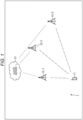
- Fig. 1 is a diagram illustrating a configuration example of a wireless communication system according to a first embodiment of the present technology.
- a wireless communication system 1 in Fig. 1 is a wireless communication system for realizing the LPWA network service described above.
- the wireless communication system 1 includes one terminal 11, three base stations 12-1 to 12-3, and a cloud server 13. Note that the base stations 12-1 to 12-3 are referred to as base stations 12 in a case where it is not particularly necessary to distinguish them.
- the terminal 11 and the base station 12 are connected by wireless communication.
- the base station 12 and the cloud server 13 are connected by wireless communication. Note that the base station 12 and the cloud server 13 may be connected by wired communication.
- BaseStationID which is unique identification information for identifying the base station, is allocated to the base station 12 in advance. Note that the BSID can be set from the cloud server 13. The BSID can be changed only in a case where the BSID is synchronously changed in all the base stations 12.
- the terminal 11 receives, for example, a frame in which signal strength (RSSI: Received Signal Strength Indicator) is the highest among BSID frames including the BSID transmitted from the base station 12.
- RSSI Received Signal Strength Indicator
- the terminal 11 extracts the BSID from the frame in which the signal strength is the highest.
- the terminal 11 transmits a DL request frame for making a DL request for desired data included in the cloud server 13 to the base station 12 of the extracted BSID.
- the terminal 11 receives a data frame corresponding to the desired data from the base station 12 to which the DL request frame has been transmitted.
- the frequency hopping technology is used for wireless communication between the terminal 11 and the base station 12.
- the base station 12 broadcasts the BSID frame at a specific time at a frequency determined by the specific time information. In a case where the base station 12 receives the DL request frame of the desired data in the cloud server 13 from the terminal 11, the base station 12 acquires the desired data from the cloud server 13. The base station 12 transmits a data frame corresponding to the data acquired from the cloud server 13 to the terminal 11.
- the cloud server 13 includes, for example, a content server that distributes content or the like on a cloud.
- the cloud server 13 transmits the desired data to the terminal 11 via the base station 12 that makes an acquisition request for the desired data from the terminal 11.
- Fig. 1 one terminal 11 is illustrated for convenience of description, but there may be a plurality of terminals 11. Similarly, although three base stations 12 are illustrated in Fig. 1 , the number of the base stations 12 may be two or four or more.
- Fig. 2 is a block diagram illustrating a first configuration example of a communication device to which the present technology is applied.
- the communication device illustrated in Fig. 2 is a communication device that operates as the terminal 11.
- the communication device includes a global positioning system (GPS) reception unit 31, an internal clock 32, a parameter holding unit 33, a wireless resource calculation unit 34, a frame generation unit 35, a wireless transmission unit 36, a wireless control unit 37, a wireless reception unit 38, a frame detection unit 39, a frame demodulation unit 40, and a sensor 41.
- GPS global positioning system
- the GPS reception unit 31 receives a GPS signal from GPS satellites and acquires time information.
- the internal clock 32 acquires the time information from the GPS reception unit 31, and calculates the current time by measuring the elapsed time from the acquired time point.
- the internal clock 32 outputs the current time to the wireless control unit 37 and the wireless resource calculation unit 34.
- the parameter holding unit 33 holds a frequency determined by the specific time information at a specific time when a BSID frame is transmitted from the base station 12. Furthermore, the parameter holding unit 33 holds the BSID allocated to all the base stations 12, and the frequency hopping pattern (for example, the frequency, the hopping period, and the reference time) determined by the BSID and the time information.
- the wireless resource calculation unit 34 determines a time, a frequency, and codes (a SYNC code and a scramble code) at and with which a UL frame is transmitted to base station 12 on the basis of the information obtained from the internal clock 32 and the parameter holding unit 33.
- the wireless resource calculation unit 34 determines a time, a frequency, and codes at and with which the BSID frame and a DL frame are received from the base station 12 on the basis of the information obtained from the internal clock 32 and the parameter holding unit 33.
- the wireless resource calculation unit 34 outputs information of the determined time, frequency, and codes to the frame generation unit 35, the wireless control unit 37, the frame detection unit 39, and the frame demodulation unit 40.
- the frame generation unit 35 generates the UL frame to be transmitted to the base station 12 on the basis of a code obtained from the wireless resource calculation unit 34.
- a code obtained from the wireless resource calculation unit 34.
- sensor information acquired by the sensor 41 is stored.
- the wireless transmission unit 36 transmits a wireless signal. Specifically, under the control of the wireless control unit 37, the wireless transmission unit 36 converts the UL frame generated by the frame generation unit 35 into a wireless signal and transmits the wireless signal by a radio wave.
- the wireless control unit 37 acquires the current time from the internal clock 32, and control the wireless transmission unit 36 so as to transmit the UL frame at the transmission time and the transmission frequency obtained from the wireless resource calculation unit 34. Furthermore, the wireless control unit 37 acquires, from the wireless resource calculation unit 34, a time and a frequency at which the BSID frame and the DL frame are received from the base station 12, and controls the wireless reception unit 38 so as to perform reception processing at the corresponding time and frequency.
- the wireless reception unit 38 receives a wireless signal. Specifically, under the control of the wireless control unit 37, the wireless reception unit 38 receives a radio wave, converts the radio wave into a wireless signal, and passes the wireless signal to the frame detection unit 39.
- the frame detection unit 39 detects a frame from a received signal received by the wireless reception unit 38. Specifically, the frame detection unit 39 extracts a signal of a target frequency from a broadband signal, generates a plurality of synchronization patterns (known sequences) from the SYNC code and a plurality of the scramble codes determined by the wireless resource calculation unit 34, calculates signal strength that is a correlation value between each synchronization pattern and the received signal, and determines that the frame has been detected in a case where the signal strength is a certain value or more.
- synchronization patterns known sequences
- the frame demodulation unit 40 demodulates a frame from the received signal. Specifically, the frame demodulation unit 40 descrambles the received signal using the scramble code calculated by the wireless resource calculation unit 34 on the basis of the time when the frame detection unit 39 detects the frame. Thereafter, the frame demodulation unit 40 extracts a payload of the frame from the received signal, and performs decoding processing of an error correction code and error correction using a cyclic redundancy code (CRC) .
- CRC cyclic redundancy code
- the sensor 41 includes a sensor element that acquires information of the outside or inside of the terminal 11.
- the sensor information acquired by the sensor 41 is stored in a frame to be transmitted to the base station 12.
- the sensor 41 includes, for example, a temperature sensor or an acceleration sensor. In a case where it is desired to acquire position information as the sensor information, the GPS reception unit 31 may also serve as the sensor 41.
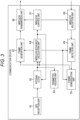
- Fig. 3 is a block diagram illustrating a second configuration example of a communication device to which the present technology is applied.
- the communication device illustrated in Fig. 3 is a communication device that operates as the base station 12.
- the communication device includes a GPS reception unit 61, an internal clock 62, a parameter holding unit 63, a wireless resource calculation unit 64, a frame generation unit 65, a wireless transmission unit 66, a wireless control unit 67, a wireless reception unit 68, a frame detection unit 69, and a frame demodulation unit 70.
- the GPS reception unit 61 to the frame demodulation unit 70 in Fig. 3 have the same configurations as the GPS reception unit 31 to the frame demodulation unit 40 in Fig. 2 , respectively, and thus the description thereof will be omitted.
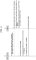
- Fig. 4 is a diagram illustrating a DL sequence in the first embodiment.
- Fig. 5 is appropriately referred to in describing the DL sequence in Fig. 4 .
- Fig. 5 is a diagram schematically illustrating the DL sequence in Fig. 4 in the wireless communication system 1 in Fig. 1 .
- step S1 all the base stations 12 broadcast their own BSID frames at a specific time at a frequency determined by the specific time information so that the terminal 11 can receive the BSID frames (dashed arrows in Fig. 5 ). That is, the BSID frame is simultaneously transmitted from each base station 12.
- the payload of the BSID frame may include accompanying information such as time information in addition to the BSID.
- step S2 the terminal 11 receives the BSID frame at the specific time at the frequency determined by the specific time information.
- step S3 the terminal 11 demodulates the BSID frame, and acquires the BSID from the payload of the demodulated BSID frame.
- the terminal 11 prepares a plurality of synchronization patterns, calculates signal strength for all the synchronization patterns, synchronizes the synchronization pattern in which the signal strength is the highest, and detects the BSID frame. For example, in the case of Fig. 5 , since the base station 12-1 is closest to the terminal 11, the BSID frame transmitted from the base station 12-1 is detected by synchronizing the synchronization pattern in which the signal strength is the highest.
- the terminal 11 demodulates the detected BSID frame and extracts the BSID from the payload of the demodulated BSID frame.
- step S4 the terminal 11 inserts the extracted BSID into a DL request frame and transmits the DL request frame in order to request the DL frame transmission (a dashed-dotted line arrow in Fig. 5 ).
- step S5 the base station 12-1 receives the DL request frame and checks whether the BSID of the DL request frame matches its own ID.
- step S6 in a case where the DL request frame is a request for DL frame transmission to the base station 12-1, the base station 12-1 acquires desired data from the cloud server 13 to the terminal 11 (white arrows in Fig. 5 ).
- step S7 the base station 12-1 transmits the acquired desired data to the terminal 11 as a data frame.
- the base station 12-1 transmits the data frame using the frequency hopping pattern determined from the BSID and the time information as described above (a solid arrow in Fig. 5 ).
- step S8 the terminal 11 receives the data frame transmitted from the base station 12-1 by using the frequency hopping pattern of the base station 12-1, the frequency hopping pattern being determined from the BSID and the time information.
- the terminal 11 can receive the BSID frame and obtain, from the BSID and the time information, the frequency hopping pattern for receiving the data frame.
- the BSID frames are transmitted on the same time and channel at all the base stations. Therefore, in order to enhance the interference resistance, the synchronization pattern is changed according to the BSID. As a result, even if the BSID frames interfere with each other, the synchronization pattern is different, so that the interference resistance of the BSID frames is improved.
- the terminal 11 can obtain necessary information from the base station 12 without making a request to the base station 12.
- Fig. 6 is a diagram illustrating an application example of the wireless communication system 1 in Fig. 1 .
- the terminal 11 In a case where the user uses the terminal 11 across regions, the terminal 11 needs to change a transmission profile such as frequency. Since the region is unknown in the communication of only UL frame transmission, the user needs to manually change the transmission profile of the terminal 11.
- the BSID of the base station 12 is different for each region.
- the terminal 11 can determine the region by receiving the BSID frame from the base station 12.
- Fig. 6 illustrates an example in which the BSID of the base station 12-1 is allocated to the region A, and the BSID of the base station 12-3 is allocated to the region B.
- the terminal 11 determines that the region is the region A, switches to the transmission profile of the region A, and performs the UL frame transmission.
- the terminal 11 determines that the region is the region B, switches to the transmission profile of the region B, and performs the UL frame transmission.
- the transmission profile can be easily switched in the UL frame transmission.
- Fig. 7 is a flowchart for explaining a region determination processing of the terminal 11.
- a conversion table for associating the BSID and the region is stored in advance in the parameter holding unit 33 of the terminal 11.
- step S51 the wireless control unit 37 waits until it is determined that a certain period of time has elapsed. In a case where it is determined in step S51 that the certain time has elapsed, the process proceeds to step S52.
- the base station 12 broadcasts its own BSID frame at a specific time at a frequency determined by the specific time information.
- the BSID frame is not limited to broadcast, and the base station 12 may transmit the BSID frame to the individual terminal 11.
- step S52 the wireless reception unit 38 receives a BSID frame at a specific time at a frequency determined by the specific time information under the control of the wireless control unit 37.
- step S53 the frame detection unit 39 calculates the signal strength for all the synchronization patterns, synchronizes the synchronization pattern in which the signal strength is the highest, and detects the BSID frame.
- the frame demodulation unit 40 demodulates the detected BSID frame and extracts the BSID from the payload of the demodulated BSID frame.
- step S54 the wireless resource calculation unit 34 specifies a region for the terminal 11 to stay using the extracted BSID and the conversion table.
- step S55 a wireless communication unit 37 switches the transmission profile to a transmission profile suitable for the specified region. Thereafter, the process returns to step S51, and the subsequent processes are repeated.
- the terminal does not need to manually change the transmission profile each time the terminal moves across regions, and can efficiently transmit the UL frame.
- Fig. 8 is a diagram illustrating a configuration example of a base station load distribution control system according to a second embodiment of the present technology.
- a base station load distribution control system 101 in Fig. 8 is a wireless communication system for realizing the LPWA network service, similarly to the wireless communication system 1 in Fig. 1 .
- the terminal 11 when receiving the BSID frame, the terminal 11 detects the base station 12 in which the signal strength is the highest, and transmits the DL request frame to the base station 12.
- the base station 12 installed in a place where visibility is good, such as a high-rise building or a high ground, the signal strength tends to be always higher than the other base stations 12, and there is a concern that DL request frames are concentrated.
- the base station load distribution control system 101 will be described in which a terminal 111 itself avoids transmitting a DL request frame to a base station 112-1 installed on a high ground in which load is concentrated, and transmits the DL request frame to a base station 112 having a load lower than that of the base station 112-1.
- the base station load distribution control system 101 includes one terminal 111, three base stations 112-1 to 112-3, and a management server 113.
- base stations 112-1 to 112-3 are referred to as base stations 112 in a case where it is not particularly necessary to distinguish them.
- the terminal 111 and the base station 112 are connected by wireless communication.
- the base station 112 and the management server 113 are connected by wireless communication. Note that the base station 112 and the management server 113 may be connected by wired communication.
- the BSID is allocated to the base station 112 in advance, similarly to the base station 12 in Fig. 1 .
- the terminal 111 receives a BSID frame in which the signal strength is the highest among the BSID frames transmitted from the base station 112. In a case where the terminal 111 determines that there is a concentration flag in the BSID frame in which the signal strength is the highest, the terminal 111 extracts the BSID from the BSID frame in which the signal strength is the second highest.
- the terminal 111 transmits a DL request frame of desired data included in the cloud server 13 to the base station 112 of the extracted BSID, and receives a data frame corresponding to the desired data from the base station 12.
- the frequency hopping technology is used for wireless communication between the terminal 111 and the base station 112.
- the base station 112 In a case of receiving the notification of concentration to the base station 112 from the management server 113, the base station 112 sets the concentration flag in the BSID frame.
- the base station 112 broadcasts the BSID frame at a specific time at a frequency determined by the specific time information.
- the base station 112 In a case receiving a DL request frame of desired data in the cloud server 13 from the terminal 111, the base station 112 acquires the desired data from the cloud server 13. The base station 112 transmits a data frame corresponding to the acquired data to the terminal 111.
- the management server 113 is a server that monitors concentration of DL request frames to the base station 112 on the cloud. In a case where the concentration of the DL request frames to a certain base station 112 exceeds a predetermined threshold value, the management server 113 notifies the base station 112 of the concentration of the DL request frames to the base station 112.
- the numbers and configurations of the communication devices operating as the terminals 111 and the communication devices operating as the base stations 112 are similar to the numbers and configurations of the terminals 11 and the base stations 12 described above with reference to Figs. 1 to 3 .
- the cloud server 13 and the management server 113 may be configured as one device.
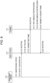
- Fig. 9 is a diagram illustrating a DL sequence in the second embodiment.
- Fig. 10 is appropriately referred to in describing the DL sequence in Fig. 9 .
- Fig. 10 is a diagram schematically illustrating the DL sequence in Fig. 9 in the base station load distribution control system 101 in Fig. 8 .
- step S111 the management server 113 monitors the base station 112.
- step S112 the management server 113 notifies the base station 112 of the concentration of the DL request to the base station 112 (a white arrow in Fig. 10 ) .
- step S113 the base station 112 receives the notification of the concentration of the DL request.
- step S114 the base station 112 that has received the notification of the concentration of the DL request sets the concentration flag in the payload of the BSID frame.
- step S115 the base station 112 broadcasts the BSID frame at a specific time at a frequency determined by the specific time information (dashed arrows in Fig. 10 ) .
- step S116 the terminal 111 receives the BSID frame.
- step S117 the terminal 111 performs first demodulation processing. That is, the terminal 111 prepares a plurality of synchronization patterns, calculates signal strength for all the synchronization patterns, synchronizes the synchronization pattern in which the signal strength is the highest, and detects the BSID frame. For example, in the case of Fig. 5 , since the base station 12-1, which is close to the terminal 11, is installed on a high ground, the BSID frame transmitted from the base station 12-1 is detected by synchronizing a synchronization pattern in which the signal strength is the highest. The terminal 111 performs the first demodulation processing on the detected BSID frame.
- step S118 in a case where there is a concentration flag in the payload of the BSID frame on which the first demodulation processing has been performed, the terminal 111 performs second demodulation processing. That is, in a case where there is a concentration flag in the payload of the demodulated BSID frame, the terminal 111 synchronizes the synchronization pattern in which the signal strength is the second highest, and detects the BSID frame transmitted from the base station 12-3. The terminal 111 performs the second demodulation processing on the detected BSID frame.
- the above-described second demodulation processing may be performed only in a case where there is a concentration flag in the payload of the BSID frame on which the first demodulation processing has been performed and the second highest signal strength is the threshold value.
- step S119 the terminal 11 extracts the BSID from the payload of the BSID frame on which the second demodulation processing has been performed, inserts the extracted BSID into a DL request frame, and transmits the DL request frame in order to request the DL frame transmission (a solid arrow in Fig. 10 ).
- the BSID is extracted from the payload of the BSID frame subjected to the 11-th demodulation processing and included in the DL request frame.
- step S120 the base station 12-3 receives the DL request frame and checks whether the BSID of the DL request frame matches its own ID. Note that the subsequent processing is similar to the processing after step S7 in Fig. 4 , and thus illustration and description thereof are omitted.
- the concentration flag is set to the BSID frame periodically broadcast by the base station 12, so that the terminal 11 can demodulate the BSID frame in which the signal strength is the second highest.
- Fig. 11 is a flowchart illustrating processing of the terminal 111 in the DL sequence in Fig. 9 .
- step S151 the wireless reception unit 38 receives the BSID frame at a specific time at a frequency determined by the specific time information.
- step S152 the frame detection unit 39 extracts a signal of a target frequency from a broadband signal, and generates a plurality of synchronization patterns from the SYNC code and a plurality of the scramble codes determined by the wireless resource calculation unit 34.
- step S153 the frame detection unit 39 calculates signal strength that is a correlation value between each synchronization pattern and the received signal.
- step S154 the frame detection unit 39 synchronizes the synchronization pattern in which the signal strength is the highest.
- step S155 the frame demodulation unit 40 performs the first demodulation processing on the BSID frame in which the signal strength is the highest, and acquires the payload.
- step S156 the frame detection unit 39 determines whether or not there is a concentration flag in the acquired payload. In a case where it is determined in step S156 that there is a concentration flag in the payload, the process proceeds to step S157.
- step S157 the frame detection unit 39 synchronizes the synchronization pattern in which the signal strength is the second highest.
- step S158 the frame demodulation unit 40 performs the second demodulation processing on the BSID frame in which the signal strength is the second highest, and acquires the payload.
- step S159 the frame demodulation unit 40 acquires the BSID from the payload of the BSID frame in which the signal strength is the second highest.
- the frame demodulation unit 40 outputs the acquired BSID frame to the wireless resource calculation unit 34 and the frame generation unit 35.
- step S156 In a case where it is determined in step S156 that there is no concentration flag in the payload, the process proceeds to step S160.
- step S160 the frame demodulation unit 40 extracts the BSID from the payload of the BSID frame in which the signal strength is the highest.
- the frame demodulation unit 40 outputs the extracted BSID frame to the wireless resource calculation unit 34 and the frame generation unit 35.
- step S159 or S160 the process proceeds to step S161.
- step S161 the wireless transmission unit 36 transmits the DL request frame on the basis of the extracted BSID.
- the wireless resource calculation unit 34 determines a time, a frequency, and a code at and with which the UL frame is transmitted to the base station 12 on the basis of the internal clock 32, the BSID supplied from the frame demodulation unit 40, and the information obtained from the parameter holding unit 33.
- the determined time, frequency, and code are output to the wireless transmission unit 36, the wireless control unit 37, and the like.
- the frame generation unit 35 generates a DL request frame including the BSID supplied from the frame demodulation unit 40, and outputs the generated DL request frame to the wireless transmission unit 36.
- the wireless transmission unit 36 transmits a DL request frame to the base station corresponding to the BSID under the control of the wireless control unit 37.
- control to transmit a BSID frame including a BSID for identifying a base station and control to acquire data from a cloud to a terminal on the basis of a DL request frame and to transmit a data frame including the acquired data to the terminal in a case where the BSID included in the DL request frame transmitted from the terminal on the basis of the BSID matches its own BSID are performed.
- control to receive a BSID frame including a BSID for identifying a base station transmitted from a base station, control to transmit a DL request frame for data transmission on the basis of the BSID extracted from the BSID frame in which the signal power is the largest among the received BSID frames, and control to receive a data frame acquired by the base station from the cloud and transmitted by the base station on the basis of the DL request frame are performed.
- the series of processing described above can be executed by hardware and also can be executed by software.
- a program constituting the software is installed on a computer built into dedicated hardware or a general-purpose personal computer from a program recording medium, or the like.
- Fig. 12 is a block diagram illustrating a configuration example of hardware of a computer that performs the series of processing described above in accordance with a program.
- a central processing unit (CPU) 301, a read only memory (ROM) 302, and a random access memory (RAM) 303 are mutually connected by a bus 304.
- an input/output interface 305 is connected to the bus 304.
- An input unit 306 including a keyboard, a mouse, and the like, and an output unit 307 including a display, a speaker, and the like are connected to the input/output interface 305.
- a storage unit 308 including a hard disk, a nonvolatile memory, or the like, a communication unit 309 including a network interface or the like, and a drive 310 that drives a removable medium 311 are connected to the input/output interface 305.
- the series of processing described above is performed, for example, by the CPU 301 loading the program stored in the storage unit 308 into the RAM 303 via the input/output interface 305 and the bus 304 and executing the program.
- the program to be executed by the CPU 301 is provided, for example, by being recorded on the removable medium 311 or via a wired or wireless transmission medium such as a local area network, the Internet, or digital broadcasting and is installed in the storage unit 308.
- a program to be executed by the computer may be a program by which processes are performed in time series in the order described in the present specification, or may be a program by which processes are performed in parallel or a process may be performed at a required time such as when a call is made.
- a system means an assembly of a plurality of components (devices, modules (parts), and the like), and it does not matter whether or not all the components are located in the same housing. Therefore, a plurality of devices housed in separate housings and connected via a network, and one device having a plurality of modules included in one housing are both systems.
- Embodiments of the present technology are not limited to the above-described embodiments, and various modifications may be made without departing from the gist of the present technology.
- the present technology may be configured as cloud computing in which one function is shared by a plurality of devices via a network and processing is executed in cooperation.
- each of the steps in the flowcharts described above can be executed by one device or executed by a plurality of devices in a shared manner.
- the plurality of parts of processing included in one step can be executed by one device or by a plurality of devices in a shared manner.
- the present technology may also have the following configurations.
Landscapes
- Engineering & Computer Science (AREA)
- Computer Security & Cryptography (AREA)
- Computer Networks & Wireless Communication (AREA)
- Signal Processing (AREA)
- Mobile Radio Communication Systems (AREA)
Abstract
Description
- The present technology relates to a wireless communication device, a wireless communication terminal, and a wireless communication method, and more particularly relates to a wireless communication device, a wireless communication terminal, and a wireless communication method capable of avoiding frame interference between base stations.
- Currently, low power wide area (LPWA) network services suitable for the Internet of Things (IoT) are provided. Since a communication distance in the LPWA network service is long, frames from a plurality of base stations may arrive at the terminal. Therefore, in a case where a frequency hopping between the base stations is the same, the frames always collide with each other.
- Therefore, in the uplink (UL: UpLink) of the LPWA network service, when the base station exchanges with a plurality of terminals, the terminals multiplex data frames in a frequency (channel) direction and a time direction by using a pseudo-random algorithm and transmit the frames to the base station (see Patent Document 1).
- Since the base station can receive a plurality of frequencies, frames transmitted from the plurality of terminals can be demodulated simultaneously.
- Patent Document 1:
WO 2017/016262 - However, in the downlink (DL: Down Link) of the LPWA network service, the terminal can receive only one frequency because of a reduction in a processing amount on the terminal side.
- The present technology has been made in view of such a situation, and an object thereof is to avoid frame interference between base stations.
- A wireless communication device according to a first aspect of the present technology includes a communication control unit that performs control to transmit an identification frame including identification information for identifying a base station, and control to acquire data from a cloud to a wireless communication terminal on the basis of the request frame and transmit a data frame including the acquired data to the wireless communication terminal in a case where the identification information included in a request frame transmitted from the wireless communication terminal on the basis of the identification information matches the identification information of its own.
- A wireless communication terminal according to a second aspect of the present technology includes a communication control unit that performs control to receive an identification frame including identification information for identifying a base station transmitted from a wireless communication device, control to transmit a request frame for data transmission on the basis of the identification information extracted from the identification frame in which signal strength is the highest among the received identification frames, and control to receive a data frame acquired by the wireless communication device from a cloud on the basis of the request frame and transmitted by the wireless communication device.
- In the first aspect of the present technology, control to transmit an identification frame including identification information for identifying a base station, and control to acquire data from a cloud to a wireless communication terminal on the basis of the request frame and transmit a data frame including the acquired data to the wireless communication terminal in a case where the identification information included in a request frame transmitted from the wireless communication terminal on the basis of the identification information matches the identification information of its own are performed.
- In the second aspect of the present technology, control to receive an identification frame including identification information for identifying a base station transmitted from a wireless communication device, control to transmit a request frame for data transmission on the basis of the identification information extracted from the identification frame in which signal strength is the highest among the received identification frames, and control to receive a data frame acquired by the wireless communication device from a cloud on the basis of the request frame and transmitted by the wireless communication device are performed.
-
-
Fig. 1 is a diagram illustrating a configuration example of a wireless communication system according to a first embodiment of the present technology. -
Fig. 2 is a block diagram illustrating a first configuration example of a communication device to which the present technology is applied. -
Fig. 3 is a block diagram illustrating a second configuration example of a communication device to which the present technology is applied. -
Fig. 4 is a diagram illustrating a DL sequence in the first embodiment. -
Fig. 5 is a diagram schematically illustrating the DL sequence inFig. 4 in the wireless communication system ofFig. 1 . -
Fig. 6 is a diagram illustrating an application example of the wireless communication system inFig. 1 . -
Fig. 7 is a flowchart for explaining a region determination processing of a terminal. -
Fig. 8 is a diagram illustrating a configuration example of a base station load distribution control system according to a second embodiment of the present technology. -
Fig. 9 is a diagram illustrating a DL sequence in the second embodiment. -
Fig. 10 is a diagram schematically illustrating the DL sequence inFig. 9 in the base station load distribution control system ofFig. 8 . -
Fig. 11 is a flowchart illustrating processing of a terminal in the DL sequence inFig. 9 . -
Fig. 12 is a block diagram illustrating a configuration example of a computer. - Hereinafter, modes for carrying out the present technology will be described. The description will be given in the following order.
- 1. First Embodiment (Wireless Communication System)
- 2. Application Example
- 3. Second Embodiment (Base Station Load Distribution Control System)
- 4. Others
-
Fig. 1 is a diagram illustrating a configuration example of a wireless communication system according to a first embodiment of the present technology. - A
wireless communication system 1 inFig. 1 is a wireless communication system for realizing the LPWA network service described above. - The
wireless communication system 1 includes oneterminal 11, three base stations 12-1 to 12-3, and acloud server 13. Note that the base stations 12-1 to 12-3 are referred to asbase stations 12 in a case where it is not particularly necessary to distinguish them. - The
terminal 11 and thebase station 12 are connected by wireless communication. Thebase station 12 and thecloud server 13 are connected by wireless communication. Note that thebase station 12 and thecloud server 13 may be connected by wired communication. - BaseStationID (BSID), which is unique identification information for identifying the base station, is allocated to the
base station 12 in advance. Note that the BSID can be set from thecloud server 13. The BSID can be changed only in a case where the BSID is synchronously changed in all thebase stations 12. - The
terminal 11 receives, for example, a frame in which signal strength (RSSI: Received Signal Strength Indicator) is the highest among BSID frames including the BSID transmitted from thebase station 12. Theterminal 11 extracts the BSID from the frame in which the signal strength is the highest. - The
terminal 11 transmits a DL request frame for making a DL request for desired data included in thecloud server 13 to thebase station 12 of the extracted BSID. Theterminal 11 receives a data frame corresponding to the desired data from thebase station 12 to which the DL request frame has been transmitted. The frequency hopping technology is used for wireless communication between theterminal 11 and thebase station 12. - The
base station 12 broadcasts the BSID frame at a specific time at a frequency determined by the specific time information. In a case where thebase station 12 receives the DL request frame of the desired data in thecloud server 13 from theterminal 11, thebase station 12 acquires the desired data from thecloud server 13. Thebase station 12 transmits a data frame corresponding to the data acquired from thecloud server 13 to theterminal 11. - The
cloud server 13 includes, for example, a content server that distributes content or the like on a cloud. Thecloud server 13 transmits the desired data to theterminal 11 via thebase station 12 that makes an acquisition request for the desired data from theterminal 11. - Note that, in
Fig. 1 , oneterminal 11 is illustrated for convenience of description, but there may be a plurality ofterminals 11. Similarly, although threebase stations 12 are illustrated inFig. 1 , the number of thebase stations 12 may be two or four or more. -
Fig. 2 is a block diagram illustrating a first configuration example of a communication device to which the present technology is applied. - The communication device illustrated in
Fig. 2 is a communication device that operates as the terminal 11. - The communication device includes a global positioning system (GPS)
reception unit 31, aninternal clock 32, aparameter holding unit 33, a wirelessresource calculation unit 34, aframe generation unit 35, awireless transmission unit 36, awireless control unit 37, awireless reception unit 38, aframe detection unit 39, aframe demodulation unit 40, and asensor 41. - The
GPS reception unit 31 receives a GPS signal from GPS satellites and acquires time information. - The
internal clock 32 acquires the time information from theGPS reception unit 31, and calculates the current time by measuring the elapsed time from the acquired time point. Theinternal clock 32 outputs the current time to thewireless control unit 37 and the wirelessresource calculation unit 34. - The
parameter holding unit 33 holds a frequency determined by the specific time information at a specific time when a BSID frame is transmitted from thebase station 12. Furthermore, theparameter holding unit 33 holds the BSID allocated to all thebase stations 12, and the frequency hopping pattern (for example, the frequency, the hopping period, and the reference time) determined by the BSID and the time information. - The wireless
resource calculation unit 34 determines a time, a frequency, and codes (a SYNC code and a scramble code) at and with which a UL frame is transmitted tobase station 12 on the basis of the information obtained from theinternal clock 32 and theparameter holding unit 33. The wirelessresource calculation unit 34 determines a time, a frequency, and codes at and with which the BSID frame and a DL frame are received from thebase station 12 on the basis of the information obtained from theinternal clock 32 and theparameter holding unit 33. The wirelessresource calculation unit 34 outputs information of the determined time, frequency, and codes to theframe generation unit 35, thewireless control unit 37, theframe detection unit 39, and theframe demodulation unit 40. - The
frame generation unit 35 generates the UL frame to be transmitted to thebase station 12 on the basis of a code obtained from the wirelessresource calculation unit 34. In the frame to be transmitted to thebase station 12, for example, sensor information acquired by thesensor 41 is stored. - The
wireless transmission unit 36 transmits a wireless signal. Specifically, under the control of thewireless control unit 37, thewireless transmission unit 36 converts the UL frame generated by theframe generation unit 35 into a wireless signal and transmits the wireless signal by a radio wave. - The
wireless control unit 37 acquires the current time from theinternal clock 32, and control thewireless transmission unit 36 so as to transmit the UL frame at the transmission time and the transmission frequency obtained from the wirelessresource calculation unit 34. Furthermore, thewireless control unit 37 acquires, from the wirelessresource calculation unit 34, a time and a frequency at which the BSID frame and the DL frame are received from thebase station 12, and controls thewireless reception unit 38 so as to perform reception processing at the corresponding time and frequency. - The
wireless reception unit 38 receives a wireless signal. Specifically, under the control of thewireless control unit 37, thewireless reception unit 38 receives a radio wave, converts the radio wave into a wireless signal, and passes the wireless signal to theframe detection unit 39. - The
frame detection unit 39 detects a frame from a received signal received by thewireless reception unit 38. Specifically, theframe detection unit 39 extracts a signal of a target frequency from a broadband signal, generates a plurality of synchronization patterns (known sequences) from the SYNC code and a plurality of the scramble codes determined by the wirelessresource calculation unit 34, calculates signal strength that is a correlation value between each synchronization pattern and the received signal, and determines that the frame has been detected in a case where the signal strength is a certain value or more. - The
frame demodulation unit 40 demodulates a frame from the received signal. Specifically, theframe demodulation unit 40 descrambles the received signal using the scramble code calculated by the wirelessresource calculation unit 34 on the basis of the time when theframe detection unit 39 detects the frame. Thereafter, theframe demodulation unit 40 extracts a payload of the frame from the received signal, and performs decoding processing of an error correction code and error correction using a cyclic redundancy code (CRC) . - The
sensor 41 includes a sensor element that acquires information of the outside or inside of the terminal 11. The sensor information acquired by thesensor 41 is stored in a frame to be transmitted to thebase station 12. - The
sensor 41 includes, for example, a temperature sensor or an acceleration sensor. In a case where it is desired to acquire position information as the sensor information, theGPS reception unit 31 may also serve as thesensor 41. -
Fig. 3 is a block diagram illustrating a second configuration example of a communication device to which the present technology is applied. - The communication device illustrated in
Fig. 3 is a communication device that operates as thebase station 12. - The communication device includes a
GPS reception unit 61, aninternal clock 62, aparameter holding unit 63, a wirelessresource calculation unit 64, aframe generation unit 65, awireless transmission unit 66, awireless control unit 67, awireless reception unit 68, aframe detection unit 69, and aframe demodulation unit 70. - The
GPS reception unit 61 to theframe demodulation unit 70 inFig. 3 have the same configurations as theGPS reception unit 31 to theframe demodulation unit 40 inFig. 2 , respectively, and thus the description thereof will be omitted. -
Fig. 4 is a diagram illustrating a DL sequence in the first embodiment. - Note that
Fig. 5 is appropriately referred to in describing the DL sequence inFig. 4 . -
Fig. 5 is a diagram schematically illustrating the DL sequence inFig. 4 in thewireless communication system 1 inFig. 1 . - In step S1, all the
base stations 12 broadcast their own BSID frames at a specific time at a frequency determined by the specific time information so that the terminal 11 can receive the BSID frames (dashed arrows inFig. 5 ). That is, the BSID frame is simultaneously transmitted from eachbase station 12. - At that time, since the BSID frames always collide, different synchronization patterns are added by each
base station 12 so that the terminal 11 can be synchronized even if the BSID frames collide. Furthermore, the payload of the BSID frame may include accompanying information such as time information in addition to the BSID. - In step S2, the terminal 11 receives the BSID frame at the specific time at the frequency determined by the specific time information.
- In step S3, the terminal 11 demodulates the BSID frame, and acquires the BSID from the payload of the demodulated BSID frame.
- That is, the terminal 11 prepares a plurality of synchronization patterns, calculates signal strength for all the synchronization patterns, synchronizes the synchronization pattern in which the signal strength is the highest, and detects the BSID frame. For example, in the case of
Fig. 5 , since the base station 12-1 is closest to the terminal 11, the BSID frame transmitted from the base station 12-1 is detected by synchronizing the synchronization pattern in which the signal strength is the highest. - The terminal 11 demodulates the detected BSID frame and extracts the BSID from the payload of the demodulated BSID frame.
- In step S4, the terminal 11 inserts the extracted BSID into a DL request frame and transmits the DL request frame in order to request the DL frame transmission (a dashed-dotted line arrow in
Fig. 5 ). - In step S5, the base station 12-1 receives the DL request frame and checks whether the BSID of the DL request frame matches its own ID.
- In step S6, in a case where the DL request frame is a request for DL frame transmission to the base station 12-1, the base station 12-1 acquires desired data from the
cloud server 13 to the terminal 11 (white arrows inFig. 5 ). - In step S7, the base station 12-1 transmits the acquired desired data to the terminal 11 as a data frame. At this time, the base station 12-1 transmits the data frame using the frequency hopping pattern determined from the BSID and the time information as described above (a solid arrow in
Fig. 5 ). - In step S8, the terminal 11 receives the data frame transmitted from the base station 12-1 by using the frequency hopping pattern of the base station 12-1, the frequency hopping pattern being determined from the BSID and the time information.
- As described above, since the
base station 12 periodically broadcasts the BSID frame notifying its own BSID, the terminal 11 can receive the BSID frame and obtain, from the BSID and the time information, the frequency hopping pattern for receiving the data frame. - As a result, interference of the data frames between the
base stations 12 can be avoided, and frame reception performance is improved. - Furthermore, the BSID frames are transmitted on the same time and channel at all the base stations. Therefore, in order to enhance the interference resistance, the synchronization pattern is changed according to the BSID. As a result, even if the BSID frames interfere with each other, the synchronization pattern is different, so that the interference resistance of the BSID frames is improved.
- Note that, as described above, not only the BSID but also accompanying information such as time information can be attached to the BSID frame. In this way, the terminal 11 can obtain necessary information from the
base station 12 without making a request to thebase station 12. -
Fig. 6 is a diagram illustrating an application example of thewireless communication system 1 inFig. 1 . - In a case where the user uses the terminal 11 across regions, the terminal 11 needs to change a transmission profile such as frequency. Since the region is unknown in the communication of only UL frame transmission, the user needs to manually change the transmission profile of the terminal 11.
- Therefore, the BSID of the
base station 12 is different for each region. As a result, the terminal 11 can determine the region by receiving the BSID frame from thebase station 12. - For example,
Fig. 6 illustrates an example in which the BSID of the base station 12-1 is allocated to the region A, and the BSID of the base station 12-3 is allocated to the region B. - As illustrated on the left side of
Fig. 6 , in a case where the terminal 11 receives the BSID frame from the base station 12-1, the terminal 11 determines that the region is the region A, switches to the transmission profile of the region A, and performs the UL frame transmission. - Similarly, as illustrated on the right side of
Fig. 6 , in a case where the terminal 11 receives the BSID frame from the base station 12-3, the terminal 11 determines that the region is the region B, switches to the transmission profile of the region B, and performs the UL frame transmission. - As described above, even when the terminal 11 moves across different regions, the transmission profile can be easily switched in the UL frame transmission.
-
Fig. 7 is a flowchart for explaining a region determination processing of the terminal 11. - Note that, for example, a conversion table for associating the BSID and the region is stored in advance in the
parameter holding unit 33 of the terminal 11. - In step S51, the
wireless control unit 37 waits until it is determined that a certain period of time has elapsed. In a case where it is determined in step S51 that the certain time has elapsed, the process proceeds to step S52. - As described above with reference to
Fig. 4 , thebase station 12 broadcasts its own BSID frame at a specific time at a frequency determined by the specific time information. Note that, in the case ofFig. 7 , the BSID frame is not limited to broadcast, and thebase station 12 may transmit the BSID frame to theindividual terminal 11. - In step S52, the
wireless reception unit 38 receives a BSID frame at a specific time at a frequency determined by the specific time information under the control of thewireless control unit 37. - In step S53, the
frame detection unit 39 calculates the signal strength for all the synchronization patterns, synchronizes the synchronization pattern in which the signal strength is the highest, and detects the BSID frame. Theframe demodulation unit 40 demodulates the detected BSID frame and extracts the BSID from the payload of the demodulated BSID frame. - In step S54, the wireless
resource calculation unit 34 specifies a region for the terminal 11 to stay using the extracted BSID and the conversion table. - In step S55, a
wireless communication unit 37 switches the transmission profile to a transmission profile suitable for the specified region. Thereafter, the process returns to step S51, and the subsequent processes are repeated. - As described above, the terminal does not need to manually change the transmission profile each time the terminal moves across regions, and can efficiently transmit the UL frame.
-
Fig. 8 is a diagram illustrating a configuration example of a base station load distribution control system according to a second embodiment of the present technology. - A base station load
distribution control system 101 inFig. 8 is a wireless communication system for realizing the LPWA network service, similarly to thewireless communication system 1 inFig. 1 . - In the
wireless communication system 1 of the first embodiment described above, when receiving the BSID frame, the terminal 11 detects thebase station 12 in which the signal strength is the highest, and transmits the DL request frame to thebase station 12. In thebase station 12 installed in a place where visibility is good, such as a high-rise building or a high ground, the signal strength tends to be always higher than theother base stations 12, and there is a concern that DL request frames are concentrated. - Therefore, in the second embodiment, the base station load
distribution control system 101 will be described in which a terminal 111 itself avoids transmitting a DL request frame to a base station 112-1 installed on a high ground in which load is concentrated, and transmits the DL request frame to abase station 112 having a load lower than that of the base station 112-1. - The base station load
distribution control system 101 includes oneterminal 111, three base stations 112-1 to 112-3, and amanagement server 113. - Note that although not illustrated in
Fig. 8 , there is also thecloud server 13 inFig. 1 . Furthermore, the base stations 112-1 to 112-3 are referred to asbase stations 112 in a case where it is not particularly necessary to distinguish them. - The terminal 111 and the
base station 112 are connected by wireless communication. Thebase station 112 and themanagement server 113 are connected by wireless communication. Note that thebase station 112 and themanagement server 113 may be connected by wired communication. - The BSID is allocated to the
base station 112 in advance, similarly to thebase station 12 inFig. 1 . - The terminal 111 receives a BSID frame in which the signal strength is the highest among the BSID frames transmitted from the
base station 112. In a case where the terminal 111 determines that there is a concentration flag in the BSID frame in which the signal strength is the highest, the terminal 111 extracts the BSID from the BSID frame in which the signal strength is the second highest. - The terminal 111 transmits a DL request frame of desired data included in the
cloud server 13 to thebase station 112 of the extracted BSID, and receives a data frame corresponding to the desired data from thebase station 12. The frequency hopping technology is used for wireless communication between the terminal 111 and thebase station 112. - In a case of receiving the notification of concentration to the
base station 112 from themanagement server 113, thebase station 112 sets the concentration flag in the BSID frame. Thebase station 112 broadcasts the BSID frame at a specific time at a frequency determined by the specific time information. - In a case receiving a DL request frame of desired data in the
cloud server 13 from the terminal 111, thebase station 112 acquires the desired data from thecloud server 13. Thebase station 112 transmits a data frame corresponding to the acquired data to the terminal 111. - The
management server 113 is a server that monitors concentration of DL request frames to thebase station 112 on the cloud. In a case where the concentration of the DL request frames to acertain base station 112 exceeds a predetermined threshold value, themanagement server 113 notifies thebase station 112 of the concentration of the DL request frames to thebase station 112. - Note that the numbers and configurations of the communication devices operating as the
terminals 111 and the communication devices operating as thebase stations 112 are similar to the numbers and configurations of theterminals 11 and thebase stations 12 described above with reference toFigs. 1 to 3 . Furthermore, thecloud server 13 and themanagement server 113 may be configured as one device. -
Fig. 9 is a diagram illustrating a DL sequence in the second embodiment. - Note that
Fig. 10 is appropriately referred to in describing the DL sequence inFig. 9 . -
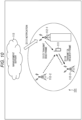
Fig. 10 is a diagram schematically illustrating the DL sequence inFig. 9 in the base station loaddistribution control system 101 inFig. 8 . - In step S111, the
management server 113 monitors thebase station 112. - In a case where the concentration of the DL request to a
certain base station 112 exceeds a predetermined threshold value, in step S112, themanagement server 113 notifies thebase station 112 of the concentration of the DL request to the base station 112 (a white arrow inFig. 10 ) . - In step S113, the
base station 112 receives the notification of the concentration of the DL request. - In step S114, the
base station 112 that has received the notification of the concentration of the DL request sets the concentration flag in the payload of the BSID frame. - In step S115, the
base station 112 broadcasts the BSID frame at a specific time at a frequency determined by the specific time information (dashed arrows inFig. 10 ) . - In step S116, the terminal 111 receives the BSID frame.
- In step S117, the terminal 111 performs first demodulation processing. That is, the terminal 111 prepares a plurality of synchronization patterns, calculates signal strength for all the synchronization patterns, synchronizes the synchronization pattern in which the signal strength is the highest, and detects the BSID frame. For example, in the case of
Fig. 5 , since the base station 12-1, which is close to the terminal 11, is installed on a high ground, the BSID frame transmitted from the base station 12-1 is detected by synchronizing a synchronization pattern in which the signal strength is the highest. The terminal 111 performs the first demodulation processing on the detected BSID frame. - In step S118, in a case where there is a concentration flag in the payload of the BSID frame on which the first demodulation processing has been performed, the terminal 111 performs second demodulation processing. That is, in a case where there is a concentration flag in the payload of the demodulated BSID frame, the terminal 111 synchronizes the synchronization pattern in which the signal strength is the second highest, and detects the BSID frame transmitted from the base station 12-3. The terminal 111 performs the second demodulation processing on the detected BSID frame.
- Note that, as a determination condition in step S118, the above-described second demodulation processing may be performed only in a case where there is a concentration flag in the payload of the BSID frame on which the first demodulation processing has been performed and the second highest signal strength is the threshold value.
- In step S119, the terminal 11 extracts the BSID from the payload of the BSID frame on which the second demodulation processing has been performed, inserts the extracted BSID into a DL request frame, and transmits the DL request frame in order to request the DL frame transmission (a solid arrow in
Fig. 10 ). - Note that, in a case where the second demodulation processing is not performed, the BSID is extracted from the payload of the BSID frame subjected to the 11-th demodulation processing and included in the DL request frame.
- In step S120, the base station 12-3 receives the DL request frame and checks whether the BSID of the DL request frame matches its own ID. Note that the subsequent processing is similar to the processing after step S7 in
Fig. 4 , and thus illustration and description thereof are omitted. - As described above, in a case where the
management server 113 notifies the concentration of the DL request frame of thebase station 12, the concentration flag is set to the BSID frame periodically broadcast by thebase station 12, so that the terminal 11 can demodulate the BSID frame in which the signal strength is the second highest. - As a result, it is possible to avoid concentration of the DL request frames in the
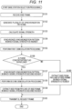
base station 12. -
Fig. 11 is a flowchart illustrating processing of the terminal 111 in the DL sequence inFig. 9 . - In step S151, the
wireless reception unit 38 receives the BSID frame at a specific time at a frequency determined by the specific time information. - In step S152, the
frame detection unit 39 extracts a signal of a target frequency from a broadband signal, and generates a plurality of synchronization patterns from the SYNC code and a plurality of the scramble codes determined by the wirelessresource calculation unit 34. - In step S153, the
frame detection unit 39 calculates signal strength that is a correlation value between each synchronization pattern and the received signal. - In step S154, the
frame detection unit 39 synchronizes the synchronization pattern in which the signal strength is the highest. - In step S155, the
frame demodulation unit 40 performs the first demodulation processing on the BSID frame in which the signal strength is the highest, and acquires the payload. - In step S156, the
frame detection unit 39 determines whether or not there is a concentration flag in the acquired payload. In a case where it is determined in step S156 that there is a concentration flag in the payload, the process proceeds to step S157. - In step S157, the
frame detection unit 39 synchronizes the synchronization pattern in which the signal strength is the second highest. - In step S158, the
frame demodulation unit 40 performs the second demodulation processing on the BSID frame in which the signal strength is the second highest, and acquires the payload. - In step S159, the
frame demodulation unit 40 acquires the BSID from the payload of the BSID frame in which the signal strength is the second highest. Theframe demodulation unit 40 outputs the acquired BSID frame to the wirelessresource calculation unit 34 and theframe generation unit 35. - In a case where it is determined in step S156 that there is no concentration flag in the payload, the process proceeds to step S160.
- In step S160, the
frame demodulation unit 40 extracts the BSID from the payload of the BSID frame in which the signal strength is the highest. Theframe demodulation unit 40 outputs the extracted BSID frame to the wirelessresource calculation unit 34 and theframe generation unit 35. - After step S159 or S160, the process proceeds to step S161.
- In step S161, the
wireless transmission unit 36 transmits the DL request frame on the basis of the extracted BSID. - That is, the wireless
resource calculation unit 34 determines a time, a frequency, and a code at and with which the UL frame is transmitted to thebase station 12 on the basis of theinternal clock 32, the BSID supplied from theframe demodulation unit 40, and the information obtained from theparameter holding unit 33. The determined time, frequency, and code are output to thewireless transmission unit 36, thewireless control unit 37, and the like. Theframe generation unit 35 generates a DL request frame including the BSID supplied from theframe demodulation unit 40, and outputs the generated DL request frame to thewireless transmission unit 36. Thewireless transmission unit 36 transmits a DL request frame to the base station corresponding to the BSID under the control of thewireless control unit 37. - As described above, in the present technology, control to transmit a BSID frame including a BSID for identifying a base station, and control to acquire data from a cloud to a terminal on the basis of a DL request frame and to transmit a data frame including the acquired data to the terminal in a case where the BSID included in the DL request frame transmitted from the terminal on the basis of the BSID matches its own BSID are performed.
- Furthermore, in the present technology, control to receive a BSID frame including a BSID for identifying a base station transmitted from a base station, control to transmit a DL request frame for data transmission on the basis of the BSID extracted from the BSID frame in which the signal power is the largest among the received BSID frames, and control to receive a data frame acquired by the base station from the cloud and transmitted by the base station on the basis of the DL request frame are performed.
- As described above, according to the present technology, frame interference between base stations can be avoided.
- The series of processing described above can be executed by hardware and also can be executed by software. In a case where the series of processing is executed by software, a program constituting the software is installed on a computer built into dedicated hardware or a general-purpose personal computer from a program recording medium, or the like.
-
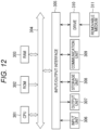
Fig. 12 is a block diagram illustrating a configuration example of hardware of a computer that performs the series of processing described above in accordance with a program. - A central processing unit (CPU) 301, a read only memory (ROM) 302, and a random access memory (RAM) 303 are mutually connected by a
bus 304. - Moreover, an input/
output interface 305 is connected to thebus 304. Aninput unit 306 including a keyboard, a mouse, and the like, and anoutput unit 307 including a display, a speaker, and the like are connected to the input/output interface 305. Furthermore, astorage unit 308 including a hard disk, a nonvolatile memory, or the like, acommunication unit 309 including a network interface or the like, and adrive 310 that drives aremovable medium 311 are connected to the input/output interface 305. - In the computer configured as described above, the series of processing described above is performed, for example, by the
CPU 301 loading the program stored in thestorage unit 308 into theRAM 303 via the input/output interface 305 and thebus 304 and executing the program. - The program to be executed by the
CPU 301 is provided, for example, by being recorded on theremovable medium 311 or via a wired or wireless transmission medium such as a local area network, the Internet, or digital broadcasting and is installed in thestorage unit 308. - Note that, a program to be executed by the computer may be a program by which processes are performed in time series in the order described in the present specification, or may be a program by which processes are performed in parallel or a process may be performed at a required time such as when a call is made.
- Note that, in the present specification, a system means an assembly of a plurality of components (devices, modules (parts), and the like), and it does not matter whether or not all the components are located in the same housing. Therefore, a plurality of devices housed in separate housings and connected via a network, and one device having a plurality of modules included in one housing are both systems.
- Furthermore, the effects described in the present specification are merely examples and not restrictive, and there may also be other effects.
- Embodiments of the present technology are not limited to the above-described embodiments, and various modifications may be made without departing from the gist of the present technology.
- For example, the present technology may be configured as cloud computing in which one function is shared by a plurality of devices via a network and processing is executed in cooperation.
- Furthermore, each of the steps in the flowcharts described above can be executed by one device or executed by a plurality of devices in a shared manner.
- Moreover, in a case where a plurality of parts of processing is included in one step, the plurality of parts of processing included in one step can be executed by one device or by a plurality of devices in a shared manner.
- The present technology may also have the following configurations.
- (1) A wireless communication device including:
a communication control unit that performs control to transmit an identification frame including identification information for identifying a base station, and control to acquire data from a server to a wireless communication terminal on the basis of the request frame and transmit a data frame including the acquired data to the wireless communication terminal in a case where the identification information included in a request frame transmitted from the wireless communication terminal on the basis of the identification information matches the identification information of its own. - (2) The wireless communication device according to (1), in which
the communication control unit performs control to transmit the identification frame at a specific time at a frequency determined by the specific time information. - (3) The wireless communication device according to (1) or (2), in which
the communication control unit performs control to simultaneously transmit the identification frame to another wireless communication device. - (4) The wireless communication device according to any one of (1) to (3), in which
the communication control unit performs control to transmit the identification frame generated by adding a synchronization pattern different for each base station. - (5) The wireless communication device according to any one of (1) to (4), in which
the communication control unit performs control to transmit the data frame in a frequency hopping pattern determined on the basis of the identification information. - (6) The wireless communication device according to any one of (1) to (5), in which
the identification information is separated for each region of the base station. - (7) The wireless communication device according to any one of (1) to (6), further including
a frame generation unit that generates the identification frame by setting a concentration flag indicating that the request frame is concentrated in a payload in a case where a notification of concentration of the request frame transmitted from a management server is received. - (8) A wireless communication method, in which
- a wireless communication device
- performs control to transmit an identification frame including identification information for identifying a base station, and control to acquire data from a server to a wireless communication terminal on the basis of the request frame and transmit a data frame including the acquired data to the wireless communication terminal in a case where the identification information included in a request frame transmitted from the wireless communication terminal on the basis of the identification information matches the identification information of its own.
- (9) A wireless communication terminal including:
a communication control unit that performs control to receive an identification frame transmitted from a base station, the identification frame including identification information for identifying the base station, control to transmit a request frame for data transmission on the basis of the identification information extracted from the identification frame in which signal strength is the highest among the received identification frames, and control to receive a data frame acquired by the base station from a server on the basis of the request frame and transmitted by the base station. - (10) The wireless communication terminal according to (9), in which
the communication control unit performs control to receive the identification frame at a predetermined specific time at a frequency determined by the specific time. - (11) The wireless communication terminal according to any one of (9) to (10), in which
the communication control unit further includes a frame demodulation unit that calculates the signal strength for a plurality of synchronization patterns, demodulates the identification frame received by synchronizing the synchronization pattern in which the signal strength is the highest, and extracts the identification information. - (12) The wireless communication terminal according to any one of (9) to (11), in which
the communication control unit performs control to receive the data frame in a frequency hopping pattern determined on the basis of the extracted identification information. - (13) The wireless communication terminal according to any one of (9) to (12), further including
- a storage unit that stores a conversion table that associates the identification information with a region of the base station,
- in which the communication control unit determines the region on the basis of the extracted identification information.
- (14) The wireless communication terminal according to any one of (9) to (13), in which
the communication control unit performs control to transmit the request frame on the basis of the identification information extracted from the identification frame in which the signal strength is the second highest in a case where a concentration flag indicating that the request frame is concentrated is included in a payload of the identification frame in which the signal strength is the highest. - (15) The wireless communication terminal according to (14), in which
the communication control unit performs control to transmit the request frame on the basis of the identification information extracted from the identification frame in which the signal strength is the second highest in a case where the concentration flag is included in the payload of the identification frame in which the signal strength is the highest and in a case where the signal strength of the identification frame in which the signal strength is the second highest is equal to or greater than a threshold value. - (16) A wireless communication method, in which
- a wireless communication terminal
- performs control to receive an identification frame transmitted from a base station, the identification frame including identification information for identifying the base station, control to transmit a request frame for data transmission on the basis of the identification information extracted from the identification frame in which signal strength is the highest among the received identification frames, and control to receive a data frame acquired by the base station from a server on the basis of the request frame and transmitted by the base station.
-
- 1
- Wireless communication system
- 11
- Wireless communication device
- 12, 12-1 to 12-3
- Base station
- 13
- Cloud server
- 31
- GPS reception unit
- 32
- Internal clock
- 33
- Parameter holding unit
- 34
- Wireless resource calculation unit
- 35
- Frame generation unit
- 36
- Wireless transmission unit
- 37
- Wireless control unit
- 38
- Wireless reception unit
- 37
- Wireless control unit
- 38
- Wireless reception unit
- 39
- Frame reception unit
- 40
- Frame demodulation unit
- 41
- Sensor
- 61
- GPS reception unit
- 62
- Internal clock
- 63
- Parameter holding unit
- 64
- Wireless resource calculation unit
- 65
- Frame generation unit
- 66
- Wireless transmission unit
- 67
- Wireless control unit
- 68
- Wireless reception unit
- 67
- Wireless control unit
- 68
- Wireless reception unit
- 69
- Frame reception unit
- 70
- Frame demodulation unit
- 101
- Base station load distribution control system
- 111
- Terminal
- 112, 112-1 to 112-3
- Base station
- 113
- Management server
Claims (16)
- A wireless communication device comprising:
a communication control unit that performs control to transmit an identification frame including identification information for identifying a base station, and control to acquire data from a server to a wireless communication terminal on a basis of the request frame and transmit a data frame including the acquired data to the wireless communication terminal in a case where the identification information included in a request frame transmitted from the wireless communication terminal on a basis of the identification information matches the identification information of its own. - The wireless communication device according to claim 1, wherein
the communication control unit performs control to transmit the identification frame at a specific time at a frequency determined by the specific time information. - The wireless communication device according to claim 1, wherein
the communication control unit performs control to simultaneously transmit the identification frame to another wireless communication device. - The wireless communication device according to claim 1, wherein
the communication control unit performs control to transmit the identification frame generated by adding a synchronization pattern different for each base station. - The wireless communication device according to claim 1, wherein
the communication control unit performs control to transmit the data frame in a frequency hopping pattern determined on a basis of the identification information. - The wireless communication device according to claim 1, wherein
the identification information is separated for each region of the base station. - The wireless communication device according to claim 1, further comprising
a frame generation unit that generates the identification frame by setting a concentration flag indicating that the request frame is concentrated in a payload in a case where a notification of concentration of the request frame transmitted from a management server is received. - A wireless communication method, whereina wireless communication deviceperforms control to transmit an identification frame including identification information for identifying a base station, and control to acquire data from a server to a wireless communication terminal on a basis of the request frame and transmit a data frame including the acquired data to the wireless communication terminal in a case where the identification information included in a request frame transmitted from the wireless communication terminal on a basis of the identification information matches the identification information of its own.
- A wireless communication terminal comprising:
a communication control unit that performs control to receive an identification frame transmitted from a base station, the identification frame including identification information for identifying the base station, control to transmit a request frame for data transmission on a basis of the identification information extracted from the identification frame in which signal strength is the highest among the received identification frames, and control to receive a data frame acquired by the base station from a server on a basis of the request frame and transmitted by the base station. - The wireless communication terminal according to claim 9, wherein
the communication control unit performs control to receive the identification frame at a predetermined specific time at a frequency determined by the specific time. - The wireless communication terminal according to claim 9, wherein
the communication control unit further comprises a frame demodulation unit that calculates the signal strength for a plurality of synchronization patterns, demodulates the identification frame received by synchronizing the synchronization pattern in which the signal strength is the highest, and extracts the identification information. - The wireless communication terminal according to claim 9, wherein
the communication control unit performs control to receive the data frame in a frequency hopping pattern determined on a basis of the extracted identification information. - The wireless communication terminal according to claim 9, further comprisinga storage unit that stores a conversion table that associates the identification information with a region of the base station,wherein the communication control unit determines the region on a basis of the extracted identification information.
- The wireless communication terminal according to claim 9, wherein
the communication control unit performs control to transmit the request frame on a basis of the identification information extracted from the identification frame in which the signal strength is the second highest in a case where a concentration flag indicating that the request frame is concentrated is included in a payload of the identification frame in which the signal strength is the highest. - The wireless communication terminal according to claim 14, wherein
the communication control unit performs control to transmit the request frame on a basis of the identification information extracted from the identification frame in which the signal strength is the second highest in a case where the concentration flag is included in the payload of the identification frame in which the signal strength is the highest and in a case where the signal strength of the identification frame in which the signal strength is the second highest is equal to or greater than a threshold value. - A wireless communication method, whereina wireless communication terminalperforms control to receive an identification frame transmitted from a base station, the identification frame including identification information for identifying the base station, control to transmit a request frame for data transmission on a basis of the identification information extracted from the identification frame in which signal strength is the highest among the received identification frames, and control to receive a data frame acquired by the base station from a server on a basis of the request frame and transmitted by the base station.
Applications Claiming Priority (2)
| Application Number | Priority Date | Filing Date | Title |
|---|---|---|---|
| JP2021178556 | 2021-11-01 | ||
| PCT/JP2022/039357 WO2023074582A1 (en) | 2021-11-01 | 2022-10-21 | Wireless communication device, wireless communication terminal, and wireless communication method |
Publications (2)
| Publication Number | Publication Date |
|---|---|
| EP4429378A1 true EP4429378A1 (en) | 2024-09-11 |
| EP4429378A4 EP4429378A4 (en) | 2025-03-19 |
Family
ID=86159889
Family Applications (1)
| Application Number | Title | Priority Date | Filing Date |
|---|---|---|---|
| EP22886909.5A Withdrawn EP4429378A4 (en) | 2021-11-01 | 2022-10-21 | Wireless communication device, wireless communication terminal, and wireless communication method |
Country Status (3)
| Country | Link |
|---|---|
| EP (1) | EP4429378A4 (en) |
| JP (1) | JPWO2023074582A1 (en) |
| WO (1) | WO2023074582A1 (en) |
Family Cites Families (10)
| Publication number | Priority date | Publication date | Assignee | Title |
|---|---|---|---|---|
| WO2006047726A2 (en) * | 2004-10-27 | 2006-05-04 | Meshnetworks, Inc. | A system and method for providing quality of service provisions and congestion control in a wireless communication network |
| US8644821B2 (en) * | 2009-10-28 | 2014-02-04 | Taiwan Gomet Technology Co., Ltd. | Method of beacon synchronization for base stations |
| JP2013121091A (en) * | 2011-12-08 | 2013-06-17 | Kddi Corp | Wireless lan access point device and wireless lan terminal device |
| EP2854474B1 (en) * | 2012-05-23 | 2017-05-10 | Huawei Technologies Co., Ltd. | Wireless local area network communication method, receiving method and device |
| US9380411B2 (en) * | 2012-06-21 | 2016-06-28 | Broadcom Corporation | Proximity detection |
| EP3286850B1 (en) * | 2015-04-24 | 2025-10-29 | Skylark Wireless, LLC | Control channel design for many-antenna mu-mimo systems |
| JP2018121094A (en) * | 2015-06-05 | 2018-08-02 | シャープ株式会社 | Radio communication device, communication method, and communication system |
| CN105116999B (en) | 2015-07-28 | 2017-11-14 | 广东欧珀移动通信有限公司 | The control method and intelligent watch of a kind of intelligent watch |
| EP3384692B1 (en) * | 2015-12-03 | 2019-06-26 | Accuris Technologies Limited | Mobile device control of wifi hotspot access |
| WO2019220944A1 (en) * | 2018-05-17 | 2019-11-21 | ソニーセミコンダクタソリューションズ株式会社 | Transmitter, transmission method, receiver, reception method, and communication method |
-
2022
- 2022-10-21 EP EP22886909.5A patent/EP4429378A4/en not_active Withdrawn
- 2022-10-21 WO PCT/JP2022/039357 patent/WO2023074582A1/en not_active Ceased
- 2022-10-21 JP JP2023556406A patent/JPWO2023074582A1/ja not_active Abandoned
Also Published As
| Publication number | Publication date |
|---|---|
| WO2023074582A1 (en) | 2023-05-04 |
| JPWO2023074582A1 (en) | 2023-05-04 |
| EP4429378A4 (en) | 2025-03-19 |
Similar Documents
| Publication | Publication Date | Title |
|---|---|---|
| US12407377B2 (en) | Electronic device, method and storage medium for wireless communication system | |
| US12368483B2 (en) | Electronic device, method and storage medium for wireless communication system | |
| US11496977B2 (en) | User apparatus, base station, discovery signal reception method and discovery signal transmission method | |
| US20220322233A1 (en) | Method, Apparatus and Storage Medium for Receiving a PDCCH | |
| EP3445105B1 (en) | Mobile station, base station, wireless communication system, and wireless communication method | |
| EP4307759A1 (en) | Terminal, access point, and communication method | |
| CN110971281B (en) | Beam scanning method, beam configuration method, terminal and network equipment | |
| KR20170139583A (en) | Control Channel Design for Multiple Antenna MU-MIMO Systems | |
| EP3989636A1 (en) | Wireless communication device and method, and wireless communication terminal | |
| US11533705B2 (en) | Access signal transmission and reception | |
| CN113366788A (en) | User equipment and system for performing transmission and reception operations | |
| US9565660B2 (en) | Information processing apparatus, wireless communication apparatus, and information processing method | |
| US20220224576A1 (en) | Transmission device and method as well as reception device and method | |
| US10327219B2 (en) | Timing based UE positioning in shared cell environment | |
| US8570973B2 (en) | Wireless communication system, base station and transmitting method | |
| CN112956136B (en) | Beam pattern exchange for positioning reference signal measurements | |
| WO2023074582A1 (en) | Wireless communication device, wireless communication terminal, and wireless communication method | |
| EP4398622A1 (en) | Base station device, repeater device and wireless communication system, control method for same, and program | |
| US11979344B2 (en) | Communication device and method | |
| EP4398621A1 (en) | Base station device, repeater device, wireless communication system, method for controlling same, and program | |
| JP5803566B2 (en) | Wireless communication system, mobile station, base station, and communication control method | |
| CN108430066B (en) | Air interface data acquisition method, device and equipment based on wireless terminal module matrix | |
| CN112566245B (en) | Signal transmitting and receiving method and terminal | |
| CA3072727C (en) | Data receiving method, data sending method, data transmission method, and related apparatus and system | |
| US10038512B1 (en) | Methods and apparatus for controlling frame timing and/or duration in a communications system |
Legal Events
| Date | Code | Title | Description |
|---|---|---|---|
| STAA | Information on the status of an ep patent application or granted ep patent |
Free format text: STATUS: THE INTERNATIONAL PUBLICATION HAS BEEN MADE |
|
| PUAI | Public reference made under article 153(3) epc to a published international application that has entered the european phase |
Free format text: ORIGINAL CODE: 0009012 |
|
| STAA | Information on the status of an ep patent application or granted ep patent |
Free format text: STATUS: REQUEST FOR EXAMINATION WAS MADE |
|
| 17P | Request for examination filed |
Effective date: 20240524 |
|
| AK | Designated contracting states |
Kind code of ref document: A1 Designated state(s): AL AT BE BG CH CY CZ DE DK EE ES FI FR GB GR HR HU IE IS IT LI LT LU LV MC ME MK MT NL NO PL PT RO RS SE SI SK SM TR |
|
| DAV | Request for validation of the european patent (deleted) | ||
| DAX | Request for extension of the european patent (deleted) | ||
| A4 | Supplementary search report drawn up and despatched |
Effective date: 20250217 |
|
| RIC1 | Information provided on ipc code assigned before grant |
Ipc: H04W 48/10 20090101ALI20250211BHEP Ipc: H04W 72/044 20230101AFI20250211BHEP |
|
| STAA | Information on the status of an ep patent application or granted ep patent |
Free format text: STATUS: THE APPLICATION HAS BEEN WITHDRAWN |
|
| 18W | Application withdrawn |
Effective date: 20250924 |