EP4429041A1 - Electrical connector with ergonomic axial mating assist device - Google Patents
Electrical connector with ergonomic axial mating assist device Download PDFInfo
- Publication number
- EP4429041A1 EP4429041A1 EP24162004.6A EP24162004A EP4429041A1 EP 4429041 A1 EP4429041 A1 EP 4429041A1 EP 24162004 A EP24162004 A EP 24162004A EP 4429041 A1 EP4429041 A1 EP 4429041A1
- Authority
- EP
- European Patent Office
- Prior art keywords
- connector
- connector housing
- cam
- engaging lug
- cam slot
- Prior art date
- Legal status (The legal status is an assumption and is not a legal conclusion. Google has not performed a legal analysis and makes no representation as to the accuracy of the status listed.)
- Pending
Links
Images







Classifications
-
- H—ELECTRICITY
- H01—ELECTRIC ELEMENTS
- H01R—ELECTRICALLY-CONDUCTIVE CONNECTIONS; STRUCTURAL ASSOCIATIONS OF A PLURALITY OF MUTUALLY-INSULATED ELECTRICAL CONNECTING ELEMENTS; COUPLING DEVICES; CURRENT COLLECTORS
- H01R13/00—Details of coupling devices of the kinds covered by groups H01R12/70 or H01R24/00 - H01R33/00
- H01R13/62—Means for facilitating engagement or disengagement of coupling parts or for holding them in engagement
- H01R13/629—Additional means for facilitating engagement or disengagement of coupling parts, e.g. aligning or guiding means, levers, gas pressure electrical locking indicators, manufacturing tolerances
- H01R13/62933—Comprising exclusively pivoting lever
-
- H—ELECTRICITY
- H01—ELECTRIC ELEMENTS
- H01R—ELECTRICALLY-CONDUCTIVE CONNECTIONS; STRUCTURAL ASSOCIATIONS OF A PLURALITY OF MUTUALLY-INSULATED ELECTRICAL CONNECTING ELEMENTS; COUPLING DEVICES; CURRENT COLLECTORS
- H01R13/00—Details of coupling devices of the kinds covered by groups H01R12/70 or H01R24/00 - H01R33/00
- H01R13/62—Means for facilitating engagement or disengagement of coupling parts or for holding them in engagement
- H01R13/629—Additional means for facilitating engagement or disengagement of coupling parts, e.g. aligning or guiding means, levers, gas pressure electrical locking indicators, manufacturing tolerances
- H01R13/62905—Additional means for facilitating engagement or disengagement of coupling parts, e.g. aligning or guiding means, levers, gas pressure electrical locking indicators, manufacturing tolerances comprising a camming member
- H01R13/62927—Comprising supplementary or additional locking means
-
- H—ELECTRICITY
- H01—ELECTRIC ELEMENTS
- H01R—ELECTRICALLY-CONDUCTIVE CONNECTIONS; STRUCTURAL ASSOCIATIONS OF A PLURALITY OF MUTUALLY-INSULATED ELECTRICAL CONNECTING ELEMENTS; COUPLING DEVICES; CURRENT COLLECTORS
- H01R13/00—Details of coupling devices of the kinds covered by groups H01R12/70 or H01R24/00 - H01R33/00
- H01R13/46—Bases; Cases
- H01R13/502—Bases; Cases composed of different pieces
- H01R13/506—Bases; Cases composed of different pieces assembled by snap action of the parts
-
- H—ELECTRICITY
- H01—ELECTRIC ELEMENTS
- H01R—ELECTRICALLY-CONDUCTIVE CONNECTIONS; STRUCTURAL ASSOCIATIONS OF A PLURALITY OF MUTUALLY-INSULATED ELECTRICAL CONNECTING ELEMENTS; COUPLING DEVICES; CURRENT COLLECTORS
- H01R13/00—Details of coupling devices of the kinds covered by groups H01R12/70 or H01R24/00 - H01R33/00
- H01R13/46—Bases; Cases
- H01R13/502—Bases; Cases composed of different pieces
- H01R13/508—Bases; Cases composed of different pieces assembled by a separate clip or spring
-
- H—ELECTRICITY
- H01—ELECTRIC ELEMENTS
- H01R—ELECTRICALLY-CONDUCTIVE CONNECTIONS; STRUCTURAL ASSOCIATIONS OF A PLURALITY OF MUTUALLY-INSULATED ELECTRICAL CONNECTING ELEMENTS; COUPLING DEVICES; CURRENT COLLECTORS
- H01R13/00—Details of coupling devices of the kinds covered by groups H01R12/70 or H01R24/00 - H01R33/00
- H01R13/58—Means for relieving strain on wire connection, e.g. cord grip, for avoiding loosening of connections between wires and terminals within a coupling device terminating a cable
- H01R13/5804—Means for relieving strain on wire connection, e.g. cord grip, for avoiding loosening of connections between wires and terminals within a coupling device terminating a cable comprising a separate cable clamping part
- H01R13/5812—Means for relieving strain on wire connection, e.g. cord grip, for avoiding loosening of connections between wires and terminals within a coupling device terminating a cable comprising a separate cable clamping part the cable clamping being achieved by mounting the separate part on the housing of the coupling device
-
- H—ELECTRICITY
- H01—ELECTRIC ELEMENTS
- H01R—ELECTRICALLY-CONDUCTIVE CONNECTIONS; STRUCTURAL ASSOCIATIONS OF A PLURALITY OF MUTUALLY-INSULATED ELECTRICAL CONNECTING ELEMENTS; COUPLING DEVICES; CURRENT COLLECTORS
- H01R43/00—Apparatus or processes specially adapted for manufacturing, assembling, maintaining, or repairing of line connectors or current collectors or for joining electric conductors
- H01R43/20—Apparatus or processes specially adapted for manufacturing, assembling, maintaining, or repairing of line connectors or current collectors or for joining electric conductors for assembling or disassembling contact members with insulating base, case or sleeve
-
- H—ELECTRICITY
- H01—ELECTRIC ELEMENTS
- H01R—ELECTRICALLY-CONDUCTIVE CONNECTIONS; STRUCTURAL ASSOCIATIONS OF A PLURALITY OF MUTUALLY-INSULATED ELECTRICAL CONNECTING ELEMENTS; COUPLING DEVICES; CURRENT COLLECTORS
- H01R13/00—Details of coupling devices of the kinds covered by groups H01R12/70 or H01R24/00 - H01R33/00
- H01R13/46—Bases; Cases
- H01R13/52—Dustproof, splashproof, drip-proof, waterproof, or flameproof cases
- H01R13/5205—Sealing means between cable and housing, e.g. grommet
- H01R13/5208—Sealing means between cable and housing, e.g. grommet having at least two cable receiving openings
-
- H—ELECTRICITY
- H01—ELECTRIC ELEMENTS
- H01R—ELECTRICALLY-CONDUCTIVE CONNECTIONS; STRUCTURAL ASSOCIATIONS OF A PLURALITY OF MUTUALLY-INSULATED ELECTRICAL CONNECTING ELEMENTS; COUPLING DEVICES; CURRENT COLLECTORS
- H01R13/00—Details of coupling devices of the kinds covered by groups H01R12/70 or H01R24/00 - H01R33/00
- H01R13/62—Means for facilitating engagement or disengagement of coupling parts or for holding them in engagement
- H01R13/639—Additional means for holding or locking coupling parts together, after engagement, e.g. separate keylock, retainer strap
-
- H—ELECTRICITY
- H01—ELECTRIC ELEMENTS
- H01R—ELECTRICALLY-CONDUCTIVE CONNECTIONS; STRUCTURAL ASSOCIATIONS OF A PLURALITY OF MUTUALLY-INSULATED ELECTRICAL CONNECTING ELEMENTS; COUPLING DEVICES; CURRENT COLLECTORS
- H01R2201/00—Connectors or connections adapted for particular applications
- H01R2201/26—Connectors or connections adapted for particular applications for vehicles
Definitions
- This disclosure is directed to an electrical connector with an ergonomic axial mating assist device that provides for a reduced packaging size.
- Patents 7,462,047 , 7,744,390 , 8,192,212 , 9,912,101 , 9,917,402 , and 10,290,970 have used an axial slide and a gear rack to rotate a cam member to thereby draw two electrical connectors together.
- use of these ergonomic connector mating systems may be limited by the space required to provide the required travel of the axial slide to fully mate the connectors.
- the techniques described herein relate to a connector system, including: a connector having a connector housing; a cam member rotatably attached to the connector housing, wherein the cam member defines an engaging lug extending along an axis substantially parallel to an axis of rotation of the cam member; and a user moveable member slidably attached to the connector housing, wherein the user moveable member defines a first cam slot in which the engaging lug is received and wherein the first cam slot is shaped such that the cam member is rotated by movement of the engaging lug through the first cam slot as the user moveable member is moved longitudinally relative to the connector housing.
- the techniques described herein relate to a method of operating a connector system, including: providing a first connector having a connector housing and a cam member rotatably attached to the connector housing, wherein the cam member defines an engaging lug extending along an axis substantially parallel to an axis of rotation of the cam member, and a user moveable member slidably attached to the connector housing, wherein the user moveable member defines a first cam slot in which the engaging lug is received; inserting a camming post of a second connector within the cam member; moving the user moveable member relative to the connector housing, thereby rotating the cam member by moving the engaging lug along the first cam slot; and drawing the first and second connectors together by movement of a camming post of the second connector along a second cam slot defined by the cam member due to the rotation of the cam member.
- the techniques described herein relate to a method of assembling a connector system, including: rotatably attaching a cam member defining an engaging lug to a connector housing, wherein the engaging post extends along an axis substantially parallel to an axis of rotation of the cam member; slidably attaching a user moveable member defining a first cam slot to the connector housing; and inserting the engaging lug within the first cam slot, wherein the first cam slot is shaped such that the cam member is rotated by movement of the engaging lug through the first cam slot as the user moveable member is moved longitudinally relative to the connector housing.
- the electrical connector presented herein does not use a gear rack to rotate the cam member as was done in those prior ergonomic axial mating assist devices. Instead, pin and channel features engage the axial slider with the rotating mate assist cam.
- the channel shape may be contoured to optimize the ergonomic force feedback to the assembly operator mating the connector. This arrangement reduces the forward slider travel, compared to previous gear rack driven connector systems and enables the use of more compact short length device headers, which are desirable for space savings, especially in automotive vehicle packaging.
- This connector presented herein also includes several other features that provide low part cost and low cost assembly methods.
- FIG. 1 A non-limiting example of a connector system 100, in this example an electrical connector system, is shown in FIG. 1 .
- the connector system 100 includes a first connector 102 and a corresponding mating second connector 104.
- the first connector 102 includes a connector housing 106 and a cam member 108 which is rotatably attached to the connector housing 106 by a pivot 110.
- the first connector 102 also includes a user moveable member, hereafter referred to as the slide 112, which is slidably attached to the connector housing 106 and is sized and shaped to be mounted over the connector housing 106 and to surround the connector housing 106. Movement of the slide 112 along a longitudinal axis X (shown in FIG.
- the first connector 102 further includes a connector position assurance (CPA) device 114 that is configured to retain the first connector 102 to the second connector 104 once they are fully mated.
- the first connector 102 also includes a cable strain relief device 116 which is configured to snap over wire electrical cables 202 (see FIG. 2 ) that are attached to electrical terminals (not shown) within the connector housing 106 and a secondary terminal locking feature 118 which inhibits primary terminal locking features 904 (see FIGs. 9 and 10 ) from inadvertently releasing electrical terminals attached to the wire electrical cables 202.
- the cam member 108 has an engaging lug 204 in the form of a post that extends along a vertical axis Z that is substantially parallel to an axis of rotation R of the cam member 108 around the pivot 110.
- the slide 112 defines a curved first cam slot 206 in which the engaging lug 204 defined by the cam member 108 is received.
- the first cam slot 206 has a substantially straight entrance portion 208 that is generally parallel to the longitudinal axis X, a curved camming portion 210, and a substantially straight end portion 212 that is generally perpendicular to the longitudinal axis X.
- the connector housing 106 defines rails 214 that are received within slots 216 in the slide 112. The rails 214 and the slots 216 are configured to cooperate with one another to cause the slide 112 to move relative to the connector housing in a substantially straight path along the X axis.
- FIGs. 3 and 4 show the movement of the engaging lug 204 within the first cam slot 206 as the slide 112 moves relative to the connector housing 106.
- the cam member 108 is rotated by movement of the engaging lug 204 through the first cam slot 206 as the slide 112 is moved longitudinally relative to the connector housing 106.
- FIGs. 5 and 6 show top and isometric views respectively of the connector housing 106 and the cam member 108 on the pivot 110 with the engaging lug 204 in a position to be received within the first cam slot 206.
- the slide 112 is attached to the connector housing 106 and the engaging lug 204 is aligned with and inserted into the entrance portion 208 of the first cam slot 206.
- the slide 112 defines a strap 702 bridging the entrance portion 208 of the first cam slot 206.
- the strap 702 generally increases the rigidity off the slide 112.
- FIGs. 9 and 10 show front and rear views respectively of the connector 102.
- Terminal cavities 902 are defined by the connector housing 106 and hold the electrical terminals are shown in FIGs. 9 and 10 .
- the second connector 104 further includes mating electrical terminals (not shown).
- the terminal cavities 902 define primary terminal locking features 904 that are configured to retain the electrical terminals in the terminal cavities 902.
- the secondary terminal locking feature 118 is configured to inhibit flexing of the primary terminal locking features 904 that could cause them to inadvertently release the electrical terminals.
- FIG. 11 shows a locking barb 1102 in the slide 112 that is configured to engage a catch 1002 on the connector housing 106 previously shown in FIG. 10 .
- the catch 1002 is configured to engage the barb 1102 in order to retain the slide 112 to the connector housing 106.
- the second connector 104 defines a camming post 1202.
- the camming post 1202 is received within a second cam slot 1302 in the underside of the cam member 108 shown in FIG. 13 .
- the second cam slot 1302 has a substantially straight entrance portion 1304 and a curved camming portion 1306.
- the cam member 108 is rotated by moving the slide 112 forward on the connector housing 106, the camming post moves along the curved camming portion 1306 second cam slot 1302, thereby mating the first and second connector 102, 104 together.
- the first and second connector 102, 104 may be unmated by rotating the cam member 108 in the opposite direction by moving the slide 112 rearward on the connector housing 106.
- FIGs. 14 through 17 show a sequence of mating the first connector 102 with the second connector 104.
- the first and second connectors 102, 104 are in a pre-mated condition.
- the engaging lug 204 of the cam member 108 is disposed within the entrance portion 208 of the first cam slot 206 in the slide 112.
- the second connector 104 is spaced apart from the first connector 102 and the camming post 1202 of the second connector 104 is aligned with the entrance portion 1304 of the second cam slot 1302 in the cam member 108.
- the first and second connectors 102, 104 are in a pre-staged condition in which the slide 112 is at the beginning of its travel path and the engaging lug 204 of the cam member 108 remains within the entrance portion 208 of the first cam slot 206.
- the camming post 1202 is inserted within the entrance portion 1304 of the second cam slot 1302.
- the first and second connectors 102, 104 are drawn together as the movement of the slide 112 along the X axis causes the engaging lug 204 to move through the entrance portion 208, into the curved camming portion 210, and toward the end portion 212 of the first cam slot 206.
- the movement of the slide 112 along the X axis also causes the camming post 1202 to move through the entrance portion 1304 and into the curved camming portion 1306 of the second cam slot 1302 on the other side of the cam member 108.
- the shape of the curved camming portion 210 of the first cam slot 206 causes the cam member 108 to rotate around the pivot 110 as shown in FIG. 16 , thereby further causing the camming post 1202 to move through the curved camming portion 1306 and toward the end of the second cam slot.
- the first and second connectors 102, 104 are in a staged condition in which they are fully mated.
- the slide 112 is at the end of its travel path and the engaging lug of the cam member 108 is disposed in the end portion 212 of the first cam slot 206.
- the camming post 1202 of the second connector 104 is also disposed within the end of the second cam slot 1302 in the cam member 108.
- the first and second connectors 102, 104 may be separated and discommended by moving the slide 112 in the opposite direction shown in FIG. 16 .
- FIGs. 18 through 21 show a sequence of attaching the cable strain relief device 116 over the wire electrical cables 202.
- the latches 1802 of the cable strain relief device 116 are detached, and the cable strain relief device 116 is opened so that it may be placed over the wire electrical cables 202.
- the cable strain relief device 116 is placed over the wire electrical cables 202.
- the cable strain relief device 116 is closed, and the latches 1802 of the cable strain relief device 116 are engaged to secure it to the wire electrical cables 202.
- the cable strain relief device 116 slides along the wire electrical cables 202 and is disposed within a cavity 2002 (see FIG. 20 ) in the connector housing 106.
- a method 2200 of operating a connector system is shown in FIG 22 .
- the method 2200 includes the steps of:
- the first cam slot 206 may have an entrance portion 208 configured to receive the engaging lug 204, an end portion 212 arranged substantially perpendicularly to the entrance portion 208, and a curved camming portion 210 having one or more radii located between the entrance portion 208 and the end portion 212.
- the cam member is arranged on the connector housing. In some embodiments, this step includes arranging the cam member 108 on the connector housing 106 such that the engaging lug 204 is in a position to be received within the entrance portion 208 of the first cam slot 206.
- a locking barb is engaged with a catch.
- this step includes engaging a locking barb 1102 which is defined by the user moveable member 112 with a catch 1002 which is defined by the connector housing 106, thereby retaining the user moveable member 112 to the connector housing 106.
- rails on the connector housing engage with slots in the user moveable member.
- this step includes engaging rails 214 defined by the connector housing 106 that are inserted within slots 216 in the user moveable member 112 The rails 214 and slots 214 cooperate to cause the user moveable member 112 and the connector housing 106 to slide relative to each other in a substantially straight path along the X axis.
- a method 2300 of assembling a connector system is shown in FIG 23 .
- the method 2300 includes the steps of:
- the first cam slot 206 may have an entrance portion 208 configured to receive the engaging lug 204, an end portion 212 arranged substantially perpendicularly to the entrance portion 208, and a curved camming portion 210 having one or more radii located between the entrance portion 208 and the end portion 212.
- the cam member is arranged on the connector housing. In some embodiments, this step includes arranging the cam member 108 on the connector housing 106 such that the engaging lug 204 is in a position to be received within the entrance portion 208 of the first cam slot 206.
- a locking barb is engaged with a catch.
- this step includes engaging a locking barb 1102 which is defined by the user moveable member 112 with a catch 1002 which is defined by the connector housing 106, thereby retaining the user moveable member 112 to the connector housing 106.
- rails on the connector housing are engaged within slots in the user moveable member.
- this step includes engaging rails 214 defined by the connector housing 106 that are inserted within slots 216 in the user moveable member 112 The rails 214 and slots 214 cooperate to cause the user moveable member 112 and the connector housing 106 to slide relative to each other in a substantially straight path along the X axis.
- the techniques described herein relate to a connector system, including: a connector having a connector housing; a cam member rotatably attached to the connector housing, wherein the cam member defines an engaging lug extending along an axis substantially parallel to an axis of rotation of the cam member; and a user moveable member slidably attached to the connector housing, wherein the user moveable member defines a first cam slot in which the engaging lug is received and wherein the first cam slot is shaped such that the cam member is rotated by movement of the engaging lug through the first cam slot as the user moveable member is moved longitudinally relative to the connector housing.
- the system of the preceding paragraph can optionally include, additionally and/or alternatively any, one or more of the following features, configurations and/or additional components.
- the techniques described herein relate to a connector system, wherein the connector is a first connector, wherein the connector system further includes a second connector configured to mate with the first connector, and wherein the cam member has a second cam slot configured to contact a camming post of the second connector and draw the first and second connectors together due to a rotation of the cam member.
- the techniques described herein relate to a connector system, wherein the first connector further includes electrical terminals disposed within cavities defined by the connector housing and wherein the second connector further includes mating electrical terminals.
- the techniques described herein relate to a connector system, wherein the cavities define primary locking features configured to retain the electrical terminals in the cavities and wherein the connector system further includes a secondary locking feature configured to inhibit the primary locking features from inadvertently releasing the electrical terminals.
- the techniques described herein relate to a connector system, further including a cable strain relief device configured to snap over wire electrical cables attached to the electrical terminals and be disposed within a retainer cavity in the connector housing.
- the techniques described herein relate to a connector system, wherein the second cam slot is curved along its length and wherein the camming post is a camming post defined by the second connector.
- the techniques described herein relate to a connector system, wherein the first cam slot has a substantially straight entrance portion configured to receive the engaging lug, a substantially straight end portion arranged substantially perpendicularly to the entrance portion, and a curved camming portion having one or more radii located between the entrance portion and the end portion.
- the techniques described herein relate to a connector system, wherein the cam member may be arranged on the connector housing such that the engaging lug is in a position to be received within the entrance portion of the first cam slot.
- the techniques described herein relate to a connector system, wherein the user moveable member defines a strap bridging the entrance portion of the first cam slot.
- the techniques described herein relate to a connector system, wherein the user moveable member defines a locking barb which is configured to engage a catch which is defined by the connector housing, thereby retaining the user moveable member to the connector housing.
- the techniques described herein relate to a connector system, wherein the connector housing defines rails that are received within slots in the user moveable member which are configured to cooperate to cause the user moveable member and the connector housing to slide relative to each other in a substantially straight path.
- the techniques described herein relate to a method of operating a connector system, including: providing a first connector having a connector housing and a cam member rotatably attached to the connector housing, wherein the cam member defines an engaging lug extending along an axis substantially parallel to an axis of rotation of the cam member, and a user moveable member slidably attached to the connector housing, wherein the user moveable member defines a first cam slot in which the engaging lug is received; inserting a camming post of a second connector within the cam member; moving the user moveable member relative to the connector housing, thereby rotating the cam member by moving the engaging lug along the first cam slot; and drawing the first and second connectors together by movement of a camming post of the second connector along a second cam slot defined by the cam member due to the rotation of the cam member.
- the method of the preceding paragraph can optionally include, additionally and/or alternatively any, one or more of the following features, configurations and/or additional components.
- the techniques described herein relate to a method, wherein the first cam slot has a substantially straight entrance portion configured to receive the engaging lug, a substantially straight end portion arranged substantially perpendicularly to the entrance portion, and a curved camming portion having one or more radii located between the entrance portion and the end portion and wherein the method further includes arranging the cam member on the connector housing such that the engaging lug is in a position to be received within the entrance portion of the first cam slot.
- the techniques described herein relate to a method, wherein the method further includes engaging a locking barb which is defined by the user moveable member with a catch which is defined by the connector housing, thereby retaining the user moveable member to the connector housing.
- the techniques described herein relate to a method, wherein the second cam slot is curved along its length and wherein the camming post is a camming post defined by the second connector.
- the techniques described herein relate to a method, wherein the method further includes engaging rails defined by the connector housing within slots in the user moveable member which are configured to cooperate to cause the user moveable member and the connector housing to slide relative to each other in a substantially straight path.
- the techniques described herein relate to a method of assembling a connector system, including: rotatably attaching a cam member defining an engaging lug to a connector housing, wherein the engaging post extends along an axis substantially parallel to an axis of rotation of the cam member; slidably attaching a user moveable member defining a first cam slot to the connector housing; and inserting the engaging lug within the first cam slot, wherein the first cam slot is shaped such that the cam member is rotated by movement of the engaging lug through the first cam slot as the user moveable member is moved longitudinally relative to the connector housing.
- the method of the preceding paragraph can optionally include, additionally and/or alternatively any, one or more of the following features, configurations and/or additional components.
- the techniques described herein relate to a method, wherein the first cam slot has a substantially straight entrance portion configured to receive the engaging lug, a substantially straight end portion arranged substantially perpendicularly to the entrance portion, and a curved camming portion having one or more radii located between the entrance portion and the end portion and wherein the method further includes arranging the cam member on the connector housing such that the engaging lug is in a position to be received within the entrance portion of the first cam slot.
- the techniques described herein relate to a method, wherein the method further includes engaging a locking barb which is defined by the user moveable member with a catch which is defined by the connector housing, thereby retaining the user moveable member to the connector housing.
- the techniques described herein relate to a method, wherein the method further includes engaging rails defined by the connector housing within slots in the user moveable member which are configured to cooperate to cause the user moveable member and the connector housing to slide relative to each other in a substantially straight path.
- 'one or more' includes a function being performed by one element, a function being performed by more than one element, e.g., in a distributed fashion, several functions being performed by one element, several functions being performed by several elements, or any combination of the above.
- first, second, etc. are, in some instances, used herein to describe various elements, these elements should not be limited by these terms. These terms are only used to distinguish one element from another.
- a first contact could be termed a second contact, and, similarly, a second contact could be termed a first contact, without departing from the scope of the various described embodiments.
- the first contact and the second contact are both contacts, but they are not the same contact.
- the term “if' is, optionally, construed to mean “when” or “upon” or “in response to determining” or “in response to detecting,” depending on the context.
- the phrase “if it is determined” or “if [a stated condition or event] is detected” is, optionally, construed to mean “upon determining” or “in response to determining” or “upon detecting [the stated condition or event]” or “in response to detecting [the stated condition or event],” depending on the context.
Landscapes
- Engineering & Computer Science (AREA)
- Manufacturing & Machinery (AREA)
- Details Of Connecting Devices For Male And Female Coupling (AREA)
Abstract
Description
- This disclosure is directed to an electrical connector with an ergonomic axial mating assist device that provides for a reduced packaging size.
- As vehicle electrical content increased, manufacturers desired to reduce the overall number of connection systems per vehicle, this led to a higher number of input/output (I/O) connections per system. Because these higher I/O connector systems have higher mating forces, hand-mating was undesirable. Instead, connector systems were often drawn together using bolts or special tools. Over time, bolted connections were replaced by an integral lever mating system for reducing mating forces to an ergonomically acceptable limit. These lever mating systems required pre-positioning the connector prior to closing the lever assist mechanism. Due to the cumbersome nature of this multi-step mating process, these connection systems were not ergonomically friendly and were also prone to improper mating and mating damage. Other ergonomic connector mating systems, such as those disclosed in
U.S. Patents 7,462,047 ,7,744,390 ,8,192,212 ,9,912,101 9,917,402 10,290,970 - In some aspects, the techniques described herein relate to a connector system, including: a connector having a connector housing; a cam member rotatably attached to the connector housing, wherein the cam member defines an engaging lug extending along an axis substantially parallel to an axis of rotation of the cam member; and a user moveable member slidably attached to the connector housing, wherein the user moveable member defines a first cam slot in which the engaging lug is received and wherein the first cam slot is shaped such that the cam member is rotated by movement of the engaging lug through the first cam slot as the user moveable member is moved longitudinally relative to the connector housing.
- In some aspects, the techniques described herein relate to a method of operating a connector system, including: providing a first connector having a connector housing and a cam member rotatably attached to the connector housing, wherein the cam member defines an engaging lug extending along an axis substantially parallel to an axis of rotation of the cam member, and a user moveable member slidably attached to the connector housing, wherein the user moveable member defines a first cam slot in which the engaging lug is received; inserting a camming post of a second connector within the cam member; moving the user moveable member relative to the connector housing, thereby rotating the cam member by moving the engaging lug along the first cam slot; and drawing the first and second connectors together by movement of a camming post of the second connector along a second cam slot defined by the cam member due to the rotation of the cam member.
- In some aspects, the techniques described herein relate to a method of assembling a connector system, including: rotatably attaching a cam member defining an engaging lug to a connector housing, wherein the engaging post extends along an axis substantially parallel to an axis of rotation of the cam member; slidably attaching a user moveable member defining a first cam slot to the connector housing; and inserting the engaging lug within the first cam slot, wherein the first cam slot is shaped such that the cam member is rotated by movement of the engaging lug through the first cam slot as the user moveable member is moved longitudinally relative to the connector housing.
- Embodiments of the present invention will now be described by way of example with reference to the accompanying drawings, in which:
-
FIG. 1 shows an exploded view of a connector and a corresponding mating connector according to some embodiments. -
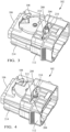
FIG. 2 shows an isometric view of a connector according to some embodiments. -
FIGs. 3 and 4 show the movement of the engaging lug within the first cam slot as the user moveable member moves relative to the connector housing according to some embodiments. -
FIG. 5 shows a top view of a subassembly of the connector according to some embodiments. -
FIG. 6 shows an isometric view of the subassembly ofFIG. 5 according to some embodiments. -
FIG. 7 illustrates a step of attaching a user moveable member to a connector housing of the connector ofFIG. 1 according to some embodiments according to some embodiments. -
FIG. 8 illustrates an alignment of an opening of a first cam slot in the user moveable member with an engaging lug on the cam member as the user moveable member is attached to the connector housing according to some embodiments. -
FIG. 9 shows a front view of the connector according to some embodiments. -
FIG. 10 shows a rear view of the connector according to some embodiments. -
FIG. 11 shows a locking barb that is configured to engage a catch on the connector housing according to some embodiments. -
FIG. 12 shows an isometric view of the corresponding mating connector according to some embodiments. -
FIG. 13 shows bottom view of a cam member of the connector according to some embodiments according to some embodiments. -
FIGs. 14 through 17 show a sequence of mating the connector with the corresponding mating connector according to some embodiments. -
FIGs. 18 through 21 show a sequence in attaching a cable strain relief device to wire cables extending from the connector according to some embodiments. -
FIG. 22 shows a flow chart of a method of operating a connector system according to some embodiments. -
FIG. 23 shows a flow chart of a method of assembling a connector system according to some embodiments. - In contrast to prior ergonomic axial mating assist devices, the electrical connector presented herein does not use a gear rack to rotate the cam member as was done in those prior ergonomic axial mating assist devices. Instead, pin and channel features engage the axial slider with the rotating mate assist cam. The channel shape may be contoured to optimize the ergonomic force feedback to the assembly operator mating the connector. This arrangement reduces the forward slider travel, compared to previous gear rack driven connector systems and enables the use of more compact short length device headers, which are desirable for space savings, especially in automotive vehicle packaging. This connector presented herein also includes several other features that provide low part cost and low cost assembly methods.
- A non-limiting example of a
connector system 100, in this example an electrical connector system, is shown inFIG. 1 . Theconnector system 100 includes afirst connector 102 and a corresponding matingsecond connector 104. Thefirst connector 102 includes aconnector housing 106 and acam member 108 which is rotatably attached to theconnector housing 106 by apivot 110. Thefirst connector 102 also includes a user moveable member, hereafter referred to as theslide 112, which is slidably attached to theconnector housing 106 and is sized and shaped to be mounted over theconnector housing 106 and to surround theconnector housing 106. Movement of theslide 112 along a longitudinal axis X (shown inFIG. 2 ) of theconnector housing 106 causes thecam member 108 to rotate around thepivot 110 which assists in mating and unmating the first andsecond connectors first connector 102 further includes a connector position assurance (CPA)device 114 that is configured to retain thefirst connector 102 to thesecond connector 104 once they are fully mated. Thefirst connector 102 also includes a cablestrain relief device 116 which is configured to snap over wire electrical cables 202 (seeFIG. 2 ) that are attached to electrical terminals (not shown) within theconnector housing 106 and a secondaryterminal locking feature 118 which inhibits primary terminal locking features 904 (seeFIGs. 9 and 10 ) from inadvertently releasing electrical terminals attached to the wireelectrical cables 202. - As illustrated in
FIG. 2 , thecam member 108 has anengaging lug 204 in the form of a post that extends along a vertical axis Z that is substantially parallel to an axis of rotation R of thecam member 108 around thepivot 110. Theslide 112 defines a curvedfirst cam slot 206 in which theengaging lug 204 defined by thecam member 108 is received. Thefirst cam slot 206 has a substantiallystraight entrance portion 208 that is generally parallel to the longitudinal axis X, acurved camming portion 210, and a substantiallystraight end portion 212 that is generally perpendicular to the longitudinal axis X. Additionally, theconnector housing 106 definesrails 214 that are received withinslots 216 in theslide 112. Therails 214 and theslots 216 are configured to cooperate with one another to cause theslide 112 to move relative to the connector housing in a substantially straight path along the X axis. -
FIGs. 3 and 4 show the movement of theengaging lug 204 within thefirst cam slot 206 as theslide 112 moves relative to theconnector housing 106. Thecam member 108 is rotated by movement of theengaging lug 204 through thefirst cam slot 206 as theslide 112 is moved longitudinally relative to theconnector housing 106. -
FIGs. 5 and 6 show top and isometric views respectively of theconnector housing 106 and thecam member 108 on thepivot 110 with theengaging lug 204 in a position to be received within thefirst cam slot 206. - As shown in
FIGs. 7 and 8 , theslide 112 is attached to theconnector housing 106 and theengaging lug 204 is aligned with and inserted into theentrance portion 208 of thefirst cam slot 206. In sone embodiments, theslide 112 defines astrap 702 bridging theentrance portion 208 of thefirst cam slot 206. Thestrap 702 generally increases the rigidity off theslide 112. -
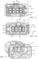
FIGs. 9 and 10 show front and rear views respectively of theconnector 102.Terminal cavities 902 are defined by theconnector housing 106 and hold the electrical terminals are shown inFIGs. 9 and 10 . Thesecond connector 104 further includes mating electrical terminals (not shown). Theterminal cavities 902 define primaryterminal locking features 904 that are configured to retain the electrical terminals in theterminal cavities 902. The secondaryterminal locking feature 118 is configured to inhibit flexing of the primaryterminal locking features 904 that could cause them to inadvertently release the electrical terminals. -
FIG. 11 shows alocking barb 1102 in theslide 112 that is configured to engage acatch 1002 on theconnector housing 106 previously shown inFIG. 10 . Thecatch 1002 is configured to engage thebarb 1102 in order to retain theslide 112 to theconnector housing 106. - As shown in
FIG. 12 , thesecond connector 104 defines acamming post 1202. - The
camming post 1202 is received within asecond cam slot 1302 in the underside of thecam member 108 shown inFIG. 13 . Thesecond cam slot 1302 has a substantiallystraight entrance portion 1304 and acurved camming portion 1306. As thecam member 108 is rotated by moving theslide 112 forward on theconnector housing 106, the camming post moves along thecurved camming portion 1306second cam slot 1302, thereby mating the first andsecond connector second connector cam member 108 in the opposite direction by moving theslide 112 rearward on theconnector housing 106. -
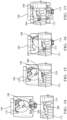
FIGs. 14 through 17 show a sequence of mating thefirst connector 102 with thesecond connector 104. - In
FIG. 14 , the first andsecond connectors lug 204 of thecam member 108 is disposed within theentrance portion 208 of thefirst cam slot 206 in theslide 112. Thesecond connector 104 is spaced apart from thefirst connector 102 and thecamming post 1202 of thesecond connector 104 is aligned with theentrance portion 1304 of thesecond cam slot 1302 in thecam member 108. - In
FIG. 15 , the first andsecond connectors slide 112 is at the beginning of its travel path and the engaginglug 204 of thecam member 108 remains within theentrance portion 208 of thefirst cam slot 206. Thecamming post 1202 is inserted within theentrance portion 1304 of thesecond cam slot 1302. - In
FIG. 16 , the first andsecond connectors slide 112 along the X axis causes the engaginglug 204 to move through theentrance portion 208, into thecurved camming portion 210, and toward theend portion 212 of thefirst cam slot 206. The movement of theslide 112 along the X axis also causes thecamming post 1202 to move through theentrance portion 1304 and into thecurved camming portion 1306 of thesecond cam slot 1302 on the other side of thecam member 108. The shape of thecurved camming portion 210 of thefirst cam slot 206 causes thecam member 108 to rotate around thepivot 110 as shown inFIG. 16 , thereby further causing thecamming post 1202 to move through thecurved camming portion 1306 and toward the end of the second cam slot. - In
FIG. 17 , the first andsecond connectors slide 112 is at the end of its travel path and the engaging lug of thecam member 108 is disposed in theend portion 212 of thefirst cam slot 206. Thecamming post 1202 of thesecond connector 104 is also disposed within the end of thesecond cam slot 1302 in thecam member 108. - The first and
second connectors slide 112 in the opposite direction shown inFIG. 16 . -
FIGs. 18 through 21 show a sequence of attaching the cablestrain relief device 116 over the wireelectrical cables 202. InFIG. 18 , thelatches 1802 of the cablestrain relief device 116 are detached, and the cablestrain relief device 116 is opened so that it may be placed over the wireelectrical cables 202. InFIG. 19 , the cablestrain relief device 116 is placed over the wireelectrical cables 202. InFIG 20 , the cablestrain relief device 116 is closed, and thelatches 1802 of the cablestrain relief device 116 are engaged to secure it to the wireelectrical cables 202. InFIG 21 , the cablestrain relief device 116 slides along the wireelectrical cables 202 and is disposed within a cavity 2002 (seeFIG. 20 ) in theconnector housing 106. - A
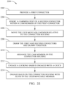
method 2200 of operating a connector system is shown inFIG 22 . Themethod 2200 includes the steps of: - At
STEP 2202, a first connector is provided. In some embodiments, this step includes providing afirst connector 102 having aconnector housing 106 and acam member 108 rotatably attached to theconnector housing 106. The cam member defines an engaginglug 204 extending along an axis Z substantially parallel to an axis of rotation R of thecam member 108, and a usermoveable member 112, e.g., a slide, slidably attached to theconnector housing 106. The usermoveable member 112 defines afirst cam slot 206 in which the engaginglug 204 is received. - At
STEP 2204, a camming post of a second connector is inserted within a cam member of the first connector. In some embodiments, this step includes inserting acamming post 1202 of asecond connector 104 within thecam member 108. - At
STEP 2206, the user moveable member is moved relative to the connector housing. In some embodiments, this step includes moving the usermoveable member 112 relative to theconnector housing 106, thereby rotating thecam member 108 by moving the engaginglug 204 along thefirst cam slot 206. - At
STEP 2208, the first and second connectors are drawn together. In some embodiments, this step includes drawing the first andsecond connectors camming post 1202 of the second connector along asecond cam slot 1302 defined by thecam member 108 due to the rotation of thecam member 108. - In some embodiments, the
first cam slot 206 may have anentrance portion 208 configured to receive the engaginglug 204, anend portion 212 arranged substantially perpendicularly to theentrance portion 208, and acurved camming portion 210 having one or more radii located between theentrance portion 208 and theend portion 212. In some embodiments, atSTEP 2210, the cam member is arranged on the connector housing. In some embodiments, this step includes arranging thecam member 108 on theconnector housing 106 such that the engaginglug 204 is in a position to be received within theentrance portion 208 of thefirst cam slot 206. - In some embodiments, at
STEP 2212, a locking barb is engaged with a catch. In some embodiments, this step includes engaging alocking barb 1102 which is defined by the usermoveable member 112 with acatch 1002 which is defined by theconnector housing 106, thereby retaining the usermoveable member 112 to theconnector housing 106. - In some embodiments, at
STEP 2214, rails on the connector housing engage with slots in the user moveable member. In some embodiments, this step includes engagingrails 214 defined by theconnector housing 106 that are inserted withinslots 216 in the usermoveable member 112 Therails 214 andslots 214 cooperate to cause the usermoveable member 112 and theconnector housing 106 to slide relative to each other in a substantially straight path along the X axis. - A
method 2300 of assembling a connector system is shown inFIG 23 . Themethod 2300 includes the steps of: - At
STEP 2302, a cam member is attached to a connector housing. In some embodiments, this step includes rotatably attaching acam member 108 defining anengaging lug 204 to aconnector housing 106. Thecam member 108 extends along an axis Z substantially parallel to an axis of rotation R of thecam member 108. - At
STEP 2304, a user moveable is attached to the connector housing. In some embodiments, this step includes slidably attaching a usermoveable member 112 defining afirst cam slot 206 to theconnector housing 106. - At
SETP 2306, the engaging lug is inserted within the first cam slot. In some embodiments, this step includes inserting the engaginglug 204 within thefirst cam slot 206. Thefirst cam slot 206 is shaped such that thecam member 108 is rotated by movement of the engaginglug 204 through thefirst cam slot 206 as the usermovable member 112 is moved longitudinally along the X axis relative to theconnector housing 106. - The
first cam slot 206 may have anentrance portion 208 configured to receive the engaginglug 204, anend portion 212 arranged substantially perpendicularly to theentrance portion 208, and acurved camming portion 210 having one or more radii located between theentrance portion 208 and theend portion 212. In some embodiments, atSTEP 2308, the cam member is arranged on the connector housing. In some embodiments, this step includes arranging thecam member 108 on theconnector housing 106 such that the engaginglug 204 is in a position to be received within theentrance portion 208 of thefirst cam slot 206. - In some embodiments, at
STEP 2310, a locking barb is engaged with a catch. In some embodiments, this step includes engaging alocking barb 1102 which is defined by the usermoveable member 112 with acatch 1002 which is defined by theconnector housing 106, thereby retaining the usermoveable member 112 to theconnector housing 106. - In some embodiments, at
STEP 2312, rails on the connector housing are engaged within slots in the user moveable member. in some embodiments, this step includes engagingrails 214 defined by theconnector housing 106 that are inserted withinslots 216 in the usermoveable member 112 Therails 214 andslots 214 cooperate to cause the usermoveable member 112 and theconnector housing 106 to slide relative to each other in a substantially straight path along the X axis. - The following are non-exclusive descriptions of possible embodiments of the present invention.
- In some aspects, the techniques described herein relate to a connector system, including: a connector having a connector housing; a cam member rotatably attached to the connector housing, wherein the cam member defines an engaging lug extending along an axis substantially parallel to an axis of rotation of the cam member; and a user moveable member slidably attached to the connector housing, wherein the user moveable member defines a first cam slot in which the engaging lug is received and wherein the first cam slot is shaped such that the cam member is rotated by movement of the engaging lug through the first cam slot as the user moveable member is moved longitudinally relative to the connector housing.
- The system of the preceding paragraph can optionally include, additionally and/or alternatively any, one or more of the following features, configurations and/or additional components.
- In some aspects, the techniques described herein relate to a connector system, wherein the connector is a first connector, wherein the connector system further includes a second connector configured to mate with the first connector, and wherein the cam member has a second cam slot configured to contact a camming post of the second connector and draw the first and second connectors together due to a rotation of the cam member.
- In some aspects, the techniques described herein relate to a connector system, wherein the first connector further includes electrical terminals disposed within cavities defined by the connector housing and wherein the second connector further includes mating electrical terminals.
- In some aspects, the techniques described herein relate to a connector system, wherein the cavities define primary locking features configured to retain the electrical terminals in the cavities and wherein the connector system further includes a secondary locking feature configured to inhibit the primary locking features from inadvertently releasing the electrical terminals.
- In some aspects, the techniques described herein relate to a connector system, further including a cable strain relief device configured to snap over wire electrical cables attached to the electrical terminals and be disposed within a retainer cavity in the connector housing.
- In some aspects, the techniques described herein relate to a connector system, wherein the second cam slot is curved along its length and wherein the camming post is a camming post defined by the second connector.
- In some aspects, the techniques described herein relate to a connector system, wherein the first cam slot has a substantially straight entrance portion configured to receive the engaging lug, a substantially straight end portion arranged substantially perpendicularly to the entrance portion, and a curved camming portion having one or more radii located between the entrance portion and the end portion.
- In some aspects, the techniques described herein relate to a connector system, wherein the cam member may be arranged on the connector housing such that the engaging lug is in a position to be received within the entrance portion of the first cam slot.
- In some aspects, the techniques described herein relate to a connector system, wherein the user moveable member defines a strap bridging the entrance portion of the first cam slot.
- In some aspects, the techniques described herein relate to a connector system, wherein the user moveable member defines a locking barb which is configured to engage a catch which is defined by the connector housing, thereby retaining the user moveable member to the connector housing.
- In some aspects, the techniques described herein relate to a connector system, wherein the connector housing defines rails that are received within slots in the user moveable member which are configured to cooperate to cause the user moveable member and the connector housing to slide relative to each other in a substantially straight path.
- In some aspects, the techniques described herein relate to a method of operating a connector system, including: providing a first connector having a connector housing and a cam member rotatably attached to the connector housing, wherein the cam member defines an engaging lug extending along an axis substantially parallel to an axis of rotation of the cam member, and a user moveable member slidably attached to the connector housing, wherein the user moveable member defines a first cam slot in which the engaging lug is received; inserting a camming post of a second connector within the cam member; moving the user moveable member relative to the connector housing, thereby rotating the cam member by moving the engaging lug along the first cam slot; and drawing the first and second connectors together by movement of a camming post of the second connector along a second cam slot defined by the cam member due to the rotation of the cam member.
- The method of the preceding paragraph can optionally include, additionally and/or alternatively any, one or more of the following features, configurations and/or additional components.
- In some aspects, the techniques described herein relate to a method, wherein the first cam slot has a substantially straight entrance portion configured to receive the engaging lug, a substantially straight end portion arranged substantially perpendicularly to the entrance portion, and a curved camming portion having one or more radii located between the entrance portion and the end portion and wherein the method further includes arranging the cam member on the connector housing such that the engaging lug is in a position to be received within the entrance portion of the first cam slot.
- In some aspects, the techniques described herein relate to a method, wherein the method further includes engaging a locking barb which is defined by the user moveable member with a catch which is defined by the connector housing, thereby retaining the user moveable member to the connector housing.
- In some aspects, the techniques described herein relate to a method, wherein the second cam slot is curved along its length and wherein the camming post is a camming post defined by the second connector.
- In some aspects, the techniques described herein relate to a method, wherein the method further includes engaging rails defined by the connector housing within slots in the user moveable member which are configured to cooperate to cause the user moveable member and the connector housing to slide relative to each other in a substantially straight path.
- In some aspects, the techniques described herein relate to a method of assembling a connector system, including: rotatably attaching a cam member defining an engaging lug to a connector housing, wherein the engaging post extends along an axis substantially parallel to an axis of rotation of the cam member; slidably attaching a user moveable member defining a first cam slot to the connector housing; and inserting the engaging lug within the first cam slot, wherein the first cam slot is shaped such that the cam member is rotated by movement of the engaging lug through the first cam slot as the user moveable member is moved longitudinally relative to the connector housing.
- The method of the preceding paragraph can optionally include, additionally and/or alternatively any, one or more of the following features, configurations and/or additional components.
- In some aspects, the techniques described herein relate to a method, wherein the first cam slot has a substantially straight entrance portion configured to receive the engaging lug, a substantially straight end portion arranged substantially perpendicularly to the entrance portion, and a curved camming portion having one or more radii located between the entrance portion and the end portion and wherein the method further includes arranging the cam member on the connector housing such that the engaging lug is in a position to be received within the entrance portion of the first cam slot.
- In some aspects, the techniques described herein relate to a method, wherein the method further includes engaging a locking barb which is defined by the user moveable member with a catch which is defined by the connector housing, thereby retaining the user moveable member to the connector housing.
- In some aspects, the techniques described herein relate to a method, wherein the method further includes engaging rails defined by the connector housing within slots in the user moveable member which are configured to cooperate to cause the user moveable member and the connector housing to slide relative to each other in a substantially straight path.
- While the invention has been described with reference to an exemplary embodiment(s), it will be understood by those skilled in the art that various changes may be made, and equivalents may be substituted for elements thereof without departing from the scope of the invention. In addition, many modifications may be made to adapt a particular situation or material to the teachings of the invention without departing from the essential scope thereof. Therefore, it is intended that the invention is not limited to the disclosed embodiment(s), but that the invention will include all embodiments falling within the scope of the appended claims.
- As used herein, 'one or more' includes a function being performed by one element, a function being performed by more than one element, e.g., in a distributed fashion, several functions being performed by one element, several functions being performed by several elements, or any combination of the above.
- It will also be understood that, although the terms first, second, etc. are, in some instances, used herein to describe various elements, these elements should not be limited by these terms. These terms are only used to distinguish one element from another. For example, a first contact could be termed a second contact, and, similarly, a second contact could be termed a first contact, without departing from the scope of the various described embodiments. The first contact and the second contact are both contacts, but they are not the same contact.
- The terminology used in the description of the various described embodiments herein is for the purpose of describing particular embodiments only and is not intended to be limiting. As used in the description of the various described embodiments and the appended claims, the singular forms "a", "an" and "the" are intended to include the plural forms as well, unless the context clearly indicates otherwise. It will also be understood that the term "and/or" as used herein refers to and encompasses any and all possible combinations of one or more of the associated listed items. It will be further understood that the terms "includes," "including," "comprises," and/or "comprising," when used in this specification, specify the presence of stated features, integers, steps, operations, elements, and/or components, but do not preclude the presence or addition of one or more other features, integers, steps, operations, elements, components, and/or groups thereof.
- As used herein, the term "if' is, optionally, construed to mean "when" or "upon" or "in response to determining" or "in response to detecting," depending on the context. Similarly, the phrase "if it is determined" or "if [a stated condition or event] is detected" is, optionally, construed to mean "upon determining" or "in response to determining" or "upon detecting [the stated condition or event]" or "in response to detecting [the stated condition or event]," depending on the context.
- Additionally, while terms of ordinance or orientation may be used herein these elements should not be limited by these terms. All terms of ordinance or orientation, unless stated otherwise, are used for purposes distinguishing one element from another, and do not denote any particular order, order of operations, direction or orientation unless stated otherwise.
Claims (15)
- A connector system (100), comprising:a connector (102) having a connector housing (106);a cam member (108) rotatably attached to the connector housing (106), wherein the cam member (108) defines an engaging lug (204) extending along an axis substantially parallel to an axis of rotation of the cam member (108); anda user moveable member (112) slidably attached to the connector housing (106), wherein the user moveable member (112) defines a first cam slot (206) in which the engaging lug (204) is received and wherein the first cam slot (206) is shaped such that the cam member (108) is rotated by movement of the engaging lug (204) through the first cam slot (206) as the user moveable member (112) is moved longitudinally relative to the connector housing (106).
- The connector system (100) according to claim 1, wherein the connector (102) is a first connector (102), wherein the connector system (100) further comprises a second connector (104) configured to mate with the first connector (102), and wherein the cam member (108) has a second cam slot (1302) configured to contact a camming post (1202) of the second connector (104) and draw the first and second connectors (102, 104) together due to a rotation of the cam member (108).
- The connector system (100) according to claim 2, wherein the first connector (102) further comprises electrical terminals disposed within cavities defined by the connector housing (106) and wherein the second connector (104) further comprises mating electrical terminals.
- The connector system (100) according to claim 3, wherein the cavities define primary locking features configured to retain the electrical terminals in the cavities and wherein the connector system (100) further comprises a secondary locking feature configured to inhibit the primary locking features from inadvertently releasing the electrical terminals.
- The connector system (100) according to claim 3 or 4, further comprising a cable strain relief device (116) configured to snap over wire electrical cables (202) attached to the electrical terminals and be disposed within a retainer cavity (2002) in the connector housing (106).
- The connector system (100) according to any one of the preceding claims, wherein the first cam slot (206) has a substantially straight entrance portion (208) configured to receive the engaging lug (204), a substantially straight end portion (212) arranged substantially perpendicularly to the entrance portion (208), and a curved camming portion (210) having one or more radii located between the entrance portion (208) and the end portion (212).
- The connector system (100) according to claim 6, wherein the cam member (108) may be arranged on the connector housing (106) such that the engaging lug (204) is in a position to be received within the entrance portion (208) of the first cam slot (206).
- The connector system (100) according to any one of the preceding claims, wherein the user moveable member (112) defines a locking barb (1102) which is configured to engage a catch (1002) which is defined by the connector housing (106), thereby retaining the user moveable member (112) to the connector housing (106).
- The connector system (100) according to any one of the preceding claims, wherein the connector housing (106) defines rails (214) that are received within slots (216) in the user moveable member (112) which are configured to cooperate to cause the user moveable member (112) and the connector housing (106) to slide relative to each other in a substantially straight path.
- A method (2200) of operating a connector system (100), comprising:providing a first connector (102) having a connector housing (106) and a cam member (108) rotatably attached to the connector housing (106), wherein the cam member (108) defines an engaging lug (204) extending along an axis substantially parallel to an axis of rotation of the cam member (108), and a user moveable member (112) slidably attached to the connector housing (106), wherein the user moveable member (112) defines a first cam slot (206) in which the engaging lug (204) is received;inserting a camming post (1202) of a second connector (104) within the cam member (108);moving the user moveable member (112) relative to the connector housing (106), thereby rotating the cam member (108) by moving the engaging lug (204) along the first cam slot (206); anddrawing the first and second connectors (102, 104) together by movement of a camming post (1202) of the second connector (104) along a second cam slot (1302) defined by the cam member (108) due to the rotation of the cam member (108).
- The method (2200) according to claim 10, wherein the first cam slot (206) has a substantially straight entrance portion (208) configured to receive the engaging lug (204), a substantially straight end portion (212) arranged substantially perpendicularly to the entrance portion (208), and a curved camming portion (210) having one or more radii located between the entrance portion (208) and the end portion (212) and wherein the method (2200) further comprises arranging the cam member (108) on the connector housing (106) such that the engaging lug (204) is in a position to be received within the entrance portion (208) of the first cam slot (206).
- The method (2200) according to claim 10 or 11, wherein the method (2200) further comprises engaging a locking barb (1102) which is defined by the user moveable member (112) with a catch (1002) which is defined by the connector housing (106), thereby retaining the user moveable member (112) to the connector housing (106).
- The method (2200) according to any one of claims 10 to 12, wherein the method (2200) further comprises engaging rails (214) defined by the connector housing (106) within slots (216) in the user moveable member (112) which are configured to cooperate to cause the user moveable member (112) and the connector housing (106) to slide relative to each other in a substantially straight path.
- A method (2300) of assembling a connector system (100), comprising:rotatably attaching a cam member (108) defining an engaging lug (204) to a connector housing (106), wherein the engaging lug (204) extends along an axis substantially parallel to an axis of rotation of the cam member (108);slidably attaching a user moveable member (112) defining a first cam slot (206) to the connector housing (106); andinserting the engaging lug (204) within the first cam slot (206), wherein the first cam slot (206) is shaped such that the cam member (108) is rotated by movement of the engaging lug (204) through the first cam slot (206) as the user moveable member (112) is moved longitudinally relative to the connector housing (106).
- The method (2300) according to claim 14, wherein the first cam slot (206) has a substantially straight entrance portion (208) configured to receive the engaging lug (204), a substantially straight end portion (212) arranged substantially perpendicularly to the entrance portion (208), and a curved camming portion (210) having one or more radii located between the entrance portion (208) and the end portion (212) and wherein the method (2300) further comprises arranging the cam member (108) on the connector housing (106) such that the engaging lug (204) is in a position to be received within the entrance portion (208) of the first cam slot (206).
Applications Claiming Priority (3)
| Application Number | Priority Date | Filing Date | Title |
|---|---|---|---|
| US202363450467P | 2023-03-07 | 2023-03-07 | |
| US202363458713P | 2023-04-12 | 2023-04-12 | |
| US18/597,089 US20240305042A1 (en) | 2023-03-07 | 2024-03-06 | Electrical connector with ergonomic axial mating assist device |
Publications (1)
| Publication Number | Publication Date |
|---|---|
| EP4429041A1 true EP4429041A1 (en) | 2024-09-11 |
Family
ID=90230790
Family Applications (1)
| Application Number | Title | Priority Date | Filing Date |
|---|---|---|---|
| EP24162004.6A Pending EP4429041A1 (en) | 2023-03-07 | 2024-03-07 | Electrical connector with ergonomic axial mating assist device |
Country Status (2)
| Country | Link |
|---|---|
| US (1) | US20240305042A1 (en) |
| EP (1) | EP4429041A1 (en) |
Families Citing this family (1)
| Publication number | Priority date | Publication date | Assignee | Title |
|---|---|---|---|---|
| JP2021128865A (en) * | 2020-02-14 | 2021-09-02 | 住友電装株式会社 | Lever type connector |
Citations (9)
| Publication number | Priority date | Publication date | Assignee | Title |
|---|---|---|---|---|
| US6186827B1 (en) * | 1999-05-31 | 2001-02-13 | Yazaki Corporation | Connector supporting mechanism |
| EP0793304B1 (en) * | 1996-02-27 | 2004-04-28 | Autonetworks Technologies, Ltd. | Connector connection structure |
| US7462047B2 (en) | 2005-07-28 | 2008-12-09 | Fci Americas Technology, Inc. | Electrical connector assembly with connection assist |
| US7744390B2 (en) | 2005-07-28 | 2010-06-29 | Fci Americas Technology, Inc. | Electrical connector assembly with connection assist |
| US8192212B2 (en) | 2008-08-04 | 2012-06-05 | Fci Automotive Holding | Electrical connector system with temporarily blocking during unmating of two connectors |
| JP5884711B2 (en) * | 2012-11-14 | 2016-03-15 | 住友電装株式会社 | Lever type connector |
| US9912101B1 (en) | 2017-02-08 | 2018-03-06 | Delphi Technologies, Inc | Electrical connector assembly with axial connection assist |
| US9917402B1 (en) | 2017-06-02 | 2018-03-13 | Delphi Technologies, Inc. | Connector assembly with variable axial assist |
| US10290970B1 (en) | 2018-02-08 | 2019-05-14 | Delphi Technologies, Llc | Connector with strain relief device |
Family Cites Families (3)
| Publication number | Priority date | Publication date | Assignee | Title |
|---|---|---|---|---|
| US6612854B2 (en) * | 2000-08-11 | 2003-09-02 | Autonetworks Technologies, Ltd. | Slider-equipped connector and connector |
| US6565372B2 (en) * | 2001-02-27 | 2003-05-20 | Delphi Technologies, Inc. | Staged lock feature for an electrical connector assembly having a cam mating device |
| US20240380161A1 (en) * | 2023-05-11 | 2024-11-14 | Aptiv Technologies AG | Electrical connector with ergonomic axial mating assist device |
-
2024
- 2024-03-06 US US18/597,089 patent/US20240305042A1/en active Pending
- 2024-03-07 EP EP24162004.6A patent/EP4429041A1/en active Pending
Patent Citations (9)
| Publication number | Priority date | Publication date | Assignee | Title |
|---|---|---|---|---|
| EP0793304B1 (en) * | 1996-02-27 | 2004-04-28 | Autonetworks Technologies, Ltd. | Connector connection structure |
| US6186827B1 (en) * | 1999-05-31 | 2001-02-13 | Yazaki Corporation | Connector supporting mechanism |
| US7462047B2 (en) | 2005-07-28 | 2008-12-09 | Fci Americas Technology, Inc. | Electrical connector assembly with connection assist |
| US7744390B2 (en) | 2005-07-28 | 2010-06-29 | Fci Americas Technology, Inc. | Electrical connector assembly with connection assist |
| US8192212B2 (en) | 2008-08-04 | 2012-06-05 | Fci Automotive Holding | Electrical connector system with temporarily blocking during unmating of two connectors |
| JP5884711B2 (en) * | 2012-11-14 | 2016-03-15 | 住友電装株式会社 | Lever type connector |
| US9912101B1 (en) | 2017-02-08 | 2018-03-06 | Delphi Technologies, Inc | Electrical connector assembly with axial connection assist |
| US9917402B1 (en) | 2017-06-02 | 2018-03-13 | Delphi Technologies, Inc. | Connector assembly with variable axial assist |
| US10290970B1 (en) | 2018-02-08 | 2019-05-14 | Delphi Technologies, Llc | Connector with strain relief device |
Also Published As
| Publication number | Publication date |
|---|---|
| US20240305042A1 (en) | 2024-09-12 |
Similar Documents
| Publication | Publication Date | Title |
|---|---|---|
| EP3823106B1 (en) | Electrical connector assembly with connection assist | |
| US10038278B2 (en) | Electrical connector having a connector position assurance element | |
| EP1978606B1 (en) | Slide lock panel-mount connector | |
| US6120308A (en) | Electrical connector assembly which can be rotatably connected and disconnected | |
| EP1548892A1 (en) | Electrical connector | |
| US5618201A (en) | Connector having engagement detecting device | |
| EP0572012A1 (en) | Body-mounted connector | |
| EP3593416B1 (en) | Connector assembly | |
| US5664960A (en) | Power feed connector | |
| US8241052B2 (en) | Electrical connector system with power and command connectors | |
| GB2342791A (en) | Connector preventing half-fitting, having trapezoidal abutment | |
| CN109698427B (en) | Electric connector with auxiliary handle | |
| EP0793304A2 (en) | Connector connection structure | |
| US10340618B1 (en) | Electrical terminal housing with releasable terminal locks | |
| CN109698436B (en) | Electric connector with auxiliary handle | |
| EP3979427B1 (en) | Primary locks with terminal serviceablity features for mixed connection coaxial cables | |
| US20240305042A1 (en) | Electrical connector with ergonomic axial mating assist device | |
| EP1231678B1 (en) | Latch and release mechanism for an electrical connector | |
| EP4462611A1 (en) | Electrical connector with ergonomic axial mating assist device | |
| US7553179B2 (en) | Connector latch retainer | |
| EP2804268B1 (en) | Lever-type connector | |
| EP3734770B1 (en) | Electrical connector having position holder | |
| US6343944B1 (en) | Connector supporting mechanism | |
| US10950967B2 (en) | Electric terminal housing with a terminal lock | |
| US6276948B1 (en) | Connector supporting mechanism |
Legal Events
| Date | Code | Title | Description |
|---|---|---|---|
| PUAI | Public reference made under article 153(3) epc to a published international application that has entered the european phase |
Free format text: ORIGINAL CODE: 0009012 |
|
| STAA | Information on the status of an ep patent application or granted ep patent |
Free format text: STATUS: THE APPLICATION HAS BEEN PUBLISHED |
|
| AK | Designated contracting states |
Kind code of ref document: A1 Designated state(s): AL AT BE BG CH CY CZ DE DK EE ES FI FR GB GR HR HU IE IS IT LI LT LU LV MC ME MK MT NL NO PL PT RO RS SE SI SK SM TR |
|
| RAP3 | Party data changed (applicant data changed or rights of an application transferred) |
Owner name: APTIV TECHNOLOGIES AG |
|
| STAA | Information on the status of an ep patent application or granted ep patent |
Free format text: STATUS: REQUEST FOR EXAMINATION WAS MADE |
|
| 17P | Request for examination filed |
Effective date: 20250311 |
|
| GRAP | Despatch of communication of intention to grant a patent |
Free format text: ORIGINAL CODE: EPIDOSNIGR1 |
|
| STAA | Information on the status of an ep patent application or granted ep patent |
Free format text: STATUS: GRANT OF PATENT IS INTENDED |
|
| RIC1 | Information provided on ipc code assigned before grant |
Ipc: H01R 13/629 20060101AFI20260310BHEP Ipc: H01R 13/639 20060101ALN20260310BHEP Ipc: H01R 13/52 20060101ALN20260310BHEP |
|
| RIC1 | Information provided on ipc code assigned before grant |
Ipc: H01R 13/629 20060101AFI20260326BHEP Ipc: H01R 13/639 20060101ALN20260326BHEP Ipc: H01R 13/52 20060101ALN20260326BHEP |
|
| INTG | Intention to grant announced |
Effective date: 20260409 |