EP4429019A1 - Clamping apparatus for antenna device - Google Patents
Clamping apparatus for antenna device Download PDFInfo
- Publication number
- EP4429019A1 EP4429019A1 EP22890274.8A EP22890274A EP4429019A1 EP 4429019 A1 EP4429019 A1 EP 4429019A1 EP 22890274 A EP22890274 A EP 22890274A EP 4429019 A1 EP4429019 A1 EP 4429019A1
- Authority
- EP
- European Patent Office
- Prior art keywords
- tilting
- mounting bracket
- drive unit
- steering
- coupled
- Prior art date
- Legal status (The legal status is an assumption and is not a legal conclusion. Google has not performed a legal analysis and makes no representation as to the accuracy of the status listed.)
- Pending
Links
Images




Classifications
-
- H—ELECTRICITY
- H01—ELECTRIC ELEMENTS
- H01Q—ANTENNAS, i.e. RADIO AERIALS
- H01Q1/00—Details of, or arrangements associated with, antennas
- H01Q1/12—Supports; Mounting means
-
- H—ELECTRICITY
- H01—ELECTRIC ELEMENTS
- H01Q—ANTENNAS, i.e. RADIO AERIALS
- H01Q1/00—Details of, or arrangements associated with, antennas
- H01Q1/12—Supports; Mounting means
- H01Q1/125—Means for positioning
- H01Q1/1264—Adjusting different parts or elements of an aerial unit
-
- H—ELECTRICITY
- H01—ELECTRIC ELEMENTS
- H01Q—ANTENNAS, i.e. RADIO AERIALS
- H01Q1/00—Details of, or arrangements associated with, antennas
- H01Q1/12—Supports; Mounting means
- H01Q1/1207—Supports; Mounting means for fastening a rigid aerial element
- H01Q1/1228—Supports; Mounting means for fastening a rigid aerial element on a boom
-
- H—ELECTRICITY
- H01—ELECTRIC ELEMENTS
- H01Q—ANTENNAS, i.e. RADIO AERIALS
- H01Q1/00—Details of, or arrangements associated with, antennas
- H01Q1/12—Supports; Mounting means
- H01Q1/125—Means for positioning
-
- H—ELECTRICITY
- H01—ELECTRIC ELEMENTS
- H01Q—ANTENNAS, i.e. RADIO AERIALS
- H01Q1/00—Details of, or arrangements associated with, antennas
- H01Q1/12—Supports; Mounting means
- H01Q1/22—Supports; Mounting means by structural association with other equipment or articles
- H01Q1/24—Supports; Mounting means by structural association with other equipment or articles with receiving set
- H01Q1/241—Supports; Mounting means by structural association with other equipment or articles with receiving set used in mobile communications, e.g. GSM
- H01Q1/246—Supports; Mounting means by structural association with other equipment or articles with receiving set used in mobile communications, e.g. GSM specially adapted for base stations
-
- H—ELECTRICITY
- H01—ELECTRIC ELEMENTS
- H01Q—ANTENNAS, i.e. RADIO AERIALS
- H01Q3/00—Arrangements for changing or varying the orientation or the shape of the directional pattern of the waves radiated from an antenna or antenna system
- H01Q3/02—Arrangements for changing or varying the orientation or the shape of the directional pattern of the waves radiated from an antenna or antenna system using mechanical movement of antenna or antenna system as a whole
- H01Q3/08—Arrangements for changing or varying the orientation or the shape of the directional pattern of the waves radiated from an antenna or antenna system using mechanical movement of antenna or antenna system as a whole for varying two co-ordinates of the orientation
Definitions
- the present invention relates to a clamping apparatus for an antenna device, and more particularly, to a clamping apparatus for an antenna device, which is capable of efficiently disposing an antenna device in a dense installation space and easily adjusting a direction of the antenna device.
- a multiple-input/multiple-output (MIMO) technology refers to a technology for innovatively increasing data transmission capacity by using a plurality of antennas.
- This technology uses a spatial multiplexing technique, in which a transmitter transmits different data through the respective transmission antennas, and a receiver distinguishes the transmitted data by performing appropriate signal processing.
- Eight antennas are used in 4G LTE-advanced, and a product equipped with 64 or 128 antennas has been developed in a current pre-5G step. It is expected that base station equipment having a much larger number of antennas will be used in 5G, which refers to a massive MIMO technology.
- the current cell management is 2-dimension, whereas 3D-beam forming is enabled when the massive MIMO technology is introduced, which also represents a full-dimension (FD) MIMO.
- the number of transmitters and the number of filters are increased as the number of antennas (ANTs) is increased.
- RF components (antennas, filters, power amplifiers, transceivers, etc.) need to be practically manufactured to be small in size, light in weight, and inexpensive, and the massive MIMO requires a high output to expand a coverage.
- electric power consumption and heat generation which are caused by the high output, have a negative effect on reductions in weight and size.
- Korean Patent No. 10-2095871 (published on April 2, 2020 ) (hereinafter, referred to as 'the related art') discloses a 'clamping apparatus for an antenna' including a tilting unit configured to rotate an antenna device in an upward/downward direction, and a steering unit configured to rotate the antenna device in a leftward/rightward direction.
- An object of the present invention is to provide a clamping apparatus for an antenna device, which is capable of rotating an antenna in an upward/downward direction and a horizontal direction and ensuring a maximum range in which the antenna is rotated in the upward/downward direction.
- the present invention provides a clamping apparatus for an antenna device, the clamping apparatus including: an antenna mounting bracket coupled to a rear surface of an antenna device and configured to support the antenna device; a steering drive unit coupled to be rotatable in a horizontal direction relative to a support pole mounting bracket installed on a support pole; a tilting drive unit movably coupled to the steering drive unit; and at least one tilting link member configured to rotate the tilting drive unit relative to the steering drive unit and move the antenna mounting bracket relative to the tilting drive unit during tilting and steering operations.
- the support pole mounting bracket may include: an upper support pole mounting bracket installed on the support pole and configured such that the steering drive unit is horizontally rotatably coupled to the upper support pole mounting bracket; and a lower support pole mounting bracket installed on the support pole so as to be disposed below the upper support pole mounting bracket and configured to support a lower portion of the antenna mounting bracket so that the lower portion of the antenna mounting bracket is rotatable in an upward/downward direction and rotatable in the horizontal direction.
- the lower support pole mounting bracket may include: a lower support pole mounting main body; a lower steering part coupled to the lower support pole mounting main body so as to be rotatable in the horizontal direction; and a lower tilting part coupled to the lower steering part so as to be rotatable in the upward/downward direction and coupled to the lower portion of the antenna mounting bracket.
- the at least one tilting link member may include: a first tilting link member having one end coupled to an upper portion of the antenna mounting bracket, and the other end rotatably coupled to the tilting drive unit, the first tilting link member being configured to rotate the antenna mounting bracket in an upward/downward direction by driving power of the tilting drive unit; and a second tilting link member having one end coupled to the tilting drive unit, and the other end rotatably coupled to the steering drive unit, the second tilting link member being configured to allow the tilting drive unit to be rotatable in the upward/downward direction relative to the steering drive unit.
- first tilting link member may be hingedly connected to the upper portion of the antenna mounting bracket so as to be rotatable relative to the upper portion of the antenna mounting bracket, and the other end of the first tilting link member may be coupled and connected to a tilting rotary shaft of the tilting drive unit to rotate one end thereof by receiving driving power from the tilting drive unit.
- one end of the second tilting link member may be fixed to operate in conjunction with the tilting drive unit when the antenna mounting bracket is rotated in the upward/downward direction by the first tilting link member, and the other end of the second tilting link member may be hingedly connected to the steering drive unit so as to be rotatable relative to the steering drive unit.
- the tilting drive unit may include: a tilting housing; a tilting speed reducer disposed in the tilting housing and having a tilting worm gear; and a tilting rotary shaft disposed in the tilting housing and having an outer peripheral surface on which a tilting worm wheel gear, which engages with the tilting worm gear, is provided, the tilting rotary shaft being disposed horizontally and coupled to the other end of the first tilting link member.
- a tilting shaft matching part having a concave-convex shape may be provided at an outer end of the tilting rotary shaft
- a link matching part, which is matched with the tilting shaft matching part may be provided at the other end of the first tilting link member, and the other end of the first tilting link member may be coupled by means of a link fastening bolt in a state in which the link matching part is matched with the tilting shaft matching part.
- the antenna mounting bracket may include: an antenna mounting bracket body coupled to a rear surface of the antenna device; and an antenna mounting bracket wing protruding from the antenna mounting bracket body toward the support pole and hingedly coupled to one end of the first tilting link member by means of a fixing member.
- the fixing member may be provided as a hinge bearing type configured to support a rotation between one end of the first tilting link member and the antenna mounting bracket wing.
- the antenna mounting bracket wing may be provided as a pair of antenna mounting bracket wings spaced apart from each other in the horizontal direction
- the first tilting link member may be provided as a pair of first tilting link members each having one end coupled to each of the pair of antenna mounting bracket wings
- the pair of first tilting link members may have the other ends rotatably and hingedly coupled to two opposite left and right sides of the tilting drive unit, respectively.
- the second tilting link member may be provided as a pair of second tilting link members each having one end coupled to each of two opposite sides of the tilting drive unit, and the pair of second tilting link members may have the other ends rotatably and hingedly coupled to two opposite left and right sides of the steering drive unit, respectively.
- the other end of the second tilting link member may be coupled to the steering drive unit by means of a roller bearing.
- the steering drive unit may include: a steering housing; a steering speed reducer disposed in the steering housing and having a steering worm gear; and a steering rotary shaft disposed in the steering housing and having an outer peripheral surface on which a steering worm wheel gear, which engages with the steering worm gear, is provided, the steering rotary shaft being disposed vertically and coupled to the upper support pole mounting bracket.
- a rotary shaft of the steering worm gear may be horizontally disposed to be inclined leftward or rightward in the steering housing.
- the clamping apparatus for an antenna device may ensure a maximum tilting adjustment range of the antenna device by means of the first tilting link members and the second tilting link members.
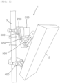
- FIG. 1 is a perspective view illustrating a state in which an antenna device is tilted in a state in which the antenna device is installed on a support pole
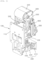
- FIG. 2 is a front perspective view illustrating a clamping apparatus for an antenna device illustrated in FIG. 1
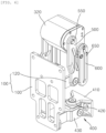
- FIG. 3 is a rear perspective view illustrating the clamping apparatus for an antenna device illustrated in FIG. 1 .
- the clamping apparatus of the present invention is applied to an antenna device.
- the clamping apparatus of the present invention may be applied not only to a case in which the antenna device is installed on the support pole but also to a case in which a lighting device (not illustrated), such as an LED lighting device or a high-output sport lighting, is installed on a support pole.
- a clamping apparatus 1 for an antenna device may be an apparatus for installing an antenna device 2 on a support pole 3.
- the clamping apparatus 1 for an antenna device may adjust a direction of the antenna device 2 by rotating the antenna device 2 in an upward/downward direction and a leftward/rightward direction.
- the antenna device 2 may include an approximately hexahedral antenna housing (no reference numeral).
- a printed circuit board, on which at least one antenna element and at least one radio signal processing part (radio unit (RU)) are mounted, may be provided in the antenna housing.
- radio unit radio unit
- the antenna element may transmit or receive radio signals
- the radio signal processing part may process the radio signals.
- the antenna housing may, of course, be made of a heat dissipation material such as aluminum. Heat dissipation ribs may be formed on an outer surface of the antenna housing to increase contact areas with ambient air.
- the support pole 3 may be configured as an RC bar. Of course, the support pole 3 is not limited to the RC bar. Examples of the support pole 3 may include all column-shaped members having outer peripheral surfaces on which the antenna device 2 is installed by means of the clamping apparatus 1 for an antenna.
- the clamping apparatus 1 for an antenna device may include an antenna mounting bracket 100, support pole mounting brackets 200 and 400, a tilting drive unit 320, a steering drive unit 330, and one or more tilting link members 500 and 600.
- the antenna mounting bracket 100 may be mounted on a rear surface of the antenna device 2 and support the antenna device 2.
- the support pole mounting brackets 200 and 400 include an upper support pole mounting bracket 200 and a lower support pole mounting bracket 400.
- the upper support pole mounting bracket 200 and the lower support pole mounting bracket 400 may be disposed on a straight line and spaced apart from each other in a longitudinal direction of the support pole 3.
- the upper support pole mounting bracket 200 may be installed on the support pole 3 and disposed relatively above the lower support pole mounting bracket 400.
- the upper support pole mounting bracket 200 may be coupled to a rear portion of the steering drive unit 330, and the steering drive unit 330 may be supported on the upper support pole mounting bracket 200 so as to be rotatable in a horizontal direction.
- the lower support pole mounting bracket 400 may be disposed relatively below the upper support pole mounting bracket 200 and installed on the support pole 3.
- the lower support pole mounting bracket 400 may support a lower portion of the antenna mounting bracket 100 so that the lower portion of the antenna mounting bracket 100 is rotatable in the upward/downward direction and the horizontal direction.
- FIG. 4 is an exploded perspective view illustrating the clamping apparatus for an antenna device illustrated in FIG. 2
- FIG. 5 is an exploded perspective view illustrating the clamping apparatus for an antenna device illustrated in FIG. 3
- FIG. 6 is a perspective view of a tilting drive unit in a state in which the steering drive unit illustrated in FIG. 4 is excluded
- FIG. 7A is an exploded perspective view when FIG. 6 is viewed in one direction, i.e., an exploded perspective view illustrating a state in which the tilting link member is separated
- FIG. 7B is an exploded perspective view illustrating a front side in FIG. 6 , i.e., an exploded perspective view illustrating a state in which an internal configuration is exposed
- FIG. 8A is an exploded perspective view when FIG.
- FIG. 6 is viewed in the other direction, i.e., an exploded perspective view illustrating a state in which the tilting link member is separated
- FIG. 8B is an exploded perspective view illustrating a rear side in FIG. 6 , i.e., an exploded perspective view illustrating a state in which the internal configuration is exposed
- FIG. 9 is a cut-away perspective view illustrating an interior of the tilting drive unit.
- the tilting drive unit 320 may generate driving power for tilting the antenna device 2 in the upward/downward direction.
- the tilting drive unit 320 may be coupled to the upper support pole mounting bracket 200 so as to be rotatable in the horizontal direction and installed to move integrally with the steering drive unit 330 that is rotated in the horizontal direction by the driving power of the tilting drive unit 320.
- one or more tilting link members 500 and 600 may include first tilting link members 500 substantially related to the tilting operation of the antenna device 2, and second tilting link members 600 configured to connect the tilting drive unit 320 and the steering drive unit 330.
- One end of the first tilting link member 500 may be coupled to an upper portion of the antenna mounting bracket 100, and the other end of the first tilting link member 500 may be rotatably coupled to the tilting drive unit 320, such that the first tilting link member 500 may rotate the antenna mounting bracket 100 in the upward/downward direction by means of the driving power of the tilting drive unit 320.
- first tilting link member 500 may be hingedly connected to the upper portion of the antenna mounting bracket 100 so as to be rotatable relative to the upper portion of the antenna mounting bracket 100, and the other end of the first tilting link member 500 may be coupled and connected to a tilting rotary shaft 326 of the tilting drive unit 320, such that the first tilting link member 500 may rotate one end of the tilting drive unit 320 by receiving the driving power from the tilting drive unit 320.
- a tilting shaft matching part 326-1 having a concave-convex shape may be provided at an outer end of the tilting rotary shaft 326, and a link matching part 500-1 may be provided at the other end of the first tilting link member 500 and matched with the tilting shaft matching part 326-1.
- the link matching part 500-1 comes into surface contact and is matched with the tilting shaft matching part 326-1, the link matching part 500-1 interferes with the tilting shaft matching part 326-1 in a rotation direction of the first tilting link member 500, such that the first tilting link member 500 may receive a rotational force of the tilting rotary shaft 326.
- the other end of the first tilting link member 500 may be coupled by means of a link fastening bolt 550 in the state in which the link matching part 500-1 is matched with the tilting shaft matching part 326-1.
- One end of the second tilting link member 600 may be coupled to the tilting drive unit 320, and the other end of the second tilting link member 600 may be rotatably coupled to the steering drive unit 330, such that the second tilting link member 600 may rotate the tilting drive unit 320 in the upward/downward direction relative to the steering drive unit 330.
- one end of the second tilting link member 600 may be fixed to operate in conjunction with the tilting drive unit 320 when the antenna mounting bracket 100 is rotated in the upward/downward direction by the first tilting link member 500.
- the other end of the second tilting link member 600 may be hingedly connected to the steering drive unit 330 so as to be rotatable relative to the steering drive unit 330.
- the other end of the second tilting link member 600 may be coupled to the steering drive unit 330 by means of a roller bearing 20.
- the roller bearing 20 may include an outer race fixed in a hole 331 of a steering housing main body 333 of the steering drive unit 330 that will be described below, an inner race positioned in the outer race and configured such that a coupling end 600-1 of the second tilting link member 600 is inserted into the inner race, and a plurality of ball bearings disposed between the outer race and the inner race.
- the second tilting link member 600 may be hingedly coupled to the steering housing main body 333 by using a non-illustrated link fastening bolt.
- FIG. 10 is a perspective view of the steering drive unit illustrated in FIG. 4
- FIG. 11 is an exploded perspective view illustrating power transmission to the steering drive unit illustrated in FIG. 10
- FIG. 12A is an exploded perspective view of the steering drive unit illustrated in FIG. 4
- FIG. 12B is an exploded perspective view of the steering drive unit illustrated in FIG. 5
- FIG. 13 is a cut-away perspective view illustrating an interior of the steering drive unit.
- the antenna mounting bracket 100 may include an antenna mounting bracket body 110 coupled to the rear surface of the antenna device 2, and antenna mounting bracket wings 120 protruding from the antenna mounting bracket body 110 toward the support pole 3 and each coupled to one end of the first tilting link member 500 by means of a fixing member 10.
- the antenna mounting bracket wings 120 may be provided as a pair of antenna mounting bracket wings 120 provided on a rear surface of the antenna mounting bracket body 110 and spaced apart from each other in the horizontal direction.
- the first tilting link members 500 may be provided as a pair of first tilting link members 500 each connected to one end of each of the pair of antenna mounting bracket wings 120.
- the other ends of the pair of first tilting link members 500 may be respectively rotatably and hingedly coupled to two opposite left and right sides of the tilting drive unit 320.
- the fixing member 10 may be provided as a hinge bearing type member configured to support the rotation between one end of the first tilting link member 500 and the antenna mounting bracket wing 120.
- the antenna mounting bracket 100 may be provided to be freely rotatable by the hingedly connected fixing member 10, such that an upper end of the antenna mounting bracket 100 may be tilted in the upward/downward direction about a lower end of the antenna mounting bracket 100 along a swing trajectory of one end of the first tilting link member 500.
- the second tilting link members 600 may be provided as a pair of second tilting link members 600 each having one end coupled to each of the two opposite sides of the tilting drive unit 320.
- the other ends of the pair of second tilting link members 600 may be respectively rotatably and hingedly coupled to two opposite left and right sides of the steering drive unit 330 by means of the roller bearings 20.
- the other end of the second tilting link member 600 may be provided to be freely rotatable relative to the steering drive unit 330 by the roller bearing 20. Therefore, when the first tilting link member 500 is tilted by driving power transmitted from the tilting drive unit 320, the tilting drive unit 320 may move, separately from the steering drive unit 330, along a swing trajectory of the other end of the second tilting link member 600, such that a tiltable range of the antenna device 2 may be expanded within a movable range of the tilting drive unit 320.
- the tilting drive unit 320 may be disposed above the steering drive unit 330 in a state in which the tilting drive unit 320 is maximally rotated upward. As illustrated in FIG. 1 , the tilting drive unit 320 may be disposed below the steering drive unit 330 in a state in which the tilting drive unit 320 is maximally rotated downward. Therefore, it is possible to ensure a maximum tilting adjustment range of the antenna device 2.
- the tilting drive unit 320 does not necessarily need to be moved to be disposed below the steering drive unit 330. As illustrated in FIG. 14 described below, the tilting drive unit 320 may, of course, be positioned to be higher than the steering drive unit 330 within a range in which the maximum tilting angle of the antenna device 2 is ensured.
- the lower support pole mounting bracket 400 may include a lower support pole mounting main body 410, a lower steering part 420 coupled to the lower support pole mounting main body 410 so as to be rotatable in the horizontal direction, and a lower tilting part 430 coupled to the lower steering part 420 so as to be rotatable in the upward/downward direction and coupled to a lower portion of the antenna mounting bracket 100.
- the antenna mounting bracket 100 may be installed on the antenna device 2.
- the antenna mounting bracket 100 may be installed on the rear surface of the antenna device 2.
- the antenna mounting bracket 100 may be connected to the antenna device 2 and support the antenna device 2. In the state in which the antenna mounting bracket 100 is installed on the rear surface of the antenna device 2, the antenna mounting bracket 100 may protrude toward the support pole 3.
- the antenna mounting bracket 100 may include the antenna mounting bracket body 110 and the antenna mounting bracket wing 120.
- the antenna mounting bracket body 110 may be coupled to the rear surface of the antenna device 2.
- the antenna mounting bracket body 110 may be formed in a plate shape having a front surface being in contact with the rear surface of the antenna device 2.
- the antenna mounting bracket body 110 may be coupled to the rear surface of the antenna device 2 by means of a plurality of bolts and a plurality of nuts.
- bolt holes to which the bolts are fastened, may be formed in the antenna mounting bracket body 110 and the rear surface of the antenna device 2.
- the antenna mounting bracket body 110 may be coupled to the rear surface of the antenna device 2 by various publicly-known coupling methods such as welding.
- the antenna mounting bracket wings 120 may be provided as the pair of antenna mounting bracket wings 120 protruding rearward from the rear surface of the antenna mounting bracket body 110 and spaced apart from each other in the horizontal direction.
- the antenna mounting bracket wing 120 may be formed in a quadrangular plate shape, and a rear end of the antenna mounting bracket wing 120 may be formed in a convexly rounded shape.
- the antenna mounting bracket wing 120 may be fixedly coupled to one end of the first tilting link member 500, such that the antenna mounting bracket wing 120 may rotate in the upward/downward direction when the first tilting link member 500 is rotated in the upward/downward direction by the driving power of the tilting drive unit 320.
- the tilting drive unit 320 may include tilting housings 323 and 324, a tilting speed reducer 325 disposed in the tilting housings 323 and 324 and having a tilting worm gear 325a, and the tilting rotary shaft 326 disposed in the tilting housings 323 and 324 and having an outer peripheral surface on which a tilting worm wheel gear 327, which engages with the tilting worm gear 325a, is provided, the tilting rotary shaft 326 being disposed horizontally and coupled to the other end of the first tilting link member 500.
- Holes 321 may be formed at two opposite sides of the tilting housings 323 and 324, and the other ends of the first tilting link members 500 may be rotatably coupled to the holes 321.
- Coupling parts 322 may protrude from the two opposite sides of the tilting housings 323 and 324, and one end of each of the second tilting link members 600 may be coupled to the coupling part 322.
- the tilting housings 323 and 324 may include a tilting housing main body 323 having an empty interior and opened at one side thereof, and a tilting housing cover 324 coupled to block one open side of the tilting housing main body 323.
- the hole 321, to which the other end of the first tilting link member 500 is coupled, and the coupling part 322, to which one end of the second tilting link member 600 is coupled, may penetrate a left closed portion of the tilting housing main body 323 and the tilting housing cover 324 or be formed on an outer surface of the left closed portion of the tilting housing main body 323 and an outer surface of the tilting housing cover 324.
- one end of the second tilting link member 600 may be in surface contact with and fixed to the coupling part 322 by means of a plurality of assembling screws 650. Therefore, when the first tilting link member 500 is rotated by tilting driving power, the tilting drive unit 320 moves in a forward/rearward direction about the other end of the second tilting link member 600.
- the steering drive unit 330 may include steering housings 333 and 334, a steering speed reducer 335 disposed in the steering housings 333 and 334 and having a steering worm gear 335a, and a steering rotary shaft 336 disposed in the steering housings 333 and 334 and having an outer peripheral surface on which a steering worm wheel gear 337, which engages with the steering worm gear 335a, is provided, the steering rotary shaft 336 being disposed vertically and coupled to the upper support pole mounting bracket 200.
- the steering housings 333 and 334 may include a steering housing main body 333 having an empty interior and opened at a lower side thereof, and a steering housing cover 334 coupled to block the open lower side of the steering housing main body 333.
- a rear end of the steering housing main body 333 is installed to be inserted between an upper mounting panel part 210a and a lower mounting panel part 210b protruding forward from the upper support pole mounting bracket 200.
- the steering rotary shaft 336 may be fixed by bolting by using a shaft fixing bolt 230 through shaft fixing holes 210h respectively formed through the upper mounting panel part 210a and the lower mounting panel part 210b in the upward/downward direction.
- the steering rotary shaft 336 is disposed vertically in the upward/downward direction in the steering housing main body 333 and axially rotates by receiving driving power thereof transmitted from the steering speed reducer 335.
- the steering rotary shaft 336 may be fixed by bolting by means of the shaft fixing bolt 230 in a state in which an upper-end surface and a lower-end surface thereof are respectively matched with mounting matching parts 220 formed in concave-convex shapes on a lower surface of the upper mounting panel part 210a and an upper surface of the lower mounting panel part 210b.
- the upper-end surface and the lower-end surface of the steering rotary shaft 336 are respectively matched with the mounting matching parts 220 and interfere with the mounting matching parts 220 in the axial rotation direction, such that the steering drive unit 330 is steered in the leftward/rightward direction by the rotational force of the steering rotary shaft 336.
- the upper and lower ends of the steering rotary shaft 336 may be respectively exposed upward and downward through an upper through-hole 333a and a lower through-hole 333b formed upward and downward through a rear end of the steering housing main body 333, and the upper and lower ends of the steering rotary shaft 336 may be matched with the mounting matching part 220 of the upper mounting panel part 210a and the mounting matching part 220 of the lower mounting panel part 210b.
- the steering speed reducer 335 may include a reduction gear box 335b embedded with a reduction motor (not illustrated) and a gear set (not illustrated), and the steering worm gear 335a configured to rotate by receiving driving power outputted from the reduction gear box 335b.
- the steering worm gear 335a may be disposed horizontally to be inclined leftward or rightward in the steering housings 333 and 334.
- the holes 331 may be formed at the two opposite sides of the steering housings 333 and 334, and the other ends of the second tilting link members 600 may be rotatably coupled to the holes 331.
- the roller bearings 20 may be mounted in the holes 331 at the two opposite sides, and the other ends of the second tilting link members 600 are freely rotatably coupled to the roller bearings 20.
- FIG. 14 is a side view illustrating states made before and after the clamping apparatus for an antenna device according to the embodiment of the present invention is tilted.
- the front surface of the antenna device 2 may be disposed vertically in the upward/downward direction, as illustrated in FIG. 14A .
- the first tilting link member 500 and the second tilting link member 600 may be kept parallel to each other vertically in the upward/downward direction.
- the tilting drive unit 320 When the tilting drive unit 320 operates to implement beam tilting of the antenna element, the tilting drive unit 320 operates, and the tilting driving power is transmitted from the tilting speed reducer 325 to the tilting rotary shaft 326, as illustrated in FIG. 14B .
- one end of the first tilting link member 500 which is connected to the antenna mounting bracket wing 120, rotates about one point T2 on the other end, as a rotation center, while defining a predetermined swing trajectory.
- the upper end of the antenna mounting bracket 100 tilts forward and downward at a predetermined angle about the fixed lower end.
- One end of the second tilting link member 600 also rotates about one point T1 on the other end, which is hingedly connected to the steering drive unit 330, as a rotation center, while defining a predetermined swing trajectory by a movement distance of the antenna mounting bracket 100 tilted forward.
- the tilting drive unit 320 also moves forward by the rotation distance of the one end of the second tilting link member 600, such that the tilting drive unit 320 may tilt at a sufficient angle only by a small rotation angle of the first tilting link member 500.
- the clamping apparatus 1 for an antenna device may ensure a maximum tilting adjustment range of the antenna device 2 by means of the first tilting link members 500 and the second tilting link members 600.
- the present invention provides a clamping apparatus for an antenna device, which is capable of rotating an antenna in an upward/downward direction and a horizontal direction and ensuring a maximum range in which the antenna rotates in the upward/downward direction.
Landscapes
- Engineering & Computer Science (AREA)
- Computer Networks & Wireless Communication (AREA)
- Support Of Aerials (AREA)
- Variable-Direction Aerials And Aerial Arrays (AREA)
Abstract
Description
- The present invention relates to a clamping apparatus for an antenna device, and more particularly, to a clamping apparatus for an antenna device, which is capable of efficiently disposing an antenna device in a dense installation space and easily adjusting a direction of the antenna device.
- In general, wireless communication technologies, for example, a multiple-input/multiple-output (MIMO) technology refers to a technology for innovatively increasing data transmission capacity by using a plurality of antennas. This technology uses a spatial multiplexing technique, in which a transmitter transmits different data through the respective transmission antennas, and a receiver distinguishes the transmitted data by performing appropriate signal processing.
- Therefore, it is possible to transmit a larger amount of data by increasing both the number of transmitting antennas and the number of receiving antennas and thus increasing channel capacities. For example, if the number of antennas increases to ten, the channel capacity of about 10 times is ensured by using the same frequency band in comparison with the current single antenna system.
- Eight antennas are used in 4G LTE-advanced, and a product equipped with 64 or 128 antennas has been developed in a current pre-5G step. It is expected that base station equipment having a much larger number of antennas will be used in 5G, which refers to a massive MIMO technology. The current cell management is 2-dimension, whereas 3D-beam forming is enabled when the massive MIMO technology is introduced, which also represents a full-dimension (FD) MIMO.
- In the massive MIMO technology, the number of transmitters and the number of filters are increased as the number of antennas (ANTs) is increased. Nevertheless, because of cost of lease or spatial restriction in respect to an installation location, RF components (antennas, filters, power amplifiers, transceivers, etc.) need to be practically manufactured to be small in size, light in weight, and inexpensive, and the massive MIMO requires a high output to expand a coverage. However, electric power consumption and heat generation, which are caused by the high output, have a negative effect on reductions in weight and size.
- In particular, to install the MIMO antenna, in which modules including RF elements and digital elements are coupled in a layered structure, in a limited space, there is a need for compact and miniaturized design of a plurality of layers constituting the MIMO antenna in order to maximize ease of installation or spatial utilization. Further, there is a strong need for free adjustment of directions of an antenna device installed on a single support pole.
- In order to meet the need,
Korean Patent No. 10-2095871 (published on April 2, 2020 - However, in the related art, there is a problem in that a range in which the tilting unit rotates the antenna in the upward/downward direction is small.
- An object of the present invention is to provide a clamping apparatus for an antenna device, which is capable of rotating an antenna in an upward/downward direction and a horizontal direction and ensuring a maximum range in which the antenna is rotated in the upward/downward direction.
- Technical problems of the present invention are not limited to the aforementioned technical problems, and other technical problems, which are not mentioned above, may be clearly understood by those skilled in the art from the following descriptions.
- In order to achieve the above-mentioned object, the present invention provides a clamping apparatus for an antenna device, the clamping apparatus including: an antenna mounting bracket coupled to a rear surface of an antenna device and configured to support the antenna device; a steering drive unit coupled to be rotatable in a horizontal direction relative to a support pole mounting bracket installed on a support pole; a tilting drive unit movably coupled to the steering drive unit; and at least one tilting link member configured to rotate the tilting drive unit relative to the steering drive unit and move the antenna mounting bracket relative to the tilting drive unit during tilting and steering operations.
- In this case, the support pole mounting bracket may include: an upper support pole mounting bracket installed on the support pole and configured such that the steering drive unit is horizontally rotatably coupled to the upper support pole mounting bracket; and a lower support pole mounting bracket installed on the support pole so as to be disposed below the upper support pole mounting bracket and configured to support a lower portion of the antenna mounting bracket so that the lower portion of the antenna mounting bracket is rotatable in an upward/downward direction and rotatable in the horizontal direction.
- In addition, the lower support pole mounting bracket may include: a lower support pole mounting main body; a lower steering part coupled to the lower support pole mounting main body so as to be rotatable in the horizontal direction; and a lower tilting part coupled to the lower steering part so as to be rotatable in the upward/downward direction and coupled to the lower portion of the antenna mounting bracket.
- In addition, the at least one tilting link member may include: a first tilting link member having one end coupled to an upper portion of the antenna mounting bracket, and the other end rotatably coupled to the tilting drive unit, the first tilting link member being configured to rotate the antenna mounting bracket in an upward/downward direction by driving power of the tilting drive unit; and a second tilting link member having one end coupled to the tilting drive unit, and the other end rotatably coupled to the steering drive unit, the second tilting link member being configured to allow the tilting drive unit to be rotatable in the upward/downward direction relative to the steering drive unit.
- In addition, one end of the first tilting link member may be hingedly connected to the upper portion of the antenna mounting bracket so as to be rotatable relative to the upper portion of the antenna mounting bracket, and the other end of the first tilting link member may be coupled and connected to a tilting rotary shaft of the tilting drive unit to rotate one end thereof by receiving driving power from the tilting drive unit.
- In addition, one end of the second tilting link member may be fixed to operate in conjunction with the tilting drive unit when the antenna mounting bracket is rotated in the upward/downward direction by the first tilting link member, and the other end of the second tilting link member may be hingedly connected to the steering drive unit so as to be rotatable relative to the steering drive unit.
- In addition, the tilting drive unit may include: a tilting housing; a tilting speed reducer disposed in the tilting housing and having a tilting worm gear; and a tilting rotary shaft disposed in the tilting housing and having an outer peripheral surface on which a tilting worm wheel gear, which engages with the tilting worm gear, is provided, the tilting rotary shaft being disposed horizontally and coupled to the other end of the first tilting link member.
- In addition, a tilting shaft matching part having a concave-convex shape may be provided at an outer end of the tilting rotary shaft, a link matching part, which is matched with the tilting shaft matching part, may be provided at the other end of the first tilting link member, and the other end of the first tilting link member may be coupled by means of a link fastening bolt in a state in which the link matching part is matched with the tilting shaft matching part.
- The antenna mounting bracket may include: an antenna mounting bracket body coupled to a rear surface of the antenna device; and an antenna mounting bracket wing protruding from the antenna mounting bracket body toward the support pole and hingedly coupled to one end of the first tilting link member by means of a fixing member.
- In addition, the fixing member may be provided as a hinge bearing type configured to support a rotation between one end of the first tilting link member and the antenna mounting bracket wing.
- In addition, the antenna mounting bracket wing may be provided as a pair of antenna mounting bracket wings spaced apart from each other in the horizontal direction, the first tilting link member may be provided as a pair of first tilting link members each having one end coupled to each of the pair of antenna mounting bracket wings, and the pair of first tilting link members may have the other ends rotatably and hingedly coupled to two opposite left and right sides of the tilting drive unit, respectively.
- In addition, the second tilting link member may be provided as a pair of second tilting link members each having one end coupled to each of two opposite sides of the tilting drive unit, and the pair of second tilting link members may have the other ends rotatably and hingedly coupled to two opposite left and right sides of the steering drive unit, respectively.
- In addition, the other end of the second tilting link member may be coupled to the steering drive unit by means of a roller bearing.
- In addition, the steering drive unit may include: a steering housing; a steering speed reducer disposed in the steering housing and having a steering worm gear; and a steering rotary shaft disposed in the steering housing and having an outer peripheral surface on which a steering worm wheel gear, which engages with the steering worm gear, is provided, the steering rotary shaft being disposed vertically and coupled to the upper support pole mounting bracket.
- In addition, a rotary shaft of the steering worm gear may be horizontally disposed to be inclined leftward or rightward in the steering housing.
- Other detailed matters of the embodiment are included in the detailed description and the drawings.
- The clamping apparatus for an antenna device according to the present invention may ensure a maximum tilting adjustment range of the antenna device by means of the first tilting link members and the second tilting link members.
- The effects of the present invention are not limited to the aforementioned effects, and other effects, which are not mentioned above, will be clearly understood by those skilled in the art from the claims.
-
-
FIG. 1 is a perspective view illustrating a state in which an antenna device is tilted in a state in which the antenna device is installed on a support pole. -
FIG. 2 is a front perspective view illustrating a clamping apparatus for an antenna device illustrated inFIG. 1 . -
FIG. 3 is a rear perspective view illustrating the clamping apparatus for an antenna device illustrated inFIG. 1 . -
FIG. 4 is an exploded perspective view illustrating the clamping apparatus for an antenna device illustrated inFIG. 2 . -
FIG. 5 is an exploded perspective view illustrating the clamping apparatus for an antenna device illustrated inFIG. 3 . -
FIG. 6 is a perspective view of a tilting drive unit in a state in which a steering drive unit illustrated inFIG. 4 is excluded. -
FIG. 7A is an exploded perspective view whenFIG. 6 is viewed in one direction, i.e., an exploded perspective view illustrating a state in which a tilting link member is separated. -
FIG. 7B is an exploded perspective view illustrating a front side inFIG. 6 , i.e., an exploded perspective view illustrating a state in which an internal configuration is exposed. -
FIG. 8A is an exploded perspective view whenFIG. 6 is viewed in the other direction, i.e., an exploded perspective view illustrating a state in which the tilting link member is separated. -
FIG. 8B is an exploded perspective view illustrating a rear side inFIG. 6 , i.e., an exploded perspective view illustrating a state in which the internal configuration is exposed. -
FIG. 9 is a cut-away perspective view illustrating an interior of the tilting drive unit. -
FIG. 10 is a perspective view of the steering drive unit illustrated inFIG. 4 . -
FIG. 11 is an exploded perspective view illustrating power transmission to the steering drive unit illustrated inFIG. 10 . -
FIG. 12A is an exploded perspective view of the steering drive unit illustrated inFIG. 4 . -
FIG. 12B is an exploded perspective view of the steering drive unit illustrated inFIG. 5 . -
FIG. 13 is a cut-away perspective view illustrating an interior of the steering drive unit. -
FIG. 14 is a side view illustrating states made before and after the clamping apparatus for an antenna device according to the embodiment of the present invention is tilted. -
- 1: Clamping apparatus for antenna
- 2: Antenna device
- 3: Support pole
- 10: Fixing member
- 20: Roller bearing
- 100: Antenna mounting bracket
- 110: Antenna mounting bracket body
- 120: Antenna mounting bracket wing
- 200: Upper support pole mounting bracket
- 210a: Upper mounting
- 220: Mounting matching part
- 230: Shaft fixing bolt
- 320: Tilting drive unit
- 321: Hole
- 322: Coupling part
- 323: Tilting housing main body
- 324: Tilting housing cover
- 325: Tilting speed reducer
- 326: Tilting rotary shaft
- 327: Tilting worm wheel gear
- 330: Steering drive unit
- 331: Hole
- 333: Steering housing main body
- 334: Steering housing cover
- 335: Steering speed reducer
- 336: Steering rotary shaft
- 337: Steering worm wheel gear
- 400: Lower support pole mounting bracket
- 500: First tilting link member
- 600: Second tilting link member
- Hereinafter, a clamping apparatus for an antenna device according to an embodiment of the present invention will be described with reference to the drawings.
-
FIG. 1 is a perspective view illustrating a state in which an antenna device is tilted in a state in which the antenna device is installed on a support pole,FIG. 2 is a front perspective view illustrating a clamping apparatus for an antenna device illustrated inFIG. 1 , andFIG. 3 is a rear perspective view illustrating the clamping apparatus for an antenna device illustrated inFIG. 1 . - Hereinafter, in the embodiment described with reference to
FIGS. 1 to 3 , an example will be described in which the clamping apparatus of the present invention is applied to an antenna device. However, the clamping apparatus of the present invention may be applied not only to a case in which the antenna device is installed on the support pole but also to a case in which a lighting device (not illustrated), such as an LED lighting device or a high-output sport lighting, is installed on a support pole. - With reference to
FIGS. 1 to 3 , aclamping apparatus 1 for an antenna device according to an embodiment of the present invention may be an apparatus for installing anantenna device 2 on asupport pole 3. In a state in which theantenna device 2 is installed on thesupport pole 3 by means of theclamping apparatus 1 for an antenna device, theclamping apparatus 1 for an antenna device may adjust a direction of theantenna device 2 by rotating theantenna device 2 in an upward/downward direction and a leftward/rightward direction. - The
antenna device 2 may include an approximately hexahedral antenna housing (no reference numeral). A printed circuit board, on which at least one antenna element and at least one radio signal processing part (radio unit (RU)) are mounted, may be provided in the antenna housing. - In this case, the antenna element may transmit or receive radio signals, and the radio signal processing part may process the radio signals. In addition, the antenna housing may, of course, be made of a heat dissipation material such as aluminum. Heat dissipation ribs may be formed on an outer surface of the antenna housing to increase contact areas with ambient air.
- The
support pole 3 may be configured as an RC bar. Of course, thesupport pole 3 is not limited to the RC bar. Examples of thesupport pole 3 may include all column-shaped members having outer peripheral surfaces on which theantenna device 2 is installed by means of theclamping apparatus 1 for an antenna. - The
clamping apparatus 1 for an antenna device according to the embodiment of the present invention may include anantenna mounting bracket 100, supportpole mounting brackets drive unit 320, asteering drive unit 330, and one or moretilting link members - The
antenna mounting bracket 100 may be mounted on a rear surface of theantenna device 2 and support theantenna device 2. - In this case, the support
pole mounting brackets pole mounting bracket 200 and a lower supportpole mounting bracket 400. The upper supportpole mounting bracket 200 and the lower supportpole mounting bracket 400 may be disposed on a straight line and spaced apart from each other in a longitudinal direction of thesupport pole 3. - More specifically, the upper support
pole mounting bracket 200 may be installed on thesupport pole 3 and disposed relatively above the lower supportpole mounting bracket 400. The upper supportpole mounting bracket 200 may be coupled to a rear portion of thesteering drive unit 330, and thesteering drive unit 330 may be supported on the upper supportpole mounting bracket 200 so as to be rotatable in a horizontal direction. - The lower support
pole mounting bracket 400 may be disposed relatively below the upper supportpole mounting bracket 200 and installed on thesupport pole 3. The lower supportpole mounting bracket 400 may support a lower portion of theantenna mounting bracket 100 so that the lower portion of theantenna mounting bracket 100 is rotatable in the upward/downward direction and the horizontal direction. -
FIG. 4 is an exploded perspective view illustrating the clamping apparatus for an antenna device illustrated inFIG. 2 ,FIG. 5 is an exploded perspective view illustrating the clamping apparatus for an antenna device illustrated inFIG. 3 ,FIG. 6 is a perspective view of a tilting drive unit in a state in which the steering drive unit illustrated inFIG. 4 is excluded,FIG. 7A is an exploded perspective view whenFIG. 6 is viewed in one direction, i.e., an exploded perspective view illustrating a state in which the tilting link member is separated,FIG. 7B is an exploded perspective view illustrating a front side inFIG. 6 , i.e., an exploded perspective view illustrating a state in which an internal configuration is exposed,FIG. 8A is an exploded perspective view whenFIG. 6 is viewed in the other direction, i.e., an exploded perspective view illustrating a state in which the tilting link member is separated,FIG. 8B is an exploded perspective view illustrating a rear side inFIG. 6 , i.e., an exploded perspective view illustrating a state in which the internal configuration is exposed, andFIG. 9 is a cut-away perspective view illustrating an interior of the tilting drive unit. - As illustrated in
FIGS. 4 to 9 , the tiltingdrive unit 320 may generate driving power for tilting theantenna device 2 in the upward/downward direction. - The tilting
drive unit 320 may be coupled to the upper supportpole mounting bracket 200 so as to be rotatable in the horizontal direction and installed to move integrally with thesteering drive unit 330 that is rotated in the horizontal direction by the driving power of the tiltingdrive unit 320. - In this case, as illustrated in
FIGS. 4 to 9 , one or moretilting link members tilting link members 500 substantially related to the tilting operation of theantenna device 2, and secondtilting link members 600 configured to connect the tiltingdrive unit 320 and thesteering drive unit 330. - One end of the first
tilting link member 500 may be coupled to an upper portion of theantenna mounting bracket 100, and the other end of the firsttilting link member 500 may be rotatably coupled to the tiltingdrive unit 320, such that the firsttilting link member 500 may rotate theantenna mounting bracket 100 in the upward/downward direction by means of the driving power of the tiltingdrive unit 320. - More specifically, one end of the first
tilting link member 500 may be hingedly connected to the upper portion of theantenna mounting bracket 100 so as to be rotatable relative to the upper portion of theantenna mounting bracket 100, and the other end of the firsttilting link member 500 may be coupled and connected to a tiltingrotary shaft 326 of the tiltingdrive unit 320, such that the firsttilting link member 500 may rotate one end of the tiltingdrive unit 320 by receiving the driving power from the tiltingdrive unit 320. - In particular, as illustrated in
FIG. 7B , a tilting shaft matching part 326-1 having a concave-convex shape may be provided at an outer end of the tiltingrotary shaft 326, and a link matching part 500-1 may be provided at the other end of the firsttilting link member 500 and matched with the tilting shaft matching part 326-1. In case that the link matching part 500-1 comes into surface contact and is matched with the tilting shaft matching part 326-1, the link matching part 500-1 interferes with the tilting shaft matching part 326-1 in a rotation direction of the firsttilting link member 500, such that the firsttilting link member 500 may receive a rotational force of the tiltingrotary shaft 326. - In this case, the other end of the first
tilting link member 500 may be coupled by means of alink fastening bolt 550 in the state in which the link matching part 500-1 is matched with the tilting shaft matching part 326-1. - One end of the second
tilting link member 600 may be coupled to the tiltingdrive unit 320, and the other end of the secondtilting link member 600 may be rotatably coupled to thesteering drive unit 330, such that the secondtilting link member 600 may rotate the tiltingdrive unit 320 in the upward/downward direction relative to thesteering drive unit 330. - More specifically, one end of the second
tilting link member 600 may be fixed to operate in conjunction with the tiltingdrive unit 320 when theantenna mounting bracket 100 is rotated in the upward/downward direction by the firsttilting link member 500. The other end of the secondtilting link member 600 may be hingedly connected to thesteering drive unit 330 so as to be rotatable relative to thesteering drive unit 330. - In particular, as illustrated in
FIG. 4 , the other end of the secondtilting link member 600 may be coupled to thesteering drive unit 330 by means of aroller bearing 20. - The
roller bearing 20 may include an outer race fixed in ahole 331 of a steering housingmain body 333 of thesteering drive unit 330 that will be described below, an inner race positioned in the outer race and configured such that a coupling end 600-1 of the secondtilting link member 600 is inserted into the inner race, and a plurality of ball bearings disposed between the outer race and the inner race. - In the state in which the coupling end 600-1 is inserted into the inner race of the
roller bearing 20, the secondtilting link member 600 may be hingedly coupled to the steering housingmain body 333 by using a non-illustrated link fastening bolt. -
FIG. 10 is a perspective view of the steering drive unit illustrated inFIG. 4 ,FIG. 11 is an exploded perspective view illustrating power transmission to the steering drive unit illustrated inFIG. 10 ,FIG. 12A is an exploded perspective view of the steering drive unit illustrated inFIG. 4 ,FIG. 12B is an exploded perspective view of the steering drive unit illustrated inFIG. 5 , andFIG. 13 is a cut-away perspective view illustrating an interior of the steering drive unit. - As illustrated in
FIGS. 4 and5 , theantenna mounting bracket 100 may include an antennamounting bracket body 110 coupled to the rear surface of theantenna device 2, and antenna mountingbracket wings 120 protruding from the antenna mountingbracket body 110 toward thesupport pole 3 and each coupled to one end of the firsttilting link member 500 by means of a fixingmember 10. - The antenna mounting
bracket wings 120 may be provided as a pair of antenna mountingbracket wings 120 provided on a rear surface of the antenna mountingbracket body 110 and spaced apart from each other in the horizontal direction. The firsttilting link members 500 may be provided as a pair of firsttilting link members 500 each connected to one end of each of the pair of antenna mountingbracket wings 120. The other ends of the pair of firsttilting link members 500 may be respectively rotatably and hingedly coupled to two opposite left and right sides of the tiltingdrive unit 320. - In this case, the fixing
member 10 may be provided as a hinge bearing type member configured to support the rotation between one end of the firsttilting link member 500 and the antenna mountingbracket wing 120. - As described above, the
antenna mounting bracket 100 may be provided to be freely rotatable by the hingedly connected fixingmember 10, such that an upper end of theantenna mounting bracket 100 may be tilted in the upward/downward direction about a lower end of theantenna mounting bracket 100 along a swing trajectory of one end of the firsttilting link member 500. - In addition, the second
tilting link members 600 may be provided as a pair of secondtilting link members 600 each having one end coupled to each of the two opposite sides of the tiltingdrive unit 320. The other ends of the pair of secondtilting link members 600 may be respectively rotatably and hingedly coupled to two opposite left and right sides of thesteering drive unit 330 by means of theroller bearings 20. - Even in this case, the other end of the second
tilting link member 600 may be provided to be freely rotatable relative to thesteering drive unit 330 by theroller bearing 20. Therefore, when the firsttilting link member 500 is tilted by driving power transmitted from the tiltingdrive unit 320, the tiltingdrive unit 320 may move, separately from thesteering drive unit 330, along a swing trajectory of the other end of the secondtilting link member 600, such that a tiltable range of theantenna device 2 may be expanded within a movable range of the tiltingdrive unit 320. - More specifically, as illustrated in
FIGS. 2 and3 , the tiltingdrive unit 320 may be disposed above thesteering drive unit 330 in a state in which thetilting drive unit 320 is maximally rotated upward. As illustrated inFIG. 1 , the tiltingdrive unit 320 may be disposed below thesteering drive unit 330 in a state in which thetilting drive unit 320 is maximally rotated downward. Therefore, it is possible to ensure a maximum tilting adjustment range of theantenna device 2. - However, the tilting
drive unit 320 does not necessarily need to be moved to be disposed below thesteering drive unit 330. As illustrated inFIG. 14 described below, the tiltingdrive unit 320 may, of course, be positioned to be higher than thesteering drive unit 330 within a range in which the maximum tilting angle of theantenna device 2 is ensured. - The lower support
pole mounting bracket 400 may include a lower support pole mountingmain body 410, alower steering part 420 coupled to the lower support pole mountingmain body 410 so as to be rotatable in the horizontal direction, and alower tilting part 430 coupled to thelower steering part 420 so as to be rotatable in the upward/downward direction and coupled to a lower portion of theantenna mounting bracket 100. - Specifically, the
antenna mounting bracket 100 may be installed on theantenna device 2. Theantenna mounting bracket 100 may be installed on the rear surface of theantenna device 2. Theantenna mounting bracket 100 may be connected to theantenna device 2 and support theantenna device 2. In the state in which theantenna mounting bracket 100 is installed on the rear surface of theantenna device 2, theantenna mounting bracket 100 may protrude toward thesupport pole 3. - The
antenna mounting bracket 100 may include the antenna mountingbracket body 110 and the antenna mountingbracket wing 120. - The antenna
mounting bracket body 110 may be coupled to the rear surface of theantenna device 2. The antennamounting bracket body 110 may be formed in a plate shape having a front surface being in contact with the rear surface of theantenna device 2. - The antenna
mounting bracket body 110 may be coupled to the rear surface of theantenna device 2 by means of a plurality of bolts and a plurality of nuts. In this case, bolt holes, to which the bolts are fastened, may be formed in the antenna mountingbracket body 110 and the rear surface of theantenna device 2. - Of course, the antenna mounting
bracket body 110 may be coupled to the rear surface of theantenna device 2 by various publicly-known coupling methods such as welding. - The antenna mounting
bracket wings 120 may be provided as the pair of antenna mountingbracket wings 120 protruding rearward from the rear surface of the antenna mountingbracket body 110 and spaced apart from each other in the horizontal direction. The antennamounting bracket wing 120 may be formed in a quadrangular plate shape, and a rear end of the antenna mountingbracket wing 120 may be formed in a convexly rounded shape. The antennamounting bracket wing 120 may be fixedly coupled to one end of the firsttilting link member 500, such that the antenna mountingbracket wing 120 may rotate in the upward/downward direction when the firsttilting link member 500 is rotated in the upward/downward direction by the driving power of the tiltingdrive unit 320. - With reference to
FIGS. 4 to 9 , the tiltingdrive unit 320 may include tiltinghousings tilting speed reducer 325 disposed in the tiltinghousings worm gear 325a, and the tiltingrotary shaft 326 disposed in the tiltinghousings worm wheel gear 327, which engages with the tiltingworm gear 325a, is provided, the tiltingrotary shaft 326 being disposed horizontally and coupled to the other end of the firsttilting link member 500. -
Holes 321 may be formed at two opposite sides of the tiltinghousings tilting link members 500 may be rotatably coupled to theholes 321. Couplingparts 322 may protrude from the two opposite sides of the tiltinghousings tilting link members 600 may be coupled to thecoupling part 322. - Specifically, the tilting
housings main body 323 having an empty interior and opened at one side thereof, and a tiltinghousing cover 324 coupled to block one open side of the tilting housingmain body 323. - In this case, the
hole 321, to which the other end of the firsttilting link member 500 is coupled, and thecoupling part 322, to which one end of the secondtilting link member 600 is coupled, may penetrate a left closed portion of the tilting housingmain body 323 and the tiltinghousing cover 324 or be formed on an outer surface of the left closed portion of the tilting housingmain body 323 and an outer surface of the tiltinghousing cover 324. - In particular, one end of the second
tilting link member 600 may be in surface contact with and fixed to thecoupling part 322 by means of a plurality of assembling screws 650. Therefore, when the firsttilting link member 500 is rotated by tilting driving power, the tiltingdrive unit 320 moves in a forward/rearward direction about the other end of the secondtilting link member 600. - With reference to
FIGS. 4 and10 to 13 , thesteering drive unit 330 may include steeringhousings steering speed reducer 335 disposed in thesteering housings worm gear 335a, and a steeringrotary shaft 336 disposed in thesteering housings worm wheel gear 337, which engages with thesteering worm gear 335a, is provided, the steeringrotary shaft 336 being disposed vertically and coupled to the upper supportpole mounting bracket 200. - Specifically, the
steering housings main body 333 having an empty interior and opened at a lower side thereof, and a steeringhousing cover 334 coupled to block the open lower side of the steering housingmain body 333. - In this case, as illustrated in
FIGS. 12A and12B , a rear end of the steering housingmain body 333 is installed to be inserted between an uppermounting panel part 210a and a lowermounting panel part 210b protruding forward from the upper supportpole mounting bracket 200. The steeringrotary shaft 336 may be fixed by bolting by using ashaft fixing bolt 230 throughshaft fixing holes 210h respectively formed through the upper mountingpanel part 210a and the lowermounting panel part 210b in the upward/downward direction. - The steering
rotary shaft 336 is disposed vertically in the upward/downward direction in the steering housingmain body 333 and axially rotates by receiving driving power thereof transmitted from thesteering speed reducer 335. The steeringrotary shaft 336 may be fixed by bolting by means of theshaft fixing bolt 230 in a state in which an upper-end surface and a lower-end surface thereof are respectively matched with mountingmatching parts 220 formed in concave-convex shapes on a lower surface of the upper mountingpanel part 210a and an upper surface of the lowermounting panel part 210b. - The upper-end surface and the lower-end surface of the steering
rotary shaft 336 are respectively matched with the mountingmatching parts 220 and interfere with the mountingmatching parts 220 in the axial rotation direction, such that thesteering drive unit 330 is steered in the leftward/rightward direction by the rotational force of the steeringrotary shaft 336. - In this case, the upper and lower ends of the steering
rotary shaft 336 may be respectively exposed upward and downward through an upper through-hole 333a and a lower through-hole 333b formed upward and downward through a rear end of the steering housingmain body 333, and the upper and lower ends of the steeringrotary shaft 336 may be matched with the mounting matchingpart 220 of the upper mountingpanel part 210a and themounting matching part 220 of the lowermounting panel part 210b. - Meanwhile, the
steering speed reducer 335 may include areduction gear box 335b embedded with a reduction motor (not illustrated) and a gear set (not illustrated), and thesteering worm gear 335a configured to rotate by receiving driving power outputted from thereduction gear box 335b. - In this case, in order to minimize an increase in volume of a rear portion with a relatively small volume, the
steering worm gear 335a may be disposed horizontally to be inclined leftward or rightward in thesteering housings - The
holes 331 may be formed at the two opposite sides of thesteering housings tilting link members 600 may be rotatably coupled to theholes 331. Theroller bearings 20 may be mounted in theholes 331 at the two opposite sides, and the other ends of the secondtilting link members 600 are freely rotatably coupled to theroller bearings 20. -
FIG. 14 is a side view illustrating states made before and after the clamping apparatus for an antenna device according to the embodiment of the present invention is tilted. - In an initial state in which the tilting operation is not performed at all, the front surface of the
antenna device 2 may be disposed vertically in the upward/downward direction, as illustrated inFIG. 14A . In this case, the firsttilting link member 500 and the secondtilting link member 600 may be kept parallel to each other vertically in the upward/downward direction. - When the tilting
drive unit 320 operates to implement beam tilting of the antenna element, the tiltingdrive unit 320 operates, and the tilting driving power is transmitted from thetilting speed reducer 325 to the tiltingrotary shaft 326, as illustrated inFIG. 14B . - In this case, one end of the first
tilting link member 500, which is connected to the antenna mountingbracket wing 120, rotates about one point T2 on the other end, as a rotation center, while defining a predetermined swing trajectory. - In this case, the upper end of the
antenna mounting bracket 100 tilts forward and downward at a predetermined angle about the fixed lower end. One end of the secondtilting link member 600 also rotates about one point T1 on the other end, which is hingedly connected to thesteering drive unit 330, as a rotation center, while defining a predetermined swing trajectory by a movement distance of theantenna mounting bracket 100 tilted forward. - In this case, the tilting
drive unit 320 also moves forward by the rotation distance of the one end of the secondtilting link member 600, such that the tiltingdrive unit 320 may tilt at a sufficient angle only by a small rotation angle of the firsttilting link member 500. - As described above, the
clamping apparatus 1 for an antenna device according to the embodiment of the present invention may ensure a maximum tilting adjustment range of theantenna device 2 by means of the firsttilting link members 500 and the secondtilting link members 600. - A person skilled in the art may understand that the present invention may be carried out in other specific forms without changing the technical spirit or the essential characteristics of the present invention. Therefore, it should be understood that the above-described embodiments are illustrative in all aspects and do not limit the present invention. The scope of the present invention is represented by the claims to be described below rather than the detailed description, and it should be interpreted that the meaning and scope of the claims and all the changes or modified forms derived from the equivalent concepts thereto fall within the scope of the present invention.
- The present invention provides a clamping apparatus for an antenna device, which is capable of rotating an antenna in an upward/downward direction and a horizontal direction and ensuring a maximum range in which the antenna rotates in the upward/downward direction.
Claims (15)
- A clamping apparatus for an antenna device, the clamping apparatus comprising:an antenna mounting bracket coupled to a rear surface of an antenna device and configured to support the antenna device;a steering drive unit coupled to be rotatable in a horizontal direction relative to a support pole mounting bracket installed on a support pole;a tilting drive unit movably coupled to the steering drive unit; andat least one tilting link member configured to rotate the tilting drive unit relative to the steering drive unit and move the antenna mounting bracket relative to the tilting drive unit during tilting and steering operations.
- The clamping apparatus of claim 1, wherein the support pole mounting bracket comprises:an upper support pole mounting bracket installed on the support pole and configured such that the steering drive unit is horizontally rotatably coupled to the upper support pole mounting bracket; anda lower support pole mounting bracket installed on the support pole so as to be disposed below the upper support pole mounting bracket and configured to support a lower portion of the antenna mounting bracket so that the lower portion of the antenna mounting bracket is rotatable in an upward/downward direction and rotatable in the horizontal direction.
- The clamping apparatus of claim 2, wherein the lower support pole mounting bracket comprises:a lower support pole mounting main body;a lower steering part coupled to the lower support pole mounting main body so as to be rotatable in the horizontal direction; anda lower tilting part coupled to the lower steering part so as to be rotatable in the upward/downward direction and coupled to the lower portion of the antenna mounting bracket.
- The clamping apparatus of claim 1, wherein the at least one tilting link member comprises:a first tilting link member having one end coupled to an upper portion of the antenna mounting bracket, and the other end rotatably coupled to the tilting drive unit, the first tilting link member being configured to rotate the antenna mounting bracket in an upward/downward direction by driving power of the tilting drive unit; anda second tilting link member having one end coupled to the tilting drive unit, and the other end rotatably coupled to the steering drive unit, the second tilting link member being configured to allow the tilting drive unit to be rotatable in the upward/downward direction relative to the steering drive unit.
- The clamping apparatus of claim 4, wherein one end of the first tilting link member is hingedly connected to the upper portion of the antenna mounting bracket so as to be rotatable relative to the upper portion of the antenna mounting bracket, and the other end of the first tilting link member is coupled and connected to a tilting rotary shaft of the tilting drive unit to rotate one end thereof by receiving driving power from the tilting drive unit.
- The clamping apparatus of claim 4, wherein one end of the second tilting link member is fixed to operate in conjunction with the tilting drive unit when the antenna mounting bracket is rotated in the upward/downward direction by the first tilting link member, and the other end of the second tilting link member is hingedly connected to the steering drive unit so as to be rotatable relative to the steering drive unit.
- The clamping apparatus of claim 4, wherein the tilting drive unit comprises:a tilting housing;a tilting speed reducer disposed in the tilting housing and having a tilting worm gear; anda tilting rotary shaft disposed in the tilting housing and having an outer peripheral surface on which a tilting worm wheel gear, which engages with the tilting worm gear, is provided, the tilting rotary shaft being disposed horizontally and coupled to the other end of the first tilting link member.
- The clamping apparatus of claim 7, wherein a tilting shaft matching part having a concave-convex shape is provided at an outer end of the tilting rotary shaft, a link matching part, which is matched with the tilting shaft matching part, is provided at the other end of the first tilting link member, and the other end of the first tilting link member is coupled by means of a link fastening bolt in a state in which the link matching part is matched with the tilting shaft matching part.
- The clamping apparatus of claim 4, wherein the antenna mounting bracket comprises:an antenna mounting bracket body coupled to a rear surface of the antenna device; andan antenna mounting bracket wing protruding from the antenna mounting bracket body toward the support pole and hingedly coupled to one end of the first tilting link member by means of a fixing member.
- The clamping apparatus of claim 9, wherein the fixing member is provided as a hinge bearing type configured to support a rotation between one end of the first tilting link member and the antenna mounting bracket wing.
- The clamping apparatus of claim 9, wherein the antenna mounting bracket wing is provided as a pair of antenna mounting bracket wings disposed on a rear surface of the antenna mounting bracket body and spaced apart from each other in the horizontal direction,wherein the first tilting link member is provided as a pair of first tilting link members each having one end coupled to each of the pair of antenna mounting bracket wings, andwherein the pair of first tilting link members has the other ends rotatably and hingedly coupled to two opposite left and right sides of the tilting drive unit, respectively.
- The clamping apparatus of claim 4, wherein the second tilting link member is provided as a pair of second tilting link members each having one end coupled to each of two opposite sides of the tilting drive unit, and the pair of second tilting link members has the other ends rotatably and hingedly coupled to two opposite left and right sides of the steering drive unit, respectively.
- The clamping apparatus of claim 4, wherein the other end of the second tilting link member is coupled to the steering drive unit by means of a roller bearing.
- The clamping apparatus of claim 2, wherein the steering drive unit comprises:a steering housing;a steering speed reducer disposed in the steering housing and having a steering worm gear; anda steering rotary shaft disposed in the steering housing and having an outer peripheral surface on which a steering worm wheel gear, which engages with the steering worm gear, is provided, the steering rotary shaft being disposed vertically and coupled to the upper support pole mounting bracket.
- The clamping apparatus of claim 14, wherein a rotary shaft of the steering worm gear is horizontally disposed to be inclined leftward or rightward in the steering housing.
Applications Claiming Priority (3)
| Application Number | Priority Date | Filing Date | Title |
|---|---|---|---|
| KR20210149769 | 2021-11-03 | ||
| KR1020220139325A KR20230064551A (en) | 2021-11-03 | 2022-10-26 | Clamping apparatus for antenna device |
| PCT/KR2022/016529 WO2023080539A1 (en) | 2021-11-03 | 2022-10-27 | Clamping apparatus for antenna device |
Publications (2)
| Publication Number | Publication Date |
|---|---|
| EP4429019A1 true EP4429019A1 (en) | 2024-09-11 |
| EP4429019A4 EP4429019A4 (en) | 2025-11-12 |
Family
ID=86241428
Family Applications (1)
| Application Number | Title | Priority Date | Filing Date |
|---|---|---|---|
| EP22890274.8A Pending EP4429019A4 (en) | 2021-11-03 | 2022-10-27 | CLAMPING DEVICE FOR AN ANTENNA DEVICE |
Country Status (4)
| Country | Link |
|---|---|
| US (1) | US20240283126A1 (en) |
| EP (1) | EP4429019A4 (en) |
| JP (1) | JP7778926B2 (en) |
| WO (1) | WO2023080539A1 (en) |
Family Cites Families (15)
| Publication number | Priority date | Publication date | Assignee | Title |
|---|---|---|---|---|
| JPS6244509U (en) * | 1985-09-06 | 1987-03-18 | ||
| JPS6277904U (en) * | 1985-11-01 | 1987-05-19 | ||
| JP2006211110A (en) * | 2005-01-26 | 2006-08-10 | Matsushita Electric Ind Co Ltd | Antenna device |
| KR100862143B1 (en) * | 2007-05-03 | 2008-10-09 | 에스케이 텔레콤주식회사 | Antenna fixture provides adjustment |
| KR20160084707A (en) * | 2015-01-06 | 2016-07-14 | 주식회사 케이엠더블유 | Clamp device supporting antenna module |
| US11450940B2 (en) * | 2016-07-11 | 2022-09-20 | Radiarc Technologies, Llc | Mechanical actuators for a wireless telecommunication antenna mount |
| US10944169B2 (en) * | 2016-07-11 | 2021-03-09 | Radiarc Technologies, Llc | Wireless telecommunication antenna mount and control system |
| CN206673117U (en) * | 2017-04-28 | 2017-11-24 | 北京富尔信和技术有限公司 | A kind of antenna management and control system |
| KR102095871B1 (en) | 2019-04-22 | 2020-04-02 | 주식회사 케이엠더블유 | Clamping apparatus for antenna |
| KR102004127B1 (en) * | 2019-04-26 | 2019-07-25 | 주식회사 동양산업 | Antenna module with tilting device |
| JP7337259B2 (en) * | 2019-08-30 | 2023-09-01 | ケーエムダブリュ・インコーポレーテッド | Antenna clamping device |
| CN114651373B (en) * | 2019-10-25 | 2026-04-03 | 株式会社Kmw | Antenna clamping device |
| CN110829028B (en) * | 2019-12-10 | 2025-08-01 | 王繁 | Electronic control antenna adjusting system |
| KR102515619B1 (en) * | 2020-02-07 | 2023-03-31 | 주식회사 케이엠더블유 | Antenna apparatus |
| KR102145150B1 (en) * | 2020-05-19 | 2020-08-14 | 주식회사 에스디에프 | 5G antenna support apparatus for base station |
-
2022
- 2022-10-27 WO PCT/KR2022/016529 patent/WO2023080539A1/en not_active Ceased
- 2022-10-27 JP JP2024525690A patent/JP7778926B2/en active Active
- 2022-10-27 EP EP22890274.8A patent/EP4429019A4/en active Pending
-
2024
- 2024-04-30 US US18/650,659 patent/US20240283126A1/en active Pending
Also Published As
| Publication number | Publication date |
|---|---|
| US20240283126A1 (en) | 2024-08-22 |
| JP2024537502A (en) | 2024-10-10 |
| JP7778926B2 (en) | 2025-12-02 |
| WO2023080539A1 (en) | 2023-05-11 |
| EP4429019A4 (en) | 2025-11-12 |
Similar Documents
| Publication | Publication Date | Title |
|---|---|---|
| US20220037758A1 (en) | Antenna clamping device | |
| KR102588383B1 (en) | Clamping apparatus for antenna | |
| US20230178874A1 (en) | Clamping apparatus for antenna | |
| US11923615B2 (en) | Clamping apparatus for antenna | |
| CN114502849B (en) | Antenna clamping device | |
| US20220384946A1 (en) | Antenna device | |
| EP4102644A1 (en) | Antenna device | |
| KR20220112823A (en) | User terminal equipment and method for antenna selection | |
| JP2025502324A (en) | Antenna Device | |
| CN118336371A (en) | Scanning antenna device and communication system | |
| US20240283126A1 (en) | Clamping apparatus for antenna device | |
| US20250316889A1 (en) | Antenna system and communication device | |
| EP4535557A1 (en) | Clamping apparatus for antenna | |
| EP4535556A1 (en) | Clamping apparatus for antenna | |
| CN118511394A (en) | Clamping device for antenna equipment | |
| CN216354769U (en) | Vehicle-mounted satellite antenna for communication in motion | |
| JP2024522726A (en) | Clamping device for antenna equipment | |
| CN220585506U (en) | Antenna clamping device | |
| CN220652361U (en) | Clamping device for antenna | |
| KR102728712B1 (en) | Antenna with antenna control device | |
| KR102728668B1 (en) | A satellite antenna for direct drive type with tilt structure | |
| JPH05167344A (en) | Rotary wing position detecting and switching antenna | |
| CN117957715A (en) | Clamping device for antenna equipment | |
| JPH07321545A (en) | Array antenna system | |
| WO2007066885A1 (en) | Antenna system for tracking mobile satellite and carrier having the same |
Legal Events
| Date | Code | Title | Description |
|---|---|---|---|
| STAA | Information on the status of an ep patent application or granted ep patent |
Free format text: STATUS: THE INTERNATIONAL PUBLICATION HAS BEEN MADE |
|
| PUAI | Public reference made under article 153(3) epc to a published international application that has entered the european phase |
Free format text: ORIGINAL CODE: 0009012 |
|
| STAA | Information on the status of an ep patent application or granted ep patent |
Free format text: STATUS: REQUEST FOR EXAMINATION WAS MADE |
|
| 17P | Request for examination filed |
Effective date: 20240502 |
|
| AK | Designated contracting states |
Kind code of ref document: A1 Designated state(s): AL AT BE BG CH CY CZ DE DK EE ES FI FR GB GR HR HU IE IS IT LI LT LU LV MC ME MK MT NL NO PL PT RO RS SE SI SK SM TR |
|
| DAV | Request for validation of the european patent (deleted) | ||
| DAX | Request for extension of the european patent (deleted) | ||
| A4 | Supplementary search report drawn up and despatched |
Effective date: 20251010 |
|
| RIC1 | Information provided on ipc code assigned before grant |
Ipc: H01Q 1/12 20060101AFI20251006BHEP Ipc: H01Q 1/24 20060101ALI20251006BHEP Ipc: F16B 2/06 20060101ALI20251006BHEP Ipc: F16C 11/04 20060101ALI20251006BHEP Ipc: H01Q 3/08 20060101ALI20251006BHEP |