EP4429009A1 - Explosion-proof valve, battery top cover and lithium battery - Google Patents
Explosion-proof valve, battery top cover and lithium battery Download PDFInfo
- Publication number
- EP4429009A1 EP4429009A1 EP24162469.1A EP24162469A EP4429009A1 EP 4429009 A1 EP4429009 A1 EP 4429009A1 EP 24162469 A EP24162469 A EP 24162469A EP 4429009 A1 EP4429009 A1 EP 4429009A1
- Authority
- EP
- European Patent Office
- Prior art keywords
- explosion
- proof valve
- cover
- ring part
- proof
- Prior art date
- Legal status (The legal status is an assumption and is not a legal conclusion. Google has not performed a legal analysis and makes no representation as to the accuracy of the status listed.)
- Granted
Links
Images


Classifications
-
- H—ELECTRICITY
- H01—ELECTRIC ELEMENTS
- H01M—PROCESSES OR MEANS, e.g. BATTERIES, FOR THE DIRECT CONVERSION OF CHEMICAL ENERGY INTO ELECTRICAL ENERGY
- H01M50/00—Constructional details or processes of manufacture of the non-active parts of electrochemical cells other than fuel cells, e.g. hybrid cells
- H01M50/30—Arrangements for facilitating escape of gases
- H01M50/375—Vent means sensitive to or responsive to temperature
-
- H—ELECTRICITY
- H01—ELECTRIC ELEMENTS
- H01M—PROCESSES OR MEANS, e.g. BATTERIES, FOR THE DIRECT CONVERSION OF CHEMICAL ENERGY INTO ELECTRICAL ENERGY
- H01M50/00—Constructional details or processes of manufacture of the non-active parts of electrochemical cells other than fuel cells, e.g. hybrid cells
- H01M50/30—Arrangements for facilitating escape of gases
- H01M50/317—Re-sealable arrangements
- H01M50/325—Re-sealable arrangements comprising deformable valve members, e.g. elastic or flexible valve members
-
- H—ELECTRICITY
- H01—ELECTRIC ELEMENTS
- H01M—PROCESSES OR MEANS, e.g. BATTERIES, FOR THE DIRECT CONVERSION OF CHEMICAL ENERGY INTO ELECTRICAL ENERGY
- H01M50/00—Constructional details or processes of manufacture of the non-active parts of electrochemical cells other than fuel cells, e.g. hybrid cells
- H01M50/10—Primary casings; Jackets or wrappings
- H01M50/147—Lids or covers
-
- H—ELECTRICITY
- H01—ELECTRIC ELEMENTS
- H01M—PROCESSES OR MEANS, e.g. BATTERIES, FOR THE DIRECT CONVERSION OF CHEMICAL ENERGY INTO ELECTRICAL ENERGY
- H01M50/00—Constructional details or processes of manufacture of the non-active parts of electrochemical cells other than fuel cells, e.g. hybrid cells
- H01M50/10—Primary casings; Jackets or wrappings
- H01M50/147—Lids or covers
- H01M50/166—Lids or covers characterised by the methods of assembling casings with lids
- H01M50/169—Lids or covers characterised by the methods of assembling casings with lids by welding, brazing or soldering
-
- H—ELECTRICITY
- H01—ELECTRIC ELEMENTS
- H01M—PROCESSES OR MEANS, e.g. BATTERIES, FOR THE DIRECT CONVERSION OF CHEMICAL ENERGY INTO ELECTRICAL ENERGY
- H01M50/00—Constructional details or processes of manufacture of the non-active parts of electrochemical cells other than fuel cells, e.g. hybrid cells
- H01M50/30—Arrangements for facilitating escape of gases
- H01M50/342—Non-re-sealable arrangements
-
- H—ELECTRICITY
- H01—ELECTRIC ELEMENTS
- H01M—PROCESSES OR MEANS, e.g. BATTERIES, FOR THE DIRECT CONVERSION OF CHEMICAL ENERGY INTO ELECTRICAL ENERGY
- H01M50/00—Constructional details or processes of manufacture of the non-active parts of electrochemical cells other than fuel cells, e.g. hybrid cells
- H01M50/30—Arrangements for facilitating escape of gases
- H01M50/342—Non-re-sealable arrangements
- H01M50/3425—Non-re-sealable arrangements in the form of rupturable membranes or weakened parts, e.g. pierced with the aid of a sharp member
-
- Y—GENERAL TAGGING OF NEW TECHNOLOGICAL DEVELOPMENTS; GENERAL TAGGING OF CROSS-SECTIONAL TECHNOLOGIES SPANNING OVER SEVERAL SECTIONS OF THE IPC; TECHNICAL SUBJECTS COVERED BY FORMER USPC CROSS-REFERENCE ART COLLECTIONS [XRACs] AND DIGESTS
- Y02—TECHNOLOGIES OR APPLICATIONS FOR MITIGATION OR ADAPTATION AGAINST CLIMATE CHANGE
- Y02E—REDUCTION OF GREENHOUSE GAS [GHG] EMISSIONS, RELATED TO ENERGY GENERATION, TRANSMISSION OR DISTRIBUTION
- Y02E60/00—Enabling technologies; Technologies with a potential or indirect contribution to GHG emissions mitigation
- Y02E60/10—Energy storage using batteries
Definitions
- the present invention relates to the field of power battery manufacturing, and in particular to an explosion-proof valve, a battery top cover and a lithium battery.
- An explosion-proof valve is an explosion-proof structure applied to a lithium battery.
- a battery cell undergoes an uncontrollable reaction due to thermal runaway and other accidents, it may generate high-pressure and high-temperature gas that may cause the lithium battery to explode if not released in time. Therefore, the lithium battery is usually provided with the explosion-proof valve to quickly release the internal gas of the lithium battery, thereby playing the role of pressure relief.
- the existing explosion-proof valve includes a stainless steel sheet, on which a weak area is etched. When the battery cell experiences thermal runaway and generates gas, the internal pressure increases, so as to break through the weak area of the explosion-proof valve to achieve the purpose of pressure relief.
- the explosion-proof valve only functions when the internal pressure reaches a relatively high value, so as to be ineffective in controlling thermal runaway that has already occurred.
- Some embodiments of the present invention provide an explosion-proof valve, a battery top cover and a lithium battery to solve the problem of potential safety hazards of the current explosion-proof valve.
- an explosion-proof valve includes an explosion-proof valve cover and an explosion-proof valve seat connected to a battery in a welded manner, the explosion-proof valve cover being made of a memory alloy material.
- the explosion-proof valve seat is provided with a valve hole penetrating through the explosion-proof valve seat, the explosion-proof valve seat includes a first inner ring part and a first outer ring part, the explosion-proof valve cover is arranged in the valve hole, and the explosion-proof valve cover is connected to the first inner ring part in a non-welded manner and seals the valve hole.
- the explosion-proof valve cover deforms at a temperature higher than a preset temperature control threshold, and a crack or a gap is formed between the deformed explosion-proof valve cover and the explosion-proof valve seat.
- the explosion-proof valve cover is connected to the first inner ring part by means of injection molding.
- the explosion-proof valve cover is arranged in the valve hole.
- An annular cavity is formed between a peripheral wall of the explosion-proof valve cover and a peripheral wall of the first inner ring part, an injection molded member is injection-molded in the annular cavity, and the explosion-proof valve cover and the first inner ring part are integrally connected through the injection molded member.
- an inner peripheral wall of the injection molded member is matched with at least part of the peripheral wall of the explosion-proof valve cover in a concave-convex manner; and/or an outer peripheral wall of the injection molded member is matched with at least part of the peripheral wall of the first inner ring part in a concave-convex manner.
- first protrusions are formed on the peripheral wall of the explosion-proof valve cover by means of chemical corrosion; and/or second protrusions are formed on the peripheral wall of the first inner ring part by means of chemical corrosion.
- the explosion-proof valve cover is composed of at least two cover plates, and the at least two cover plates are integrally connected by means of injection molding.
- the volume of the explosion-proof valve cover becomes smaller at the temperature higher than the preset temperature control threshold.
- the preset temperature control threshold ranges from 95°C to 140°C.
- a battery top cover includes a top cover body and the explosion-proof valve as mentioned above.
- the top cover body is provided with an explosion-proof hole, and the first outer ring part of the explosion-proof valve is welded to the top cover body and seals the explosion-proof hole.
- a lithium battery includes a battery housing, the battery housing including the explosion-proof valve as mentioned above, the explosion-proof valve being connected to the battery housing in the welded manner.
- the present invention has the following beneficial effects.
- the explosion-proof valve cover is made of the memory alloy material, so that when the internal temperature of the lithium battery is higher than the preset temperature control threshold, the explosion-proof valve cover may deform, the crack or the gap is formed between the explosion-proof valve cover and the explosion-proof valve seat, and then high-temperature gas is discharged from the crack or the gap to avoid accidents caused by thermal runaway of the lithium battery;
- the explosion-proof valve seat is connected to the explosion-proof valve cover in a non-welded manner, so that the influence of the welding temperature on the explosion-proof valve cover may be reduced, and it is ensured that the explosion-proof valve cover has no phase change when the explosion-proof valve cover is connected to the explosion-proof valve seat; and the battery top cover and the explosion-proof valve cover are separated by the explosion-proof valve seat, so that heat generated when the explosion-proof valve seat is welded to the battery top cover and other components does not affect the explosion-proof valve cover, and then it is ensured that the explosion
- An explosion-proof valve provided in the embodiment is mainly applied to a battery housing of a lithium battery, in particular to a battery top cover of the lithium battery, to play the role of pressure relief of the lithium battery.
- the explosion-proof valve in the embodiment includes an explosion-proof valve cover 10 and an explosion-proof valve seat 30 connected to a battery in a welded manner, the explosion-proof valve cover 10 being made of a memory alloy material.
- the explosion-proof valve seat 30 is provided with a valve hole penetrating through the explosion-proof valve seat 30, the explosion-proof valve seat 30 includes a first inner ring part 31 and a first outer ring part 32, the explosion-proof valve cover 10 is arranged in the valve hole, and the explosion-proof valve cover 10 is connected to the first inner ring part 31 in a non-welded manner and seals the valve hole.
- the explosion-proof valve cover 10 deforms at a temperature higher than a preset temperature control threshold, and a crack or a gap is formed between the deformed explosion-proof valve cover 10 and the explosion-proof valve seat 30. It is to be understood that a manner in which the explosion-proof valve cover 10 is arranged in the valve hole is not limited, and may be that the explosion-proof valve cover 10 is located in the valve hole and connected to the explosion-proof valve seat 30, or the explosion-proof valve cover 10 is located above the valve hole and connected to the explosion-proof valve seat 30, or part of the explosion-proof valve cover 10 is located in the valve hole, and other parts of the explosion-proof cover 10 are located above the valve hole and connected to the explosion-proof valve seat 30.
- the explosion-proof valve cover 10 is made of the memory alloy material, so that when the internal temperature of the lithium battery is higher than the preset temperature control threshold, the explosion-proof valve cover 10 may deform, the crack or the gap is formed between the explosion-proof valve cover 10 and the explosion-proof valve seat 30, and then high-temperature gas is discharged from the crack or the gap to avoid accidents caused by thermal runaway of the lithium battery;
- the explosion-proof valve seat 30 is connected to the explosion-proof valve cover 10 in a non-welded manner, so that the influence of the welding temperature on the explosion-proof valve cover 10 may be reduced, and it is ensured that the explosion-proof valve cover 10 has no phase change when the explosion-proof valve cover 10 is connected to the explosion-proof valve seat 30; and the battery top cover and the explosion-proof valve cover 10 are separated by the explosion-proof valve seat 30, so that heat generated when the explosion-proof valve seat 30 is welded to the battery top cover and other components does not affect the explosion-proof valve cover 10, and then it is ensured that the explosion-proof valve cover 10 has no phase
- the explosion-proof valve cover 10 and the explosion-proof valve seat 30 are placed into a mold, and a raw material is injected between the explosion-proof valve cover 10 and the explosion-proof valve seat 30 by means of injection molding.
- the injection molding temperature needs to be controlled to ensure that the injection molding connection does not affect the explosion-proof valve cover 10, so that the raw material is molded into an injection molded member 20, and the explosion-proof valve cover 10 and the explosion-proof valve seat 30 are connected.
- the injection molded member 20 is a thermal insulation block pre-molded in advance, an inner side of the thermal insulation block is bonded to the explosion-proof valve cover 10 by means of glue, and an outer side of the thermal insulation block is bonded to the explosion-proof valve seat 30 by means of glue.
- the explosion-proof valve cover 10 deforms with the temperature rise, so that the crack or the gap is formed between the explosion-proof valve cover 10 and the second inner ring part 21, and the high-temperature gas is discharged from the crack or the gap; the welding position of the explosion-proof valve seat 30 and the battery top cover and the explosion-proof valve cover 10 are at least separated by the first outer ring part 32, the first inner ring part 31, the second outer ring part 22 and the second inner ring part 21, so that the influence of the welding temperature on the explosion-proof valve cover 10 is further reduced to avoid the explosion-proof valve cover 10 having the phase change in advance, thereby further improving the explosion-proof performance and eliminating the potential safety hazards.
- the injection molding temperature is controllable, so that the explosion-proof valve cover 10 is connected to the first inner ring part 31 by means of injection molding.
- the explosion-proof valve cover 10 is connected to the first inner ring part 31, it is ensured that the explosion-proof valve cover 10 has no phase change by controlling the injection molding temperature, thereby achieving the purpose of convenient connection and sealing connection, while also ensuring that the explosion-proof valve cover 10 has no phase change.
- the first inner ring part 31 is connected to the explosion-proof valve cover 10 by means of clamping connection, bonding and other forms.
- the outlines of the explosion-proof valve cover 10 and the first inner ring part 31 are not specifically limited, as shown in Fig.
- the explosion-proof valve cover 10 and the first inner ring part 31 are rectangular, as shown in Fig. 5 , the explosion-proof valve cover 10 and the first inner ring part 31 are elliptical, and in other implementations, the explosion-proof valve cover 10 and the first inner ring part 31 are circular, square and in other shapes.
- the explosion-proof valve cover 10 is arranged in the valve hole.
- An annular cavity is formed between a peripheral wall of the explosion-proof valve cover 10 and a peripheral wall of the first inner ring part 31, the injection molded member 20 is injection-molded in the annular cavity, and the explosion-proof valve cover 10 and the first inner ring part 31 are integrally connected through the injection molded member 20.
- the specific shape of the explosion-proof valve cover 10 is not limited, but the shape of the explosion-proof valve cover 10 should be matched with the valve hole, for example, as shown in Fig.
- the explosion-proof valve cover 10 when the explosion-proof valve cover 10 includes a positioning part 12 and a connecting part 13 which are connected in sequence, the valve hole includes a first aperture part 34 and a second aperture part 35 which are connected in sequence, the positioning part 12 is matched with the first aperture part 34 in an inserted manner, the annular cavity is formed between a peripheral wall of the connecting part 13 and a hole wall of the second aperture part 35.
- the injection molded member 20 includes the second inner ring part 21 and the second outer ring part 22.
- the second inner ring part 21 sleeves the explosion-proof valve cover 10, and the first inner ring part 31 sleeves the second outer ring part 22.
- the outlines of the second inner ring part 21 and the second outer ring part 22 are not limited, for example, the second inner ring part 21 and the second outer ring part 22 in the embodiment are rectangular, and in other optional implementations, the second inner ring part 21 and/or the second outer ring part 22 is circular.
- the explosion-proof valve seat 30 is made of a metal material that is able to configure for welding, and the explosion-proof valve seat 30 is welded to a top cover body 40 of the battery top cover, so that the explosion-proof valve is installed on the battery top cover.
- an inner peripheral wall of the injection molded member 20 is matched with at least part of the peripheral wall of the explosion-proof valve cover 10 in a concave-convex manner; and/or an outer peripheral wall of the injection molded member 20 is matched with at least part of the peripheral wall of the first inner ring part 31 in a concave-convex manner.
- the injection molded member 20 is matched with the explosion-proof valve cover 10 in a concave-convex manner, and the injection molded member 20 is matched with the first inner ring part 31 in a concave-convex manner, so that the contact area between the above components may be increased, and the explosion-proof valve cover 10 and the first inner ring part 31 may be more stably connected through the injection molded member 20.
- the more stable connection may be achieved as long as the contact area is increased, so that the peripheral wall of the injection molded member 20 is partially or fully matched with the peripheral wall of the explosion-proof valve cover 10 in a concave-convex manner, and the outer peripheral wall of the injection molded member 20 is partially or fully matched with the peripheral wall of the first inner ring part 31 in a concave-convex manner.
- a plurality of first protrusions 11 are formed on part or all of a wall surface of the explosion-proof valve cover 10 towards the second inner ring part 21, and first recesses 23 are formed at positions, corresponding to the first protrusions 11, of the second inner ring part 21.
- the first recesses 23 are in one-to-one correspondence with the first protrusions 11, and the first protrusions 11 are embedded in the first recesses 23.
- a contact surface between the explosion-proof valve cover 10 and the injection molded member 20 includes at least a contact surface between the first protrusion 11 and the first recess 23, thereby increasing the contact area between the injection molded member 20 and the explosion-proof valve cover 10.
- a plurality of second protrusions 33 are formed on part or all of a wall surface of the first inner ring part 31 towards the second outer ring part 22, and second recesses 24 are formed at positions, corresponding to the second protrusions 33, of the second outer ring part 22.
- the second recesses 24 are in one-to-one correspondence with the second protrusions 33, and the second protrusions 33 are embedded in the second recesses 24.
- a contact surface between the explosion-proof valve cover 30 and the injection molded member 20 includes at least a contact surface between the second protrusion 33 and the second recess 24, thereby increasing the contact area between the injection molded member 20 and the explosion-proof valve cover 30.
- the connection force between the injection molded member 20 and the explosion-proof valve cover 30 is improved, thereby improving the connection stability of the injection molded member 20 and the explosion-proof valve cover 30.
- the first protrusions 11 are formed on the peripheral wall of the explosion-proof valve cover 10 by means of chemical corrosion; and/or the second protrusions 33 are formed on the peripheral wall of the first inner ring part 31 by means of chemical corrosion, so that a concave-convex structure is obtained by means of chemical corrosion, and the processing is faster.
- the explosion-proof valve cover 10 is composed of at least two cover plates 14, and the at least two cover plates 14 are integrally connected by means of injection molding. It is to be understood that the cover plates 14 are made of a memory alloy material, so that when the temperature rises, a gap is generated between the two adjacent cover plates 14, which helps the high-temperature gas to be discharged, thereby improving the explosion-proof effect.
- the volume of the explosion-proof valve cover 10 becomes smaller at the temperature higher than the preset temperature control threshold, thereby generating a gap with the injection molded member 20, that is, the memory metal material contracted at high temperature is selected.
- the volume of the explosion-proof valve cover 10 becomes larger at the temperature higher than the preset temperature control threshold, so that the crack is formed between the injection molded member 20 and the explosion-proof valve cover 10, and the high temperature gas is discharged from the crack, that is, the memory metal material expanded at high temperature is selected.
- the preset temperature control threshold ranges from 95°C to 140°C, preferably 120°C, of course, may also be 95°C or 100°C or 140°C.
- the explosion-proof valve provided in the embodiment has the advantages of high production yield, high safety, high stability, reliable connection and the like.
- a battery top cover provided in the embodiment includes a top cover body 40 and the explosion-proof valve in Embodiment 1.
- An explosion-proof valve seat 30 is connected to the top cover body 40 by means of welding.
- the top cover body 40 is provided with an explosion-proof hole 41, and a first outer ring part 32 of the explosion-proof valve is welded to the top cover body 40 and seals the explosion-proof hole 41.
- the specific structure and technical effect of the explosion-proof valve are described in Embodiment 1.
- the battery top cover in the embodiment refers to the structure and also has the technical effect thereof.
- the battery top cover provided in the embodiment has the advantages of high production yield, high safety, high stability, reliable connection and the like.
- a lithium battery provided in the embodiment includes a battery top cover and a battery housing.
- the battery top cover and/or the battery housing are/is connected to the explosion-proof valve in Embodiment 1 by means of welding.
- the specific structure and technical effect of the explosion-proof valve are described in Embodiment 1.
- the lithium battery in the embodiment refers to the structure and also has the technical effect thereof.
- the lithium battery provided in the embodiment has the advantages of high production yield, high safety, high stability, reliable connection and the like.
Landscapes
- Chemical & Material Sciences (AREA)
- Chemical Kinetics & Catalysis (AREA)
- Electrochemistry (AREA)
- General Chemical & Material Sciences (AREA)
- Gas Exhaust Devices For Batteries (AREA)
Abstract
Description
- This application claims priority to
Chinese Patent Application No. 202320455734.3 filed to the China National Intellectual Property Administration on March 10, 2023 - The present invention relates to the field of power battery manufacturing, and in particular to an explosion-proof valve, a battery top cover and a lithium battery.
- An explosion-proof valve is an explosion-proof structure applied to a lithium battery. When a battery cell undergoes an uncontrollable reaction due to thermal runaway and other accidents, it may generate high-pressure and high-temperature gas that may cause the lithium battery to explode if not released in time. Therefore, the lithium battery is usually provided with the explosion-proof valve to quickly release the internal gas of the lithium battery, thereby playing the role of pressure relief. The existing explosion-proof valve includes a stainless steel sheet, on which a weak area is etched. When the battery cell experiences thermal runaway and generates gas, the internal pressure increases, so as to break through the weak area of the explosion-proof valve to achieve the purpose of pressure relief. However, the explosion-proof valve only functions when the internal pressure reaches a relatively high value, so as to be ineffective in controlling thermal runaway that has already occurred.
- In order to overcome the above defects, in the related art, there are solutions to weld a memory metal alloy sheet to a battery top cover, when the thermal runaway occurs inside the lithium battery and the gas pressure does not reach the limit, the memory metal alloy sheet is heated to contract, thereby forming a pressure relief port, which may relieve pressure in time, and may effectively control the thermal runaway that has already occurred. However, in fact, during the installation of the memory metal alloy sheet, the welding temperature is usually higher than 200°C. At such temperature, the memory alloy sheet has a phase change and generates deformation, so that the explosion-proof purpose cannot be achieved when the memory metal alloy sheet is directly welded to the battery top cover.
- Therefore, it is necessary to develop a new explosion-proof structure to eliminate the potential safety hazards caused by directly welding the memory metal alloy sheet to the battery top cover at present.
- Some embodiments of the present invention provide an explosion-proof valve, a battery top cover and a lithium battery to solve the problem of potential safety hazards of the current explosion-proof valve.
- An embodiment of the present invention adopts the following technical solution: an explosion-proof valve includes an explosion-proof valve cover and an explosion-proof valve seat connected to a battery in a welded manner, the explosion-proof valve cover being made of a memory alloy material.
- The explosion-proof valve seat is provided with a valve hole penetrating through the explosion-proof valve seat, the explosion-proof valve seat includes a first inner ring part and a first outer ring part, the explosion-proof valve cover is arranged in the valve hole, and the explosion-proof valve cover is connected to the first inner ring part in a non-welded manner and seals the valve hole.
- The explosion-proof valve cover deforms at a temperature higher than a preset temperature control threshold, and a crack or a gap is formed between the deformed explosion-proof valve cover and the explosion-proof valve seat.
- In an embodiment mode, the explosion-proof valve cover is connected to the first inner ring part by means of injection molding.
- In an embodiment mode, the explosion-proof valve cover is arranged in the valve hole.
- An annular cavity is formed between a peripheral wall of the explosion-proof valve cover and a peripheral wall of the first inner ring part, an injection molded member is injection-molded in the annular cavity, and the explosion-proof valve cover and the first inner ring part are integrally connected through the injection molded member.
- In an embodiment mode, an inner peripheral wall of the injection molded member is matched with at least part of the peripheral wall of the explosion-proof valve cover in a concave-convex manner; and/or an outer peripheral wall of the injection molded member is matched with at least part of the peripheral wall of the first inner ring part in a concave-convex manner.
- In an embodiment mode, first protrusions are formed on the peripheral wall of the explosion-proof valve cover by means of chemical corrosion; and/or second protrusions are formed on the peripheral wall of the first inner ring part by means of chemical corrosion.
- In an embodiment mode, the explosion-proof valve cover is composed of at least two cover plates, and the at least two cover plates are integrally connected by means of injection molding.
- In an embodiment mode, the volume of the explosion-proof valve cover becomes smaller at the temperature higher than the preset temperature control threshold.
- In an embodiment mode, the preset temperature control threshold ranges from 95°C to 140°C.
- A battery top cover includes a top cover body and the explosion-proof valve as mentioned above. The top cover body is provided with an explosion-proof hole, and the first outer ring part of the explosion-proof valve is welded to the top cover body and seals the explosion-proof hole.
- A lithium battery includes a battery housing, the battery housing including the explosion-proof valve as mentioned above, the explosion-proof valve being connected to the battery housing in the welded manner.
- Compared with the related art, the present invention has the following beneficial effects.
- According to the explosion-proof valve, the battery top cover and the lithium battery provided in the present invention, the explosion-proof valve cover is made of the memory alloy material, so that when the internal temperature of the lithium battery is higher than the preset temperature control threshold, the explosion-proof valve cover may deform, the crack or the gap is formed between the explosion-proof valve cover and the explosion-proof valve seat, and then high-temperature gas is discharged from the crack or the gap to avoid accidents caused by thermal runaway of the lithium battery; the explosion-proof valve seat is connected to the explosion-proof valve cover in a non-welded manner, so that the influence of the welding temperature on the explosion-proof valve cover may be reduced, and it is ensured that the explosion-proof valve cover has no phase change when the explosion-proof valve cover is connected to the explosion-proof valve seat; and the battery top cover and the explosion-proof valve cover are separated by the explosion-proof valve seat, so that heat generated when the explosion-proof valve seat is welded to the battery top cover and other components does not affect the explosion-proof valve cover, and then it is ensured that the explosion-proof valve cover has no phase change when the explosion-proof valve is welded to the battery top cover and other components, thereby ensuring the explosion-proof effect.
- In order to more clearly illustrate the embodiments of the present invention or the technical solutions in the related art, the drawings used in the description of the embodiments or the related art will be briefly described below. It is apparent that the drawings described below are only some embodiments of the present invention. Other drawings may further be obtained by those of ordinary skill in the art according to these drawings without creative efforts.
- The structure, proportion, size, etc. shown in the drawings of the specification are only intended to cooperate with the contents disclosed in this specification for the understanding and reading of those skilled in the art, and are not intended to limit the limiting conditions which may be implemented by the present invention without technical substantive significance. Any structural modifications, changes in proportions or adjustments in size shall still fall within the scope of the technical content disclosed by the present invention without affecting the effect and purpose that may be achieved by the present invention.
-
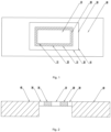
Fig. 1 is a first front schematic structural diagram of a battery top cover according to an embodiment of the present invention. -
Fig. 2 is a schematic structural diagram of a cross section of a battery top cover in a normal state according to an embodiment of the present invention. -
Fig. 3 is a schematic structural diagram of a cross section of a battery top cover in a pressure relief state according to an embodiment of the present invention. -
Fig. 4 is a schematic structural diagram of a local section of an explosion-proof valve according to an embodiment of the present invention. -
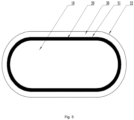
Fig. 5 is a second front schematic structural diagram of a battery top cover according to an embodiment of the present invention. -
Fig. 6 is a third front schematic structural diagram of a battery top cover according to an embodiment of the present invention. -
Fig. 7 is a schematic structural diagram of a first cross section of a battery top cover according to an embodiment of the present invention. -
Fig. 8 is a schematic structural diagram of a second cross section of a battery top cover according to an embodiment of the present invention. - Reference signs: 10. Explosion-proof valve cover; 11. First protrusion; 12. Positioning part; 13. Connecting part; 14. Cover plate;
- 20. Injection molded member; 21. Second inner ring part; 22. Second outer ring part; 23. First recess; 24. Second recess;
- 30. Explosion-proof valve seat; 31. First inner ring part; 32. First outer ring part; 33. Second protrusion; 34. First aperture part; 35. Second aperture part;
- 40. Top cover body; 41. Explosion-proof hole.
- In order to make the purposes, technical solutions and advantages of the present invention clearer, the technical solutions in the embodiments of the present invention will be clearly and completely described in conjunction with the drawings in the embodiments of the present invention. It is apparent that the described embodiments are only a part of the embodiments of the present invention, and not all of them. All other embodiments obtained by those of ordinary skill in the art based on the embodiments of the present invention without creative efforts are within the scope of the present invention.
- In the description of the present invention, it is to be understood that the orientations or positional relationships indicated by the terms "upper", "down", "top", "bottom", "inside", "outside", etc. are based on the orientations or positional relationships shown in the drawings, and are only for the convenience of describing the present invention and simplifying the description. The description does not indicate or imply that the device or element referred to must have a specific orientation, be constructed and operated in a specific orientation, and therefore cannot be construed as limiting the present invention. It is to be noted that when an element is considered to be "connected" to another component, it may be directly connected to another components or there is a centered components than at the same time.
- The specific implementations of the present invention are further described below in conjunction with the drawings and specific implementations.
- An explosion-proof valve provided in the embodiment is mainly applied to a battery housing of a lithium battery, in particular to a battery top cover of the lithium battery, to play the role of pressure relief of the lithium battery. By optimizing the structure of the explosion-proof valve, the influence of high temperature generated by welding may be eliminated when the explosion-proof valve is installed on various components by welding, thereby ensuring the safety of the explosion-proof valve.
- As shown in
Fig. 1 to Fig. 3 , the explosion-proof valve in the embodiment includes an explosion-proof valve cover 10 and an explosion-proof valve seat 30 connected to a battery in a welded manner, the explosion-proof valve cover 10 being made of a memory alloy material. The explosion-proof valve seat 30 is provided with a valve hole penetrating through the explosion-proof valve seat 30, the explosion-proof valve seat 30 includes a firstinner ring part 31 and a firstouter ring part 32, the explosion-proof valve cover 10 is arranged in the valve hole, and the explosion-proof valve cover 10 is connected to the firstinner ring part 31 in a non-welded manner and seals the valve hole. The explosion-proof valve cover 10 deforms at a temperature higher than a preset temperature control threshold, and a crack or a gap is formed between the deformed explosion-proof valve cover 10 and the explosion-proof valve seat 30. It is to be understood that a manner in which the explosion-proof valve cover 10 is arranged in the valve hole is not limited, and may be that the explosion-proof valve cover 10 is located in the valve hole and connected to the explosion-proof valve seat 30, or the explosion-proof valve cover 10 is located above the valve hole and connected to the explosion-proof valve seat 30, or part of the explosion-proof valve cover 10 is located in the valve hole, and other parts of the explosion-proof cover 10 are located above the valve hole and connected to the explosion-proof valve seat 30. - Specifically, the explosion-proof valve cover 10 is made of the memory alloy material, so that when the internal temperature of the lithium battery is higher than the preset temperature control threshold, the explosion-proof valve cover 10 may deform, the crack or the gap is formed between the explosion-proof valve cover 10 and the explosion-proof valve seat 30, and then high-temperature gas is discharged from the crack or the gap to avoid accidents caused by thermal runaway of the lithium battery; the explosion-proof valve seat 30 is connected to the explosion-proof valve cover 10 in a non-welded manner, so that the influence of the welding temperature on the explosion-proof valve cover 10 may be reduced, and it is ensured that the explosion-proof valve cover 10 has no phase change when the explosion-proof valve cover 10 is connected to the explosion-proof valve seat 30; and the battery top cover and the explosion-proof valve cover 10 are separated by the explosion-proof valve seat 30, so that heat generated when the explosion-proof valve seat 30 is welded to the battery top cover and other components does not affect the explosion-proof valve cover 10, and then it is ensured that the explosion-proof valve cover 10 has no phase change when the explosion-proof valve is welded to the battery top cover and other components, thereby ensuring the explosion-proof effect.
- It should be added that when the explosion-proof valve is molded, the explosion-
proof valve cover 10 and the explosion-proof valve seat 30 are placed into a mold, and a raw material is injected between the explosion-proof valve cover 10 and the explosion-proof valve seat 30 by means of injection molding. At the same time, the injection molding temperature needs to be controlled to ensure that the injection molding connection does not affect the explosion-proof valve cover 10, so that the raw material is molded into an injection moldedmember 20, and the explosion-proof valve cover 10 and the explosion-proof valve seat 30 are connected. In other optional implementations, the injection moldedmember 20 is a thermal insulation block pre-molded in advance, an inner side of the thermal insulation block is bonded to the explosion-proof valve cover 10 by means of glue, and an outer side of the thermal insulation block is bonded to the explosion-proof valve seat 30 by means of glue. - Exemplarily, as shown in
Fig. 2 andFig. 3 , when the lithium battery is in a thermal runaway state, the explosion-proof valve cover 10 deforms with the temperature rise, so that the crack or the gap is formed between the explosion-proof valve cover 10 and the secondinner ring part 21, and the high-temperature gas is discharged from the crack or the gap; the welding position of the explosion-proof valve seat 30 and the battery top cover and the explosion-proof valve cover 10 are at least separated by the firstouter ring part 32, the firstinner ring part 31, the secondouter ring part 22 and the secondinner ring part 21, so that the influence of the welding temperature on the explosion-proof valve cover 10 is further reduced to avoid the explosion-proof valve cover 10 having the phase change in advance, thereby further improving the explosion-proof performance and eliminating the potential safety hazards. - Further, the injection molding temperature is controllable, so that the explosion-
proof valve cover 10 is connected to the firstinner ring part 31 by means of injection molding. When the explosion-proof valve cover 10 is connected to the firstinner ring part 31, it is ensured that the explosion-proof valve cover 10 has no phase change by controlling the injection molding temperature, thereby achieving the purpose of convenient connection and sealing connection, while also ensuring that the explosion-proof valve cover 10 has no phase change. In other optional implementations, the firstinner ring part 31 is connected to the explosion-proof valve cover 10 by means of clamping connection, bonding and other forms. At the same time, it should be added that the outlines of the explosion-proof valve cover 10 and the firstinner ring part 31 are not specifically limited, as shown inFig. 1 , the explosion-proof valve cover 10 and the firstinner ring part 31 are rectangular, as shown inFig. 5 , the explosion-proof valve cover 10 and the firstinner ring part 31 are elliptical, and in other implementations, the explosion-proof valve cover 10 and the firstinner ring part 31 are circular, square and in other shapes. - In some embodiments, as shown in
Fig. 2 to Fig. 4 , the explosion-proof valve cover 10 is arranged in the valve hole. An annular cavity is formed between a peripheral wall of the explosion-proof valve cover 10 and a peripheral wall of the firstinner ring part 31, the injection moldedmember 20 is injection-molded in the annular cavity, and the explosion-proof valve cover 10 and the firstinner ring part 31 are integrally connected through the injection moldedmember 20. The specific shape of the explosion-proof valve cover 10 is not limited, but the shape of the explosion-proof valve cover 10 should be matched with the valve hole, for example, as shown inFig. 8 , when the explosion-proof valve cover 10 includes apositioning part 12 and a connectingpart 13 which are connected in sequence, the valve hole includes afirst aperture part 34 and asecond aperture part 35 which are connected in sequence, thepositioning part 12 is matched with thefirst aperture part 34 in an inserted manner, the annular cavity is formed between a peripheral wall of the connectingpart 13 and a hole wall of thesecond aperture part 35. Through the above arrangement, the explosion-proof valve cover 10 is positioned and pre-fixed in the explosion-proof valve seat 30, which is conducive to the molding of the subsequent injection moldedmember 20 in the annular cavity. - More specifically, the injection molded
member 20 includes the secondinner ring part 21 and the secondouter ring part 22. The secondinner ring part 21 sleeves the explosion-proof valve cover 10, and the firstinner ring part 31 sleeves the secondouter ring part 22. It is to be noted that the outlines of the secondinner ring part 21 and the secondouter ring part 22 are not limited, for example, the secondinner ring part 21 and the secondouter ring part 22 in the embodiment are rectangular, and in other optional implementations, the secondinner ring part 21 and/or the secondouter ring part 22 is circular. It should be added that the explosion-proof valve seat 30 is made of a metal material that is able to configure for welding, and the explosion-proof valve seat 30 is welded to atop cover body 40 of the battery top cover, so that the explosion-proof valve is installed on the battery top cover. - In some embodiments, an inner peripheral wall of the injection molded
member 20 is matched with at least part of the peripheral wall of the explosion-proof valve cover 10 in a concave-convex manner; and/or an outer peripheral wall of the injection moldedmember 20 is matched with at least part of the peripheral wall of the firstinner ring part 31 in a concave-convex manner. It is to be understood that the injection moldedmember 20 is matched with the explosion-proof valve cover 10 in a concave-convex manner, and the injection moldedmember 20 is matched with the firstinner ring part 31 in a concave-convex manner, so that the contact area between the above components may be increased, and the explosion-proof valve cover 10 and the firstinner ring part 31 may be more stably connected through the injection moldedmember 20. Moreover, it is to be understood that the more stable connection may be achieved as long as the contact area is increased, so that the peripheral wall of the injection moldedmember 20 is partially or fully matched with the peripheral wall of the explosion-proof valve cover 10 in a concave-convex manner, and the outer peripheral wall of the injection moldedmember 20 is partially or fully matched with the peripheral wall of the firstinner ring part 31 in a concave-convex manner. - More specifically, as shown in
Fig. 1 andFig. 4 , a plurality offirst protrusions 11 are formed on part or all of a wall surface of the explosion-proof valve cover 10 towards the secondinner ring part 21, andfirst recesses 23 are formed at positions, corresponding to thefirst protrusions 11, of the secondinner ring part 21. The first recesses 23 are in one-to-one correspondence with thefirst protrusions 11, and thefirst protrusions 11 are embedded in the first recesses 23. It is to be understood that a contact surface between the explosion-proof valve cover 10 and the injection moldedmember 20 includes at least a contact surface between thefirst protrusion 11 and thefirst recess 23, thereby increasing the contact area between the injection moldedmember 20 and the explosion-proof valve cover 10. When the injection moldedmember 20 is injection-molded, due to the increase in the contact area, the connection force between the injection moldedmember 20 and the explosion-proof valve cover 10 is improved, thereby improving the connection stability of the injection moldedmember 20 and the explosion-proof valve cover 10. - As shown in
Fig. 1 andFig. 4 , a plurality ofsecond protrusions 33 are formed on part or all of a wall surface of the firstinner ring part 31 towards the secondouter ring part 22, andsecond recesses 24 are formed at positions, corresponding to thesecond protrusions 33, of the secondouter ring part 22. The second recesses 24 are in one-to-one correspondence with thesecond protrusions 33, and thesecond protrusions 33 are embedded in the second recesses 24. It is to be understood that a contact surface between the explosion-proof valve cover 30 and the injection moldedmember 20 includes at least a contact surface between thesecond protrusion 33 and thesecond recess 24, thereby increasing the contact area between the injection moldedmember 20 and the explosion-proof valve cover 30. When the injection moldedmember 20 is injection-molded, due to the increase in the contact area, the connection force between the injection moldedmember 20 and the explosion-proof valve cover 30 is improved, thereby improving the connection stability of the injection moldedmember 20 and the explosion-proof valve cover 30. - In some embodiments, the
first protrusions 11 are formed on the peripheral wall of the explosion-proof valve cover 10 by means of chemical corrosion; and/or thesecond protrusions 33 are formed on the peripheral wall of the firstinner ring part 31 by means of chemical corrosion, so that a concave-convex structure is obtained by means of chemical corrosion, and the processing is faster. - In some embodiments, as shown in
Fig. 6 , the explosion-proof valve cover 10 is composed of at least twocover plates 14, and the at least twocover plates 14 are integrally connected by means of injection molding. It is to be understood that thecover plates 14 are made of a memory alloy material, so that when the temperature rises, a gap is generated between the twoadjacent cover plates 14, which helps the high-temperature gas to be discharged, thereby improving the explosion-proof effect. - In the embodiment, the volume of the explosion-
proof valve cover 10 becomes smaller at the temperature higher than the preset temperature control threshold, thereby generating a gap with the injection moldedmember 20, that is, the memory metal material contracted at high temperature is selected. In other optional implementations, the volume of the explosion-proof valve cover 10 becomes larger at the temperature higher than the preset temperature control threshold, so that the crack is formed between the injection moldedmember 20 and the explosion-proof valve cover 10, and the high temperature gas is discharged from the crack, that is, the memory metal material expanded at high temperature is selected. - In the embodiment, the preset temperature control threshold ranges from 95°C to 140°C, preferably 120°C, of course, may also be 95°C or 100°C or 140°C.
- In summary, the explosion-proof valve provided in the embodiment has the advantages of high production yield, high safety, high stability, reliable connection and the like.
- A battery top cover provided in the embodiment includes a
top cover body 40 and the explosion-proof valve in Embodiment 1. An explosion-proof valve seat 30 is connected to thetop cover body 40 by means of welding. Specifically, as shown inFig. 1 to Fig. 3 , thetop cover body 40 is provided with an explosion-proof hole 41, and a firstouter ring part 32 of the explosion-proof valve is welded to thetop cover body 40 and seals the explosion-proof hole 41. The specific structure and technical effect of the explosion-proof valve are described in Embodiment 1. The battery top cover in the embodiment refers to the structure and also has the technical effect thereof. - In summary, the battery top cover provided in the embodiment has the advantages of high production yield, high safety, high stability, reliable connection and the like.
- A lithium battery provided in the embodiment includes a battery top cover and a battery housing. The battery top cover and/or the battery housing are/is connected to the explosion-proof valve in Embodiment 1 by means of welding. The specific structure and technical effect of the explosion-proof valve are described in Embodiment 1. The lithium battery in the embodiment refers to the structure and also has the technical effect thereof.
- In summary, the lithium battery provided in the embodiment has the advantages of high production yield, high safety, high stability, reliable connection and the like.
- In summary, the above embodiments are only intended to illustrate the technical solutions of the present invention, but not intended to limit the present invention. Although the present invention is described in detail with reference to the foregoing embodiments, it should be understood by those of ordinary skill in the art that: they may still make modifications to the technical solutions described in the foregoing embodiments or equivalent replacements to part of the technical features without any modification of the technical solutions or departures from the spirit and scope of the technical solutions of the embodiments of the present invention.
Claims (15)
- An explosion-proof valve, comprising an explosion-proof valve cover (10) and an explosion-proof valve seat (30) connected to a battery in a welded manner, the explosion-proof valve cover (10) being made of a memory alloy material;the explosion-proof valve seat (30) is provided with a valve hole penetrating through the explosion-proof valve seat (30), the explosion-proof valve seat (30) comprises a first inner ring part (31) and a first outer ring part (32), the explosion-proof valve cover (10) is arranged in the valve hole, and the explosion-proof valve cover (10) is connected to the first inner ring part (31) in a non-welded manner and seals the valve hole;wherein the explosion-proof valve cover (10) deforms at a temperature higher than a preset temperature control threshold, and a crack or a gap is formed between the deformed explosion-proof valve cover (10) and the explosion-proof valve seat (30).
- The explosion-proof valve as claimed in claim 1, wherein the explosion-proof valve cover (10) is connected to the first inner ring part (31) by means of injection molding.
- The explosion-proof valve as claimed in claim 2, wherein the explosion-proof valve cover (10) is arranged in the valve hole; and
an annular cavity is formed between a peripheral wall of the explosion-proof valve cover (10) and a peripheral wall of the first inner ring part (31), an injection molded member (20) is injection-molded in the annular cavity, and the explosion-proof valve cover (10) and the first inner ring part (31) are integrally connected through the injection molded member (20). - The explosion-proof valve as claimed in claim 3, wherein an inner peripheral wall of the injection molded member (20) is matched with at least part of the peripheral wall of the explosion-proof valve cover (10) in a concave-convex manner; and/or an outer peripheral wall of the injection molded member (20) is matched with at least part of the peripheral wall of the first inner ring part (31) in a concave-convex manner.
- The explosion-proof valve as claimed in claim 4, wherein first protrusions (11) are formed on the peripheral wall of the explosion-proof valve cover (10) by means of chemical corrosion; and/or second protrusions (33) are formed on the peripheral wall of the first inner ring part (31) by means of chemical corrosion.
- The explosion-proof valve as claimed in claim 1, wherein the explosion-proof valve cover (10) comprises a positioning part (12) and a connecting part (13) which are connected in sequence, the valve hole comprises a first aperture part (34) and a second aperture part (35) which are connected in sequence, the positioning part (12) is matched with the first aperture part (34) in an inserted manner, and an annular cavity is formed between a peripheral wall of the connecting part (13) and a hole wall of the second aperture part (35).
- The explosion-proof valve as claimed in claim 1, wherein the explosion-proof valve cover (10) and the first inner ring part (31) are any one of elliptical, circular and square.
- The explosion-proof valve as claimed in claim 3, wherein the injection molded member (20) comprises the second inner ring part (21) and the second outer ring part (22), the second inner ring part (21) sleeves the explosion-proof valve cover (10), and the first inner ring part (31) sleeves the second outer ring part (22).
- The explosion-proof valve as claimed in claim 8, wherein the second inner ring part (21) and the second outer ring part (22) are any one of rectangular and circular.
- The explosion-proof valve as claimed in claim 3, wherein the injection molded member (20) is a thermal insulation block pre-molded in advance, an inner side of the thermal insulation block is bonded to the explosion-proof valve cover (10) by means of glue, and an outer side of the thermal insulation block is bonded to the explosion-proof valve seat (30) by means of glue.
- The explosion-proof valve as claimed in claim 1, wherein the explosion-proof valve cover (10) is composed of at least two cover plates (14), and the at least two cover plates (14) are integrally connected by means of injection molding.
- The explosion-proof valve as claimed in claim 1, wherein the volume of the explosion-proof valve cover (10) becomes smaller at the temperature higher than the preset temperature control threshold.
- The explosion-proof valve as claimed in claim 1, wherein the preset temperature control threshold ranges from 95°C to 140°C.
- A battery top cover, comprising a top cover body (40) and the explosion-proof valve as claimed in any one of claims 1 to 13, wherein the top cover body (40) is provided with an explosion-proof hole (41), and the first outer ring part (32) of the explosion-proof valve is welded to the top cover body (40) and seals the explosion-proof hole (41).
- A lithium battery, comprising a battery housing, the battery housing comprising the explosion-proof valve as claimed in any one of claims 1 to 13, the first outer ring part (32) of the explosion-proof valve being connected to the battery housing in the welded manner.
Applications Claiming Priority (1)
| Application Number | Priority Date | Filing Date | Title |
|---|---|---|---|
| CN202320455734.3U CN219419391U (en) | 2023-03-10 | 2023-03-10 | Explosion-proof valve, battery top cover and lithium battery |
Publications (3)
| Publication Number | Publication Date |
|---|---|
| EP4429009A1 true EP4429009A1 (en) | 2024-09-11 |
| EP4429009B1 EP4429009B1 (en) | 2025-10-29 |
| EP4429009C0 EP4429009C0 (en) | 2025-10-29 |
Family
ID=87239320
Family Applications (1)
| Application Number | Title | Priority Date | Filing Date |
|---|---|---|---|
| EP24162469.1A Active EP4429009B1 (en) | 2023-03-10 | 2024-03-08 | Explosion-proof valve, battery top cover and lithium battery |
Country Status (3)
| Country | Link |
|---|---|
| US (1) | US20240304936A1 (en) |
| EP (1) | EP4429009B1 (en) |
| CN (1) | CN219419391U (en) |
Cited By (1)
| Publication number | Priority date | Publication date | Assignee | Title |
|---|---|---|---|---|
| CN119725967A (en) * | 2024-12-23 | 2025-03-28 | 厦门海辰储能科技股份有限公司 | Energy storage devices and electrical equipment |
Families Citing this family (2)
| Publication number | Priority date | Publication date | Assignee | Title |
|---|---|---|---|---|
| EP4661171A1 (en) * | 2024-06-03 | 2025-12-10 | Volvo Car Corporation | Battery cell lid assembly for a battery cell of a vehicle, battery cell, filler material component, battery pack, vehicle and method |
| CN120127303B (en) * | 2025-02-21 | 2025-12-16 | 蜂巢能源科技股份有限公司 | Cover assembly, individual cells and battery pack |
Citations (5)
| Publication number | Priority date | Publication date | Assignee | Title |
|---|---|---|---|---|
| JP4991186B2 (en) * | 2006-06-07 | 2012-08-01 | Necエナジーデバイス株式会社 | Sealed battery |
| JP2015185223A (en) * | 2014-03-20 | 2015-10-22 | 日立マクセル株式会社 | sealed battery |
| EP3252849A1 (en) * | 2015-08-21 | 2017-12-06 | LG Chem, Ltd. | Cap assembly |
| WO2019232390A1 (en) * | 2018-05-31 | 2019-12-05 | Cps Technology Holdings Llc | Shape memory alloy hermetic seal in lithium ion batteries |
| CN114843667A (en) * | 2022-05-24 | 2022-08-02 | 厦门海辰新能源科技有限公司 | Cover plate assembly of battery and battery |
-
2023
- 2023-03-10 CN CN202320455734.3U patent/CN219419391U/en active Active
-
2024
- 2024-03-08 EP EP24162469.1A patent/EP4429009B1/en active Active
- 2024-03-09 US US18/600,703 patent/US20240304936A1/en active Pending
Patent Citations (5)
| Publication number | Priority date | Publication date | Assignee | Title |
|---|---|---|---|---|
| JP4991186B2 (en) * | 2006-06-07 | 2012-08-01 | Necエナジーデバイス株式会社 | Sealed battery |
| JP2015185223A (en) * | 2014-03-20 | 2015-10-22 | 日立マクセル株式会社 | sealed battery |
| EP3252849A1 (en) * | 2015-08-21 | 2017-12-06 | LG Chem, Ltd. | Cap assembly |
| WO2019232390A1 (en) * | 2018-05-31 | 2019-12-05 | Cps Technology Holdings Llc | Shape memory alloy hermetic seal in lithium ion batteries |
| CN114843667A (en) * | 2022-05-24 | 2022-08-02 | 厦门海辰新能源科技有限公司 | Cover plate assembly of battery and battery |
Cited By (2)
| Publication number | Priority date | Publication date | Assignee | Title |
|---|---|---|---|---|
| CN119725967A (en) * | 2024-12-23 | 2025-03-28 | 厦门海辰储能科技股份有限公司 | Energy storage devices and electrical equipment |
| CN119725967B (en) * | 2024-12-23 | 2025-10-28 | 厦门海辰储能科技股份有限公司 | Energy storage devices and electrical equipment |
Also Published As
| Publication number | Publication date |
|---|---|
| CN219419391U (en) | 2023-07-25 |
| EP4429009B1 (en) | 2025-10-29 |
| EP4429009C0 (en) | 2025-10-29 |
| US20240304936A1 (en) | 2024-09-12 |
Similar Documents
| Publication | Publication Date | Title |
|---|---|---|
| EP4429009A1 (en) | Explosion-proof valve, battery top cover and lithium battery | |
| WO2023151320A1 (en) | Battery cover plate assembly, cylindrical battery, and battery pack | |
| EP3907816B1 (en) | Secondary battery | |
| CN203218359U (en) | Pressure relief valve and power battery top cover | |
| JP5224324B2 (en) | Sealed battery | |
| US11742542B2 (en) | Explosion-proof enclosure for energy storage device and energy storage device | |
| JP2009110808A (en) | Sealed battery | |
| JP3244519U (en) | Battery cover for cylindrical batteries and cylindrical batteries | |
| CN217158534U (en) | Explosion-proof valve, battery cover plate and battery | |
| CN218827684U (en) | Battery, battery pack and electric equipment | |
| WO2022110893A1 (en) | Cylindrical lithium battery | |
| US20230402688A1 (en) | Battery cover plate and lithium-ion secondary battery | |
| WO2026066458A1 (en) | Cover plate assembly and battery cell | |
| CN119009290A (en) | Battery cover plate structure and battery | |
| WO2025246487A1 (en) | Battery cell cover plate and battery cell | |
| WO2023087556A1 (en) | Cover plate of lithium ion battery, and lithium ion battery comprising cover plate and explosion-proof method therefor | |
| CN219892345U (en) | Battery cell cover assembly and battery cell | |
| CN217788479U (en) | Cell and battery module with sealed rolling groove | |
| CN206040730U (en) | Battery cover and battery | |
| CN116315334A (en) | Battery cover structure, cylindrical battery and preparation method | |
| CN115377577A (en) | End cover assembly, battery sealing method, battery module and electric equipment | |
| CN216720257U (en) | Battery with a battery cell | |
| JP3682390B2 (en) | Sealed parts with safety valve | |
| WO2026056221A1 (en) | Battery cell cover plate and battery cell | |
| CN118763349A (en) | Battery and battery pack |
Legal Events
| Date | Code | Title | Description |
|---|---|---|---|
| PUAI | Public reference made under article 153(3) epc to a published international application that has entered the european phase |
Free format text: ORIGINAL CODE: 0009012 |
|
| STAA | Information on the status of an ep patent application or granted ep patent |
Free format text: STATUS: REQUEST FOR EXAMINATION WAS MADE |
|
| 17P | Request for examination filed |
Effective date: 20240308 |
|
| AK | Designated contracting states |
Kind code of ref document: A1 Designated state(s): AL AT BE BG CH CY CZ DE DK EE ES FI FR GB GR HR HU IE IS IT LI LT LU LV MC ME MK MT NL NO PL PT RO RS SE SI SK SM TR |
|
| GRAP | Despatch of communication of intention to grant a patent |
Free format text: ORIGINAL CODE: EPIDOSNIGR1 |
|
| STAA | Information on the status of an ep patent application or granted ep patent |
Free format text: STATUS: GRANT OF PATENT IS INTENDED |
|
| INTG | Intention to grant announced |
Effective date: 20250522 |
|
| GRAS | Grant fee paid |
Free format text: ORIGINAL CODE: EPIDOSNIGR3 |
|
| GRAA | (expected) grant |
Free format text: ORIGINAL CODE: 0009210 |
|
| STAA | Information on the status of an ep patent application or granted ep patent |
Free format text: STATUS: THE PATENT HAS BEEN GRANTED |
|
| AK | Designated contracting states |
Kind code of ref document: B1 Designated state(s): AL AT BE BG CH CY CZ DE DK EE ES FI FR GB GR HR HU IE IS IT LI LT LU LV MC ME MK MT NL NO PL PT RO RS SE SI SK SM TR |
|
| RAP3 | Party data changed (applicant data changed or rights of an application transferred) |
Owner name: JIANGSU ZENERGY BATTERY TECHNOLOGIES GROUPCO., LTD. |
|
| REG | Reference to a national code |
Ref country code: CH Ref legal event code: F10 Free format text: ST27 STATUS EVENT CODE: U-0-0-F10-F00 (AS PROVIDED BY THE NATIONAL OFFICE) Effective date: 20251029 Ref country code: GB Ref legal event code: FG4D |
|
| REG | Reference to a national code |
Ref country code: DE Ref legal event code: R096 Ref document number: 602024001053 Country of ref document: DE |
|
| REG | Reference to a national code |
Ref country code: IE Ref legal event code: FG4D |
|
| U01 | Request for unitary effect filed |
Effective date: 20251120 |
|
| U07 | Unitary effect registered |
Designated state(s): AT BE BG DE DK EE FI FR IT LT LU LV MT NL PT RO SE SI Effective date: 20251125 |
|
| PG25 | Lapsed in a contracting state [announced via postgrant information from national office to epo] |
Ref country code: ES Free format text: LAPSE BECAUSE OF FAILURE TO SUBMIT A TRANSLATION OF THE DESCRIPTION OR TO PAY THE FEE WITHIN THE PRESCRIBED TIME-LIMIT Effective date: 20251029 |
|
| PG25 | Lapsed in a contracting state [announced via postgrant information from national office to epo] |
Ref country code: NO Free format text: LAPSE BECAUSE OF FAILURE TO SUBMIT A TRANSLATION OF THE DESCRIPTION OR TO PAY THE FEE WITHIN THE PRESCRIBED TIME-LIMIT Effective date: 20260129 |
|
| PG25 | Lapsed in a contracting state [announced via postgrant information from national office to epo] |
Ref country code: HR Free format text: LAPSE BECAUSE OF FAILURE TO SUBMIT A TRANSLATION OF THE DESCRIPTION OR TO PAY THE FEE WITHIN THE PRESCRIBED TIME-LIMIT Effective date: 20251029 |
|
| PGFP | Annual fee paid to national office [announced via postgrant information from national office to epo] |
Ref country code: HU Payment date: 20260226 Year of fee payment: 3 |
|
| PG25 | Lapsed in a contracting state [announced via postgrant information from national office to epo] |
Ref country code: RS Free format text: LAPSE BECAUSE OF FAILURE TO SUBMIT A TRANSLATION OF THE DESCRIPTION OR TO PAY THE FEE WITHIN THE PRESCRIBED TIME-LIMIT Effective date: 20260129 |
|
| PG25 | Lapsed in a contracting state [announced via postgrant information from national office to epo] |
Ref country code: IS Free format text: LAPSE BECAUSE OF FAILURE TO SUBMIT A TRANSLATION OF THE DESCRIPTION OR TO PAY THE FEE WITHIN THE PRESCRIBED TIME-LIMIT Effective date: 20260228 |
|
| PG25 | Lapsed in a contracting state [announced via postgrant information from national office to epo] |
Ref country code: PL Free format text: LAPSE BECAUSE OF FAILURE TO SUBMIT A TRANSLATION OF THE DESCRIPTION OR TO PAY THE FEE WITHIN THE PRESCRIBED TIME-LIMIT Effective date: 20251029 |