EP4429003A1 - Power tool and battery pack - Google Patents
Power tool and battery pack Download PDFInfo
- Publication number
- EP4429003A1 EP4429003A1 EP24153811.5A EP24153811A EP4429003A1 EP 4429003 A1 EP4429003 A1 EP 4429003A1 EP 24153811 A EP24153811 A EP 24153811A EP 4429003 A1 EP4429003 A1 EP 4429003A1
- Authority
- EP
- European Patent Office
- Prior art keywords
- battery pack
- battery
- polyurea coating
- housing assembly
- battery cells
- Prior art date
- Legal status (The legal status is an assumption and is not a legal conclusion. Google has not performed a legal analysis and makes no representation as to the accuracy of the status listed.)
- Pending
Links
Images



Classifications
-
- H—ELECTRICITY
- H01—ELECTRIC ELEMENTS
- H01M—PROCESSES OR MEANS, e.g. BATTERIES, FOR THE DIRECT CONVERSION OF CHEMICAL ENERGY INTO ELECTRICAL ENERGY
- H01M50/00—Constructional details or processes of manufacture of the non-active parts of electrochemical cells other than fuel cells, e.g. hybrid cells
- H01M50/20—Mountings; Secondary casings or frames; Racks, modules or packs; Suspension devices; Shock absorbers; Transport or carrying devices; Holders
- H01M50/233—Mountings; Secondary casings or frames; Racks, modules or packs; Suspension devices; Shock absorbers; Transport or carrying devices; Holders characterised by physical properties of casings or racks, e.g. dimensions
- H01M50/242—Mountings; Secondary casings or frames; Racks, modules or packs; Suspension devices; Shock absorbers; Transport or carrying devices; Holders characterised by physical properties of casings or racks, e.g. dimensions adapted for protecting batteries against vibrations, collision impact or swelling
-
- H—ELECTRICITY
- H01—ELECTRIC ELEMENTS
- H01M—PROCESSES OR MEANS, e.g. BATTERIES, FOR THE DIRECT CONVERSION OF CHEMICAL ENERGY INTO ELECTRICAL ENERGY
- H01M10/00—Secondary cells; Manufacture thereof
- H01M10/42—Methods or arrangements for servicing or maintenance of secondary cells or secondary half-cells
- H01M10/425—Structural combination with electronic components, e.g. electronic circuits integrated to the outside of the casing
- H01M10/4257—Smart batteries, e.g. electronic circuits inside the housing of the cells or batteries
-
- H—ELECTRICITY
- H01—ELECTRIC ELEMENTS
- H01M—PROCESSES OR MEANS, e.g. BATTERIES, FOR THE DIRECT CONVERSION OF CHEMICAL ENERGY INTO ELECTRICAL ENERGY
- H01M50/00—Constructional details or processes of manufacture of the non-active parts of electrochemical cells other than fuel cells, e.g. hybrid cells
- H01M50/20—Mountings; Secondary casings or frames; Racks, modules or packs; Suspension devices; Shock absorbers; Transport or carrying devices; Holders
- H01M50/204—Racks, modules or packs for multiple batteries or multiple cells
- H01M50/207—Racks, modules or packs for multiple batteries or multiple cells characterised by their shape
- H01M50/211—Racks, modules or packs for multiple batteries or multiple cells characterised by their shape adapted for pouch cells
-
- H—ELECTRICITY
- H01—ELECTRIC ELEMENTS
- H01M—PROCESSES OR MEANS, e.g. BATTERIES, FOR THE DIRECT CONVERSION OF CHEMICAL ENERGY INTO ELECTRICAL ENERGY
- H01M50/00—Constructional details or processes of manufacture of the non-active parts of electrochemical cells other than fuel cells, e.g. hybrid cells
- H01M50/20—Mountings; Secondary casings or frames; Racks, modules or packs; Suspension devices; Shock absorbers; Transport or carrying devices; Holders
- H01M50/233—Mountings; Secondary casings or frames; Racks, modules or packs; Suspension devices; Shock absorbers; Transport or carrying devices; Holders characterised by physical properties of casings or racks, e.g. dimensions
- H01M50/24—Mountings; Secondary casings or frames; Racks, modules or packs; Suspension devices; Shock absorbers; Transport or carrying devices; Holders characterised by physical properties of casings or racks, e.g. dimensions adapted for protecting batteries from their environment, e.g. from corrosion
-
- H—ELECTRICITY
- H01—ELECTRIC ELEMENTS
- H01M—PROCESSES OR MEANS, e.g. BATTERIES, FOR THE DIRECT CONVERSION OF CHEMICAL ENERGY INTO ELECTRICAL ENERGY
- H01M50/00—Constructional details or processes of manufacture of the non-active parts of electrochemical cells other than fuel cells, e.g. hybrid cells
- H01M50/20—Mountings; Secondary casings or frames; Racks, modules or packs; Suspension devices; Shock absorbers; Transport or carrying devices; Holders
- H01M50/247—Mountings; Secondary casings or frames; Racks, modules or packs; Suspension devices; Shock absorbers; Transport or carrying devices; Holders specially adapted for portable devices, e.g. mobile phones, computers, hand tools or pacemakers
-
- H—ELECTRICITY
- H01—ELECTRIC ELEMENTS
- H01M—PROCESSES OR MEANS, e.g. BATTERIES, FOR THE DIRECT CONVERSION OF CHEMICAL ENERGY INTO ELECTRICAL ENERGY
- H01M2220/00—Batteries for particular applications
- H01M2220/30—Batteries in portable systems, e.g. mobile phone, laptop
-
- Y—GENERAL TAGGING OF NEW TECHNOLOGICAL DEVELOPMENTS; GENERAL TAGGING OF CROSS-SECTIONAL TECHNOLOGIES SPANNING OVER SEVERAL SECTIONS OF THE IPC; TECHNICAL SUBJECTS COVERED BY FORMER USPC CROSS-REFERENCE ART COLLECTIONS [XRACs] AND DIGESTS
- Y02—TECHNOLOGIES OR APPLICATIONS FOR MITIGATION OR ADAPTATION AGAINST CLIMATE CHANGE
- Y02E—REDUCTION OF GREENHOUSE GAS [GHG] EMISSIONS, RELATED TO ENERGY GENERATION, TRANSMISSION OR DISTRIBUTION
- Y02E60/00—Enabling technologies; Technologies with a potential or indirect contribution to GHG emissions mitigation
- Y02E60/10—Energy storage using batteries
Definitions
- the present disclosure relates to the field of power tools and, in particular, to a battery pack with better impact resistance.
- the battery pack When a user works with a power tool provided with a battery pack, the battery pack may detach from the power tool body and fall to the ground due to careless operation. Especially if the battery pack falls to the ground during working at high altitudes, the housing or the battery cells in the housing may be damaged. Some users even habitually use the battery pack provided on the tool as a hammer when using the power tool, leading to a risk of the battery pack being damaged.
- an object of the present application is to provide a battery pack and a power tool with better impact resistance.
- a power tool includes a tool body; an electric motor disposed in the tool body; and a power interface configured to be connected to a battery pack for supplying power to the electric motor.
- the battery pack includes a housing assembly; a battery cell module disposed in the housing assembly and including at least multiple battery cells; a circuit board disposed in the housing assembly and electrically connected to the multiple battery cells; a battery terminal electrically connected to the multiple battery cells to connect the multiple battery cells to an electrical device for transmitting electric power; and a polyurea coating applied to at least part of the housing assembly.
- the polyurea coating is applied to at least one of the tool body, the battery cell module, the circuit board, and a connector connecting the multiple battery cells.
- the power tool further includes a tool accessory, where the polyurea coating is applied to at least the tool accessory.
- the curing time for the polyurea coating is less than equal to 20 min.
- the battery cell module further includes a cell holder configured to support the multiple battery cells, and the polyurea coating is applied to the cell holder and/or at least one of the multiple battery cells.
- the cell holder includes a portion that is exposed after the battery pack is assembled, and the polyurea coating is applied to at least an external surface of the exposed cell holder.
- the polyurea coating is applied to at least part of an external surface and/or at least part of an internal surface of the housing assembly.
- the thickness of the polyurea coating applied to the at least part of the housing assembly is less than or equal to 5 mm.
- the circuit board includes a substrate, an electronic component supported on the substrate, and a base coating applied to at least the electronic component, where the polyurea coating is applied to the base coating.
- the base coating is applied to the substrate and/or the electronic component.
- a battery pack includes a housing assembly; a battery cell module disposed in the housing assembly and including at least multiple battery cells; a circuit board disposed in the housing assembly and electrically connected to the multiple battery cells; a battery terminal electrically connected to the multiple battery cells to connect the multiple battery cells to an electrical device for transmitting electric power; and a polyurea coating applied to at least part of the housing assembly.
- the polyurea coating is applied to at least one of the battery cell module, the circuit board, and a connector connecting the multiple battery cells.
- the battery cell module further includes a cell holder configured to support the multiple battery cells, and the polyurea coating is applied to the cell holder and/or at least one of the multiple battery cells.
- the cell holder includes a portion that is exposed after the battery pack is assembled, and the polyurea coating is applied to at least an external surface of the exposed cell holder.
- the polyurea coating is applied to at least part of an external surface and/or at least part of an internal surface of the housing assembly.
- the thickness of the polyurea coating applied to the at least part of the housing assembly is less than or equal to 5 mm.
- the curing time for the polyurea coating is controllable.
- the curing time for the polyurea coating is less than equal to 20 min.
- the circuit board includes a substrate, an electronic component supported on the substrate, and a base coating applied to at least the electronic component, where the polyurea coating is applied to the base coating.
- the base coating is applied to the substrate and the electronic component.
- the benefit of the present application is that the impact resistance of the battery pack is improved by spraying a highly elastomeric polyurea coating on the housing assembly of the battery pack.
- the term "and/or” is a kind of association relationship describing the relationship between associated objects, which means that there can be three kinds of relationships.
- a and/or B can indicate that A exists alone, A and B exist simultaneously, and B exists alone.
- the character "/" in this application generally indicates that the contextual associated objects belong to an "and/or” relationship.
- connection may be direct connection, combination, coupling or installation, and may also be indirect connection, combination, coupling or installation.
- direct connection means that two members or assemblies are connected together without intermediaries
- indirect connection means that two members or assemblies are respectively connected with at least one intermediate members and the two members or assemblies are connected by the at least one intermediate members.
- connection and “coupling” are not limited to physical or mechanical connections or couplings, and may include electrical connections or couplings.
- a relative term (such as “about”, “approximately”, and “substantially) used in conjunction with quantity or condition includes a stated value and has a meaning dictated by the context.
- the relative term includes at least a degree of error associated with the measurement of a particular value, a tolerance caused by manufacturing, assembly, and use associated with the particular value, and the like.
- Such relative term should also be considered as disclosing the range defined by the absolute values of the two endpoints.
- the relative term may refer to plus or minus of a certain percentage (such as 1%, 5%, 10%, or more) of an indicated value. A value that did not use the relative term should also be disclosed as a particular value with a tolerance.
- “substantially” when expressing a relative angular position relationship may refer to adding or subtracting a certain degree (such as 1 degree, 5 degrees, 10 degrees or more) to the indicated angle.
- a function performed by an assembly may be performed by one assembly, multiple assemblies, one member, or multiple members.
- a function performed by a member may be performed by one member, an assembly, or a combination of members.
- controller In this application, the terms “controller”, “processor”, “central processor”, “CPU” and “MCU” are interchangeable. Where a unit “controller”, “processor”, “central processing”, “CPU”, or “MCU” is used to perform a specific function, the specific function may be implemented by a single aforementioned unit or a plurality of the aforementioned unit.
- the term "device”, “module” or “unit” may be implemented in the form of hardware or software to achieve specific functions.
- the terms “computing”, “judging”, “controlling”, “determining”, “recognizing” and the like refer to the operations and processes of a computer system or similar electronic computing device (e.g., controller, processor, etc.).
- the power tool 10 includes a tool body 101, an electric motor 102, and a power interface 103.
- the power interface 103 may be connected to a battery pack 104.
- the battery pack 104 involved here can be adapted to various types of power tools 10.
- the power tool 10 may be a handheld power tool, such as a drill, a hedge trimmer, or a sander.
- the power tool 10 may be a table tool, such as a table saw or a miter saw.
- the power tool 10 may be a push power tool, such as a push mower or a push snow thrower.
- the power tool 10 may be a riding power tool, such as a riding mower, a riding vehicle, or an all-terrain vehicle.
- the power tool 10 may be a robotic tool, such as a robotic mower or a robotic snow thrower.
- the power tool 10 may be an electric drill, an electric lamp, an electric vehicle, or the like.
- the power tool 10 may be a garden tool, such as a hedge trimmer, a blower, a mower, or a chain saw.
- the power tool 10 may be a decorating tool, such as a screwdriver, a nail gun, a circular saw, or a sander.
- the power tool 10 may be a vegetation care tool, such as a grass trimmer, a mower, a hedge trimmer, or a chain saw.
- the power tool 10 may be a cleaning tool, such as a blower, a snow thrower, or a washer.
- the power tool 10 may be a drill-like tool, such as a drill, a screwdriver, a wrench, or an electric hammer.
- the power tool 10 may be a saw-like tool, such as a reciprocating saw, a jigsaw, or a circular saw.
- the power tool 10 may be a table tool, such as a table saw, a miter saw, a metal cutter, or an electric router.
- the power tool 10 may be a sanding tool, such as an angle grinder or a sander.
- the power tool 10 may be another tool, such as a lamp or a fan.
- the battery pack 104 in the example of the present application may be a liquid lithium-ion battery with a polymer housing, a pouch battery, or a hard pack battery using hard materials as the battery housing.
- the housing of the hard pack battery may be made of plastic, steel, or aluminum.
- the battery cells in the battery pack 104 may be cylindrical cells, square cells, or sheet cells.
- the battery pack 104 may be a lithium iron phosphate battery, a ternary lithium battery, a sodium-ion battery, or the like.
- the battery pack 104 in FIG. 1 may include the battery pack in the examples below.
- a battery pack 100 shown in FIG. 2 is a pouch battery.
- the battery pack 100 includes a housing assembly 11, a battery cell module 12 disposed in the housing assembly 11, a circuit board 13, and a battery terminal 14.
- the battery cell module 12 may include at least multiple battery cells 121, which may also be referred to as cell units or cells.
- a connector (not shown) is disposed between at least two battery cells 121, and the connector can electrically connect at least two battery cells 121.
- the housing assembly 11 may include an upper housing 111 and a lower housing 112. After being assembled, the upper housing 111 and the lower housing 112 can form an accommodation space for fixing and accommodating the battery cell module 12 and the circuit board 13.
- a battery interface 113 is formed on the surface of the upper housing 111 or the lower housing 112, and the battery terminal 14 is located in the battery interface 113.
- the battery terminal 14 is electrically connected to the battery cells 121, and the battery terminal 14 includes at least a positive battery terminal and a negative battery terminal and may further include a communication terminal.
- the battery pack 100 may be electrically connected to a tool terminal on the power tool housing through the battery terminal 14 to transmit electric power or communicate data between the battery pack 100 and the power tool.
- the battery terminal 14 is disposed on the circuit board 13.
- the circuit board 13 may also be provided with other electronic components, such as a battery management chip that manages the charging and discharging of the battery pack 100.
- the circuit board 13 and the electronic components or the battery terminal 14 disposed on the circuit board 13 may be electrically connected through wires. Different battery cells 121 may be electrically connected using cell connectors or wires. Any welding manner such as spot welding, line welding, surface welding, ultrasonic welding, or laser spot welding may be adopted between the battery cells 121 and the wires, the circuit board 13 and the electronic components, or the battery cells 121.
- the battery management chip may also be referred to as a battery management module and may include one or more electronic components or integrated management chips, such as microcontroller units (MCUs).
- MCUs microcontroller units
- the battery cell module 12 may further include a cell holder 122 for supporting the multiple battery cells 121.
- the cell holder 122 is disposed at two ends of a cell group formed by the multiple battery cells 121.
- the cell holder 122 may form multiple support cavities, and each support cavity can accommodate at least one battery cell 121.
- the whole cell holder 122 is accommodated in the accommodation space formed by the housing assembly 11. In an example, part of the external surface of the cell holder 122 is exposed.
- the structural strength of the battery pack is sufficient to support the application in different working conditions or scenarios.
- the impact load causes damage to the surface of the impacted structure and the structure and may even cause the structure to completely lose functionality, causing secondary damage.
- the housing assembly of the battery pack cannot withstand a relatively large impact force, causing the housing assembly to be damaged. In serious cases, dangerous situations such as burning or explosion of the battery cells inside the battery pack may occur.
- the impact toughness of the battery pack is enhanced by enhancing at least the impact resistance of the housing assembly.
- a polyurea coating may be applied to at least a portion of the housing assembly.
- the polyurea coating is specifically a polyurea resin coating, may also be referred to as a polyurea elastomer, and relates to an efficient coating protection technology.
- Polyurea is produced by a rapid polymerization reaction between an isocyanate component (-NCO) and an amino component (-NH 2 ). The advantages of convenient construction, lightweight, and high impact energy absorption are ensured.
- the polyurea coating may be a colloidal material formulated with a high-strength anchoring agent, an accelerator, and some auxiliary materials in a certain proportion.
- the coating is cured quickly after being sprayed on the surface of an object.
- the curing time for the polyurea coating on the housing assembly may be as small as a few seconds, a few minutes, more than ten and less than twenty minutes, or more than twenty and less than thirty minutes.
- the curing time for the polyurea coating is controllable.
- the curing time for polyurea may be adjusted by adjusting the proportion of the anchoring agent.
- the curing time for the polyurea coating is also related to the ambient temperature of the coating spraying and the like. The user may adjust the curing time of the polyurea coating by adjusting the ambient temperature.
- the curing time for the polyurea coating is less than equal to 20 min. In an example, the curing time for the polyurea coating is less than equal to 10 min. In an example, the curing time for the polyurea coating is less than equal to 5 min. In an example, the curing time for the polyurea coating is less than or equal to 1 min. For example, the curing time for the polyurea coating may be 5s, 10s, 20s, 30s, 40s, 50s, 60s, or the like.
- the curing time for the polyurea on the housing may be adjusted to be shorter, for example, 5s, to prevent the following: after non-solid polyurea is sprayed at the corners of the housing assembly, the polyurea flows due to the influence of gravity before being cured, resulting in a relatively thin polyurea coating at the corners or even the completely loss of polyurea at the corners. It is to be understood that since the curing time for the polyurea coating on the housing assembly is very short, the non-solid polyurea may be cured quickly after being sprayed on the housing and thus may be sprayed evenly on the surface of the housing without the affect of external factors such as gravity or tension.
- the method in which the polyurea coating is applied to the housing assembly is not limited and may be spraying, vapor deposition, or another method.
- the thickness of the polyurea coating on the housing assembly is less than or equal to 5 mm. In an example, the thickness of the polyurea coating on the housing assembly is less than or equal to 3 mm. In an example, the thickness of the polyurea coating on the housing assembly is less than or equal to 2 mm. In an example, the thickness of the polyurea coating on the housing assembly is less than or equal to 1.5 mm. In an example, the thickness of the polyurea coating on the housing assembly is less than or equal to 1 mm.
- the thickness of the polyurea coating on the housing assembly may be 3 mm, 2 mm, 2.5 mm, 2 mm, 1.5 mm, 1 mm, or the like.
- the polyurea coating is evenly applied to the external surface of the housing assembly to form a strong protective layer, which can play a certain waterproof role and have certain wear-resistant properties.
- the polyurea coating is applied to part of the housing assembly, for example, the landing position of the falling battery pack or the habitual knocking position of the user. These positions may be obtained through multiple falling experiments or knocking experiments.
- the polyurea coating may be evenly applied to the internal surface of the housing assembly.
- the polyurea coating may be applied to the battery cell module, the circuit board, or the connector connecting at least two battery cells.
- the polyurea coating may be applied to the battery cells of the battery cell module or the cell holder. It is to be understood that the polyurea coating applied to the circuit board, the battery terminal, or the battery cells can not only enhance the strength of the coating part but also play a role of electrical insulation.
- the circuit board includes a substrate, which may also be referred to as a substrate board.
- the circuit board may further include an electronic component supported on the substrate and a base coating applied to the electronic component.
- the polyurea coating may be applied to the base coating.
- the thickness of the polyurea coating applied to different parts of the battery pack may be the same or different.
- the thickness of the polyurea coating applied to the housing assembly is greater than the thickness of the coating applied to the circuit board, the battery terminal, or the battery cell module.
- the thickness of the polyurea coating applied to the housing may be 1 mm, while the thickness of the polyurea coating applied to the circuit board may be 10 ⁇ m.
- the polyurea coating may be sprayed on the power tool to which the battery pack is adapted, for example, on the power tool housing.
- the polyurea coating in the present application may be sprayed on a housing 21 of a basically cuboid battery pack 200 shown in FIGS. 4 and 5 , a battery cell module 22 in the housing 21, or a handle 23.
- the housing 21 includes an upper cover 211 and a bottom compartment 212.
- the bottom compartment 212 is configured to be a cuboid cavity with an upper opening, and the battery cell module 22 is accommodated in the bottom compartment 212.
- the battery cell module 22 includes at least a cell holder 221, multiple battery cells 222, a circuit board 223 electrically connected to the battery cells 222, and a battery terminal 224 electrically coupled to the circuit board 223.
- the polyurea coating in the present application may be sprayed on a housing 31 of a battery pack 300 shown in FIGS. 6 and 7 .
- the polyurea coating is sprayed on other parts of the battery pack 300.
- the housing 31 includes an upper end cover 311, a lower end cover 312, and a side end surface 313.
- most of a cell holder 33 of a battery cell module 32 in the battery pack 300 are exposed to the outside, forming the housing 31 of the battery pack 300. That is to say, the outer portion of the cell holder 33, the upper end cover 311, the lower end cover 312, and the side end surface 313 form the housing of the battery pack 300.
- the battery pack 300 further includes a battery terminal 34 located in the side end surface 313.
- the specific structures of the battery pack 200 and the battery pack 300 are not introduced too much here.
- the polyurea coating may be sprayed on at least part of the structure of another type of battery pack, which is not introduced one by one here.
- the polyurea coating may be applied to the body of the power tool, for example, to the power tool housing, an electric motor housing in the power tool, or a tool accessory on the power tool, such as a drill bit or a bit.
Landscapes
- Chemical & Material Sciences (AREA)
- Chemical Kinetics & Catalysis (AREA)
- Electrochemistry (AREA)
- General Chemical & Material Sciences (AREA)
- Engineering & Computer Science (AREA)
- Life Sciences & Earth Sciences (AREA)
- Biophysics (AREA)
- Computer Hardware Design (AREA)
- Microelectronics & Electronic Packaging (AREA)
- Manufacturing & Machinery (AREA)
- Battery Mounting, Suspending (AREA)
Abstract
Description
- The present disclosure relates to the field of power tools and, in particular, to a battery pack with better impact resistance.
- When a user works with a power tool provided with a battery pack, the battery pack may detach from the power tool body and fall to the ground due to careless operation. Especially if the battery pack falls to the ground during working at high altitudes, the housing or the battery cells in the housing may be damaged. Some users even habitually use the battery pack provided on the tool as a hammer when using the power tool, leading to a risk of the battery pack being damaged.
- This part provides background information related to the present application, which is not necessarily the existing art.
- The present application aims to solve or at least alleviate all or part of the preceding problems. For this reason, an object of the present application is to provide a battery pack and a power tool with better impact resistance.
- To achieve the preceding object, the present application adopts the technical solutions described below.
- A power tool includes a tool body; an electric motor disposed in the tool body; and a power interface configured to be connected to a battery pack for supplying power to the electric motor. The battery pack includes a housing assembly; a battery cell module disposed in the housing assembly and including at least multiple battery cells; a circuit board disposed in the housing assembly and electrically connected to the multiple battery cells; a battery terminal electrically connected to the multiple battery cells to connect the multiple battery cells to an electrical device for transmitting electric power; and a polyurea coating applied to at least part of the housing assembly.
- In an example, the polyurea coating is applied to at least one of the tool body, the battery cell module, the circuit board, and a connector connecting the multiple battery cells.
- In an example, the power tool further includes a tool accessory, where the polyurea coating is applied to at least the tool accessory.
- In an example, the curing time for the polyurea coating is less than equal to 20 min.
- In an example, the battery cell module further includes a cell holder configured to support the multiple battery cells, and the polyurea coating is applied to the cell holder and/or at least one of the multiple battery cells.
- In an example, the cell holder includes a portion that is exposed after the battery pack is assembled, and the polyurea coating is applied to at least an external surface of the exposed cell holder.
- In an example, the polyurea coating is applied to at least part of an external surface and/or at least part of an internal surface of the housing assembly.
- In an example, the thickness of the polyurea coating applied to the at least part of the housing assembly is less than or equal to 5 mm.
- In an example, the circuit board includes a substrate, an electronic component supported on the substrate, and a base coating applied to at least the electronic component, where the polyurea coating is applied to the base coating.
- In an example, the base coating is applied to the substrate and/or the electronic component.
- A battery pack includes a housing assembly; a battery cell module disposed in the housing assembly and including at least multiple battery cells; a circuit board disposed in the housing assembly and electrically connected to the multiple battery cells; a battery terminal electrically connected to the multiple battery cells to connect the multiple battery cells to an electrical device for transmitting electric power; and a polyurea coating applied to at least part of the housing assembly.
- In some examples, the polyurea coating is applied to at least one of the battery cell module, the circuit board, and a connector connecting the multiple battery cells.
- In some examples, the battery cell module further includes a cell holder configured to support the multiple battery cells, and the polyurea coating is applied to the cell holder and/or at least one of the multiple battery cells.
- In some examples, the cell holder includes a portion that is exposed after the battery pack is assembled, and the polyurea coating is applied to at least an external surface of the exposed cell holder.
- In some examples, the polyurea coating is applied to at least part of an external surface and/or at least part of an internal surface of the housing assembly.
- In some examples, the thickness of the polyurea coating applied to the at least part of the housing assembly is less than or equal to 5 mm.
- In some examples, the curing time for the polyurea coating is controllable.
- In some examples, the curing time for the polyurea coating is less than equal to 20 min.
- In some examples, the circuit board includes a substrate, an electronic component supported on the substrate, and a base coating applied to at least the electronic component, where the polyurea coating is applied to the base coating.
- In some examples, the base coating is applied to the substrate and the electronic component.
- The benefit of the present application is that the impact resistance of the battery pack is improved by spraying a highly elastomeric polyurea coating on the housing assembly of the battery pack.
-
-
FIG. 1 is a structural view of a power tool according to an example of the present application; -
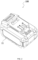
FIG. 2 is a perspective view of a battery pack according to an example of the present application; -
FIG. 3 is an exploded view of the battery pack inFIG. 2 ; -
FIG. 4 is a perspective view of a battery pack according to an example of the present application; -
FIG. 5 is an exploded view of the battery pack inFIG. 4 ; -
FIG. 6 is a perspective view of a battery pack according to an example of the present application; and -
FIG. 7 is an exploded view of the battery pack inFIG. 6 . - Before any examples of this application are explained in detail, it is to be understood that this application is not limited to its application to the structural details and the arrangement of components set forth in the following description or illustrated in the above drawings.
- In this application, the terms "comprising", "including", "having" or any other variation thereof are intended to cover an inclusive inclusion such that a process, method, article or device comprising a series of elements includes not only those series of elements, but also other elements not expressly listed, or elements inherent in the process, method, article, or device. Without further limitations, an element defined by the phrase "comprising a ..." does not preclude the presence of additional identical elements in the process, method, article, or device comprising that element.
- In this application, the term "and/or" is a kind of association relationship describing the relationship between associated objects, which means that there can be three kinds of relationships. For example, A and/or B can indicate that A exists alone, A and B exist simultaneously, and B exists alone. In addition, the character "/" in this application generally indicates that the contextual associated objects belong to an "and/or" relationship.
- In this application, the terms "connection", "combination", "coupling" and "installation" may be direct connection, combination, coupling or installation, and may also be indirect connection, combination, coupling or installation. Among them, for example, direct connection means that two members or assemblies are connected together without intermediaries, and indirect connection means that two members or assemblies are respectively connected with at least one intermediate members and the two members or assemblies are connected by the at least one intermediate members. In addition, "connection" and "coupling" are not limited to physical or mechanical connections or couplings, and may include electrical connections or couplings.
- In this application, it is to be understood by those skilled in the art that a relative term (such as "about", "approximately", and "substantially") used in conjunction with quantity or condition includes a stated value and has a meaning dictated by the context. For example, the relative term includes at least a degree of error associated with the measurement of a particular value, a tolerance caused by manufacturing, assembly, and use associated with the particular value, and the like. Such relative term should also be considered as disclosing the range defined by the absolute values of the two endpoints. The relative term may refer to plus or minus of a certain percentage (such as 1%, 5%, 10%, or more) of an indicated value. A value that did not use the relative term should also be disclosed as a particular value with a tolerance. In addition, "substantially" when expressing a relative angular position relationship (for example, substantially parallel, substantially perpendicular), may refer to adding or subtracting a certain degree (such as 1 degree, 5 degrees, 10 degrees or more) to the indicated angle.
- In this application, those skilled in the art will understand that a function performed by an assembly may be performed by one assembly, multiple assemblies, one member, or multiple members. Likewise, a function performed by a member may be performed by one member, an assembly, or a combination of members.
- In this application, the terms "up", "down", "left", "right", "front", and "rear" " and other directional words are described based on the orientation or positional relationship shown in the drawings, and should not be understood as limitations to the examples of this application. In addition, in this context, it also needs to be understood that when it is mentioned that an element is connected "above" or "under" another element, it can not only be directly connected "above" or "under" the other element, but can also be indirectly connected "above" or "under" the other element through an intermediate element. It should also be understood that orientation words such as upper side, lower side, left side, right side, front side, and rear side do not only represent perfect orientations, but can also be understood as lateral orientations. For example, lower side may include directly below, bottom left, bottom right, front bottom, and rear bottom.
- In this application, the terms "controller", "processor", "central processor", "CPU" and "MCU" are interchangeable. Where a unit "controller", "processor", "central processing", "CPU", or "MCU" is used to perform a specific function, the specific function may be implemented by a single aforementioned unit or a plurality of the aforementioned unit.
- In this application, the term "device", "module" or "unit" may be implemented in the form of hardware or software to achieve specific functions.
- In this application, the terms "computing", "judging", "controlling", "determining", "recognizing" and the like refer to the operations and processes of a computer system or similar electronic computing device (e.g., controller, processor, etc.).
- Referring to a
power tool 10 shown inFIG. 1 , thepower tool 10 includes atool body 101, anelectric motor 102, and apower interface 103. Thepower interface 103 may be connected to abattery pack 104. - The
battery pack 104 involved here can be adapted to various types ofpower tools 10. For example, thepower tool 10 may be a handheld power tool, such as a drill, a hedge trimmer, or a sander. Alternatively, thepower tool 10 may be a table tool, such as a table saw or a miter saw. Alternatively, thepower tool 10 may be a push power tool, such as a push mower or a push snow thrower. Alternatively, thepower tool 10 may be a riding power tool, such as a riding mower, a riding vehicle, or an all-terrain vehicle. Alternatively, thepower tool 10 may be a robotic tool, such as a robotic mower or a robotic snow thrower. In some examples, thepower tool 10 may be an electric drill, an electric lamp, an electric vehicle, or the like. In some examples, thepower tool 10 may be a garden tool, such as a hedge trimmer, a blower, a mower, or a chain saw. Alternatively, thepower tool 10 may be a decorating tool, such as a screwdriver, a nail gun, a circular saw, or a sander. In some examples, thepower tool 10 may be a vegetation care tool, such as a grass trimmer, a mower, a hedge trimmer, or a chain saw. Alternatively, thepower tool 10 may be a cleaning tool, such as a blower, a snow thrower, or a washer. Alternatively, thepower tool 10 may be a drill-like tool, such as a drill, a screwdriver, a wrench, or an electric hammer. Alternatively, thepower tool 10 may be a saw-like tool, such as a reciprocating saw, a jigsaw, or a circular saw. Alternatively, thepower tool 10 may be a table tool, such as a table saw, a miter saw, a metal cutter, or an electric router. Alternatively, thepower tool 10 may be a sanding tool, such as an angle grinder or a sander. Alternatively, thepower tool 10 may be another tool, such as a lamp or a fan. - The
battery pack 104 in the example of the present application may be a liquid lithium-ion battery with a polymer housing, a pouch battery, or a hard pack battery using hard materials as the battery housing. For example, the housing of the hard pack battery may be made of plastic, steel, or aluminum. The battery cells in thebattery pack 104 may be cylindrical cells, square cells, or sheet cells. Thebattery pack 104 may be a lithium iron phosphate battery, a ternary lithium battery, a sodium-ion battery, or the like. Thebattery pack 104 inFIG. 1 may include the battery pack in the examples below. - A
battery pack 100 shown inFIG. 2 is a pouch battery. Thebattery pack 100 includes ahousing assembly 11, abattery cell module 12 disposed in thehousing assembly 11, acircuit board 13, and abattery terminal 14. Thebattery cell module 12 may include at leastmultiple battery cells 121, which may also be referred to as cell units or cells. A connector (not shown) is disposed between at least twobattery cells 121, and the connector can electrically connect at least twobattery cells 121. - As shown in
FIG. 3 , thehousing assembly 11 may include anupper housing 111 and alower housing 112. After being assembled, theupper housing 111 and thelower housing 112 can form an accommodation space for fixing and accommodating thebattery cell module 12 and thecircuit board 13. Abattery interface 113 is formed on the surface of theupper housing 111 or thelower housing 112, and thebattery terminal 14 is located in thebattery interface 113. Thebattery terminal 14 is electrically connected to thebattery cells 121, and thebattery terminal 14 includes at least a positive battery terminal and a negative battery terminal and may further include a communication terminal. Thebattery pack 100 may be electrically connected to a tool terminal on the power tool housing through thebattery terminal 14 to transmit electric power or communicate data between thebattery pack 100 and the power tool. In this example, thebattery terminal 14 is disposed on thecircuit board 13. - The
circuit board 13 may also be provided with other electronic components, such as a battery management chip that manages the charging and discharging of thebattery pack 100. In an example, thecircuit board 13 and the electronic components or thebattery terminal 14 disposed on thecircuit board 13 may be electrically connected through wires.Different battery cells 121 may be electrically connected using cell connectors or wires. Any welding manner such as spot welding, line welding, surface welding, ultrasonic welding, or laser spot welding may be adopted between thebattery cells 121 and the wires, thecircuit board 13 and the electronic components, or thebattery cells 121. In this example, the battery management chip may also be referred to as a battery management module and may include one or more electronic components or integrated management chips, such as microcontroller units (MCUs). - In this example, the
battery cell module 12 may further include acell holder 122 for supporting themultiple battery cells 121. In an example, thecell holder 122 is disposed at two ends of a cell group formed by themultiple battery cells 121. In an example, thecell holder 122 may form multiple support cavities, and each support cavity can accommodate at least onebattery cell 121. In an example, thewhole cell holder 122 is accommodated in the accommodation space formed by thehousing assembly 11. In an example, part of the external surface of thecell holder 122 is exposed. - Generally, when the battery pack is discharged during normal use, the structural strength of the battery pack is sufficient to support the application in different working conditions or scenarios. However, under special circumstances, the impact load causes damage to the surface of the impacted structure and the structure and may even cause the structure to completely lose functionality, causing secondary damage.
- For example, when the battery pack accidentally falls from a high place, or a user inadvertently uses the battery pack as a hammer, the housing assembly of the battery pack cannot withstand a relatively large impact force, causing the housing assembly to be damaged. In serious cases, dangerous situations such as burning or explosion of the battery cells inside the battery pack may occur.
- To solve the preceding problems, in the present application, the impact toughness of the battery pack is enhanced by enhancing at least the impact resistance of the housing assembly.
- In an example, a polyurea coating may be applied to at least a portion of the housing assembly. The polyurea coating is specifically a polyurea resin coating, may also be referred to as a polyurea elastomer, and relates to an efficient coating protection technology. Polyurea is produced by a rapid polymerization reaction between an isocyanate component (-NCO) and an amino component (-NH2). The advantages of convenient construction, lightweight, and high impact energy absorption are ensured.
- In this example, the polyurea coating may be a colloidal material formulated with a high-strength anchoring agent, an accelerator, and some auxiliary materials in a certain proportion. The coating is cured quickly after being sprayed on the surface of an object. In fact, the curing time for the polyurea coating on the housing assembly may be as small as a few seconds, a few minutes, more than ten and less than twenty minutes, or more than twenty and less than thirty minutes. The curing time for the polyurea coating is controllable. Generally, the curing time for polyurea may be adjusted by adjusting the proportion of the anchoring agent. In some examples, the curing time for the polyurea coating is also related to the ambient temperature of the coating spraying and the like. The user may adjust the curing time of the polyurea coating by adjusting the ambient temperature.
- In this example, the curing time for the polyurea coating is less than equal to 20 min. In an example, the curing time for the polyurea coating is less than equal to 10 min. In an example, the curing time for the polyurea coating is less than equal to 5 min. In an example, the curing time for the polyurea coating is less than or equal to 1 min. For example, the curing time for the polyurea coating may be 5s, 10s, 20s, 30s, 40s, 50s, 60s, or the like. In this example, the curing time for the polyurea on the housing may be adjusted to be shorter, for example, 5s, to prevent the following: after non-solid polyurea is sprayed at the corners of the housing assembly, the polyurea flows due to the influence of gravity before being cured, resulting in a relatively thin polyurea coating at the corners or even the completely loss of polyurea at the corners. It is to be understood that since the curing time for the polyurea coating on the housing assembly is very short, the non-solid polyurea may be cured quickly after being sprayed on the housing and thus may be sprayed evenly on the surface of the housing without the affect of external factors such as gravity or tension.
- In this example, the method in which the polyurea coating is applied to the housing assembly is not limited and may be spraying, vapor deposition, or another method. In an example, the thickness of the polyurea coating on the housing assembly is less than or equal to 5 mm. In an example, the thickness of the polyurea coating on the housing assembly is less than or equal to 3 mm. In an example, the thickness of the polyurea coating on the housing assembly is less than or equal to 2 mm. In an example, the thickness of the polyurea coating on the housing assembly is less than or equal to 1.5 mm. In an example, the thickness of the polyurea coating on the housing assembly is less than or equal to 1 mm. For example, the thickness of the polyurea coating on the housing assembly may be 3 mm, 2 mm, 2.5 mm, 2 mm, 1.5 mm, 1 mm, or the like.
- In some examples, the polyurea coating is evenly applied to the external surface of the housing assembly to form a strong protective layer, which can play a certain waterproof role and have certain wear-resistant properties. In some examples, the polyurea coating is applied to part of the housing assembly, for example, the landing position of the falling battery pack or the habitual knocking position of the user. These positions may be obtained through multiple falling experiments or knocking experiments. In some examples, the polyurea coating may be evenly applied to the internal surface of the housing assembly.
- In some examples, the polyurea coating may be applied to the battery cell module, the circuit board, or the connector connecting at least two battery cells. The polyurea coating may be applied to the battery cells of the battery cell module or the cell holder. It is to be understood that the polyurea coating applied to the circuit board, the battery terminal, or the battery cells can not only enhance the strength of the coating part but also play a role of electrical insulation.
- In an example, the circuit board includes a substrate, which may also be referred to as a substrate board. The circuit board may further include an electronic component supported on the substrate and a base coating applied to the electronic component. In this example, the polyurea coating may be applied to the base coating.
- The thickness of the polyurea coating applied to different parts of the battery pack may be the same or different. In an example, the thickness of the polyurea coating applied to the housing assembly is greater than the thickness of the coating applied to the circuit board, the battery terminal, or the battery cell module. For example, the thickness of the polyurea coating applied to the housing may be 1 mm, while the thickness of the polyurea coating applied to the circuit board may be 10 µm.
- In other examples, the polyurea coating may be sprayed on the power tool to which the battery pack is adapted, for example, on the power tool housing.
- The polyurea coating in the present application may be sprayed on a
housing 21 of a basicallycuboid battery pack 200 shown inFIGS. 4 and5 , abattery cell module 22 in thehousing 21, or ahandle 23. Thehousing 21 includes anupper cover 211 and abottom compartment 212. Thebottom compartment 212 is configured to be a cuboid cavity with an upper opening, and thebattery cell module 22 is accommodated in thebottom compartment 212. Thebattery cell module 22 includes at least acell holder 221,multiple battery cells 222, acircuit board 223 electrically connected to thebattery cells 222, and abattery terminal 224 electrically coupled to thecircuit board 223. - The polyurea coating in the present application may be sprayed on a
housing 31 of abattery pack 300 shown inFIGS. 6 and7 . Alternatively, the polyurea coating is sprayed on other parts of thebattery pack 300. Thehousing 31 includes anupper end cover 311, alower end cover 312, and aside end surface 313. In this example, most of acell holder 33 of abattery cell module 32 in thebattery pack 300 are exposed to the outside, forming thehousing 31 of thebattery pack 300. That is to say, the outer portion of thecell holder 33, theupper end cover 311, thelower end cover 312, and theside end surface 313 form the housing of thebattery pack 300. Thebattery pack 300 further includes abattery terminal 34 located in theside end surface 313. - The specific structures of the
battery pack 200 and thebattery pack 300 are not introduced too much here. In some examples, the polyurea coating may be sprayed on at least part of the structure of another type of battery pack, which is not introduced one by one here. - In some examples, the polyurea coating may be applied to the body of the power tool, for example, to the power tool housing, an electric motor housing in the power tool, or a tool accessory on the power tool, such as a drill bit or a bit.
- The basic principles, main features, and advantages of this application are shown and described above. It is to be understood by those skilled in the art that the aforementioned examples do not limit the present application in any form, and all technical solutions obtained through equivalent substitutions or equivalent transformations fall within the scope of the present application.
Claims (11)
- A battery pack (100, 200, 300) for a power tool (10), comprising:a housing assembly (11);a battery cell module (12, 22, 32) disposed in the housing assembly and comprising at least a plurality of battery cells (121, 222);a circuit board (13, 223) disposed in the housing assembly and electrically connected to the plurality of battery cells;a battery terminal(14, 224, 34) electrically connected to the plurality of battery cells to connect the plurality of battery cells to the power tool for transmitting electric power; anda polyurea coating applied to at least part of the housing assembly.
- The battery pack of claim 1, wherein the polyurea coating is applied to at least one of the battery cell module, the circuit board, and a connector connecting the plurality of battery cells.
- The battery pack of claim 1, wherein the battery cell module further comprises a cell holder (122, 221, 33) configured to support the plurality of battery cells, and the polyurea coating is applied to the cell holder and/or at least one of the plurality of battery cells.
- The battery pack of claim 3, wherein the cell holder comprises a portion that is exposed after the battery pack is assembled, and the polyurea coating is applied to an external surface of the exposed cell holder.
- The battery pack of claim 1, wherein the polyurea coating is applied to at least part of an external surface and/or at least part of an internal surface of the housing assembly.
- The battery pack of claim 1, wherein a thickness of the polyurea coating applied to the at least part of the housing assembly is less than or equal to 5 mm.
- The battery pack of claim 1, wherein curing time for the polyurea coating is controllable.
- The battery pack of claim 1, wherein curing time for the polyurea coating is less than equal to 20 min.
- The battery pack of claim 1, wherein the circuit board comprises a substrate, an electronic component supported on the substrate, and a base coating applied to at least the electronic component, wherein the polyurea coating is applied to the base coating.
- The battery pack of claim 9, wherein the base coating is applied to the substrate and the electronic component.
- A power tool (10), comprising:a tool body (101);an electric motor (102) disposed in the tool body;a power interface (103); anda battery pack (100, 200, 300) of any one of the claims 1-10;wherein the power interface is configured to be connected to the battery pack for supplying power to the electric motor.
Applications Claiming Priority (2)
| Application Number | Priority Date | Filing Date | Title |
|---|---|---|---|
| CN202310206689 | 2023-03-06 | ||
| CN202311677651.XA CN118596090A (en) | 2023-03-06 | 2023-12-08 | Power tools and battery packs |
Publications (1)
| Publication Number | Publication Date |
|---|---|
| EP4429003A1 true EP4429003A1 (en) | 2024-09-11 |
Family
ID=89722949
Family Applications (1)
| Application Number | Title | Priority Date | Filing Date |
|---|---|---|---|
| EP24153811.5A Pending EP4429003A1 (en) | 2023-03-06 | 2024-01-25 | Power tool and battery pack |
Country Status (2)
| Country | Link |
|---|---|
| US (1) | US20240304922A1 (en) |
| EP (1) | EP4429003A1 (en) |
Families Citing this family (2)
| Publication number | Priority date | Publication date | Assignee | Title |
|---|---|---|---|---|
| USD1122188S1 (en) * | 2025-04-18 | 2026-04-14 | Shenzhen Jinjunye Electronics Co., Ltd. | Power tool battery |
| USD1122189S1 (en) * | 2025-05-12 | 2026-04-14 | Shenzhen Jinjunye Electronics Co., Ltd. | Power tool battery |
Citations (4)
| Publication number | Priority date | Publication date | Assignee | Title |
|---|---|---|---|---|
| US20150140411A1 (en) * | 2013-11-20 | 2015-05-21 | The Bergquist Company | Battery Cell Coatings |
| CN109926290A (en) * | 2017-12-15 | 2019-06-25 | 上海电巴新能源科技有限公司 | Battery case surface protecting layer and process for protecting |
| US20200321576A1 (en) * | 2019-04-05 | 2020-10-08 | Makita Corporation | Battery pack |
| CN112993442A (en) * | 2021-04-30 | 2021-06-18 | 嘉兴模度新能源有限公司 | Super module |
-
2024
- 2024-01-25 EP EP24153811.5A patent/EP4429003A1/en active Pending
- 2024-01-25 US US18/422,679 patent/US20240304922A1/en active Pending
Patent Citations (4)
| Publication number | Priority date | Publication date | Assignee | Title |
|---|---|---|---|---|
| US20150140411A1 (en) * | 2013-11-20 | 2015-05-21 | The Bergquist Company | Battery Cell Coatings |
| CN109926290A (en) * | 2017-12-15 | 2019-06-25 | 上海电巴新能源科技有限公司 | Battery case surface protecting layer and process for protecting |
| US20200321576A1 (en) * | 2019-04-05 | 2020-10-08 | Makita Corporation | Battery pack |
| CN112993442A (en) * | 2021-04-30 | 2021-06-18 | 嘉兴模度新能源有限公司 | Super module |
Also Published As
| Publication number | Publication date |
|---|---|
| US20240304922A1 (en) | 2024-09-12 |
Similar Documents
| Publication | Publication Date | Title |
|---|---|---|
| EP4429003A1 (en) | Power tool and battery pack | |
| US20240213600A1 (en) | Portable power tool, battery pack, and cell configurations for same | |
| AU2020101753A4 (en) | Battery pack including staggered battery pack terminals | |
| US20180198292A1 (en) | Universal Power Tool Battery Pack And Recharging System | |
| US7492125B2 (en) | Power tools, battery chargers and batteries | |
| US11399461B2 (en) | Handle assembly for garden tool and garden tool having same | |
| US20100190052A1 (en) | Battery pack with high and low current discharge terminals | |
| US20230282920A1 (en) | Battery pack with double shear connection | |
| US12418069B2 (en) | Power tool and battery pack | |
| US20250262959A1 (en) | Adapter and charging system including the adapter | |
| CN118596090A (en) | Power tools and battery packs | |
| EP4574343A1 (en) | Power tool | |
| US20250364610A1 (en) | Battery pack for powering a power tool | |
| EP4539229A1 (en) | Battery pack | |
| US20250167630A1 (en) | Power tool and battery pack thereof | |
| EP4687183A1 (en) | Battery pack | |
| US20250105419A1 (en) | Adapter, electric device, and system | |
| WO2024099189A1 (en) | Battery pack and charging combination | |
| WO2024212178A1 (en) | Battery pack | |
| CN219832864U (en) | Battery pack and electric tool | |
| US20250132591A1 (en) | Battery pack configured to be capable of supplying power to a power tool | |
| CN223871495U (en) | Battery devices and electrical equipment | |
| US20220320667A1 (en) | Cordless Device and System | |
| AU2024398148A1 (en) | Charger | |
| CN116722211A (en) | Solid-state battery pack and electric tool for building |
Legal Events
| Date | Code | Title | Description |
|---|---|---|---|
| PUAI | Public reference made under article 153(3) epc to a published international application that has entered the european phase |
Free format text: ORIGINAL CODE: 0009012 |
|
| STAA | Information on the status of an ep patent application or granted ep patent |
Free format text: STATUS: THE APPLICATION HAS BEEN PUBLISHED |
|
| AK | Designated contracting states |
Kind code of ref document: A1 Designated state(s): AL AT BE BG CH CY CZ DE DK EE ES FI FR GB GR HR HU IE IS IT LI LT LU LV MC ME MK MT NL NO PL PT RO RS SE SI SK SM TR |
|
| STAA | Information on the status of an ep patent application or granted ep patent |
Free format text: STATUS: REQUEST FOR EXAMINATION WAS MADE |
|
| 17P | Request for examination filed |
Effective date: 20250219 |
|
| STAA | Information on the status of an ep patent application or granted ep patent |
Free format text: STATUS: EXAMINATION IS IN PROGRESS |
|
| 17Q | First examination report despatched |
Effective date: 20251027 |
|
| GRAP | Despatch of communication of intention to grant a patent |
Free format text: ORIGINAL CODE: EPIDOSNIGR1 |
|
| STAA | Information on the status of an ep patent application or granted ep patent |
Free format text: STATUS: GRANT OF PATENT IS INTENDED |
|
| GRAS | Grant fee paid |
Free format text: ORIGINAL CODE: EPIDOSNIGR3 |
|
| GRAA | (expected) grant |
Free format text: ORIGINAL CODE: 0009210 |
|
| STAA | Information on the status of an ep patent application or granted ep patent |
Free format text: STATUS: THE PATENT HAS BEEN GRANTED |