EP4428974A1 - Electrode assembly manufacturing apparatus and manufacturing method of the same - Google Patents
Electrode assembly manufacturing apparatus and manufacturing method of the same Download PDFInfo
- Publication number
- EP4428974A1 EP4428974A1 EP24158634.6A EP24158634A EP4428974A1 EP 4428974 A1 EP4428974 A1 EP 4428974A1 EP 24158634 A EP24158634 A EP 24158634A EP 4428974 A1 EP4428974 A1 EP 4428974A1
- Authority
- EP
- European Patent Office
- Prior art keywords
- electrode
- separator
- jelly roll
- header
- motor
- Prior art date
- Legal status (The legal status is an assumption and is not a legal conclusion. Google has not performed a legal analysis and makes no representation as to the accuracy of the status listed.)
- Pending
Links
Images





Classifications
-
- H—ELECTRICITY
- H01—ELECTRIC ELEMENTS
- H01M—PROCESSES OR MEANS, e.g. BATTERIES, FOR THE DIRECT CONVERSION OF CHEMICAL ENERGY INTO ELECTRICAL ENERGY
- H01M10/00—Secondary cells; Manufacture thereof
- H01M10/04—Construction or manufacture in general
- H01M10/0404—Machines for assembling batteries
-
- H—ELECTRICITY
- H01—ELECTRIC ELEMENTS
- H01M—PROCESSES OR MEANS, e.g. BATTERIES, FOR THE DIRECT CONVERSION OF CHEMICAL ENERGY INTO ELECTRICAL ENERGY
- H01M10/00—Secondary cells; Manufacture thereof
- H01M10/04—Construction or manufacture in general
- H01M10/0431—Cells with wound or folded electrodes
-
- H—ELECTRICITY
- H01—ELECTRIC ELEMENTS
- H01M—PROCESSES OR MEANS, e.g. BATTERIES, FOR THE DIRECT CONVERSION OF CHEMICAL ENERGY INTO ELECTRICAL ENERGY
- H01M10/00—Secondary cells; Manufacture thereof
- H01M10/04—Construction or manufacture in general
- H01M10/0404—Machines for assembling batteries
- H01M10/0409—Machines for assembling batteries for cells with wound electrodes
-
- H—ELECTRICITY
- H01—ELECTRIC ELEMENTS
- H01M—PROCESSES OR MEANS, e.g. BATTERIES, FOR THE DIRECT CONVERSION OF CHEMICAL ENERGY INTO ELECTRICAL ENERGY
- H01M10/00—Secondary cells; Manufacture thereof
- H01M10/05—Accumulators with non-aqueous electrolyte
- H01M10/058—Construction or manufacture
- H01M10/0583—Construction or manufacture of accumulators with folded construction elements except wound ones, i.e. folded positive or negative electrodes or separators, e.g. with "Z"-shaped electrodes or separators
-
- B—PERFORMING OPERATIONS; TRANSPORTING
- B65—CONVEYING; PACKING; STORING; HANDLING THIN OR FILAMENTARY MATERIAL
- B65H—HANDLING THIN OR FILAMENTARY MATERIAL, e.g. SHEETS, WEBS, CABLES
- B65H45/00—Folding thin material
- B65H45/02—Folding limp material without application of pressure to define or form crease lines
- B65H45/06—Folding webs
- B65H45/10—Folding webs transversely
- B65H45/101—Folding webs transversely in combination with laying, i.e. forming a zig-zag pile
- B65H45/107—Folding webs transversely in combination with laying, i.e. forming a zig-zag pile by means of swinging or reciprocating guide bars
-
- B—PERFORMING OPERATIONS; TRANSPORTING
- B65—CONVEYING; PACKING; STORING; HANDLING THIN OR FILAMENTARY MATERIAL
- B65H—HANDLING THIN OR FILAMENTARY MATERIAL, e.g. SHEETS, WEBS, CABLES
- B65H5/00—Feeding articles separated from piles; Feeding articles to machines
- B65H5/08—Feeding articles separated from piles; Feeding articles to machines by grippers, e.g. suction grippers
-
- H—ELECTRICITY
- H01—ELECTRIC ELEMENTS
- H01M—PROCESSES OR MEANS, e.g. BATTERIES, FOR THE DIRECT CONVERSION OF CHEMICAL ENERGY INTO ELECTRICAL ENERGY
- H01M10/00—Secondary cells; Manufacture thereof
- H01M10/04—Construction or manufacture in general
- H01M10/0459—Cells or batteries with folded separator between plate-like electrodes
-
- H—ELECTRICITY
- H01—ELECTRIC ELEMENTS
- H01M—PROCESSES OR MEANS, e.g. BATTERIES, FOR THE DIRECT CONVERSION OF CHEMICAL ENERGY INTO ELECTRICAL ENERGY
- H01M10/00—Secondary cells; Manufacture thereof
- H01M10/05—Accumulators with non-aqueous electrolyte
- H01M10/052—Li-accumulators
- H01M10/0525—Rocking-chair batteries, i.e. batteries with lithium insertion or intercalation in both electrodes; Lithium-ion batteries
-
- B—PERFORMING OPERATIONS; TRANSPORTING
- B65—CONVEYING; PACKING; STORING; HANDLING THIN OR FILAMENTARY MATERIAL
- B65H—HANDLING THIN OR FILAMENTARY MATERIAL, e.g. SHEETS, WEBS, CABLES
- B65H2701/00—Handled material; Storage means
- B65H2701/10—Handled articles or webs
- B65H2701/19—Specific article or web
-
- H—ELECTRICITY
- H01—ELECTRIC ELEMENTS
- H01M—PROCESSES OR MEANS, e.g. BATTERIES, FOR THE DIRECT CONVERSION OF CHEMICAL ENERGY INTO ELECTRICAL ENERGY
- H01M10/00—Secondary cells; Manufacture thereof
- H01M10/05—Accumulators with non-aqueous electrolyte
- H01M10/052—Li-accumulators
-
- Y—GENERAL TAGGING OF NEW TECHNOLOGICAL DEVELOPMENTS; GENERAL TAGGING OF CROSS-SECTIONAL TECHNOLOGIES SPANNING OVER SEVERAL SECTIONS OF THE IPC; TECHNICAL SUBJECTS COVERED BY FORMER USPC CROSS-REFERENCE ART COLLECTIONS [XRACs] AND DIGESTS
- Y02—TECHNOLOGIES OR APPLICATIONS FOR MITIGATION OR ADAPTATION AGAINST CLIMATE CHANGE
- Y02E—REDUCTION OF GREENHOUSE GAS [GHG] EMISSIONS, RELATED TO ENERGY GENERATION, TRANSMISSION OR DISTRIBUTION
- Y02E60/00—Enabling technologies; Technologies with a potential or indirect contribution to GHG emissions mitigation
- Y02E60/10—Energy storage using batteries
-
- Y—GENERAL TAGGING OF NEW TECHNOLOGICAL DEVELOPMENTS; GENERAL TAGGING OF CROSS-SECTIONAL TECHNOLOGIES SPANNING OVER SEVERAL SECTIONS OF THE IPC; TECHNICAL SUBJECTS COVERED BY FORMER USPC CROSS-REFERENCE ART COLLECTIONS [XRACs] AND DIGESTS
- Y02—TECHNOLOGIES OR APPLICATIONS FOR MITIGATION OR ADAPTATION AGAINST CLIMATE CHANGE
- Y02P—CLIMATE CHANGE MITIGATION TECHNOLOGIES IN THE PRODUCTION OR PROCESSING OF GOODS
- Y02P70/00—Climate change mitigation technologies in the production process for final industrial or consumer products
- Y02P70/50—Manufacturing or production processes characterised by the final manufactured product
Definitions
- the present invention relates to an electrode assembly manufacturing apparatus and a manufacturing method of the same.
- An electrode assembly mounted in secondary batteries is a power generation element composed of a structure in which a cathode, an anode, and a separator interposed therebetween are stacked. Electrode assemblies are classified into a jelly roll type formed by interposing a separator between a cathode and an anode in the form of a long sheet coated with an active material and winding the same; and a stack type formed by stacking multiple cathodes and anodes of a predetermined size with a separator interposed therebetween.
- a stack type electrode assembly had a problem that stacking cathodes, anodes, and separators take much time. To solve this problem, an attempt was made to increase efficiency by moving a table on which electrode assemblies was stacked, but as the stack continued to move, there was a problem that the electrodes deviated from their right positions and stability deteriorated.
- a problem that the present disclosure aims to solve is to provide an apparatus and a method for manufacturing an electrode assembly that can prevent electrodes from deviating from their right positions and increase productivity when stacking electrodes and separators in a stacked type.
- the battery cell of the present disclosure can be widely applied in the field of green technology, such as electric vehicles, battery charging stations, solar power generation, and wind power generation using batteries.
- the battery cell of the present disclosure can be used in eco-friendly electric vehicles, hybrid vehicles, etc. to prevent climate change by suppressing air pollution and greenhouse gas emissions.
- An electrode assembly manufacturing apparatus may include: a first table on which a first half jelly roll is stacked; a second table on which a second half jelly roll is stacked; a separator disposed on the first table and the second table; a first separator reel unwinding the separator in a direction to the first table; a second separator reel unwinding the separator in a direction to the second table; an electrode header providing a first electrode and a second electrode to the first table and the second table; a first motor moving the separator in a direction for covering the first electrode and the second electrode provided on the first table; a second motor moving the separator in a direction for covering the first electrode and the second electrode provided on the second table; and an assembly header providing the second electrode between the first half jelly roll and the second half jelly roll.
- a first table and a second table may be physically connected.
- a first table may include a first leg
- a second table may include a second leg, so that the first leg and the second leg may be formed to be perpendicular.
- a first motor may move a separator by repeatedly moving horizontally with a first table.
- a second motor may move a separator by repeatedly moving horizontally with a second table.
- an electrode header may include a first electrode header disposing a first electrode on a first table and a second table.
- an electrode header may include a second electrode header disposing a second electrode on a first table and a second table.
- an assembly header may include a first assembly header surrounding and moving a first half jelly roll.
- an assembly header may include a second assembly header surrounding and moving a second half jelly roll.
- an assembly header may include a third assembly header providing a second electrode.
- the electrode assembly manufacturing apparatus may include a stacking header surrounding a first half jelly roll, a second half jelly roll, and a second electrode with a separator.
- An electrode assembly manufacturing method may include: a step in which a separator is unwound from a first separator reel in a direction to a first table and a separator is unwound from a second separator reel in a direction to a second table; a step in which a first separator is disposed on the first table and a second separator is disposed on the second table; a step in which a first electrode header disposes a first electrode on the first table and the second table; a step in which a first motor moves a separator on the first table and a second motor moves a separator on the second table; a step in which a first electrode header disposes a second electrode on the first table and the second table; a step in which an assembly header provides the second electrode between a first half jelly roll stacked on the first table and a second half jelly roll stacked on the second table; and a step in which a stacking header surrounds the circumference of the stacked half jelly roll with a separator.
- the present invention can increase the productivity of electrode assembly by improving the speed of stacking a cathode, an anode, and a separator.
- the present invention can prevent the problem that an electrode deviates from the right position to reduce the defect rate because a table on which stacks are manufactured is fixed.
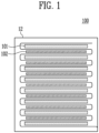
- FIG. 1 shows a diagram of an electrode assembly 100 manufactured according to an embodiment of the present invention.
- An electrode assembly 100 includes a cathode, an anode, and a separator disposed between the cathode and the anode.
- a separator 12 may be interposed between a first electrode 101 and a second electrode 102 to manufacture an electrode assembly.
- a first electrode 101 and a second electrode 102 may be a cathode or an anode.
- a first electrode 101 and A second electrode 102 refer to different electrodes. For example, when a first electrode 101 is a cathode, a second electrode 102 is an anode; and when a first electrode 101 is an anode, a second electrode 102 refers to a cathode.
- a cathode and an anode may include a current collector and an active material layer disposed on the current collector.
- a cathode may include a cathode current collector and a cathode active material layer
- an anode may include an anode current collector and an anode active material layer.
- a current collector may include a known conductive material to an extent that it does not cause a chemical reaction within a lithium secondary battery.
- a current collector may include any one of stainless steel, nickel (Ni), aluminum (Al), titanium (Ti), copper (Cu), and alloys thereof, and may be provided in various forms such as film, sheet, and foil.
- An active material layer includes an active material.
- a cathode active material layer may include a cathode active material
- an anode active material layer may include an anode active material.
- a cathode active material may be a material which lithium ions may be inserted to and extracted from.
- a cathode active material may be a lithium metal oxide.
- a cathode active material may be one of a lithium manganese oxide, a lithium nickel oxide, a lithium cobalt oxide, a lithium nickel manganese oxide, a lithium nickel cobalt manganese oxide, a lithium nickel cobalt aluminum oxide, a lithium iron phosphate-based compound, a lithium manganese phosphate-based compound, a lithium cobalt phosphate-based compound and a lithium vanadium phosphate-based compound.
- An anode active material may be a material which lithium ions may be inserted to and extracted from.
- an anode active material may be any one of carbon-based materials such as crystalline carbon, amorphous carbon, carbon composite, and carbon fiber, a lithium alloy, silicon (Si), and tin (Sn).
- an anode active material may be natural graphite or artificial graphite, but is not limited to a specific example.
- a cathode and an anode may each further include a binder and a conductive material.
- a binder may improve mechanical stability by mediating a bond between a current collector and an active material layer.
- a binder may be an organic binder or an aqueous binder.
- an organic binder may be one of vinylidene fluoride-hexafluoropropylene copolymer (PVDF-co-HFP), polyvinylidene fluoride (PVDF), polyacrylonitrile, and polymethylmethacrylate
- an aqueous binder may be styrene-butadiene rubber (SBR), but they are not limited thereto.
- a conductive material may improve electrical conductivity of a secondary battery.
- a conductive material may include a metal-based material.
- a conductive material may include a conventional carbon-based conductive material.
- a conductive material may include any one of graphite, carbon black, graphene, and carbon nanotubes, and preferably, a conductive material may include carbon nanotubes.
- a separator is disposed between a cathode and an anode.
- a separator may be configured to prevent an electrical short between a cathode and an anode and to generate a flow of ions.
- a separator may include a porous polymer film or a porous nonwoven fabric.
- a porous polymer film may be configured as a single layer or a multi-layer including a polyolefin polymer such as an ethylene polymer, a propylene polymer, an ethylene/butene copolymer, an ethylene/hexene copolymer, and an ethylene/methacrylate copolymer.
- a porous nonwoven fabric may include glass fibers of a high melting point and polyethylene terephthalate fibers.
- a separator may be a ceramic coated separator including ceramic.
- a first half jelly roll 110 may refer to a stack produced by stacking a first electrode 101, a second electrode 102, and a separator 12 on a first table 21; and a second half jelly roll 120 may refer to a stack produced by stacking a first electrode 101, a second electrode 102, and a separator 12 on a second table 22.
- a first table 21 and a second table 22 are places where a first half jelly roll 110 and a second half jelly roll 110 are manufactured, as a first electrode 101, a second electrode 102, and a separator 12 are seated and stacked on the upper surfaces thereof.
- a first table 21 and a second table 22 may preferably include a flat cross-section so that a first half jelly roll 110 and a second half jelly roll 120 may be stacked, respectively.
- a separator 12 may be unwound from a first separator reel 10 and a second separator reel 11 and disposed on a first table 21 and a second table 22.
- a separator 12 unwound from a first separator reel 10 and a second separator reel 11 may be formed as one continuous separator 12.
- Both ends of one separator 12 may be wound around a first separator reel 10 and a second separator reel 11, respectively.
- Preferably, half of a separator may be wound around a first separator reel 10, and the other half may be wound around a second separator reel 11.
- a separator 12 disposed on a first table 21 may be unwound from a first separator reel 10.
- a separator 12 disposed on a second table 22 may be unwound from a second separator reel 11. Through this, a separator 12 may be unwound from each of a first separator reel 10 and a second separator reel 11 so that stacking can be quickly performed.
- a first table 21 may include a first leg 23, and a second table 22 may include a second leg 24.
- a first leg 23 may be connected to a first table 21 and may change the position of a first table 21. For example, a first leg 23 may move a first table 21 so that the first table 21 may be horizontal or inclined with respect to the ground.
- a second leg 24 is connected to a second table 22.
- a second leg 24 may be connected to a second table 22 and may change the position of a second table. For example, a second leg 24 may move a second table 22 so that the second table 22 may be horizontal or inclined with respect to the ground.
- a first table 21 and a second table 22 may be physically connected.
- a first table 21 may be connected to a first leg 23 and a second table 22 may be connected to a second leg 24, and as a first leg 23 and a second leg 24 are connected, a first table 21 and a second table 22 may be connected.
- a first leg 23 and a second leg 24 may be connected around an axis.
- a first leg 23 and a second leg 24 may be formed to be perpendicular. As a first leg 23 and a second leg 24 are formed to be perpendicular, a first leg 23 and a second leg 24 may be formed at an angle of 45 degrees with the ground.
- a first table 21 is perpendicularly coupled to a first leg 23, and a second table 22 is perpendicularly coupled to a second leg 24 so that a first table 21 and a second table 22 may be formed at an angle of 45 degrees with the ground.
- first leg 23 and a second leg 24 may form an arbitrary angle with the ground.
- an electrode header described later can easily stack a first electrode 101 and a second electrode 102.
- a separator 12 may be fixed between a first table 21 and a second table 22 through a gripper.
- a gripper may be positioned between a first table 21 and a second table 22 to fix the position of a separator 12.
- an electrode header 30 may provide a first electrode 101 and a second electrode 102.
- An electrode header 30 may move a first electrode 101 and a second electrode 102 by adsorbing one surface of the first electrode 101 and the second electrode 102, but it is not limited as long as it is a means that can move the position without damaging the electrodes.
- An electrode header 30 may include a first electrode header 31 moving a first electrode 101.
- a first electrode 101 may be disposed on a separator 12 disposed on a first table 21. Specifically, when a separator 12 is disposed flat on one region of a first table 21, a first electrode 101 may be stacked above the separator 12. A first electrode 101 may be disposed on a separator 12 disposed on a second table 22.
- a first electrode 101 may be dispose on a first table 21 and a second table 22 at the same time, but after disposing a first electrode 101 on a first table 21, the first electrode 101 may be disposed on a second table 22.
- the sequence is not limited as long as a first electrode 101 is each disposed on a separator 12 disposed on a first table 21 and a second table 22.
- a first electrode header 31 may be provided with a plurality of first electrode header arms 32 that can simultaneously stack a first electrode 101 on a first table 21 and a second table 22.
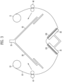
- FIG. 3 shows a schematic diagram of the movement of a first motor 41 and a second motor 42 according to an embodiment of the present invention.
- a first motor 41 may move a separator 12 in a direction for covering a first electrode 101 provided on a first table 21.
- a first motor 41 may be coupled to a separator 12 unwound from a first separator reel 10.
- a separator 12 may move.
- a first motor 41 may move in a direction for covering the first electrode 101 to move a separator 12.
- a first motor 41 may move a separator 12 by moving horizontally with a first table 21. In this process, one end of a first electrode 101 may be in contact with a separator 12, and the separator 12 may be folded due to a first electrode 101.
- a separator 12 may be positioned to cover an upper portion of a first electrode 101.
- a second motor 42 may move a separator 12 in a direction for covering a first electrode 101 provided on a second table 22.
- a second motor 42 may move a separator 12 unwound from a second separator reel 11 by fixing and coupling it.
- a second motor 42 may move a separator 12 by moving horizontally with a second table 22. In this process, one end of a second electrode 102 may be in contact with a separator 12, and the separator 12 may be folded due to a first electrode 101.
- a second motor 42 moves a sufficient distance, a separator 12 may be positioned to cover an upper portion of a first electrode 101.
- FIG. 4 shows a schematic diagram of a second electrode 102 being seated according to an embodiment of the present invention.
- an electrode header 30 may provide a second electrode 102 to a first table 21 and a second table 22.
- An electrode header 30 may further include a second electrode header 33 adsorbing and moving a second electrode 102.
- a second electrode 102 may be provided on a separator 12 positioned on a first table 21 and a second table 22. Specifically, after a separator 12 is stacked on a first table 21, a first electrode 101 may be stacked, and after a separator 12 is stacked again, a second electrode 102 may be stacked.
- a first electrode 101, a second electrode 102, and a separator 12 may be stacked in the same sequence as a stack is stacked on a first table 21.
- An electrode header 30 may further include a second electrode header 33 adsorbing and moving a second electrode 102.
- a second electrode header 33 is not limited to a method of adsorbing and moving as long as it can move without damaging the second electrode 102.
- a first electrode header 31 and a second electrode header 33 may be configured as separate devices.
- a first electrode header 31 and a second electrode header 33 move vertically in a direction perpendicular to the table to allow a first electrode 101 and a second electrode 102 to seat on a first table 21 and a second table 22.
- FIG. 5 shows a schematic diagram of the movement of a first motor 41 and a second motor 42 according to an embodiment of the present invention.
- a first motor 41 and a second motor 42 may move.
- a first motor 41 and a second motor 42 may move in a direction where a separator 12 covers a second electrode 102.
- a first motor 41 and a second motor 42 may move in a direction opposite to the direction in which the first motor 41 and the second motor 42 move a separator 12 to cover a first electrode 101.
- one end of a second electrode 102 may be in contact with a separator 12, and the separator 12 may be folded due to the second electrode 102.
- a separator 12 may be positioned to cover an upper portion of a second electrode 102.
- a first motor 41 may move a separator 12 by moving horizontally with a first table, or may move a separator 12 by undergoing a rotational movement.
- a second motor 42 may also undergo a rotational movement to move a separator 12.
- a separator 12 may be moved to cover a first electrode 101 or a second electrode 102, the movement of a first motor 41 and a second motor 42 is limited to a horizontal movement and a rotational movement.
- FIG. 6 shows a schematic diagram of a first half jelly roll 110 and a second half jelly roll 120 stacked according to an embodiment of the present invention.
- a separator 12 - a first electrode 101 - a separator 12 - a second electrode 102 - a separator 12 may be repeatedly positioned on a first table 21 to stack a first half jelly roll 110.
- a separator 12 - a first electrode 101 - a separator 12 - a second electrode 102 - a separator 12 may be repeatedly positioned on a second table 22 to form a second half jelly roll 120.
- the number of first electrodes 101 and second electrodes 102 is not limited.
- a first electrode 101 may be positioned at the top of a first half jelly roll 110 and a second half jelly roll 120.
- a first motor 41 may move horizontally with a first table 21 to cover a first electrode 101, and when a separator 12 covers a first electrode 101, a first half jelly roll 110 may be manufactured.
- a second motor 42 may move horizontally with a second table to cover a first electrode 101, and a separator 12 may cover a first electrode 101 and a second half jelly roll 120 may be manufactured.
- a first half jelly roll 110 and a second half jelly roll are connected through one separator 12.
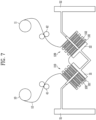
- FIG. 7 shows a schematic diagram of an assembly header 50 moving a first half jelly roll 110 and a second half jelly roll 120 according to an embodiment of the present invention.
- An assembly header 50 may form one half jelly roll by moving a first half jelly roll 110 and a second half jelly roll.
- An assembly header 50 may include a first assembly header 51 moving a first half jelly roll 110.
- a first assembly header 51 may move a first half jelly roll 110 by surrounding and fixing the first half jelly roll 110 from the outside.
- a first assembly header 51 may be moved without damaging the same by applying appropriate tension to a first half jelly roll 110
- the fixing and moving method is not limited.
- a first half jelly roll 110 may be fixed in the form of tongs as if surrounding the same, and a hexahedral container may be provided to accommodate a first half jelly roll 110 as if surrounding the same.
- an assembly header 50 may include a second assembly header 52 moving a second half jelly roll 120.
- the structure of a second assembly header 52 fixing a second half jelly roll 120 is not limited to the embodiment in the drawing.
- FIG. 8 shows a schematic diagram of an assembly header 50 assembling a first half jelly roll 110, a second half jelly roll 120, and a second electrode 102 and thereby stacking jelly rolls according to an embodiment of the present invention.
- An assembly header 50 may include a third assembly header 53 providing a second electrode 102.
- a third assembly header 53 may adsorb and move a second electrode 102, but the driving method is not limited thereto as long as a second electrode 102 may be moved without damaging the same.
- a third assembly header 53 may dispose a second electrode 102 between the first half jelly roll 110 and the second half jelly roll 120. Since a first half jelly roll 110 and a second half jelly roll 120 are connected through a separator 12, a second electrode 102 may be in contact with the connected separator 12 and may fold the separator 12.
- FIG. 9 shows a schematic diagram of a jelly roll surrounded by a separator 12 according to an embodiment of the present invention.
- a first half jelly roll 110, a second half jelly roll 120, and a second electrode 102 may be coupled into a preliminary stack 130 by a stacking header 60.
- a stacking header 60 may be replaced with an assembly header 50. Therefore, a first assembly header 51, a second assembly header 52, or a third assembly header 53 may fix a preliminary stack 130 in which a first half jelly roll 110, a second half jelly roll 120, and a second electrode 102 are combined.
- a stacking header 60 may be configured as a separate device from an assembly header 50.
- a stacking header 60 may rotate a preliminary stack 130 to surround the preliminary stack 130 with a separator 12.
- a separator 12 surrounding a preliminary stack 130 may be formed by being connected to both a first separator reel 10 and a second separator reel 11.
- a separator 12 connected to a second separator reel 11 may be cut at one end of a preliminary stack 130. Since the other end of the preliminary stack 130 is connected to a first separator reel 10, an electrode header 30 may rotate the preliminary stack 130 as if surrounding a separator 10 unwound from the first separator reel 10 from the outside of the preliminary stack 130.
- a preliminary stack 130 may be surrounded by a separator 12 and the separator 12 may be bonded to manufacture an electrode assembly 100.
- FIG. 10 shows a flowchart of a sequence of manufacturing an electrode assembly according to an embodiment of the present invention.
- an electrode assembly may be manufactured through a separator unwinding step S 10, a separator disposing step S20, a first electrode disposing step S30, a separator moving step S40, a second electrode disposing step S50, a separator moving step S60, a half jelly roll stacking step S70, and a preliminary stack assembling step S80.
- a separator may be unwound from a first separator reel in a direction to a first table, and a separator may be unwound from a second separator reel in a direction to a second table.
- the present disclosure may unwind a separator from a first separator reel in a direction to a first table and may unwind a separator from a second separator reel in a direction to a second table.
- a separator 12 may be unwound from each of a first separator reel 10 and a second separator reel 11.
- a separator 12 unwound from a first separator reel 10 and a second separator reel 11 may be formed as one continuous separator 12. Both ends of a separator 12 may each be wound around a first separator reel 10 and a second separator reel 11.
- Preferably, half of a separator may be wound around a first separator reel 10, and the other half may be wound around a second separator reel 12.
- a first separator may be disposed on a first table, and a second separator may be disposed on a second table.
- the present disclosure may dispose a first separator on the first table and may dispose a second separator on the second table.
- a separator 12 may each be disposed on a first table 21 and a second table 22.
- a first table 21 and a second table 22 are places where a first half jelly roll 110 and a second half jelly roll 120 including a separator are manufactured, so it may be desirable that they have a flat cross-section.
- a first electrode header may dispose a first electrode on a first table and a second table.
- An electrode header 30 may dispose a first electrode 101 on a separator disposed on a first table 21 and a second table 22.
- the present disclosure may dispose a first electrode on the first table and the second table.
- a first electrode 101 may be disposed on a first table 21 and a second table 22 at the same time. According to an embodiment, a first electrode 101 may be disposed on a first table 21 first, and then the first electrode 101 may be disposed on a second table 22. It may be performed in the opposite sequence. As long as a first electrode 101 may be disposed on a first table 21 and a second table 22, the sequence is not limited.
- a first motor may move a separator on a first table and a second motor may move a separator on a second table.
- the present disclosure may move a separator on the first table by a first motor and may move a separator on the second table by a second motor.
- a first motor 41 may move in conjunction with one region of a separator 12 positioned between a first table 21 and a first separator reel 10, thereby moving the separator 12.
- a separator 12 may cover a first electrode 101.
- a second motor 42 may move the separator 12 to cover the first electrode 101.
- a first electrode header may dispose a second electrode on a first table and a second table.
- the present disclosure may dispose a second electrode on the first table and the second table.
- an electrode header 30 allows a second electrode 102 to seat on each of a first table 21 and a second table 22.
- An electrode header 30 may include a second electrode header 33 moving a second electrode.
- a separator moving step S60 may be carried out.
- a first motor 41 moves in conjunction with one region of the separator 12 positioned between a first table 21 and a first separator reel 10 to move the separator 12, thereby covering a second electrode 102.
- a second motor 42 moves in conjunction with one region of the separator 12 positioned between a second table 22 and a second separator reel to move the separator 12, thereby covering a second electrode 102.
- a process of disposing a first electrode 101 and disposing a second electrode 102 may be repeated.
- the number of times of repeating the process is not limited, and the process may be repeated as many times as preset by a user to carry out stacking.
- a first half jelly roll 110 may be manufactured on a first table 21 and a second half jelly roll 120 may be manufactured on a second table.
- an assembly header may provide a second electrode between a first half jelly roll stacked on a first table and a second half jelly roll stacked on a second table.
- the present disclosure may prove the second electrode between a first half jelly roll stacked on the first table and a second half jelly roll stacked on the second table.
- the manufactured first half jelly roll 110 and second half jelly roll 120 are coupled and moved by an assembly header 50, and the assembly header 50 may dispose a second electrode 102 between a first half jelly roll 110 and a second half jelly roll 120.
- An assembly header 50 may include a first assembly header 51 moving a first half jelly roll 110, may include a second assembly header 52 moving a second half jelly roll 120, and may include a third assembly header 53 disposing a second electrode.
- a stacking header may surround the circumference of a stacked half jelly roll with a separator.
- the present disclosure may surround the circumference of the stacked half jelly roll with a separator.
- a process of surrounding a preliminary stack 130 with a separator may be performed.
- a separator 12 included in a preliminary stack 130 may be connected to a first separator reel 10 and a second separator reel 11. According to an embodiment, a separator 12 connected to a second separator reel 11 may be cut.
- a stacking header 60 may fix and rotate a preliminary stack 130 to surround a separator connected to a first separator reel 10 along the outside of the preliminary stack 130 and bond a separator 12 to manufacture an electrode assembly 100.
- a stacking header 60 may be replaced with an assembly header 50. Therefore, a first assembly header 51, a second assembly header 52, or a third assembly header 53 may fix a preliminary stack 130 formed by combining a first half jelly roll 110, a second half jelly roll 120, and a second electrode 102.
- a stacking header 60 may be configured as a separate device from an assembly header 50.
- an electrode assembly manufacturing apparatus and a manufacturing method of the same can increase the productivity of an electrode assembly and provide an electrode assembly with an improved defect rate.
Landscapes
- Engineering & Computer Science (AREA)
- Chemical & Material Sciences (AREA)
- Manufacturing & Machinery (AREA)
- Chemical Kinetics & Catalysis (AREA)
- Electrochemistry (AREA)
- General Chemical & Material Sciences (AREA)
- Mechanical Engineering (AREA)
- Materials Engineering (AREA)
- Secondary Cells (AREA)
Abstract
An electrode assembly manufacturing apparatus and method according to one embodiment of the present invention may comprise: a first table on which a first half jelly roll is stacked; a second table on which a second half jelly roll is stacked; a separator disposed on the first table and the second table; a first separator reel unwinding the separator in a direction to the first table; a second separator reel unwinding the separator in a direction to the second table; an electrode header providing a first electrode and a second electrode to the first table and the second table; a first motor moving the separator in a direction for covering the first electrode and the second electrode provided on the first table; a second motor moving the separator in a direction for covering the first electrode and the second electrode provided on the second table; and an assembly header providing the second electrode between the first half jelly roll and the second half jelly roll.
Description
- The present invention relates to an electrode assembly manufacturing apparatus and a manufacturing method of the same.
- As the electronics, communications, and space industries develop, demand for lithium secondary batteries as an energy power source is drastically increasing. In particular, as the importance of global eco-friendly policies is emphasized, the electric vehicle market is growing swiftly, and research and development on lithium secondary batteries are being actively conducted worldwide.
- An electrode assembly mounted in secondary batteries is a power generation element composed of a structure in which a cathode, an anode, and a separator interposed therebetween are stacked. Electrode assemblies are classified into a jelly roll type formed by interposing a separator between a cathode and an anode in the form of a long sheet coated with an active material and winding the same; and a stack type formed by stacking multiple cathodes and anodes of a predetermined size with a separator interposed therebetween.
- A stack type electrode assembly had a problem that stacking cathodes, anodes, and separators take much time. To solve this problem, an attempt was made to increase efficiency by moving a table on which electrode assemblies was stacked, but as the stack continued to move, there was a problem that the electrodes deviated from their right positions and stability deteriorated.
- A problem that the present disclosure aims to solve is to provide an apparatus and a method for manufacturing an electrode assembly that can prevent electrodes from deviating from their right positions and increase productivity when stacking electrodes and separators in a stacked type.
- The problems of the present invention are not limited to the problem mentioned above, and other problems that are not mentioned may be clearly understood by those skilled in the art from the description below.
- The battery cell of the present disclosure can be widely applied in the field of green technology, such as electric vehicles, battery charging stations, solar power generation, and wind power generation using batteries. In addition, the battery cell of the present disclosure can be used in eco-friendly electric vehicles, hybrid vehicles, etc. to prevent climate change by suppressing air pollution and greenhouse gas emissions.
- An electrode assembly manufacturing apparatus according to the present invention may include: a first table on which a first half jelly roll is stacked; a second table on which a second half jelly roll is stacked; a separator disposed on the first table and the second table; a first separator reel unwinding the separator in a direction to the first table; a second separator reel unwinding the separator in a direction to the second table; an electrode header providing a first electrode and a second electrode to the first table and the second table; a first motor moving the separator in a direction for covering the first electrode and the second electrode provided on the first table; a second motor moving the separator in a direction for covering the first electrode and the second electrode provided on the second table; and an assembly header providing the second electrode between the first half jelly roll and the second half jelly roll.
- In one embodiment of the present invention, a first table and a second table may be physically connected.
- In one embodiment of the present invention, a first table may include a first leg, and a second table may include a second leg, so that the first leg and the second leg may be formed to be perpendicular.
- In one embodiment of the present invention, a first motor may move a separator by repeatedly moving horizontally with a first table.
- In one embodiment of the present invention, a second motor may move a separator by repeatedly moving horizontally with a second table.
- In one embodiment of the present invention, an electrode header may include a first electrode header disposing a first electrode on a first table and a second table.
- In one embodiment of the present invention, an electrode header may include a second electrode header disposing a second electrode on a first table and a second table.
- In one embodiment of the present invention, an assembly header may include a first assembly header surrounding and moving a first half jelly roll.
- In one embodiment of the present invention, an assembly header may include a second assembly header surrounding and moving a second half jelly roll.
- In one embodiment of the present invention, an assembly header may include a third assembly header providing a second electrode.
- In one embodiment of the present invention, the electrode assembly manufacturing apparatus may include a stacking header surrounding a first half jelly roll, a second half jelly roll, and a second electrode with a separator.
- An electrode assembly manufacturing method according to the present invention may include: a step in which a separator is unwound from a first separator reel in a direction to a first table and a separator is unwound from a second separator reel in a direction to a second table; a step in which a first separator is disposed on the first table and a second separator is disposed on the second table; a step in which a first electrode header disposes a first electrode on the first table and the second table; a step in which a first motor moves a separator on the first table and a second motor moves a separator on the second table; a step in which a first electrode header disposes a second electrode on the first table and the second table; a step in which an assembly header provides the second electrode between a first half jelly roll stacked on the first table and a second half jelly roll stacked on the second table; and a step in which a stacking header surrounds the circumference of the stacked half jelly roll with a separator.
- The present invention can increase the productivity of electrode assembly by improving the speed of stacking a cathode, an anode, and a separator.
- The present invention can prevent the problem that an electrode deviates from the right position to reduce the defect rate because a table on which stacks are manufactured is fixed.
-
-
FIG. 1 shows a diagram of an electrode assembly manufactured according to an embodiment of the present invention. -
FIG. 2 shows a schematic diagram of a first electrode being seated according to an embodiment of the present invention. -
FIG. 3 shows a schematic diagram of the movement of a first motor and a second motor according to an embodiment of the present invention. -
FIG. 4 shows a schematic diagram of a second electrode being seated according to an embodiment of the present invention. -
FIG. 5 shows a schematic diagram of the movement of a first motor and a second motor according to an embodiment of the present invention. -
FIG. 6 shows a schematic diagram of a first half jelly roll and a second half jelly roll stacked according to an embodiment of the present invention. -
FIG. 7 shows a schematic diagram of an assembly header moving a first half jelly roll and a second half jelly roll according to an embodiment of the present invention. -
FIG. 8 shows a schematic diagram of an assembly header assembling a first half jelly roll, a second half jelly roll, and a second electrode and thereby stacking jelly rolls according to an embodiment of the present invention. -
FIG. 9 shows a schematic diagram of a jelly roll surrounded by a separator according to an embodiment of the present invention. -
FIG. 10 shows a flowchart of a sequence of manufacturing an electrode assembly according to an embodiment of the present invention. - Terms or words used in the present specification and claims should not be construed as limited to their common or dictionary meanings, and should be construed as meanings and concepts consistent with the technical idea of the present invention based on the principle that an inventor may appropriately define the concept of terms in order to explain their invention in the best way. Therefore, the embodiments described in the present specification and the configurations illustrated in the drawings are merely one of the most preferred embodiments of the present invention and do not entirely represent the technical idea of the present invention. Therefore, it should be understood that at the time of filing the present application, various equivalents and modification examples that can replace them may exist.
- Since the embodiments of the present invention are provided to more completely explain the present invention to those skilled in the art, the shapes, sizes or the like of the components in the drawings may be exaggerated, omitted, or schematically illustrated for clearer description. Therefore, the size or proportion of each component does not entirely reflect the actual size or proportion.
- Hereinafter, with reference to the attached drawings, an electrode assembly manufacturing apparatus and a manufacturing method according to an embodiment of the present invention will be described in detail.
-
FIG. 1 shows a diagram of anelectrode assembly 100 manufactured according to an embodiment of the present invention. Anelectrode assembly 100 includes a cathode, an anode, and a separator disposed between the cathode and the anode. According to an embodiment, aseparator 12 may be interposed between afirst electrode 101 and asecond electrode 102 to manufacture an electrode assembly. Afirst electrode 101 and asecond electrode 102 may be a cathode or an anode. Afirst electrode 101 and Asecond electrode 102 refer to different electrodes. For example, when afirst electrode 101 is a cathode, asecond electrode 102 is an anode; and when afirst electrode 101 is an anode, asecond electrode 102 refers to a cathode. - A cathode and an anode may include a current collector and an active material layer disposed on the current collector. For example, a cathode may include a cathode current collector and a cathode active material layer, and an anode may include an anode current collector and an anode active material layer.
- A current collector may include a known conductive material to an extent that it does not cause a chemical reaction within a lithium secondary battery. For example, a current collector may include any one of stainless steel, nickel (Ni), aluminum (Al), titanium (Ti), copper (Cu), and alloys thereof, and may be provided in various forms such as film, sheet, and foil.
- An active material layer includes an active material. For example, a cathode active material layer may include a cathode active material, and an anode active material layer may include an anode active material.
- A cathode active material may be a material which lithium ions may be inserted to and extracted from. A cathode active material may be a lithium metal oxide. For example, a cathode active material may be one of a lithium manganese oxide, a lithium nickel oxide, a lithium cobalt oxide, a lithium nickel manganese oxide, a lithium nickel cobalt manganese oxide, a lithium nickel cobalt aluminum oxide, a lithium iron phosphate-based compound, a lithium manganese phosphate-based compound, a lithium cobalt phosphate-based compound and a lithium vanadium phosphate-based compound.
- An anode active material may be a material which lithium ions may be inserted to and extracted from. For example, an anode active material may be any one of carbon-based materials such as crystalline carbon, amorphous carbon, carbon composite, and carbon fiber, a lithium alloy, silicon (Si), and tin (Sn). According to an embodiment, an anode active material may be natural graphite or artificial graphite, but is not limited to a specific example.
- A cathode and an anode may each further include a binder and a conductive material. A binder may improve mechanical stability by mediating a bond between a current collector and an active material layer. For example, a binder may be an organic binder or an aqueous binder. For example, an organic binder may be one of vinylidene fluoride-hexafluoropropylene copolymer (PVDF-co-HFP), polyvinylidene fluoride (PVDF), polyacrylonitrile, and polymethylmethacrylate, and an aqueous binder may be styrene-butadiene rubber (SBR), but they are not limited thereto.
- A conductive material may improve electrical conductivity of a secondary battery. A conductive material may include a metal-based material. According to an embodiment, a conductive material may include a conventional carbon-based conductive material. For example, a conductive material may include any one of graphite, carbon black, graphene, and carbon nanotubes, and preferably, a conductive material may include carbon nanotubes.
- A separator is disposed between a cathode and an anode. A separator may be configured to prevent an electrical short between a cathode and an anode and to generate a flow of ions. For example, a separator may include a porous polymer film or a porous nonwoven fabric. A porous polymer film may be configured as a single layer or a multi-layer including a polyolefin polymer such as an ethylene polymer, a propylene polymer, an ethylene/butene copolymer, an ethylene/hexene copolymer, and an ethylene/methacrylate copolymer. A porous nonwoven fabric may include glass fibers of a high melting point and polyethylene terephthalate fibers. However, it is not limited thereto, and according to an embodiment, a separator may be a ceramic coated separator including ceramic.
-
FIG. 2 shows a schematic diagram of a first electrode being seated according to an embodiment of the present invention. According to an embodiment, an electrode assembly manufacturing apparatus 200 includes: a first table 21, a second table 22, aseparator 12, afirst separator reel 10, asecond separator reel 11, an electrode header, afirst motor 41, asecond motor 42, and anassembly header 50. Ahalf jelly roll 110 may be stacked on a first table 21. A secondhalf jelly roll 120 may be stacked on a second table 22. That is, a firsthalf jelly roll 110 may be stacked on a first table 21, and a secondhalf jelly roll 120 may be stacked on a second table 22. - A first
half jelly roll 110 may refer to a stack produced by stacking afirst electrode 101, asecond electrode 102, and aseparator 12 on a first table 21; and a secondhalf jelly roll 120 may refer to a stack produced by stacking afirst electrode 101, asecond electrode 102, and aseparator 12 on a second table 22. - As will be described later, a first
half jelly roll 110 and a secondhalf jelly roll 120 may be combined to configure oneelectrode assembly 100. According to an embodiment, when an electrode assembly is manufactured by configuring with two stacks, instead of configuring with one stack, and combining the stacks, productivity can be increased. - A first table 21 and a second table 22 are places where a first
half jelly roll 110 and a secondhalf jelly roll 110 are manufactured, as afirst electrode 101, asecond electrode 102, and aseparator 12 are seated and stacked on the upper surfaces thereof. A first table 21 and a second table 22 may preferably include a flat cross-section so that a firsthalf jelly roll 110 and a secondhalf jelly roll 120 may be stacked, respectively. Aseparator 12 may be unwound from afirst separator reel 10 and asecond separator reel 11 and disposed on a first table 21 and a second table 22. Aseparator 12 unwound from afirst separator reel 10 and asecond separator reel 11 may be formed as onecontinuous separator 12. - Both ends of one
separator 12 may be wound around afirst separator reel 10 and asecond separator reel 11, respectively. Preferably, half of a separator may be wound around afirst separator reel 10, and the other half may be wound around asecond separator reel 11. - A
separator 12 disposed on a first table 21 may be unwound from afirst separator reel 10. Aseparator 12 disposed on a second table 22 may be unwound from asecond separator reel 11. Through this, aseparator 12 may be unwound from each of afirst separator reel 10 and asecond separator reel 11 so that stacking can be quickly performed. - A first table 21 may include a
first leg 23, and a second table 22 may include asecond leg 24. Afirst leg 23 may be connected to a first table 21 and may change the position of a first table 21. For example, afirst leg 23 may move a first table 21 so that the first table 21 may be horizontal or inclined with respect to the ground. - A
second leg 24 is connected to a second table 22. Asecond leg 24 may be connected to a second table 22 and may change the position of a second table. For example, asecond leg 24 may move a second table 22 so that the second table 22 may be horizontal or inclined with respect to the ground. - A first table 21 and a second table 22 may be physically connected. According to an embodiment, a first table 21 may be connected to a
first leg 23 and a second table 22 may be connected to asecond leg 24, and as afirst leg 23 and asecond leg 24 are connected, a first table 21 and a second table 22 may be connected. Afirst leg 23 and asecond leg 24 may be connected around an axis. - According to an embodiment, a
first leg 23 and asecond leg 24 may be formed to be perpendicular. As afirst leg 23 and asecond leg 24 are formed to be perpendicular, afirst leg 23 and asecond leg 24 may be formed at an angle of 45 degrees with the ground. - A first table 21 is perpendicularly coupled to a
first leg 23, and a second table 22 is perpendicularly coupled to asecond leg 24 so that a first table 21 and a second table 22 may be formed at an angle of 45 degrees with the ground. - Of course, it is not limited to this, and a
first leg 23 and asecond leg 24 may form an arbitrary angle with the ground. - By forming a certain angle with the ground, an electrode header described later can easily stack a
first electrode 101 and asecond electrode 102. - A
separator 12 may be fixed between a first table 21 and a second table 22 through a gripper. A gripper may be positioned between a first table 21 and a second table 22 to fix the position of aseparator 12. When aseparator 12 is disposed on a first table 21 and a second table 22, anelectrode header 30 may provide afirst electrode 101 and asecond electrode 102. - An
electrode header 30 may move afirst electrode 101 and asecond electrode 102 by adsorbing one surface of thefirst electrode 101 and thesecond electrode 102, but it is not limited as long as it is a means that can move the position without damaging the electrodes. Anelectrode header 30 may include afirst electrode header 31 moving afirst electrode 101. - A
first electrode 101 may be disposed on aseparator 12 disposed on a first table 21. Specifically, when aseparator 12 is disposed flat on one region of a first table 21, afirst electrode 101 may be stacked above theseparator 12. Afirst electrode 101 may be disposed on aseparator 12 disposed on a second table 22. - A
first electrode 101 may be dispose on a first table 21 and a second table 22 at the same time, but after disposing afirst electrode 101 on a first table 21, thefirst electrode 101 may be disposed on a second table 22. The sequence is not limited as long as afirst electrode 101 is each disposed on aseparator 12 disposed on a first table 21 and a second table 22. - Through this, half jelly rolls may be stacked on a first table 21 and a second table 22, respectively, and productivity and efficiency can be improved. A
first electrode header 31 may be provided with a plurality of firstelectrode header arms 32 that can simultaneously stack afirst electrode 101 on a first table 21 and a second table 22. -
FIG. 3 shows a schematic diagram of the movement of afirst motor 41 and asecond motor 42 according to an embodiment of the present invention. Afirst motor 41 may move aseparator 12 in a direction for covering afirst electrode 101 provided on a first table 21. Afirst motor 41 may be coupled to aseparator 12 unwound from afirst separator reel 10. - As a
first motor 41 moves, aseparator 12 may move. When afirst electrode 101 is dispose on a first table 21, afirst motor 41 may move in a direction for covering thefirst electrode 101 to move aseparator 12. Afirst motor 41 may move aseparator 12 by moving horizontally with a first table 21. In this process, one end of afirst electrode 101 may be in contact with aseparator 12, and theseparator 12 may be folded due to afirst electrode 101. When afirst motor 41 moves a sufficient distance, aseparator 12 may be positioned to cover an upper portion of afirst electrode 101. - A
second motor 42 may move aseparator 12 in a direction for covering afirst electrode 101 provided on a second table 22. Asecond motor 42 may move aseparator 12 unwound from asecond separator reel 11 by fixing and coupling it. When afirst electrode 101 is disposed on a second table 22, asecond motor 42 may move aseparator 12 by moving horizontally with a second table 22. In this process, one end of asecond electrode 102 may be in contact with aseparator 12, and theseparator 12 may be folded due to afirst electrode 101. When asecond motor 42 moves a sufficient distance, aseparator 12 may be positioned to cover an upper portion of afirst electrode 101. -
FIG. 4 shows a schematic diagram of asecond electrode 102 being seated according to an embodiment of the present invention. As described above, anelectrode header 30 may provide asecond electrode 102 to a first table 21 and a second table 22. Anelectrode header 30 may further include asecond electrode header 33 adsorbing and moving asecond electrode 102. Asecond electrode 102 may be provided on aseparator 12 positioned on a first table 21 and a second table 22. Specifically, after aseparator 12 is stacked on a first table 21, afirst electrode 101 may be stacked, and after aseparator 12 is stacked again, asecond electrode 102 may be stacked. On a second table 22, afirst electrode 101, asecond electrode 102, and aseparator 12 may be stacked in the same sequence as a stack is stacked on a first table 21. - An
electrode header 30 may further include asecond electrode header 33 adsorbing and moving asecond electrode 102. As described above, the configuration of asecond electrode header 33 is not limited to a method of adsorbing and moving as long as it can move without damaging thesecond electrode 102. Afirst electrode header 31 and asecond electrode header 33 may be configured as separate devices. - A
first electrode header 31 and asecond electrode header 33 move vertically in a direction perpendicular to the table to allow afirst electrode 101 and asecond electrode 102 to seat on a first table 21 and a second table 22. -
FIG. 5 shows a schematic diagram of the movement of afirst motor 41 and asecond motor 42 according to an embodiment of the present invention. According to an embodiment, when asecond electrode 102 is stacked above aseparator 12, afirst motor 41 and asecond motor 42 may move. Afirst motor 41 and asecond motor 42 may move in a direction where aseparator 12 covers asecond electrode 102. - As described above, a
first motor 41 and asecond motor 42 may move in a direction opposite to the direction in which thefirst motor 41 and thesecond motor 42 move aseparator 12 to cover afirst electrode 101. In this process, one end of asecond electrode 102 may be in contact with aseparator 12, and theseparator 12 may be folded due to thesecond electrode 102. When afirst motor 41 and asecond motor 42 move a sufficient distance, aseparator 12 may be positioned to cover an upper portion of asecond electrode 102. - As described above, a
first motor 41 may move aseparator 12 by moving horizontally with a first table, or may move aseparator 12 by undergoing a rotational movement. In addition, asecond motor 42 may also undergo a rotational movement to move aseparator 12. When aseparator 12 may be moved to cover afirst electrode 101 or asecond electrode 102, the movement of afirst motor 41 and asecond motor 42 is limited to a horizontal movement and a rotational movement. -
FIG. 6 shows a schematic diagram of a firsthalf jelly roll 110 and a secondhalf jelly roll 120 stacked according to an embodiment of the present invention. A separator 12 - a first electrode 101 - a separator 12 - a second electrode 102 - aseparator 12 may be repeatedly positioned on a first table 21 to stack a firsthalf jelly roll 110. A separator 12 - a first electrode 101 - a separator 12 - a second electrode 102 - aseparator 12 may be repeatedly positioned on a second table 22 to form a secondhalf jelly roll 120. The number offirst electrodes 101 andsecond electrodes 102 is not limited. According to an embodiment, afirst electrode 101 may be positioned at the top of a firsthalf jelly roll 110 and a secondhalf jelly roll 120. Afirst motor 41 may move horizontally with a first table 21 to cover afirst electrode 101, and when aseparator 12 covers afirst electrode 101, a firsthalf jelly roll 110 may be manufactured. Asecond motor 42 may move horizontally with a second table to cover afirst electrode 101, and aseparator 12 may cover afirst electrode 101 and a secondhalf jelly roll 120 may be manufactured. A firsthalf jelly roll 110 and a second half jelly roll are connected through oneseparator 12. -
FIG. 7 shows a schematic diagram of anassembly header 50 moving a firsthalf jelly roll 110 and a secondhalf jelly roll 120 according to an embodiment of the present invention. Anassembly header 50 may form one half jelly roll by moving a firsthalf jelly roll 110 and a second half jelly roll. Anassembly header 50 may include afirst assembly header 51 moving a firsthalf jelly roll 110. Afirst assembly header 51 may move a firsthalf jelly roll 110 by surrounding and fixing the firsthalf jelly roll 110 from the outside. - As long as a
first assembly header 51 may be moved without damaging the same by applying appropriate tension to a firsthalf jelly roll 110, the fixing and moving method is not limited. For example, a firsthalf jelly roll 110 may be fixed in the form of tongs as if surrounding the same, and a hexahedral container may be provided to accommodate a firsthalf jelly roll 110 as if surrounding the same. In this case, since a firsthalf jelly roll 110 does not flow down, a stable structure may be maintained. In addition, anassembly header 50 may include asecond assembly header 52 moving a secondhalf jelly roll 120. As long as asecond assembly header 52 may move a secondhalf jelly roll 120 without damaging the same, the structure of asecond assembly header 52 fixing a secondhalf jelly roll 120 is not limited to the embodiment in the drawing. -
FIG. 8 shows a schematic diagram of anassembly header 50 assembling a firsthalf jelly roll 110, a secondhalf jelly roll 120, and asecond electrode 102 and thereby stacking jelly rolls according to an embodiment of the present invention. Anassembly header 50 may include athird assembly header 53 providing asecond electrode 102. Athird assembly header 53 may adsorb and move asecond electrode 102, but the driving method is not limited thereto as long as asecond electrode 102 may be moved without damaging the same. According to an embodiment, when afirst assembly header 51 fixes a firsthalf jelly roll 110 and positions the same upward and asecond assembly header 52 fixes a secondhalf jelly roll 120 and positions the same downward, athird assembly header 53 may dispose asecond electrode 102 between the firsthalf jelly roll 110 and the secondhalf jelly roll 120. Since a firsthalf jelly roll 110 and a secondhalf jelly roll 120 are connected through aseparator 12, asecond electrode 102 may be in contact with the connectedseparator 12 and may fold theseparator 12. -
FIG. 9 shows a schematic diagram of a jelly roll surrounded by aseparator 12 according to an embodiment of the present invention. A firsthalf jelly roll 110, a secondhalf jelly roll 120, and asecond electrode 102 may be coupled into apreliminary stack 130 by a stackingheader 60. A stackingheader 60 may be replaced with anassembly header 50. Therefore, afirst assembly header 51, asecond assembly header 52, or athird assembly header 53 may fix apreliminary stack 130 in which a firsthalf jelly roll 110, a secondhalf jelly roll 120, and asecond electrode 102 are combined. According to an embodiment, a stackingheader 60 may be configured as a separate device from anassembly header 50. - A stacking
header 60 may rotate apreliminary stack 130 to surround thepreliminary stack 130 with aseparator 12. Aseparator 12 surrounding apreliminary stack 130 may be formed by being connected to both afirst separator reel 10 and asecond separator reel 11. - According to an embodiment, a
separator 12 connected to asecond separator reel 11 may be cut at one end of apreliminary stack 130. Since the other end of thepreliminary stack 130 is connected to afirst separator reel 10, anelectrode header 30 may rotate thepreliminary stack 130 as if surrounding aseparator 10 unwound from thefirst separator reel 10 from the outside of thepreliminary stack 130. Apreliminary stack 130 may be surrounded by aseparator 12 and theseparator 12 may be bonded to manufacture anelectrode assembly 100. -
FIG. 10 shows a flowchart of a sequence of manufacturing an electrode assembly according to an embodiment of the present invention. According to an embodiment, an electrode assembly may be manufactured through a separatorunwinding step S 10, a separator disposing step S20, a first electrode disposing step S30, a separator moving step S40, a second electrode disposing step S50, a separator moving step S60, a half jelly roll stacking step S70, and a preliminary stack assembling step S80. - In a separator unwinding step S10, a separator may be unwound from a first separator reel in a direction to a first table, and a separator may be unwound from a second separator reel in a direction to a second table. In a separator unwinding step S10, the present disclosure may unwind a separator from a first separator reel in a direction to a first table and may unwind a separator from a second separator reel in a direction to a second table.
- In other words, a
separator 12 may be unwound from each of afirst separator reel 10 and asecond separator reel 11. Aseparator 12 unwound from afirst separator reel 10 and asecond separator reel 11 may be formed as onecontinuous separator 12. Both ends of aseparator 12 may each be wound around afirst separator reel 10 and asecond separator reel 11. Preferably, half of a separator may be wound around afirst separator reel 10, and the other half may be wound around asecond separator reel 12. - In a separator disposing step S20, a first separator may be disposed on a first table, and a second separator may be disposed on a second table. In a separator disposing step, the present disclosure may dispose a first separator on the first table and may dispose a second separator on the second table.
- In other words, a
separator 12 may each be disposed on a first table 21 and a second table 22. A first table 21 and a second table 22 are places where a firsthalf jelly roll 110 and a secondhalf jelly roll 120 including a separator are manufactured, so it may be desirable that they have a flat cross-section. - In a first electrode disposing step S30, a first electrode header may dispose a first electrode on a first table and a second table. An
electrode header 30 may dispose afirst electrode 101 on a separator disposed on a first table 21 and a second table 22. In a first electrode disposing step S30, the present disclosure may dispose a first electrode on the first table and the second table. - A
first electrode 101 may be disposed on a first table 21 and a second table 22 at the same time. According to an embodiment, afirst electrode 101 may be disposed on a first table 21 first, and then thefirst electrode 101 may be disposed on a second table 22. It may be performed in the opposite sequence. As long as afirst electrode 101 may be disposed on a first table 21 and a second table 22, the sequence is not limited. - In a separator moving step S40, a first motor may move a separator on a first table and a second motor may move a separator on a second table. In a separator moving step S40, the present disclosure may move a separator on the first table by a first motor and may move a separator on the second table by a second motor. When a
first electrode 101 is seated above aseparator 12, afirst motor 41 may move in conjunction with one region of aseparator 12 positioned between a first table 21 and afirst separator reel 10, thereby moving theseparator 12. Through this, aseparator 12 may cover afirst electrode 101. By moving in conjunction with one region of aseparator 12 positioned between aseparator 12 seated on a second table and asecond separator reel 11, asecond motor 42 may move theseparator 12 to cover thefirst electrode 101. - In a second electrode disposing step S50, a first electrode header may dispose a second electrode on a first table and a second table. In a second electrode disposing step S50, the present disclosure may dispose a second electrode on the first table and the second table. When a
separator 12 covers afirst electrode 101, anelectrode header 30 allows asecond electrode 102 to seat on each of a first table 21 and a second table 22. Anelectrode header 30 may include asecond electrode header 33 moving a second electrode. - After a second electrode disposing step S50, a separator moving step S60 may be carried out. When a
second electrode 102 is seated above aseparator 12, afirst motor 41 moves in conjunction with one region of theseparator 12 positioned between a first table 21 and afirst separator reel 10 to move theseparator 12, thereby covering asecond electrode 102. In addition, asecond motor 42 moves in conjunction with one region of theseparator 12 positioned between a second table 22 and a second separator reel to move theseparator 12, thereby covering asecond electrode 102. - Thereafter, a process of disposing a
first electrode 101 and disposing asecond electrode 102 may be repeated. The number of times of repeating the process is not limited, and the process may be repeated as many times as preset by a user to carry out stacking. - Through repetition, a first
half jelly roll 110 may be manufactured on a first table 21 and a secondhalf jelly roll 120 may be manufactured on a second table. - In a half jelly roll stacking step S70, an assembly header may provide a second electrode between a first half jelly roll stacked on a first table and a second half jelly roll stacked on a second table. In a half jelly roll stacking step S70, the present disclosure may prove the second electrode between a first half jelly roll stacked on the first table and a second half jelly roll stacked on the second table.
- The manufactured first
half jelly roll 110 and secondhalf jelly roll 120 are coupled and moved by anassembly header 50, and theassembly header 50 may dispose asecond electrode 102 between a firsthalf jelly roll 110 and a secondhalf jelly roll 120. - An
assembly header 50 may include afirst assembly header 51 moving a firsthalf jelly roll 110, may include asecond assembly header 52 moving a secondhalf jelly roll 120, and may include athird assembly header 53 disposing a second electrode. - In a preliminary stack assembling step S80, a stacking header may surround the circumference of a stacked half jelly roll with a separator. In a preliminary stack assembling step S80, the present disclosure may surround the circumference of the stacked half jelly roll with a separator. A process of surrounding a
preliminary stack 130 with a separator may be performed. Aseparator 12 included in apreliminary stack 130 may be connected to afirst separator reel 10 and asecond separator reel 11. According to an embodiment, aseparator 12 connected to asecond separator reel 11 may be cut. - Thereafter, a stacking
header 60 may fix and rotate apreliminary stack 130 to surround a separator connected to afirst separator reel 10 along the outside of thepreliminary stack 130 and bond aseparator 12 to manufacture anelectrode assembly 100. A stackingheader 60 may be replaced with anassembly header 50. Therefore, afirst assembly header 51, asecond assembly header 52, or athird assembly header 53 may fix apreliminary stack 130 formed by combining a firsthalf jelly roll 110, a secondhalf jelly roll 120, and asecond electrode 102. According to an embodiment, a stackingheader 60 may be configured as a separate device from anassembly header 50. - As described above, an electrode assembly manufacturing apparatus and a manufacturing method of the same according to an embodiment of the present invention can increase the productivity of an electrode assembly and provide an electrode assembly with an improved defect rate.
- Although the present invention has been described above with limited embodiments and drawings, the present invention is not limited thereto, and various corrections and modifications are possible within the equivalent scope of the technical idea and the claims by those skilled in the art in the technical field to which the present invention pertains.
Claims (14)
- An electrode assembly manufacturing apparatus comprising:a first table on which a first half jelly roll is stacked;a second table on which a second half jelly roll is stacked;a separator disposed on the first table and the second table;a first separator reel unwinding the separator in a direction to the first table;a second separator reel unwinding the separator in a direction to the second table;an electrode header providing a first electrode and a second electrode to the first table and the second table;a first motor moving the separator in a direction for covering the first electrode and the second electrode provided on the first table;a second motor moving the separator in a direction for covering the first electrode and the second electrode provided on the second table; andan assembly header providing the second electrode between the first half jelly roll and the second half jelly roll.
- The electrode assembly manufacturing apparatus according to claim 1, wherein the first table and the second table are connected with each other.
- The electrode assembly manufacturing apparatus according to claims 1 or 2, wherein the first table includes a first leg, and the second table includes a second leg, and the first leg and the second leg are formed to be perpendicular.
- The electrode assembly manufacturing apparatus according to any one of the preceding claims, wherein the first motor moves the separator by moving horizontally with the first table.
- The electrode assembly manufacturing apparatus according to any one of the preceding claims, wherein the first motor moves the separator by moving horizontally with the second table.
- The electrode assembly manufacturing apparatus according to claim any one of the preceding claims, wherein the electrode header includes a first electrode header disposing the first electrode on the first table and the second table.
- The electrode assembly manufacturing apparatus according to claim any one of the preceding claims, wherein the electrode header includes a second electrode header disposing the second electrode on the first table and the second table.
- The electrode assembly manufacturing apparatus according to claim any one of the preceding claims, wherein the assembly header includes a first assembly header surrounding and moving the first half jelly roll.
- The electrode assembly manufacturing apparatus according to claim any one of the preceding claims, wherein the assembly header includes a second assembly header surrounding and moving the second half jelly roll.
- The electrode assembly manufacturing apparatus according to claim any one of the preceding claims, wherein the assembly header includes a third assembly header providing the second electrode.
- The electrode assembly manufacturing apparatus according to claim any one of the preceding claims, comprising a stacking header surrounding the first half jelly roll, the second half jelly roll, and a second electrode provided between the first half jelly roll and the second half jelly roll with a separator.
- An electrode assembly manufacturing method comprising:unwinding a separator from a first separator reel in a direction to a first table and unwinding a separator from a second separator reel in a direction to a second table;disposing a first separator on the first table and disposing a second separator on the second table;disposing a first electrode on the first table and the second table;moving a separator on the first table by a first motor and moving a separator on the second table by a second motor;disposing a second electrode on the first table and the second table;providing the second electrode between a first half jelly roll stacked on the first table and a second half jelly roll stacked on the second table; andsurrounding the circumference of the stacked half jelly roll with a separator.
- The electrode assembly manufacturing method according to claim 12, wherein the first motor repeatedly moves horizontally with the first table to move a separator.
- The electrode assembly manufacturing method according to claims 12 or 13, wherein the second motor repeatedly moves horizontally with the second table to move a separator.
Applications Claiming Priority (1)
| Application Number | Priority Date | Filing Date | Title |
|---|---|---|---|
| KR1020230030640A KR20240137344A (en) | 2023-03-08 | 2023-03-08 | Apparatus and Method for Manufacturing secondary cell |
Publications (1)
| Publication Number | Publication Date |
|---|---|
| EP4428974A1 true EP4428974A1 (en) | 2024-09-11 |
Family
ID=90014412
Family Applications (1)
| Application Number | Title | Priority Date | Filing Date |
|---|---|---|---|
| EP24158634.6A Pending EP4428974A1 (en) | 2023-03-08 | 2024-02-20 | Electrode assembly manufacturing apparatus and manufacturing method of the same |
Country Status (4)
| Country | Link |
|---|---|
| US (1) | US20240304849A1 (en) |
| EP (1) | EP4428974A1 (en) |
| KR (1) | KR20240137344A (en) |
| CN (1) | CN118630332A (en) |
Citations (4)
| Publication number | Priority date | Publication date | Assignee | Title |
|---|---|---|---|---|
| EP2770569A2 (en) * | 2013-02-26 | 2014-08-27 | Hitachi Power Solutions Co., Ltd. | Stacked cell manufacturing method and apparatus using the same |
| US20160006072A1 (en) * | 2014-07-04 | 2016-01-07 | Samsung Sdi Co., Ltd. | Secondary battery, apparatus for manufacturing the same, and method of manufacturing the same |
| KR20200023853A (en) * | 2018-08-27 | 2020-03-06 | 주식회사 엘지화학 | Electrode assembly manufacturing equipment |
| WO2022014753A1 (en) * | 2020-07-16 | 2022-01-20 | 엘지전자 주식회사 | Secondary cell stacking apparatus |
-
2023
- 2023-03-08 KR KR1020230030640A patent/KR20240137344A/en active Pending
-
2024
- 2024-02-20 CN CN202410189817.1A patent/CN118630332A/en active Pending
- 2024-02-20 EP EP24158634.6A patent/EP4428974A1/en active Pending
- 2024-02-22 US US18/583,996 patent/US20240304849A1/en active Pending
Patent Citations (4)
| Publication number | Priority date | Publication date | Assignee | Title |
|---|---|---|---|---|
| EP2770569A2 (en) * | 2013-02-26 | 2014-08-27 | Hitachi Power Solutions Co., Ltd. | Stacked cell manufacturing method and apparatus using the same |
| US20160006072A1 (en) * | 2014-07-04 | 2016-01-07 | Samsung Sdi Co., Ltd. | Secondary battery, apparatus for manufacturing the same, and method of manufacturing the same |
| KR20200023853A (en) * | 2018-08-27 | 2020-03-06 | 주식회사 엘지화학 | Electrode assembly manufacturing equipment |
| WO2022014753A1 (en) * | 2020-07-16 | 2022-01-20 | 엘지전자 주식회사 | Secondary cell stacking apparatus |
Also Published As
| Publication number | Publication date |
|---|---|
| US20240304849A1 (en) | 2024-09-12 |
| KR20240137344A (en) | 2024-09-20 |
| CN118630332A (en) | 2024-09-10 |
Similar Documents
| Publication | Publication Date | Title |
|---|---|---|
| KR101567674B1 (en) | Manufacturing method for electrode assembly | |
| CN103959541B (en) | Electrode assembly and electrochemical cell containing same | |
| KR101150265B1 (en) | Stack/folding-typed electrode assembly of noble structure and method for preparation of the same | |
| CN104170151B (en) | Manufacturing method of electrode assembly and electrochemical element including electrode assembly manufactured by the method | |
| US20100316897A1 (en) | Secondary battery | |
| JP2015518644A (en) | Secondary battery electrode, manufacturing method thereof, secondary battery including the same, and cable-type secondary battery | |
| KR20140004573A (en) | Electrode assembly, fabricating method of electrode assembly and electrochemical cell containing the electrode assembly | |
| KR20140004572A (en) | Electrode assembly, fabricating method of electrode assembly and electrochemical cell containing the electrode assembly | |
| KR20170021487A (en) | Positive Electrode Coated with Conductive Adhesion Layer for Secondary Battery and Lithium Secondary Battery Comprising the Same | |
| JP2017525091A (en) | Hollow type package for cable type secondary battery and cable type secondary battery including the same | |
| JP2015527704A (en) | Bipolar Li-ion battery with improved seal and associated manufacturing method | |
| KR20250096525A (en) | BATTERY CELL and ELECTRODE ASSEMBLY | |
| WO2011016243A1 (en) | Non-aqueous electrolyte secondary battery and method for manufacturing same | |
| CN108335915B (en) | Manufacturing method of electrode assembly and electrochemical cell including the same | |
| EP4428974A1 (en) | Electrode assembly manufacturing apparatus and manufacturing method of the same | |
| KR20200044716A (en) | Packaging for flexible secondary batteries and Flexible secondary batteries comprising the same | |
| JP7238757B2 (en) | All-solid battery | |
| US20240234822A1 (en) | Folding Method for Battery Pouch and Lithium Secondary Battery Including Battery Pouch | |
| US20240063424A1 (en) | Electrode assembly for secondary battery, manufacturing method thereof, and lithium secondary battery comprising same | |
| WO2023190871A1 (en) | Secondary battery | |
| US20240063422A1 (en) | Electrode assembly manufacturing apparatus and electrode assembly manufacturing method | |
| KR20230060990A (en) | Electrode assembly and secondary battery comprising the same | |
| KR20140034340A (en) | Electrode assembly and electrochemical cell containing the same, and cell moudle with the same | |
| US20230278011A1 (en) | Manufacturing Method of Absorber, Absorber, and Lithium Secondary Battery Including Absorber | |
| US20260088398A1 (en) | Exterior material manufacturing method for lithium secondary battery, manufacturing method for lithium secondary battery, exterior material manufacturing device for lithium secondary battery, and lithium secondary battery |
Legal Events
| Date | Code | Title | Description |
|---|---|---|---|
| PUAI | Public reference made under article 153(3) epc to a published international application that has entered the european phase |
Free format text: ORIGINAL CODE: 0009012 |
|
| STAA | Information on the status of an ep patent application or granted ep patent |
Free format text: STATUS: REQUEST FOR EXAMINATION WAS MADE |
|
| 17P | Request for examination filed |
Effective date: 20240220 |
|
| AK | Designated contracting states |
Kind code of ref document: A1 Designated state(s): AL AT BE BG CH CY CZ DE DK EE ES FI FR GB GR HR HU IE IS IT LI LT LU LV MC ME MK MT NL NO PL PT RO RS SE SI SK SM TR |