EP4428961A2 - Fuel cell system - Google Patents
Fuel cell system Download PDFInfo
- Publication number
- EP4428961A2 EP4428961A2 EP24160472.7A EP24160472A EP4428961A2 EP 4428961 A2 EP4428961 A2 EP 4428961A2 EP 24160472 A EP24160472 A EP 24160472A EP 4428961 A2 EP4428961 A2 EP 4428961A2
- Authority
- EP
- European Patent Office
- Prior art keywords
- fuel cell
- side block
- valve
- block valve
- downstream
- Prior art date
- Legal status (The legal status is an assumption and is not a legal conclusion. Google has not performed a legal analysis and makes no representation as to the accuracy of the status listed.)
- Pending
Links
Images






Classifications
-
- H—ELECTRICITY
- H01—ELECTRIC ELEMENTS
- H01M—PROCESSES OR MEANS, e.g. BATTERIES, FOR THE DIRECT CONVERSION OF CHEMICAL ENERGY INTO ELECTRICAL ENERGY
- H01M8/00—Fuel cells; Manufacture thereof
- H01M8/04—Auxiliary arrangements, e.g. for control of pressure or for circulation of fluids
- H01M8/04298—Processes for controlling fuel cells or fuel cell systems
- H01M8/043—Processes for controlling fuel cells or fuel cell systems applied during specific periods
- H01M8/04303—Processes for controlling fuel cells or fuel cell systems applied during specific periods applied during shut-down
-
- H—ELECTRICITY
- H01—ELECTRIC ELEMENTS
- H01M—PROCESSES OR MEANS, e.g. BATTERIES, FOR THE DIRECT CONVERSION OF CHEMICAL ENERGY INTO ELECTRICAL ENERGY
- H01M8/00—Fuel cells; Manufacture thereof
- H01M8/04—Auxiliary arrangements, e.g. for control of pressure or for circulation of fluids
- H01M8/04082—Arrangements for control of reactant parameters, e.g. pressure or concentration
- H01M8/04201—Reactant storage and supply, e.g. means for feeding, pipes
-
- H—ELECTRICITY
- H01—ELECTRIC ELEMENTS
- H01M—PROCESSES OR MEANS, e.g. BATTERIES, FOR THE DIRECT CONVERSION OF CHEMICAL ENERGY INTO ELECTRICAL ENERGY
- H01M8/00—Fuel cells; Manufacture thereof
- H01M8/04—Auxiliary arrangements, e.g. for control of pressure or for circulation of fluids
- H01M8/04082—Arrangements for control of reactant parameters, e.g. pressure or concentration
- H01M8/04089—Arrangements for control of reactant parameters, e.g. pressure or concentration of gaseous reactants
-
- H—ELECTRICITY
- H01—ELECTRIC ELEMENTS
- H01M—PROCESSES OR MEANS, e.g. BATTERIES, FOR THE DIRECT CONVERSION OF CHEMICAL ENERGY INTO ELECTRICAL ENERGY
- H01M8/00—Fuel cells; Manufacture thereof
- H01M8/04—Auxiliary arrangements, e.g. for control of pressure or for circulation of fluids
- H01M8/04082—Arrangements for control of reactant parameters, e.g. pressure or concentration
- H01M8/04089—Arrangements for control of reactant parameters, e.g. pressure or concentration of gaseous reactants
- H01M8/04119—Arrangements for control of reactant parameters, e.g. pressure or concentration of gaseous reactants with simultaneous supply or evacuation of electrolyte; Humidifying or dehumidifying
- H01M8/04156—Arrangements for control of reactant parameters, e.g. pressure or concentration of gaseous reactants with simultaneous supply or evacuation of electrolyte; Humidifying or dehumidifying with product water removal
-
- H—ELECTRICITY
- H01—ELECTRIC ELEMENTS
- H01M—PROCESSES OR MEANS, e.g. BATTERIES, FOR THE DIRECT CONVERSION OF CHEMICAL ENERGY INTO ELECTRICAL ENERGY
- H01M8/00—Fuel cells; Manufacture thereof
- H01M8/04—Auxiliary arrangements, e.g. for control of pressure or for circulation of fluids
- H01M8/04082—Arrangements for control of reactant parameters, e.g. pressure or concentration
- H01M8/04089—Arrangements for control of reactant parameters, e.g. pressure or concentration of gaseous reactants
- H01M8/04119—Arrangements for control of reactant parameters, e.g. pressure or concentration of gaseous reactants with simultaneous supply or evacuation of electrolyte; Humidifying or dehumidifying
- H01M8/04156—Arrangements for control of reactant parameters, e.g. pressure or concentration of gaseous reactants with simultaneous supply or evacuation of electrolyte; Humidifying or dehumidifying with product water removal
- H01M8/04179—Arrangements for control of reactant parameters, e.g. pressure or concentration of gaseous reactants with simultaneous supply or evacuation of electrolyte; Humidifying or dehumidifying with product water removal by purging or increasing flow or pressure of reactants
-
- H—ELECTRICITY
- H01—ELECTRIC ELEMENTS
- H01M—PROCESSES OR MEANS, e.g. BATTERIES, FOR THE DIRECT CONVERSION OF CHEMICAL ENERGY INTO ELECTRICAL ENERGY
- H01M8/00—Fuel cells; Manufacture thereof
- H01M8/04—Auxiliary arrangements, e.g. for control of pressure or for circulation of fluids
- H01M8/04223—Auxiliary arrangements, e.g. for control of pressure or for circulation of fluids during start-up or shut-down; Depolarisation or activation, e.g. purging; Means for short-circuiting defective fuel cells
- H01M8/04228—Auxiliary arrangements, e.g. for control of pressure or for circulation of fluids during start-up or shut-down; Depolarisation or activation, e.g. purging; Means for short-circuiting defective fuel cells during shut-down
-
- H—ELECTRICITY
- H01—ELECTRIC ELEMENTS
- H01M—PROCESSES OR MEANS, e.g. BATTERIES, FOR THE DIRECT CONVERSION OF CHEMICAL ENERGY INTO ELECTRICAL ENERGY
- H01M8/00—Fuel cells; Manufacture thereof
- H01M8/04—Auxiliary arrangements, e.g. for control of pressure or for circulation of fluids
- H01M8/04223—Auxiliary arrangements, e.g. for control of pressure or for circulation of fluids during start-up or shut-down; Depolarisation or activation, e.g. purging; Means for short-circuiting defective fuel cells
- H01M8/04231—Purging of the reactants
-
- H—ELECTRICITY
- H01—ELECTRIC ELEMENTS
- H01M—PROCESSES OR MEANS, e.g. BATTERIES, FOR THE DIRECT CONVERSION OF CHEMICAL ENERGY INTO ELECTRICAL ENERGY
- H01M8/00—Fuel cells; Manufacture thereof
- H01M8/04—Auxiliary arrangements, e.g. for control of pressure or for circulation of fluids
- H01M8/04298—Processes for controlling fuel cells or fuel cell systems
- H01M8/04313—Processes for controlling fuel cells or fuel cell systems characterised by the detection or assessment of variables; characterised by the detection or assessment of failure or abnormal function
- H01M8/0438—Pressure; Ambient pressure; Flow
-
- H—ELECTRICITY
- H01—ELECTRIC ELEMENTS
- H01M—PROCESSES OR MEANS, e.g. BATTERIES, FOR THE DIRECT CONVERSION OF CHEMICAL ENERGY INTO ELECTRICAL ENERGY
- H01M8/00—Fuel cells; Manufacture thereof
- H01M8/04—Auxiliary arrangements, e.g. for control of pressure or for circulation of fluids
- H01M8/04298—Processes for controlling fuel cells or fuel cell systems
- H01M8/04313—Processes for controlling fuel cells or fuel cell systems characterised by the detection or assessment of variables; characterised by the detection or assessment of failure or abnormal function
- H01M8/0438—Pressure; Ambient pressure; Flow
- H01M8/04388—Pressure; Ambient pressure; Flow of anode reactants at the inlet or inside the fuel cell
-
- H—ELECTRICITY
- H01—ELECTRIC ELEMENTS
- H01M—PROCESSES OR MEANS, e.g. BATTERIES, FOR THE DIRECT CONVERSION OF CHEMICAL ENERGY INTO ELECTRICAL ENERGY
- H01M8/00—Fuel cells; Manufacture thereof
- H01M8/04—Auxiliary arrangements, e.g. for control of pressure or for circulation of fluids
- H01M8/04298—Processes for controlling fuel cells or fuel cell systems
- H01M8/04694—Processes for controlling fuel cells or fuel cell systems characterised by variables to be controlled
- H01M8/04746—Pressure; Flow
-
- H—ELECTRICITY
- H01—ELECTRIC ELEMENTS
- H01M—PROCESSES OR MEANS, e.g. BATTERIES, FOR THE DIRECT CONVERSION OF CHEMICAL ENERGY INTO ELECTRICAL ENERGY
- H01M8/00—Fuel cells; Manufacture thereof
- H01M8/04—Auxiliary arrangements, e.g. for control of pressure or for circulation of fluids
- H01M8/04298—Processes for controlling fuel cells or fuel cell systems
- H01M8/04694—Processes for controlling fuel cells or fuel cell systems characterised by variables to be controlled
- H01M8/04746—Pressure; Flow
- H01M8/04753—Pressure; Flow of fuel cell reactants
-
- H—ELECTRICITY
- H01—ELECTRIC ELEMENTS
- H01M—PROCESSES OR MEANS, e.g. BATTERIES, FOR THE DIRECT CONVERSION OF CHEMICAL ENERGY INTO ELECTRICAL ENERGY
- H01M8/00—Fuel cells; Manufacture thereof
- H01M8/04—Auxiliary arrangements, e.g. for control of pressure or for circulation of fluids
- H01M8/04298—Processes for controlling fuel cells or fuel cell systems
- H01M8/04694—Processes for controlling fuel cells or fuel cell systems characterised by variables to be controlled
- H01M8/04828—Humidity; Water content
- H01M8/04843—Humidity; Water content of fuel cell exhausts
-
- H—ELECTRICITY
- H01—ELECTRIC ELEMENTS
- H01M—PROCESSES OR MEANS, e.g. BATTERIES, FOR THE DIRECT CONVERSION OF CHEMICAL ENERGY INTO ELECTRICAL ENERGY
- H01M8/00—Fuel cells; Manufacture thereof
- H01M8/04—Auxiliary arrangements, e.g. for control of pressure or for circulation of fluids
- H01M8/04298—Processes for controlling fuel cells or fuel cell systems
- H01M8/04694—Processes for controlling fuel cells or fuel cell systems characterised by variables to be controlled
- H01M8/04955—Shut-off or shut-down of fuel cells
-
- H—ELECTRICITY
- H01—ELECTRIC ELEMENTS
- H01M—PROCESSES OR MEANS, e.g. BATTERIES, FOR THE DIRECT CONVERSION OF CHEMICAL ENERGY INTO ELECTRICAL ENERGY
- H01M8/00—Fuel cells; Manufacture thereof
- H01M8/24—Grouping of fuel cells, e.g. stacking of fuel cells
- H01M8/249—Grouping of fuel cells, e.g. stacking of fuel cells comprising two or more groupings of fuel cells, e.g. modular assemblies
-
- H—ELECTRICITY
- H01—ELECTRIC ELEMENTS
- H01M—PROCESSES OR MEANS, e.g. BATTERIES, FOR THE DIRECT CONVERSION OF CHEMICAL ENERGY INTO ELECTRICAL ENERGY
- H01M8/00—Fuel cells; Manufacture thereof
- H01M8/10—Fuel cells with solid electrolytes
- H01M2008/1095—Fuel cells with polymeric electrolytes
-
- H—ELECTRICITY
- H01—ELECTRIC ELEMENTS
- H01M—PROCESSES OR MEANS, e.g. BATTERIES, FOR THE DIRECT CONVERSION OF CHEMICAL ENERGY INTO ELECTRICAL ENERGY
- H01M2250/00—Fuel cells for particular applications; Specific features of fuel cell system
- H01M2250/10—Fuel cells in stationary systems, e.g. emergency power source in plant
-
- H—ELECTRICITY
- H01—ELECTRIC ELEMENTS
- H01M—PROCESSES OR MEANS, e.g. BATTERIES, FOR THE DIRECT CONVERSION OF CHEMICAL ENERGY INTO ELECTRICAL ENERGY
- H01M2250/00—Fuel cells for particular applications; Specific features of fuel cell system
- H01M2250/20—Fuel cells in motive systems, e.g. vehicle, ship, plane
-
- Y—GENERAL TAGGING OF NEW TECHNOLOGICAL DEVELOPMENTS; GENERAL TAGGING OF CROSS-SECTIONAL TECHNOLOGIES SPANNING OVER SEVERAL SECTIONS OF THE IPC; TECHNICAL SUBJECTS COVERED BY FORMER USPC CROSS-REFERENCE ART COLLECTIONS [XRACs] AND DIGESTS
- Y02—TECHNOLOGIES OR APPLICATIONS FOR MITIGATION OR ADAPTATION AGAINST CLIMATE CHANGE
- Y02E—REDUCTION OF GREENHOUSE GAS [GHG] EMISSIONS, RELATED TO ENERGY GENERATION, TRANSMISSION OR DISTRIBUTION
- Y02E60/00—Enabling technologies; Technologies with a potential or indirect contribution to GHG emissions mitigation
- Y02E60/30—Hydrogen technology
- Y02E60/50—Fuel cells
Definitions
- the present invention relates to a fuel cell system.
- DBB double block and bleed
- Patent Document 1 JP 2020-9544 A
- the fuel gas remains in a pipe between the shutoff valve on the downstream side and a fuel cell stack or a fuel cell module (a module including the fuel cell stack) included in the fuel cell device in the fuel gas supply path (fuel gas system) at a pressure that is a pressure during normal operation of the fuel cell stack or the fuel cell module. Therefore, for example, in a case where the difference between the supply pressure of the fuel gas and the design pressure of the pipe is small, when the ambient temperature rises while the operation of the fuel cell stack or the fuel cell module is stopped, the fuel gas in the pipe expands, and the pressure in the pipe may exceed the design pressure.
- the present invention has been made to solve the above-described problem, and an object of the present invention is to provide a fuel cell system capable of reducing the possibility that the pressure in the fuel gas system exceeds the design pressure of the fuel gas system even when the ambient temperature rises and the pressure in the fuel gas system rises while the operation of the fuel cell stack or the fuel cell module is stopped.
- a fuel cell system includes a fuel cell module having a fuel cell stack; a fuel gas system for supplying fuel gas to the fuel cell stack; an upstream-side block valve and a downstream-side block valve that open and close the fuel gas system; a vent system that is provided to branch from the fuel gas system between the upstream-side block valve and the downstream-side block valve; and a bleed valve that opens and closes the vent system, in which when an operation of the fuel cell stack is to be stopped, pressure reduction control, in which the bleed valve is opened after the upstream-side block valve is closed, and then the downstream-side block valve is closed after a predetermined time has elapsed, is performed.
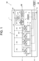
- FIG. 1 is an explanation diagram illustrating a schematic configuration of a fuel cell system 100 according to one embodiment of the present invention.
- a solid arrow indicates a fluid passage (in particular, for example, a pipe) and a flow direction of a fluid flowing in the fluid passage.
- a broken line indicates wiring.
- the configuration and control of the present embodiment can also be applied to a system in which a fuel gas other than hydrogen (for example, a gas containing methane as a main component) is used to generate electric power.
- a fuel gas other than hydrogen for example, a gas containing methane as a main component
- the fuel cell system 100 described in the present embodiment is, although not particularly limited, suitable for use in, for example, a ship, and is also suitable for use on land (stationary use).
- the fuel cell system 100 includes a housing 1.
- the housing 1 has a rectangular parallelepiped shape as one example, the housing 1 may have another shape.
- the housing 1 includes a first section 11, a second section 12, and a partition wall 13.
- the first section 11 and the second section 12 are arranged adjacent to each other.
- the first section 11 and the second section 12 are aligned vertically.
- the first section 11 is arranged above the second section 12.
- the configuration in which the first section 11 and the second section 12 are aligned vertically is an example, and another configuration may be adopted.
- the first section and the second section may be aligned side by side.
- the partition wall 13 separates the first section 11 and the second section 12.
- the partition wall 13 constitutes a bottom wall of the first section 11.
- the partition wall 13 constitutes an upper wall of the second section 12. That is, the partition wall 13 is a wall commonly used by the first section 11 and the second section 12.
- fuel cell modules 2 are disposed in the first section 11.
- four fuel cell modules 2 are accommodated in the first section 11. Note that only one fuel cell module 2 may be accommodated in the housing 1, or any number of (other than four) fuel cell modules 2 may be accommodated in the housing.
- the fuel cell module 2 includes a fuel cell stack 2a. That is, the fuel cell system 100 of the present embodiment includes a fuel cell stack 2a. In addition, the fuel cell module 2 includes a boost converter, a compressor for blowing air, and a pump for circulating a cooling liquid (all of which are not shown).
- the fuel cell stack 2a is constituted by a plurality of stacked cells. Each cell includes a solid polymer electrolyte membrane, an anode electrode, a cathode electrode, and a pair of separators. The solid polymer electrolyte membrane is disposed between the anode electrode and the cathode electrode.
- the anode electrode is a negative electrode (fuel electrode).
- the anode electrode includes an anode catalyst layer and a gas diffusion layer.
- the cathode electrode is a positive electrode (air electrode).
- the cathode electrode includes a cathode catalyst layer and a gas diffusion layer.
- the anode electrode, the solid polymer electrolyte membrane, and the cathode electrode constitute a membrane electrode assembly (MEA).
- MEA membrane electrode assembly
- the membrane-electrode assembly is disposed between the pair of separators.
- Each separator has a plurality of grooves. Each groove of one of the pair of separators forms a flow path of a hydrogen gas.
- Each groove of the other of the pair of separators forms a flow path of an oxidant gas (for example, air).
- the fuel cell module 2 has a hydrogen circulation pump 2b.
- the hydrogen circulation pump 2b is provided to return excess hydrogen that has not been used for electric power generation in the fuel cell stack 2a to the fuel cell stack 2a. Thus, the excess hydrogen may be reused in the fuel cell stack 2a.
- the fuel cell module 2 has an injector 21a.
- the injector 21a reduces the pressure of hydrogen (fuel gas) and supplies the hydrogen to the fuel cell stack 2a.
- the injector 21a is one example of a below-described pressure reduction portion 21 (see FIG. 9 ).
- the above-described injector 21a may be a pressure regulating valve having a shut-off function.
- the fuel cell module 2 may not include the injector 21a. In this case, the operating pressure of the fuel cell stack 2a is the same as the operating pressure of a below-described individual pipe 33.
- a fuel gas system 3 is disposed in the first section 11. That is, the fuel cell system 100 of the present embodiment includes the fuel gas system 3.
- the fuel gas system 3 supplies hydrogen (fuel gas) to the fuel cell stack 2a of the fuel cell module 2.
- the fuel gas system 3 includes a fuel gas supply pipe 31, a branch portion 32, and an individual pipe 33.
- the branch portion 32 connects the fuel gas supply pipe 31 and four individual pipes 33.
- Each of the four individual pipes 33 is connected to the fuel cell module 2.
- Hydrogen that has entered the fuel gas supply pipe 31 in the housing 1 from an external hydrogen supply passage 300 reaches the branch portion 32 via a below-described valve device 5, and is distributed to the four individual pipes 33 at the branch portion 32. Then, the hydrogen flowing through each individual pipe 33 is supplied to each fuel cell module 2.
- a vent portion 4 is further disposed in the first section 11.
- the vent portion 4 includes a common vent passage 41 and an individual vent passage 42.
- the common vent passage 41 and the individual vent passages 42 can be constituted by pipes. Unnecessary hydrogen discharged from each fuel cell module 2 is sent to the common vent passage 41 via each individual vent passage 42. Then, the hydrogen is discharged from the atmosphere opening port 43 via a below-described vent system 44 connected to the common vent passage 41.
- the atmosphere opening port 43 is provided on a side surface of the housing 1, the atmosphere opening port 43 may be provided on another surface (for example, an upper surface) of the housing 1.
- another pipe external vent passage
- hydrogen may be discharged to an appropriate place outside the housing 1 through this another pipe.
- hydrogen flowing through each individual vent passage 42 may be directly discharged to the outside of the housing 1 (without passing through the common vent passage 41).
- the vent portion 4 further includes a vent system 44. That is, the fuel cell system 100 of the present embodiment includes the vent system 44.
- the vent system 44 is a pipe that is branched from the fuel gas system 3 between an upstream-side block valve 51 and a downstream-side block valve 52 of a below-described valve device 5 and is connected to the atmosphere opening port 43.
- the above-described common vent passage 41 is connected to the vent system 44.
- the upstream-side block valve 51 may be provided outside the housing 11.
- a valve device 5 that is referred to as DBB is further disposed in the first section 11.
- the valve device 5 includes an upstream-side block valve 51, a downstream-side block valve 52, and a bleed valve 53.
- the upstream-side block valve 51 and the downstream-side block valve 52 are valves that are provided in the fuel gas system 3 (in particular, the fuel gas supply pipe 31) to open and close (open or block) the fuel gas system 3.
- the upstream-side block valve 51 and the downstream-side block valve 52 are arranged in this order from the upstream side in a direction in which hydrogen flows through the fuel gas supply pipe 31. Therefore, the downstream-side block valve 52 is positioned between the upstream-side block valve 51 and the fuel cell module 2.
- the bleed valve 53 is a valve that opens and closes the above-described vent system 44.
- the fuel cell system 100 includes the upstream-side block valve 51, the downstream-side block valve 52, the vent system 44, and the bleed valve 53.
- the sensors 6 include a hydrogen sensor for detecting hydrogen concentration, a pressure sensor for detecting pressure in the pipe, and a temperature sensor for detecting temperature at a predetermined position, etc. These sensors 6 are arranged at appropriate positions in the first section 11.
- the above-described auxiliary machine includes a switchboard 15.
- the switchboard 15 is a portion through which wiring is taken out from the inside of the housing 1 to the outside and wiring is inserted from the outside to the inside.
- the switchboard 15 includes various terminals and relays. Further, the switchboard 15 includes a connection portion between wiring inside the housing 1 and wiring outside the housing 1.
- the wiring inside the housing 1 includes an electric power line through which electric power generated by the fuel cell module 2 flows, a control line for controlling the fuel cell module 2, and a sensor line connected to the various sensors 6.
- the wiring is disposed across the first section 11 and the second section 12 via a seal portion (not shown) provided in the partition wall 13.
- the switchboard 15 is connected to a control device 500 disposed outside the housing 1 via a communication line CL.
- a wired line such as a cable can be used as the communication line CL.
- the communication line CL may include a wireless network so that the housing 1 and the control device 500 can communicate with each other wirelessly.
- the control device 500 is a device that controls operation of each portion in the housing 1. That is, the fuel cell system 100 of the present embodiment includes the control device 500.
- the control device 500 is constituted by, for example, a programmable logic controller (PLC). By sending a control signal from the control device 500 to the switchboard 15 of the housing 1 via the communication line CL, each portion in the housing 1 can be controlled.
- PLC programmable logic controller
- the control device 500 may be disposed in the housing 1 (for example, in the switchboard 15) and may be remotely controlled from the outside to control each portion of the housing 1.
- an air intake portion, a heat exchanger, etc. are also disposed in the second section 12.
- the air intake portion takes in air to be supplied to the air electrode of the fuel cell stack 2a.
- the heat exchanger is provided to cool the fuel cell module 2 by using a coolant.
- the air intake portion and the heat exchanger are provided correspondingly to each fuel cell module 2.
- a flow path of air flowing from the air intake portion toward the fuel cell module 2 and a flow path of the coolant circulating between the heat exchanger and the fuel cell module are disposed across the first section 11 and the second section 12 via a seal portion (not shown) provided in the partition wall 13.
- the pressure in the fuel gas system 3 is reduced by controlling opening and closing timings of each valve (the upstream-side block valve 51, the downstream-side block valve 52, and the bleed valve 53) of the valve device 5 as follows.
- the control device 500 conducts the pressure reduction control. That is, the opening and closing of each valve of the valve device 5 are controlled based on the control signal sent from the control device 500.
- the pressure reduction control of the present embodiment will be described below.
- the operation stop of the fuel cell stack 2a can also be considered as a stop of an operation of the fuel cell module 2, that is, a stop of an electric power generation by the fuel cell module 2.
- FIG. 2 is a flowchart illustrating a flow of an operation of pressure reduction control in the embodiment.
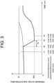
- FIG. 3 is a graph schematically illustrating changes in the pressure in a fuel gas system 3 (in this case, in a pipe on a downstream-side of the downstream-side block valve 52) with and without the pressure reduction control.
- a thick line graph indicates a pressure change when the pressure reduction control of the present embodiment is performed
- a thin line graph indicates a pressure change when the above-described pressure reduction control is not performed.
- the various sensors 6 constantly or periodically detect the hydrogen concentration and the like in the first section 11.
- a detection signal from the sensor 6 is output to the control device 500 via the switchboard 15 (S 1).
- the upstream-side block valve 51 and the downstream-side block valve 52 of the valve device 5 are opened and the bleed valve 53 is closed.
- the control device 500 sends a control signal to the housing 1 to close the upstream-side block valve 51 of the valve device 5 (S3).
- the time at which the upstream-side block valve 51 is closed is referred to as t1.
- the case where there is a request to stop the fuel cell system 100 refers to a case where there is a normal stop operation for stopping electric power generation in the fuel cell system 100 on the control device 500 side, and a case where a value detected in the sensor 6 is a value indicating an abnormality and the control device 500 determines that it is necessary to stop the fuel cell system 100.
- the control device 500 sends a control signal to the housing 1 to open the bleed valve 53 of the valve device 5 (S4).
- the time at which the bleed valve 53 is opened is referred to as t2.
- the bleed valve 53 is opened, hydrogen remaining in the pipe on the downstream side of the upstream-side block valve 51 in the fuel gas system 3 flows through the vent system 44 and is discharged to the outside of the housing 1 via the atmosphere opening port 43. Therefore, as shown in FIG. 3 , the pressure in the pipe of the fuel gas system 3 (particularly, the pressure on the downstream side of the upstream-side block valves 51) decreases with time after the time t2.
- the control device 500 waits until the predetermined time Tp elapses from the time t2 (No in S5), and when the predetermined time Tp elapses from the time t2 (Yes in S5), the control device 500 sends a control signal to the housing 1 to close the downstream-side block valves 52 of the valve device 5 (S6).
- the time at which the downstream-side block valve 52 is closed is referred to as t3.
- the control device 500 sends a control signal to the housing 1 to close the bleed valve 53 (S7).
- the time at which the bleed valve 53 is closed is referred to as t4.
- the control device 500 when the operation of the fuel cell stack 2a is stopped, the control device 500 performs the below-described pressure reduction control. That is, the bleed valve 53 is opened (S3 and S4) after the upstream-side block valves 51 is closed, and the downstream-side block valve 52 is closed (S5 and S6) after the predetermined time Tp elapses from the opening of the bleed valve 53.
- the design pressure Pr of the pipe of the fuel gas system 3 is 0.99 MPaG
- the supply pressure is 0.90 MPaG (10 °C) on the assumption that the fuel gas remains in the pipe at the supply pressure.
- the above-mentioned “G” represents a gauge pressure based on the atmospheric air pressure (0.101325 MPa as an absolute value) (the same applies hereinafter).
- the pressure in the pipe becomes 1.006 MPaG and exceeds the above-described design pressure Pr (see the thin line graph in FIG. 3 ).
- the downstream-side block valve 52 is closed after the pressure in the pipe of the fuel gas system 3 between the downstream-side block valve 52 and the fuel cell stack 2a is made sufficiently smaller than the design pressure Pr of the fuel gas system 3.
- the possibility that the pressure in the fuel gas system 3 exceeds the design pressure Pr is reduced (see the thick line graph in FIG. 3 ).
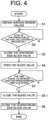
- FIG. 4 is a flowchart illustrating a flow of an operation of another pressure reduction control of the embodiment.
- the pressure reduction control in FIG. 4 is the same as the pressure reduction control in FIG. 2 except that the bleed valve 53 is closed first in S5-1 after S5, and then the downstream-side block valve 52 is closed in S6.
- the bleed valve 53 When the bleed valve 53 is kept open after the S4, air (gas other than fuel gas) outside the housing 1 enters the fuel gas system 3 on the downstream side of the downstream-side block valve 52 via the atmosphere opening port 43 and the vent system 44.
- the reason why the bleed valve 53 is opened in S4 is to release the pressure in the pipe of the fuel gas system 3 on the downstream side of the downstream-side block valve 52. Since this object is achieved by the elapse of the predetermined time Tp from the opening of the bleed valve 53, it is desirable to close the bleed valve 53 early after S5 to reduce the amount of air entering the fuel gas system 3. From this viewpoint, as shown in FIG. 4 , in the above-described pressure reduction control, the bleed valve 53 may be closed before the downstream-side block valve 52 is closed (see S5-1 and S6).
- FIG. 5 is a flowchart illustrating a flow of an operation of still another pressure reduction control of the embodiment.
- the pressure reduction control in FIG. 5 is the same as the pressure reduction control in FIG. 2 except that, in S6-1 after S5, the downstream-side block valve 52 is closed simultaneously with the closing of the bleed valve 53.
- the bleed valve 53 may be closed simultaneously with the closing of the downstream-side block valve 52 (see S6-1).
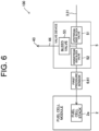
- FIG. 6 is a block diagram schematically illustrating another configuration of the fuel cell system 100 of the present embodiment.
- the fuel cell system 100 may include a first pressure sensor 61 as the sensor 6.
- the first pressure sensor 61 is disposed in the fuel gas system 3 between the upstream-side block valve 51 and the fuel cell stack 2a.
- the predetermined time Tp in S5 in FIG. 2 may be a time until the measurement value of the first pressure sensor 61 becomes equal to or less than a preset setting value Pth.
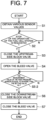
- FIG. 7 is a flowchart illustrating a flow of an operation of pressure reduction control in the fuel cell system 100 provided with the configuration illustrated in FIG. 6 .
- the pressure reduction control in FIG. 7 is the same as the pressure reduction control in FIG. 2 except that S5 is replaced by S5-2.
- the control device 500 sends a control signal to the housing 1 to close the downstream-side block valve 52 (S6).
- the predetermined time Tp is set as described above and the measurement value of the first pressure sensor 61 becomes equal to or less than the setting value Pth after S4, the predetermined time Tp has elapsed from the opening of the bleed valve 53 in S4. Therefore, by closing the downstream-side block valves 52 in S6 after S5-2, it is possible to reduce the possibility that, similarly to the pressure reduction control in FIG. 2 , the pressure in the fuel gas system 3 exceeds the design pressure Pr of the fuel gas system 3 due to an increase in the ambient temperature.
- the pressure in the fuel gas system 3 between the downstream-side block valve 52 and the fuel cell stack 2a is directly measured.
- the first pressure sensor 61 is disposed between the downstream-side block valve 52 and the fuel cell stack 2a in the fuel gas system 3.
- FIG. 8 is a block diagram schematically illustrating still another configuration of the fuel cell system 100 of the present embodiment.
- the above-described first pressure sensor 61 may be disposed on the downstream side of the upstream-side block valve 51 and on the upstream side of the downstream-side block valve 52 in the fuel gas system 3.
- the pressure in the closed space surrounded by the upstream-side block valve 51, the downstream-side block valve 52, and the bleed valve 53 in the fuel gas system 3 and the vent system 44 can be detected by the first pressure sensor 61 after all of the upstream-side block valve 51, the downstream-side block valve 52, and the bleed valve 53 are closed.
- the pressure in the above-described closed space decreases with the elapse of time, it is found that there is a possibility that the fuel gas leaks from any one of the valves or a joint between the valve and the pipe.
- the first pressure sensor 61 may be disposed between the upstream-side block valve 51 and the downstream-side block valve 52 in the fuel gas system 3 in that a leak check for detecting the presence or absence of leakage of the fuel gas can be performed by monitoring a change in the pressure in the shielded space.
- FIG. 9 is a block diagram schematically illustrating still another configuration of the fuel cell system 100 of the present embodiment.
- the fuel cell module 2 includes a pressure reduction portion 21 and a relief valve 22 in addition to the fuel cell stack 2a.
- the other configuration of FIG. 9 is the same as that of FIG. 6 .
- the pressure reduction portion 21 is disposed between the downstream-side block valve 52 and the fuel cell stack 2a in the fuel gas system 3.
- the pressure reduction portion 21 is constituted by an injector that decompresses and injects hydrogen that has passed through the downstream-side block valve 52.
- the pressure reduction portion 21 reduces the pressure of hydrogen having a supply pressure of 0.9 MPaG that has passed through the downstream-side block valve 52 to 0.2 MpaG and supplies it to the fuel cell stack 2a.
- the relief valve 22 is disposed in a discharge flow path portion 23 branching from the fuel gas system 3 between the pressure reduction portion 21 and the fuel cell stack 2a.
- the discharge flow path portion 23 merges with the vent system 44 via the common vent passage 41 on the downstream side opposite to the relief valve 22.
- the discharge flow path portion 23 may be the same pipe as the individual vent passage 42 shown in FIG. 1 .
- the fuel cell system 100 of FIG. 9 includes the pressure reduction portion 21 and the relief valve 22.
- the pressure resistance of the fuel cell stack 2a is 0.6 MpaG.
- the relief valves 22 are opened to open the discharge flow path portion 23.
- the hydrogen passing through the pressure reduction portion 21 flows through the discharge flow path portion 23 and the common vent passage 41, joins the vent system 44, and is discharged from the atmosphere opening port 43 to the outside of the housing 1. Therefore, the relief valve 22 is configured to open in order to protect the fuel cell stack 2a when the pressure reduction portion 21 does not appropriately reduce the supply pressure of hydrogen, for example, when the pressure reduction portion 21 fails for some reason.
- the above-described relief valve 22 is configured of, for example, a mechanical valve.
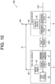
- FIG. 10 is a block diagram schematically illustrating still another configuration of the fuel cell system 100 of the present embodiment.
- the fuel cell module 2 further includes a second pressure sensor 62 in addition to the configuration of FIG. 9 . That is, the fuel cell system 100 of FIG. 10 includes the second pressure sensor 62.
- the second pressure sensor 62 is disposed between the pressure reduction portion 21 and the fuel cell stack 2a in the fuel gas system 3.
- the control device 500 of the present embodiment when the value of the second pressure sensor 62 becomes equal to or greater than a predetermined value (for example, 0.3 MpaG), closing of the upstream-side block valve 51 may be closed and the downstream-side block valve 52 and the bleed valves 53 may be opened.
- a predetermined value for example, 0.3 MpaG
- the pressure reduction portion 21 does not conduct pressure reduction of the supply pressure to a predetermined pressure (for example, 0.2 MpaG), and in this case, it can be determined that some abnormality (for example, failure) has occurred in the pressure reduction portion 21.
- a predetermined pressure for example, 0.2 MpaG
- some abnormality for example, failure
- the supply of the fuel gas to the fuel cell stack 2a is stopped by closing the upstream-side block valve 51, and thereby, it is possible to avoid a situation in which the fuel cell stack 2a is excessively boosted.
- the relief valve 22 can be made not to operate (not to open).
- the life of the relief valve 22 may be shortened in accordance with the number of times of operation. Further, when the mechanical relief valve 22 is operated, it takes time until the relief valve 22 is closed next time, and there is also a concern that the restoration is delayed. That is, when some abnormality occurs in the pressure reduction portion 21, by making the relief valve 22 not operate, it is possible to avoid a decrease in the operation life of the relief valve 22, and it is also possible to restore the relief valve 22 in a short time. From such a viewpoint, it is desirable to control the opening and closing of the upstream-side block valve 51, the downstream-side block valve 52, and the bleed valve 53 based on the value of the second pressure sensor 62 as described above.
- FIG. 11 is a block diagram schematically illustrating still another configuration of the fuel cell system 100 of the present embodiment.
- the fuel cell system 100 shown in FIG. 11 further includes a drain portion 45.
- the drain portion 45 communicates with the vent system 44 between the bleed valve 53 and the atmosphere opening port 43.
- the above-described drain portion 45 includes a drain pipe 451 connected to the vent system 44 and a drain valve 452 that opens and closes the drain pipe 451.
- the control of opening and closing of the drain valve 452 is performed based on a control signal from the control device 500.
- the condensed water (dew condensation water) can be discharged from the drain portion 45.
- the condensed water can be discharged to a predetermined place via the drain pipe 451. Therefore, the condensed water is prevented from flowing into the bleed valve 53 side. From the viewpoint of preventing such backflow of the condensed water to the vent system 44, it is desirable to provide the drain portion 45 communicating with the vent system 44.
- FIG. 12 is a block diagram schematically illustrating still another configuration of the fuel cell system 100 of the present embodiment.
- the vent system 44 includes a condensed water backflow preventing portion 46.
- the condensed water backflow preventing portion 46 is formed by bending a part of the vent system 44 into a shape recessed downward.
- the fuel cell system 100 further includes an inert gas supply passage 71.
- the inert gas supply passage 71 is connected to the fuel gas system 3 on the upstream side of the upstream-side block valve 51. Nitrogen as an inert gas is supplied to the inert gas supply passage 71. Note that the inert gas is not limited to the above-mentioned nitrogen, and may be argon or the like.
- a switching valve (not shown) is disposed in a merging portion 72 that is a connection portion between the inert gas supply passage 71 and the fuel gas system 3. By appropriately controlling the opening and closing of the switching valve based on the control signal from the control device 500 (see FIG. 1 ), it is possible to switch between the introduction of the inert gas from the inert gas supply passage 71 to the fuel gas system 3 and the stop of the introduction.
- a check valve (not shown) is also disposed in the inert gas supply passage 71.
- the drying control may be performed after the above-described pressure reduction control in a state in which the operation of the fuel cell stack 2a is stopped based on the control signal from the control device 500.
- the inert gas supplied from the inert gas supply passage 71 is guided to the condensed water backflow preventing portion 46.
- the condensed water When moisture is condensed in the vent system 44 to cause dew condensation, the condensed water can be prevented from flowing into the bleed valve 53 side by guiding the inert gas to the condensed water backflow preventing portion 46 to cause the condensed water to stay in the condensed water backflow preventing portion 46. Further, the condensed water staying in the condensed water backflow preventing portion 46 is dried and evaporated by applying an inert gas, and can be discharged from the atmosphere opening port 43. Therefore, as shown in FIG. 11 , it is desirable that the control device 500 performs the above-described drying control in that the condensed water can be vaporized and easily discharged without providing the drain portion 45 and the discharge route of the condensed water.
- the inert gas supplied from the inert gas supply passage 71 can be guided to the vent system 44 and the condensed water backflow preventing portion 46, and can be reliably applied to the condensed water. That is, in the above-described drying control, the inert gas is supplied from the inert gas supply passage 71 in a state in which the upstream-side block valve 51 and the bleed valve 53 are opened and the downstream-side block valve 52 is closed.
- FIG. 13 is a block diagram schematically illustrating still another configuration of the fuel cell system 100 of the present embodiment.
- the fuel cell system 100 shown in FIG. 13 further includes a purge system 47 in addition to the configuration of FIG. 12 .
- the purge system 47 branches off from the fuel gas system 3 at a position on the downstream side of the merging portion 72 between the fuel gas system 3 and the inert gas supply passage 71 and on the upstream side of the upstream-side block valve 51, and joins the vent system 44.
- the above-described purge system 47 includes a purge passage 471 and a purge valve 472.
- the purge passage 471 connects the fuel gas system 3 and the vent system 44.
- the purge valve 472 opens and closes the purge passage 471. The control of opening and closing of the purge valve 472 is performed based on the control signal from the control device 500.
- the inert gas supplied from the inert gas supply passage 71 can be guided to the vent system 44 via the purge passage 471.
- the upstream-side block valve 51 is closed, the condensed water staying in the condensed water backflow preventing portion 46 is dried and evaporated by applying an inert gas, and can be discharged from the atmosphere opening port 43.
- the inert gas does not enter the downstream side of the upstream-side block valve 51 in the fuel gas system 3.
- the inert gas has entered the downstream side of the upstream-side block valves 51, it is necessary to push out the inert gas when the purge is performed with the fuel gas (for example, when the electric power generation is restarted in the fuel cell stack 2a), and the amount of the fuel gas used for the purge increases accordingly.
- the valve device 5 and the purge valve 472 as follows, it is possible to reliably reduce the entry of the inert gas to the downstream side of the upstream-side block valves 51. That is, in the above-described drying control, after the purge valve 472 is opened in a state in which all of the upstream-side block valve 51, the downstream-side block valve 52, and the bleed valve 53 are closed, the inert gas is supplied from the inert gas supply passage 71.
- FIGS. 4 and 5 The configurations and controls illustrated in the drawings can be combined as appropriate.
- the timing of closing the bleed valve 53 and the downstream-side block valve 52 shown in FIGS. 4 and 5 can be applied to all the pressure reduction controls.
- the configurations shown in FIGS. 11 to 13 can be applied to any of FIGS. 6 and 8 to 10.
- the fuel cell system described in the present embodiment can also be expressed as a fuel cell system described in the following appendices.
- a fuel cell system of appendix (1) includes: a fuel cell module having a fuel cell stack; a fuel gas system that supplies a fuel gas to the fuel cell stack; an upstream-side block valve and a downstream-side block valve that open and close the fuel gas system; a vent system that is provided to branch from the fuel gas system between the upstream-side block valve and the downstream-side block valve; and a bleed valve that opens and closes the vent system, wherein when an operation of the fuel cell stack is to be stopped, pressure reduction control, in which the bleed valve is opened after the upstream-side block valve is closed, and then the downstream-side block valve is closed after a predetermined time has elapsed, is performed.
- a fuel cell system of appendix (2) is the fuel cell system according to appendix (1), wherein, in the pressure reduction control, the bleed valve is closed before the downstream-side block valve is closed.
- a fuel cell system of appendix (3) is the fuel cell system according to appendix (1), wherein, in the pressure reduction control, the bleed valve is closed simultaneously with closing of the downstream-side block valve.
- a fuel cell system of appendix (4) is the fuel cell system according to any one of appendices (1) to (3), further comprising a first pressure sensor disposed in the fuel gas system between the upstream-side block valve and the fuel cell stack, wherein the predetermined time is a time until a measurement value of the first pressure sensor becomes equal to or less than a preset setting value.
- a fuel cell system of appendix (5) is the fuel cell system according to appendix (4), wherein the first pressure sensor is disposed between the downstream-side block valve and the fuel cell stack in the fuel gas system.
- a fuel cell system of appendix (6) is the fuel cell system according to appendix (4), wherein the first pressure sensor is disposed between the upstream-side block valve and the downstream-side block valve in the fuel gas system.
- a fuel cell system of appendix (7) is the fuel cell system according to appendices (1) to (6), further comprising: a pressure reduction portion disposed between the downstream-side block valve and the fuel cell stack in the fuel gas system; and a relief valve disposed in a discharge flow path portion that branches from the fuel gas system between the pressure reduction portion and the fuel cell stack, wherein the discharge flow path portion merges with the vent system on a downstream side opposite to the relief valve.
- a fuel cell system of appendix (8) is the fuel cell system according to appendix (7), further comprising: a second pressure sensor disposed between the pressure reduction portion and the fuel cell stack in the fuel gas system, wherein, in the pressure reduction control, the upstream-side block valve is closed and the downstream-side block valve and the bleed valve are opened when a value of the second pressure sensor becomes equal to or greater than a predetermined value.
- a fuel cell system of appendix (9) is the fuel cell system according to any one of appendices (1) to (8), further comprising a drain portion that communicates with the vent system between the bleed valve and the atmosphere opening port.
- a fuel cell system of appendix (10) is the fuel cell system according to appendices (1) to (9), further comprising: an inert gas supply passage connected to the fuel gas system, wherein the vent system includes a condensed water backflow preventing portion, and a drying control for guiding an inert gas supplied from the inert gas supply passage to the condensed water backflow preventing portion is performed in a state in which an operation of the fuel cell stack is stopped.
- a fuel cell system of appendix (11) is the fuel cell system according to appendix (10), wherein in the drying control, the inert gas is supplied from the inert gas supply passage in a state in which the upstream-side block valve and the bleed valve are opened and the downstream-side block valve is closed.
- a fuel cell system of appendix (12) is the fuel cell system according to appendix (10), further comprising: a purge system that branches off from the fuel gas system at a position on a downstream side of a merging portion between the fuel gas system and the inert gas supply passage and on an upstream side of the upstream-side block valve, and joins the vent system, wherein the purge system includes a purge passage and a purge valve.
- a fuel cell system of appendix (13) is the fuel cell system according to appendix (12), wherein in the drying control, the inert gas is supplied from the inert gas supply passage after the purge valve is opened in a state in which all of the upstream-side block valve, the downstream-side block valve, and the bleed valve are closed.
- the fuel cell system of the present invention can be used to generate electric power on a ship or on land, for example.
Landscapes
- Life Sciences & Earth Sciences (AREA)
- Engineering & Computer Science (AREA)
- Manufacturing & Machinery (AREA)
- Sustainable Development (AREA)
- Sustainable Energy (AREA)
- Chemical & Material Sciences (AREA)
- Chemical Kinetics & Catalysis (AREA)
- Electrochemistry (AREA)
- General Chemical & Material Sciences (AREA)
- Fuel Cell (AREA)
Abstract
Description
- The present invention relates to a fuel cell system.
- Conventionally, a fuel cell system provided with a valve device called DBB (double block and bleed) has been disclosed. For example, in the fuel cell system of
Patent Document 1, when the operation of the fuel cell device is stopped, two shutoff valves (block valves) disposed in a fuel gas supply path are closed, and a space between the two shutoff valves is opened by opening a bleed valve, and thereby, the supply of the fuel gas to the fuel cell device is stopped. - Patent Document 1:
JP 2020-9544 A - When the two shutoff valves are simultaneously closed to stop the supply of the fuel gas, the fuel gas remains in a pipe between the shutoff valve on the downstream side and a fuel cell stack or a fuel cell module (a module including the fuel cell stack) included in the fuel cell device in the fuel gas supply path (fuel gas system) at a pressure that is a pressure during normal operation of the fuel cell stack or the fuel cell module. Therefore, for example, in a case where the difference between the supply pressure of the fuel gas and the design pressure of the pipe is small, when the ambient temperature rises while the operation of the fuel cell stack or the fuel cell module is stopped, the fuel gas in the pipe expands, and the pressure in the pipe may exceed the design pressure.
- The present invention has been made to solve the above-described problem, and an object of the present invention is to provide a fuel cell system capable of reducing the possibility that the pressure in the fuel gas system exceeds the design pressure of the fuel gas system even when the ambient temperature rises and the pressure in the fuel gas system rises while the operation of the fuel cell stack or the fuel cell module is stopped.
- A fuel cell system according to one aspect of the present invention includes a fuel cell module having a fuel cell stack; a fuel gas system for supplying fuel gas to the fuel cell stack; an upstream-side block valve and a downstream-side block valve that open and close the fuel gas system; a vent system that is provided to branch from the fuel gas system between the upstream-side block valve and the downstream-side block valve; and a bleed valve that opens and closes the vent system, in which when an operation of the fuel cell stack is to be stopped, pressure reduction control, in which the bleed valve is opened after the upstream-side block valve is closed, and then the downstream-side block valve is closed after a predetermined time has elapsed, is performed.
- According to the above-described configuration, even when the ambient temperature rises and the pressure in the fuel gas system rises while the operation of the fuel cell stack or the fuel cell module is stopped, it is possible to reduce the possibility that the pressure in the fuel gas system exceeds the design pressure of the fuel gas system.
-
-
FIG. 1 is an explanation diagram illustrating a schematic configuration of a fuel cell system according to one embodiment of the present invention. -
FIG. 2 is a flowchart illustrating a flow of an operation of pressure reduction control in the fuel cell system. -
FIG. 3 is a graph schematically illustrating change in pressure in a fuel gas system with and without the pressure reduction control. -
FIG. 4 is a flowchart illustrating a flow of an operation of another pressure reduction control. -
FIG. 5 is a flowchart illustrating a flow of an operation of still another pressure reduction control. -
FIG. 6 is a block diagram schematically illustrating another configuration of the fuel cell system. -
FIG. 7 is a flowchart illustrating a flow of an operation of pressure reduction control in the fuel cell system provided with the configuration illustrated inFIG. 6 . -
FIG. 8 is a block diagram schematically illustrating still another configuration of the fuel cell system. -
FIG. 9 is a block diagram schematically showing still another configuration of the fuel cell system. -
FIG. 10 is a block diagram schematically showing still another configuration of the fuel cell system. -
FIG. 11 is a block diagram schematically showing still another configuration of the fuel cell system. -
FIG. 12 is a block diagram schematically showing still another configuration of the fuel cell system. -
FIG. 13 is a block diagram schematically showing still another configuration of the fuel cell system. - Embodiments of the present invention are described with reference to the drawings. In the drawings, the same or corresponding parts are denoted by the same reference characters, and a description thereof will not be repeated unless otherwise required.
-
FIG. 1 is an explanation diagram illustrating a schematic configuration of afuel cell system 100 according to one embodiment of the present invention. InFIG. 1 , a solid arrow indicates a fluid passage (in particular, for example, a pipe) and a flow direction of a fluid flowing in the fluid passage. InFIG. 1 , a broken line indicates wiring. - In the present embodiment, an example in which hydrogen is used as a fuel gas used in the
fuel cell system 100 will be described. However, the configuration and control of the present embodiment can also be applied to a system in which a fuel gas other than hydrogen (for example, a gas containing methane as a main component) is used to generate electric power. In addition, thefuel cell system 100 described in the present embodiment is, although not particularly limited, suitable for use in, for example, a ship, and is also suitable for use on land (stationary use). - As shown in
FIG. 1 , thefuel cell system 100 includes ahousing 1. Although thehousing 1 has a rectangular parallelepiped shape as one example, thehousing 1 may have another shape. Thehousing 1 includes afirst section 11, asecond section 12, and apartition wall 13. - The
first section 11 and thesecond section 12 are arranged adjacent to each other. In the present embodiment, thefirst section 11 and thesecond section 12 are aligned vertically. Thefirst section 11 is arranged above thesecond section 12. Note that the configuration in which thefirst section 11 and thesecond section 12 are aligned vertically is an example, and another configuration may be adopted. For example, the first section and the second section may be aligned side by side. - The
partition wall 13 separates thefirst section 11 and thesecond section 12. Thepartition wall 13 constitutes a bottom wall of thefirst section 11. Thepartition wall 13 constitutes an upper wall of thesecond section 12. That is, thepartition wall 13 is a wall commonly used by thefirst section 11 and thesecond section 12. - As shown in
FIG. 1 ,fuel cell modules 2 are disposed in thefirst section 11. In the present embodiment, fourfuel cell modules 2 are accommodated in thefirst section 11. Note that only onefuel cell module 2 may be accommodated in thehousing 1, or any number of (other than four)fuel cell modules 2 may be accommodated in the housing. - The
fuel cell module 2 includes afuel cell stack 2a. That is, thefuel cell system 100 of the present embodiment includes afuel cell stack 2a. In addition, thefuel cell module 2 includes a boost converter, a compressor for blowing air, and a pump for circulating a cooling liquid (all of which are not shown). Thefuel cell stack 2a is constituted by a plurality of stacked cells. Each cell includes a solid polymer electrolyte membrane, an anode electrode, a cathode electrode, and a pair of separators. The solid polymer electrolyte membrane is disposed between the anode electrode and the cathode electrode. The anode electrode is a negative electrode (fuel electrode). The anode electrode includes an anode catalyst layer and a gas diffusion layer. The cathode electrode is a positive electrode (air electrode). The cathode electrode includes a cathode catalyst layer and a gas diffusion layer. The anode electrode, the solid polymer electrolyte membrane, and the cathode electrode constitute a membrane electrode assembly (MEA). The membrane-electrode assembly is disposed between the pair of separators. Each separator has a plurality of grooves. Each groove of one of the pair of separators forms a flow path of a hydrogen gas. Each groove of the other of the pair of separators forms a flow path of an oxidant gas (for example, air). - On the anode electrode side, hydrogen is catalytically split into hydrogen ions and electrons. The hydrogen ions pass through the solid polymer electrolyte membrane and move to the cathode electrode side. On the other hand, the electrons
- move to the cathode electrode side through an external circuit. As a result, current is generated (electric power is generated). On the cathode electrode side, oxygen contained in the oxidant gas combines with the electrons that have flowed through the external circuit and the hydrogen ions that have passed through the solid polymer electrolyte membrane to produce water. The produced water is discharged with an exhaust gas to the outside of the
fuel cell system 100. The electric power generated by thefuel cell stack 2a is boosted by the boost converter and extracted to the outside of thefuel cell system 100. - The
fuel cell module 2 has ahydrogen circulation pump 2b. Thehydrogen circulation pump 2b is provided to return excess hydrogen that has not been used for electric power generation in thefuel cell stack 2a to thefuel cell stack 2a. Thus, the excess hydrogen may be reused in thefuel cell stack 2a. - The
fuel cell module 2 has aninjector 21a. Theinjector 21a reduces the pressure of hydrogen (fuel gas) and supplies the hydrogen to thefuel cell stack 2a. Theinjector 21a is one example of a below-described pressure reduction portion 21 (seeFIG. 9 ). The above-describedinjector 21a may be a pressure regulating valve having a shut-off function. Further, thefuel cell module 2 may not include theinjector 21a. In this case, the operating pressure of thefuel cell stack 2a is the same as the operating pressure of a below-describedindividual pipe 33. - A fuel gas system 3 is disposed in the
first section 11. That is, thefuel cell system 100 of the present embodiment includes the fuel gas system 3. The fuel gas system 3 supplies hydrogen (fuel gas) to thefuel cell stack 2a of thefuel cell module 2. - More specifically, the fuel gas system 3 includes a fuel gas supply pipe 31, a
branch portion 32, and anindividual pipe 33. Thebranch portion 32 connects the fuel gas supply pipe 31 and fourindividual pipes 33. Each of the fourindividual pipes 33 is connected to thefuel cell module 2. Hydrogen that has entered the fuel gas supply pipe 31 in thehousing 1 from an externalhydrogen supply passage 300 reaches thebranch portion 32 via a below-describedvalve device 5, and is distributed to the fourindividual pipes 33 at thebranch portion 32. Then, the hydrogen flowing through eachindividual pipe 33 is supplied to eachfuel cell module 2. - A
vent portion 4 is further disposed in thefirst section 11. Thevent portion 4 includes acommon vent passage 41 and anindividual vent passage 42. Thecommon vent passage 41 and theindividual vent passages 42 can be constituted by pipes. Unnecessary hydrogen discharged from eachfuel cell module 2 is sent to thecommon vent passage 41 via eachindividual vent passage 42. Then, the hydrogen is discharged from theatmosphere opening port 43 via a below-describedvent system 44 connected to thecommon vent passage 41. - Although, in
FIG. 1 , theatmosphere opening port 43 is provided on a side surface of thehousing 1, theatmosphere opening port 43 may be provided on another surface (for example, an upper surface) of thehousing 1. In addition, another pipe (external vent passage) may be additionally connected to theatmosphere opening port 43, and hydrogen may be discharged to an appropriate place outside thehousing 1 through this another pipe. Further, hydrogen flowing through eachindividual vent passage 42 may be directly discharged to the outside of the housing 1 (without passing through the common vent passage 41). - The
vent portion 4 further includes avent system 44. That is, thefuel cell system 100 of the present embodiment includes thevent system 44. Thevent system 44 is a pipe that is branched from the fuel gas system 3 between an upstream-side block valve 51 and a downstream-side block valve 52 of a below-describedvalve device 5 and is connected to theatmosphere opening port 43. The above-describedcommon vent passage 41 is connected to thevent system 44. - From the viewpoint of preventing the pressure in the hydrogen pipe between a hydrogen inlet of the housing 1 (a connection portion between the
housing 1 and the external hydrogen supply passage 300) and the upstream-side block valve 51 from rising to the design pressure or higher, the upstream-side block valve 51 may be provided outside thehousing 11. - A
valve device 5 that is referred to as DBB is further disposed in thefirst section 11. Thevalve device 5 includes an upstream-side block valve 51, a downstream-side block valve 52, and ableed valve 53. The upstream-side block valve 51 and the downstream-side block valve 52 are valves that are provided in the fuel gas system 3 (in particular, the fuel gas supply pipe 31) to open and close (open or block) the fuel gas system 3. The upstream-side block valve 51 and the downstream-side block valve 52 are arranged in this order from the upstream side in a direction in which hydrogen flows through the fuel gas supply pipe 31. Therefore, the downstream-side block valve 52 is positioned between the upstream-side block valve 51 and thefuel cell module 2. Thebleed valve 53 is a valve that opens and closes the above-describedvent system 44. - When the
fuel cell module 2 is operated, hydrogen flowing through the fuel gas system 3 is supplied to thefuel cell module 2 by opening the upstream-side block valve 51 and the downstream-side block valve 52 and closing thebleed valve 53. Further, the supply of hydrogen to thefuel cell module 2 is stopped by closing the upstream-side block valve 51 and the downstream-side block valve 52. At this time, by opening thebleed valve 53, hydrogen accumulated in a space between the upstream-side block valve 51 and the downstream-side block valve 52 in the fuel gas system 3 (particularly, the fuel gas supply pipe 31) can be discharged to the outside of thehousing 1 via thevent system 44. - As described above, the
fuel cell system 100 according to the present embodiment includes the upstream-side block valve 51, the downstream-side block valve 52, thevent system 44, and thebleed valve 53. - Various sensors 6 are further disposed in the
first section 11. The sensors 6 include a hydrogen sensor for detecting hydrogen concentration, a pressure sensor for detecting pressure in the pipe, and a temperature sensor for detecting temperature at a predetermined position, etc. These sensors 6 are arranged at appropriate positions in thefirst section 11. - An auxiliary machine related to the operation of the
fuel cell module 2 is disposed in thesecond section 12. The above-described auxiliary machine includes aswitchboard 15. Theswitchboard 15 is a portion through which wiring is taken out from the inside of thehousing 1 to the outside and wiring is inserted from the outside to the inside. Theswitchboard 15 includes various terminals and relays. Further, theswitchboard 15 includes a connection portion between wiring inside thehousing 1 and wiring outside thehousing 1. - Here, the wiring inside the
housing 1 includes an electric power line through which electric power generated by thefuel cell module 2 flows, a control line for controlling thefuel cell module 2, and a sensor line connected to the various sensors 6. The wiring is disposed across thefirst section 11 and thesecond section 12 via a seal portion (not shown) provided in thepartition wall 13. Theswitchboard 15 is connected to acontrol device 500 disposed outside thehousing 1 via a communication line CL. For example, a wired line such as a cable can be used as the communication line CL. Note that the communication line CL may include a wireless network so that thehousing 1 and thecontrol device 500 can communicate with each other wirelessly. - The
control device 500 is a device that controls operation of each portion in thehousing 1. That is, thefuel cell system 100 of the present embodiment includes thecontrol device 500. Thecontrol device 500 is constituted by, for example, a programmable logic controller (PLC). By sending a control signal from thecontrol device 500 to theswitchboard 15 of thehousing 1 via the communication line CL, each portion in thehousing 1 can be controlled. Thecontrol device 500 may be disposed in the housing 1 (for example, in the switchboard 15) and may be remotely controlled from the outside to control each portion of thehousing 1. - In addition, an air intake portion, a heat exchanger, etc. are also disposed in the
second section 12. The air intake portion takes in air to be supplied to the air electrode of thefuel cell stack 2a. The heat exchanger is provided to cool thefuel cell module 2 by using a coolant. The air intake portion and the heat exchanger are provided correspondingly to eachfuel cell module 2. A flow path of air flowing from the air intake portion toward thefuel cell module 2 and a flow path of the coolant circulating between the heat exchanger and the fuel cell module are disposed across thefirst section 11 and thesecond section 12 via a seal portion (not shown) provided in thepartition wall 13. - In this embodiment, when the operation of the
fuel cell stack 2a is stopped due to a case in which, for example, the value detected by the sensor 6 is a value indicating abnormality, the pressure in the fuel gas system 3 is reduced by controlling opening and closing timings of each valve (the upstream-side block valve 51, the downstream-side block valve 52, and the bleed valve 53) of thevalve device 5 as follows. Thecontrol device 500 conducts the pressure reduction control. That is, the opening and closing of each valve of thevalve device 5 are controlled based on the control signal sent from thecontrol device 500. The pressure reduction control of the present embodiment will be described below. The operation stop of thefuel cell stack 2a can also be considered as a stop of an operation of thefuel cell module 2, that is, a stop of an electric power generation by thefuel cell module 2. -
FIG. 2 is a flowchart illustrating a flow of an operation of pressure reduction control in the embodiment.FIG. 3 is a graph schematically illustrating changes in the pressure in a fuel gas system 3 (in this case, in a pipe on a downstream-side of the downstream-side block valve 52) with and without the pressure reduction control. InFIG. 3 , a thick line graph indicates a pressure change when the pressure reduction control of the present embodiment is performed, and a thin line graph indicates a pressure change when the above-described pressure reduction control is not performed. - During the operation of the fuel cell module 2 (
fuel cell stack 2a), the various sensors 6 constantly or periodically detect the hydrogen concentration and the like in thefirst section 11. A detection signal from the sensor 6 is output to thecontrol device 500 via the switchboard 15 (S 1). In order to supply hydrogen to thefuel cell stack 2a during operation of thefuel cell stack 2a, the upstream-side block valve 51 and the downstream-side block valve 52 of thevalve device 5 are opened and thebleed valve 53 is closed. - When there is a request to stop the fuel cell system 100 (Yes in S2), the
control device 500 sends a control signal to thehousing 1 to close the upstream-side block valve 51 of the valve device 5 (S3). Here, the time at which the upstream-side block valve 51 is closed is referred to as t1. Note that the case where there is a request to stop thefuel cell system 100 refers to a case where there is a normal stop operation for stopping electric power generation in thefuel cell system 100 on thecontrol device 500 side, and a case where a value detected in the sensor 6 is a value indicating an abnormality and thecontrol device 500 determines that it is necessary to stop thefuel cell system 100. - Next, the
control device 500 sends a control signal to thehousing 1 to open thebleed valve 53 of the valve device 5 (S4). Here, the time at which thebleed valve 53 is opened is referred to as t2. When thebleed valve 53 is opened, hydrogen remaining in the pipe on the downstream side of the upstream-side block valve 51 in the fuel gas system 3 flows through thevent system 44 and is discharged to the outside of thehousing 1 via theatmosphere opening port 43. Therefore, as shown inFIG. 3 , the pressure in the pipe of the fuel gas system 3 (particularly, the pressure on the downstream side of the upstream-side block valves 51) decreases with time after the time t2. - The
control device 500 waits until the predetermined time Tp elapses from the time t2 (No in S5), and when the predetermined time Tp elapses from the time t2 (Yes in S5), thecontrol device 500 sends a control signal to thehousing 1 to close the downstream-side block valves 52 of the valve device 5 (S6). Here, the time at which the downstream-side block valve 52 is closed is referred to as t3. Thereafter, thecontrol device 500 sends a control signal to thehousing 1 to close the bleed valve 53 (S7). The time at which thebleed valve 53 is closed is referred to as t4. - Thus, a series of the pressure reduction control is completed.
- As described above, in the present embodiment, when the operation of the
fuel cell stack 2a is stopped, thecontrol device 500 performs the below-described pressure reduction control. That is, thebleed valve 53 is opened (S3 and S4) after the upstream-side block valves 51 is closed, and the downstream-side block valve 52 is closed (S5 and S6) after the predetermined time Tp elapses from the opening of thebleed valve 53. - When the
bleed valve 53 is opened in S4 after the upstream-side block valve 51 is closed in S3 and before the downstream-side block valve 52 is closed in the S6, the fuel gas (hydrogen) remaining in the pipe of the fuel gas system 3 on the downstream side of the upstream-side block valve 51 can be discharged from thebleed valve 53 to the atmosphere first. As a result, when the downstream-side block valve 52 is subsequently closed in S6, the pressure in the pipe of the fuel gas system 3 between the downstream-side block valve 52 and thefuel cell stack 2a can be made sufficiently lower than the design pressures Pr of the fuel gas system 3. Therefore, when the fuel gas remaining in the fuel gas system 3 expands due to an increase in the ambient temperature while the operation of thefuel cell stack 2a is stopped (i.e., while the operation of thefuel cell module 2 is stopped), and thereby, the pressure in the fuel gas system 3 increases, the possibility that the pressure in the fuel gas system 3 exceeds the design pressure Pr can be reduced. As a result, safety can be improved. - For example, it is assumed that the design pressure Pr of the pipe of the fuel gas system 3 is 0.99 MPaG, and the supply pressure is 0.90 MPaG (10 °C) on the assumption that the fuel gas remains in the pipe at the supply pressure. The above-mentioned "G" represents a gauge pressure based on the atmospheric air pressure (0.101325 MPa as an absolute value) (the same applies hereinafter). In this state, when the operation of the
fuel cell stack 2a is stopped and the temperature of the fuel gas (for example, hydrogen) rises to 40 °C, the pressure in the pipe becomes 1.006 MPaG and exceeds the above-described design pressure Pr (see the thin line graph inFIG. 3 ). On the other hand, in the pressure reduction control of the present embodiment, the downstream-side block valve 52 is closed after the pressure in the pipe of the fuel gas system 3 between the downstream-side block valve 52 and thefuel cell stack 2a is made sufficiently smaller than the design pressure Pr of the fuel gas system 3. Thus, when the ambient temperature rises while the operation of thefuel cell stack 2a is stopped thereafter, the possibility that the pressure in the fuel gas system 3 exceeds the design pressure Pr is reduced (see the thick line graph inFIG. 3 ). -
FIG. 4 is a flowchart illustrating a flow of an operation of another pressure reduction control of the embodiment. The pressure reduction control inFIG. 4 is the same as the pressure reduction control inFIG. 2 except that thebleed valve 53 is closed first in S5-1 after S5, and then the downstream-side block valve 52 is closed in S6. - When the
bleed valve 53 is kept open after the S4, air (gas other than fuel gas) outside thehousing 1 enters the fuel gas system 3 on the downstream side of the downstream-side block valve 52 via theatmosphere opening port 43 and thevent system 44. The reason why thebleed valve 53 is opened in S4 is to release the pressure in the pipe of the fuel gas system 3 on the downstream side of the downstream-side block valve 52. Since this object is achieved by the elapse of the predetermined time Tp from the opening of thebleed valve 53, it is desirable to close thebleed valve 53 early after S5 to reduce the amount of air entering the fuel gas system 3. From this viewpoint, as shown inFIG. 4 , in the above-described pressure reduction control, thebleed valve 53 may be closed before the downstream-side block valve 52 is closed (see S5-1 and S6). -
FIG. 5 is a flowchart illustrating a flow of an operation of still another pressure reduction control of the embodiment. The pressure reduction control inFIG. 5 is the same as the pressure reduction control inFIG. 2 except that, in S6-1 after S5, the downstream-side block valve 52 is closed simultaneously with the closing of thebleed valve 53. - From the same viewpoint as described above, that is, from the viewpoint of reducing the amount of air entering the fuel gas system 3, as shown in
FIG. 5 , in the above-described pressure reduction control, thebleed valve 53 may be closed simultaneously with the closing of the downstream-side block valve 52 (see S6-1). -
FIG. 6 is a block diagram schematically illustrating another configuration of thefuel cell system 100 of the present embodiment. As shown inFIG. 6 , thefuel cell system 100 may include a first pressure sensor 61 as the sensor 6. The first pressure sensor 61 is disposed in the fuel gas system 3 between the upstream-side block valve 51 and thefuel cell stack 2a. - When the first pressure sensor 61 is disposed in this way, the predetermined time Tp in S5 in
FIG. 2 may be a time until the measurement value of the first pressure sensor 61 becomes equal to or less than a preset setting value Pth. -
FIG. 7 is a flowchart illustrating a flow of an operation of pressure reduction control in thefuel cell system 100 provided with the configuration illustrated inFIG. 6 . The pressure reduction control inFIG. 7 is the same as the pressure reduction control inFIG. 2 except that S5 is replaced by S5-2. When the measurement value of the first pressure sensor 61 becomes equal to or less than the setting value Pth in S5-2, thecontrol device 500 sends a control signal to thehousing 1 to close the downstream-side block valve 52 (S6). - When the predetermined time Tp is set as described above and the measurement value of the first pressure sensor 61 becomes equal to or less than the setting value Pth after S4, the predetermined time Tp has elapsed from the opening of the
bleed valve 53 in S4. Therefore, by closing the downstream-side block valves 52 in S6 after S5-2, it is possible to reduce the possibility that, similarly to the pressure reduction control inFIG. 2 , the pressure in the fuel gas system 3 exceeds the design pressure Pr of the fuel gas system 3 due to an increase in the ambient temperature. - Since the pressure can be directly monitored, it is desirable that the pressure in the fuel gas system 3 between the downstream-
side block valve 52 and thefuel cell stack 2a is directly measured. In this respect, as shown inFIG. 6 , it is desirable that the first pressure sensor 61 is disposed between the downstream-side block valve 52 and thefuel cell stack 2a in the fuel gas system 3. -
FIG. 8 is a block diagram schematically illustrating still another configuration of thefuel cell system 100 of the present embodiment. As shown inFIG. 8 , the above-described first pressure sensor 61 may be disposed on the downstream side of the upstream-side block valve 51 and on the upstream side of the downstream-side block valve 52 in the fuel gas system 3. - When the first pressure sensor 61 is disposed as described above, the pressure in the closed space surrounded by the upstream-
side block valve 51, the downstream-side block valve 52, and thebleed valve 53 in the fuel gas system 3 and thevent system 44 can be detected by the first pressure sensor 61 after all of the upstream-side block valve 51, the downstream-side block valve 52, and thebleed valve 53 are closed. For example, when the pressure in the above-described closed space decreases with the elapse of time, it is found that there is a possibility that the fuel gas leaks from any one of the valves or a joint between the valve and the pipe. As described above, the first pressure sensor 61 may be disposed between the upstream-side block valve 51 and the downstream-side block valve 52 in the fuel gas system 3 in that a leak check for detecting the presence or absence of leakage of the fuel gas can be performed by monitoring a change in the pressure in the shielded space. -
FIG. 9 is a block diagram schematically illustrating still another configuration of thefuel cell system 100 of the present embodiment. As shown inFIG. 9 , thefuel cell module 2 includes apressure reduction portion 21 and arelief valve 22 in addition to thefuel cell stack 2a. The other configuration ofFIG. 9 is the same as that ofFIG. 6 . - The
pressure reduction portion 21 is disposed between the downstream-side block valve 52 and thefuel cell stack 2a in the fuel gas system 3. Thepressure reduction portion 21 is constituted by an injector that decompresses and injects hydrogen that has passed through the downstream-side block valve 52. For example, thepressure reduction portion 21 reduces the pressure of hydrogen having a supply pressure of 0.9 MPaG that has passed through the downstream-side block valve 52 to 0.2 MpaG and supplies it to thefuel cell stack 2a. - The
relief valve 22 is disposed in a dischargeflow path portion 23 branching from the fuel gas system 3 between thepressure reduction portion 21 and thefuel cell stack 2a. The dischargeflow path portion 23 merges with thevent system 44 via thecommon vent passage 41 on the downstream side opposite to therelief valve 22. The dischargeflow path portion 23 may be the same pipe as theindividual vent passage 42 shown inFIG. 1 . As described above, thefuel cell system 100 ofFIG. 9 includes thepressure reduction portion 21 and therelief valve 22. - For example, it is assumed that the pressure resistance of the
fuel cell stack 2a is 0.6 MpaG. In this case, when the supply pressure of hydrogen supplied from thepressure reduction portion 21 to thefuel cell stack 2a becomes 0.4 to 0.5 MpaG, therelief valves 22 are opened to open the dischargeflow path portion 23. In this case, the hydrogen passing through thepressure reduction portion 21 flows through the dischargeflow path portion 23 and thecommon vent passage 41, joins thevent system 44, and is discharged from theatmosphere opening port 43 to the outside of thehousing 1. Therefore, therelief valve 22 is configured to open in order to protect thefuel cell stack 2a when thepressure reduction portion 21 does not appropriately reduce the supply pressure of hydrogen, for example, when thepressure reduction portion 21 fails for some reason. The above-describedrelief valve 22 is configured of, for example, a mechanical valve. - In order to make the discharge route of the fuel gas (hydrogen) discharged from the
relief valve 22 small, a configuration in which the fuel gas that flows when therelief valve 22 is opened is discharged to the outside by using the above-describedvent system 44 is desirable. It is desirable that, as shown inFIG. 8 , the dischargeflow path portion 23 in which therelief valve 22 is disposed merges with thevent system 44 in that a part of thevent system 44 is commonly used as the discharge path of the fuel gas discharged from therelief valve 22, and thus, the configuration can be made small. -
FIG. 10 is a block diagram schematically illustrating still another configuration of thefuel cell system 100 of the present embodiment. As shown inFIG. 10 , thefuel cell module 2 further includes a second pressure sensor 62 in addition to the configuration ofFIG. 9 . That is, thefuel cell system 100 ofFIG. 10 includes the second pressure sensor 62. The second pressure sensor 62 is disposed between thepressure reduction portion 21 and thefuel cell stack 2a in the fuel gas system 3. - In the pressure reduction control by the
control device 500 of the present embodiment, when the value of the second pressure sensor 62 becomes equal to or greater than a predetermined value (for example, 0.3 MpaG), closing of the upstream-side block valve 51 may be closed and the downstream-side block valve 52 and thebleed valves 53 may be opened. The reason is as follows. - When the value of the second pressure sensor 62 is equal to or greater than the predetermined value, it can be determined that the
pressure reduction portion 21 does not conduct pressure reduction of the supply pressure to a predetermined pressure (for example, 0.2 MpaG), and in this case, it can be determined that some abnormality (for example, failure) has occurred in thepressure reduction portion 21. In this case, the supply of the fuel gas to thefuel cell stack 2a is stopped by closing the upstream-side block valve 51, and thereby, it is possible to avoid a situation in which thefuel cell stack 2a is excessively boosted. Further, since the pressure in the fuel gas system 3 is reduced by opening the downstream-side block valve 52 and thebleed valve 53, therelief valve 22 can be made not to operate (not to open). When therelief valve 22 operates, the life of therelief valve 22 may be shortened in accordance with the number of times of operation. Further, when themechanical relief valve 22 is operated, it takes time until therelief valve 22 is closed next time, and there is also a concern that the restoration is delayed. That is, when some abnormality occurs in thepressure reduction portion 21, by making therelief valve 22 not operate, it is possible to avoid a decrease in the operation life of therelief valve 22, and it is also possible to restore therelief valve 22 in a short time. From such a viewpoint, it is desirable to control the opening and closing of the upstream-side block valve 51, the downstream-side block valve 52, and thebleed valve 53 based on the value of the second pressure sensor 62 as described above. -
FIG. 11 is a block diagram schematically illustrating still another configuration of thefuel cell system 100 of the present embodiment. Thefuel cell system 100 shown inFIG. 11 further includes adrain portion 45. Thedrain portion 45 communicates with thevent system 44 between thebleed valve 53 and theatmosphere opening port 43. The above-describeddrain portion 45 includes adrain pipe 451 connected to thevent system 44 and adrain valve 452 that opens and closes thedrain pipe 451. The control of opening and closing of thedrain valve 452 is performed based on a control signal from thecontrol device 500. - By providing the
drain portion 45, when moisture is condensed to cause dew condensation in thevent system 44 due to, for example, a decrease in ambient temperature, the condensed water (dew condensation water) can be discharged from thedrain portion 45. For example, when thedrain valve 452 is opened, the condensed water can be discharged to a predetermined place via thedrain pipe 451. Therefore, the condensed water is prevented from flowing into thebleed valve 53 side. From the viewpoint of preventing such backflow of the condensed water to thevent system 44, it is desirable to provide thedrain portion 45 communicating with thevent system 44. -
FIG. 12 is a block diagram schematically illustrating still another configuration of thefuel cell system 100 of the present embodiment. As shown inFIG. 12 , thevent system 44 includes a condensed waterbackflow preventing portion 46. The condensed waterbackflow preventing portion 46 is formed by bending a part of thevent system 44 into a shape recessed downward. - The
fuel cell system 100 further includes an inertgas supply passage 71. The inertgas supply passage 71 is connected to the fuel gas system 3 on the upstream side of the upstream-side block valve 51. Nitrogen as an inert gas is supplied to the inertgas supply passage 71. Note that the inert gas is not limited to the above-mentioned nitrogen, and may be argon or the like. A switching valve (not shown) is disposed in a mergingportion 72 that is a connection portion between the inertgas supply passage 71 and the fuel gas system 3. By appropriately controlling the opening and closing of the switching valve based on the control signal from the control device 500 (seeFIG. 1 ), it is possible to switch between the introduction of the inert gas from the inertgas supply passage 71 to the fuel gas system 3 and the stop of the introduction. A check valve (not shown) is also disposed in the inertgas supply passage 71. - In the configuration of
FIG. 12 , the drying control may be performed after the above-described pressure reduction control in a state in which the operation of thefuel cell stack 2a is stopped based on the control signal from thecontrol device 500. In the drying control, the inert gas supplied from the inertgas supply passage 71 is guided to the condensed waterbackflow preventing portion 46. - When moisture is condensed in the
vent system 44 to cause dew condensation, the condensed water can be prevented from flowing into thebleed valve 53 side by guiding the inert gas to the condensed waterbackflow preventing portion 46 to cause the condensed water to stay in the condensed waterbackflow preventing portion 46. Further, the condensed water staying in the condensed waterbackflow preventing portion 46 is dried and evaporated by applying an inert gas, and can be discharged from theatmosphere opening port 43. Therefore, as shown inFIG. 11 , it is desirable that thecontrol device 500 performs the above-described drying control in that the condensed water can be vaporized and easily discharged without providing thedrain portion 45 and the discharge route of the condensed water. - In particular, in the above-described drying control, after the depressurization control (for example, after the
bleed valve 53 is closed in S7 inFIG. 2 ), by controlling thevalve device 5 as follows, the inert gas supplied from the inertgas supply passage 71 can be guided to thevent system 44 and the condensed waterbackflow preventing portion 46, and can be reliably applied to the condensed water. That is, in the above-described drying control, the inert gas is supplied from the inertgas supply passage 71 in a state in which the upstream-side block valve 51 and thebleed valve 53 are opened and the downstream-side block valve 52 is closed. -
FIG. 13 is a block diagram schematically illustrating still another configuration of thefuel cell system 100 of the present embodiment. Thefuel cell system 100 shown inFIG. 13 further includes apurge system 47 in addition to the configuration ofFIG. 12 . Thepurge system 47 branches off from the fuel gas system 3 at a position on the downstream side of the mergingportion 72 between the fuel gas system 3 and the inertgas supply passage 71 and on the upstream side of the upstream-side block valve 51, and joins thevent system 44. The above-describedpurge system 47 includes apurge passage 471 and apurge valve 472. Thepurge passage 471 connects the fuel gas system 3 and thevent system 44. Thepurge valve 472 opens and closes thepurge passage 471. The control of opening and closing of thepurge valve 472 is performed based on the control signal from thecontrol device 500. - For example, by opening the
purge valve 472 while the upstream-side block valve 51 is closed, the inert gas supplied from the inertgas supply passage 71 can be guided to thevent system 44 via thepurge passage 471. According to the above, when the upstream-side block valve 51 is closed, the condensed water staying in the condensed waterbackflow preventing portion 46 is dried and evaporated by applying an inert gas, and can be discharged from theatmosphere opening port 43. - At this time, since the upstream-
side block valve 51 is closed, the inert gas does not enter the downstream side of the upstream-side block valve 51 in the fuel gas system 3. In a case in which the inert gas has entered the downstream side of the upstream-side block valves 51, it is necessary to push out the inert gas when the purge is performed with the fuel gas (for example, when the electric power generation is restarted in thefuel cell stack 2a), and the amount of the fuel gas used for the purge increases accordingly. In the above-described configuration, since the inert gas does not enter the pipe of the fuel gas system 3 on the downstream side of the upstream-side block valve 51, the amount of the fuel gas used for the purge can be reduced, and ultimately, the purge of the fuel gas into the pipe can be made unnecessary. - As described above, it is desirable to provide the above-described
purge system 47 through which the inert gas flows since the amount of the fuel gas to be purged can be reduced. - In particular, in the above-described drying control, after the pressure reduction control (for example, after the
bleed valve 53 is closed in S7 ofFIG. 2 ), by controlling thevalve device 5 and thepurge valve 472 as follows, it is possible to reliably reduce the entry of the inert gas to the downstream side of the upstream-side block valves 51. That is, in the above-described drying control, after thepurge valve 472 is opened in a state in which all of the upstream-side block valve 51, the downstream-side block valve 52, and thebleed valve 53 are closed, the inert gas is supplied from the inertgas supply passage 71. - The configurations and controls illustrated in the drawings can be combined as appropriate. For example, the timing of closing the
bleed valve 53 and the downstream-side block valve 52 shown inFIGS. 4 and5 can be applied to all the pressure reduction controls. Further, the configurations shown inFIGS. 11 to 13 can be applied to any ofFIGS. 6 and8 to 10. - The fuel cell system described in the present embodiment can also be expressed as a fuel cell system described in the following appendices.
- A fuel cell system of appendix (1) includes: a fuel cell module having a fuel cell stack; a fuel gas system that supplies a fuel gas to the fuel cell stack; an upstream-side block valve and a downstream-side block valve that open and close the fuel gas system; a vent system that is provided to branch from the fuel gas system between the upstream-side block valve and the downstream-side block valve; and a bleed valve that opens and closes the vent system, wherein when an operation of the fuel cell stack is to be stopped, pressure reduction control, in which the bleed valve is opened after the upstream-side block valve is closed, and then the downstream-side block valve is closed after a predetermined time has elapsed, is performed.
- A fuel cell system of appendix (2) is the fuel cell system according to appendix (1), wherein, in the pressure reduction control, the bleed valve is closed before the downstream-side block valve is closed.
- A fuel cell system of appendix (3) is the fuel cell system according to appendix (1), wherein, in the pressure reduction control, the bleed valve is closed simultaneously with closing of the downstream-side block valve.
- A fuel cell system of appendix (4) is the fuel cell system according to any one of appendices (1) to (3), further comprising a first pressure sensor disposed in the fuel gas system between the upstream-side block valve and the fuel cell stack, wherein the predetermined time is a time until a measurement value of the first pressure sensor becomes equal to or less than a preset setting value.
- A fuel cell system of appendix (5) is the fuel cell system according to appendix (4), wherein the first pressure sensor is disposed between the downstream-side block valve and the fuel cell stack in the fuel gas system.
- A fuel cell system of appendix (6) is the fuel cell system according to appendix (4), wherein the first pressure sensor is disposed between the upstream-side block valve and the downstream-side block valve in the fuel gas system.
- A fuel cell system of appendix (7) is the fuel cell system according to appendices (1) to (6), further comprising: a pressure reduction portion disposed between the downstream-side block valve and the fuel cell stack in the fuel gas system; and a relief valve disposed in a discharge flow path portion that branches from the fuel gas system between the pressure reduction portion and the fuel cell stack, wherein the discharge flow path portion merges with the vent system on a downstream side opposite to the relief valve.
- A fuel cell system of appendix (8) is the fuel cell system according to appendix (7), further comprising: a second pressure sensor disposed between the pressure reduction portion and the fuel cell stack in the fuel gas system, wherein, in the pressure reduction control, the upstream-side block valve is closed and the downstream-side block valve and the bleed valve are opened when a value of the second pressure sensor becomes equal to or greater than a predetermined value.
- A fuel cell system of appendix (9) is the fuel cell system according to any one of appendices (1) to (8), further comprising a drain portion that communicates with the vent system between the bleed valve and the atmosphere opening port.
- A fuel cell system of appendix (10) is the fuel cell system according to appendices (1) to (9), further comprising: an inert gas supply passage connected to the fuel gas system, wherein the vent system includes a condensed water backflow preventing portion, and a drying control for guiding an inert gas supplied from the inert gas supply passage to the condensed water backflow preventing portion is performed in a state in which an operation of the fuel cell stack is stopped.
- A fuel cell system of appendix (11) is the fuel cell system according to appendix (10), wherein in the drying control, the inert gas is supplied from the inert gas supply passage in a state in which the upstream-side block valve and the bleed valve are opened and the downstream-side block valve is closed.
- A fuel cell system of appendix (12) is the fuel cell system according to appendix (10), further comprising: a purge system that branches off from the fuel gas system at a position on a downstream side of a merging portion between the fuel gas system and the inert gas supply passage and on an upstream side of the upstream-side block valve, and joins the vent system, wherein the purge system includes a purge passage and a purge valve.
- A fuel cell system of appendix (13) is the fuel cell system according to appendix (12), wherein in the drying control, the inert gas is supplied from the inert gas supply passage after the purge valve is opened in a state in which all of the upstream-side block valve, the downstream-side block valve, and the bleed valve are closed.
- Although the embodiments of the present invention have been described above, the scope of the present invention is not limited thereto, and can be carried out within an extended or modified range without departing from the gist of the present invention.
- The fuel cell system of the present invention can be used to generate electric power on a ship or on land, for example.
-
- 2
- fuel cell module
- 2a
- fuel cell stack
- 3
- fuel gas system
- 21
- pressure reduction portion
- 22
- relief valve
- 23
- discharge flow path portion
- 43
- atmosphere opening port
- 44
- vent system
- 45
- drain portion
- 46
- condensed water backflow preventing portion
- 47
- purge system
- 51
- upstream-side block valve
- 52
- downstream-side block valve
- 53
- bleed valve
- 61
- first pressure sensor
- 62
- second pressure sensor
- 71
- inert gas supply passage
- 72
- merging portion
- 100
- fuel cell system
- 471
- purge passage
- 472
- purge valve
- 500
- control device
Claims (13)
- A fuel cell system comprising: a fuel cell module having a fuel cell stack; a fuel gas system that supplies a fuel gas to the fuel cell stack; an upstream-side block valve and a downstream-side block valve that open and close the fuel gas system; a vent system that is provided to branch from the fuel gas system between the upstream-side block valve and the downstream-side block valve; and a bleed valve that opens and closes the vent system, wherein when an operation of the fuel cell stack is to be stopped, pressure reduction control, in which the bleed valve is opened after the upstream-side block valve is closed, and then the downstream-side block valve is closed after a predetermined time has elapsed, is performed.
- The fuel cell system according to claim 1, wherein, in the pressure reduction control, the bleed valve is closed before the downstream-side block valve is closed.
- The fuel cell system according to claim 1, wherein, in the pressure reduction control, the bleed valve is closed simultaneously with closing of the downstream-side block valve.
- The fuel cell system according to claim 1, further comprising a first pressure sensor disposed in the fuel gas system between the upstream-side block valve and the fuel cell stack, wherein the predetermined time is a time until a measurement value of the first pressure sensor becomes equal to or less than a preset setting value.
- The fuel cell system according to claim 4, wherein the first pressure sensor is disposed between the downstream-side block valve and the fuel cell stack in the fuel gas system.
- The fuel cell system according to claim 4, wherein the first pressure sensor is disposed between the upstream-side block valve and the downstream-side block valve in the fuel gas system.
- The fuel cell system according to claim 1, further comprising: a pressure reduction portion disposed between the downstream-side block valve and the fuel cell stack in the fuel gas system; and a relief valve disposed in a discharge flow path portion that branches from the fuel gas system between the pressure reduction portion and the fuel cell stack, wherein the discharge flow path portion merges with the vent system on a downstream side opposite to the relief valve.
- The fuel cell system according to claim 7, further comprising: a second pressure sensor disposed between the pressure reduction portion and the fuel cell stack in the fuel gas system, wherein, in the pressure reduction control, the upstream-side block valve is closed and the downstream-side block valve and the bleed valve are opened when a value of the second pressure sensor becomes equal to or greater than a predetermined value.
- The fuel cell system according to claim 1, further comprising a drain portion that communicates with the vent system between the bleed valve and the atmosphere opening port.
- The fuel cell system according to claim 1, further comprising: an inert gas supply passage connected to the fuel gas system, wherein the vent system includes a condensed water backflow preventing portion, and a drying control for guiding an inert gas supplied from the inert gas supply passage to the condensed water backflow preventing portion is performed in a state in which an operation of the fuel cell stack is stopped.
- The fuel cell system according to claim 10, wherein in the drying control, the inert gas is supplied from the inert gas supply passage in a state in which the upstream-side block valve and the bleed valve are opened and the downstream-side block valve is closed.
- The fuel cell system according to claim 10, further comprising: a purge system that branches off from the fuel gas system at a position on a downstream side of a merging portion between the fuel gas system and the inert gas supply passage and on an upstream side of the upstream-side block valve, and joins the vent system, wherein the purge system includes a purge passage and a purge valve.
- The fuel cell system according to claim 12, wherein in the drying control, the inert gas is supplied from the inert gas supply passage after the purge valve is opened in a state in which all of the upstream-side block valve, the downstream-side block valve, and the bleed valve are closed.
Applications Claiming Priority (1)
| Application Number | Priority Date | Filing Date | Title |
|---|---|---|---|
| JP2023037047A JP2024128190A (en) | 2023-03-10 | 2023-03-10 | Fuel Cell Systems |
Publications (2)
| Publication Number | Publication Date |
|---|---|
| EP4428961A2 true EP4428961A2 (en) | 2024-09-11 |
| EP4428961A3 EP4428961A3 (en) | 2025-01-01 |
Family
ID=90124135
Family Applications (1)
| Application Number | Title | Priority Date | Filing Date |
|---|---|---|---|
| EP24160472.7A Pending EP4428961A3 (en) | 2023-03-10 | 2024-02-29 | Fuel cell system |
Country Status (5)
| Country | Link |
|---|---|
| US (1) | US20240304843A1 (en) |
| EP (1) | EP4428961A3 (en) |
| JP (1) | JP2024128190A (en) |
| KR (1) | KR20240138974A (en) |
| CN (1) | CN118630260A (en) |
Citations (1)
| Publication number | Priority date | Publication date | Assignee | Title |
|---|---|---|---|---|
| JP2020009544A (en) | 2018-07-03 | 2020-01-16 | ヤンマー株式会社 | Fuel cell system and fuel cell ship |
Family Cites Families (5)
| Publication number | Priority date | Publication date | Assignee | Title |
|---|---|---|---|---|
| JP2006120532A (en) * | 2004-10-22 | 2006-05-11 | Nissan Motor Co Ltd | Fuel cell system |
| JP5438745B2 (en) * | 2011-11-28 | 2014-03-12 | 本田技研工業株式会社 | Fluid supply system |
| JP6610904B2 (en) * | 2017-03-15 | 2019-11-27 | トヨタ自動車株式会社 | Fuel cell system and control method thereof |
| DE102020108177A1 (en) * | 2020-03-25 | 2021-09-30 | Bayerische Motoren Werke Aktiengesellschaft | Method for compensating for a temperature-related increase in pressure in an anode section of a fuel cell system |
| US12320433B2 (en) * | 2021-08-25 | 2025-06-03 | Swagelok Company | Actuator arrangement for multi-valve assembly |
-
2023
- 2023-03-10 JP JP2023037047A patent/JP2024128190A/en active Pending
-
2024
- 2024-02-12 US US18/438,987 patent/US20240304843A1/en active Pending
- 2024-02-14 KR KR1020240020924A patent/KR20240138974A/en active Pending
- 2024-02-29 EP EP24160472.7A patent/EP4428961A3/en active Pending
- 2024-03-08 CN CN202410266569.6A patent/CN118630260A/en active Pending
Patent Citations (1)
| Publication number | Priority date | Publication date | Assignee | Title |
|---|---|---|---|---|
| JP2020009544A (en) | 2018-07-03 | 2020-01-16 | ヤンマー株式会社 | Fuel cell system and fuel cell ship |
Also Published As
| Publication number | Publication date |
|---|---|
| CN118630260A (en) | 2024-09-10 |
| JP2024128190A (en) | 2024-09-24 |
| US20240304843A1 (en) | 2024-09-12 |
| EP4428961A3 (en) | 2025-01-01 |
| KR20240138974A (en) | 2024-09-20 |
Similar Documents
| Publication | Publication Date | Title |
|---|---|---|
| KR101788201B1 (en) | Fuel cell system and control method for the same | |
| CA2752436C (en) | Back-up fuel cell electric generator comprising a compact manifold body, methods of managing the operation thereof | |
| RU2444094C2 (en) | Aircraft equipped with fuel supply assembly for system of fuel elements | |
| CN111082098A (en) | Fuel cell system shutdown method | |
| JP2010244778A (en) | Fuel cell system | |
| JP6103120B1 (en) | FUEL CELL DEVICE AND FUEL CELL DEVICE OPERATION CONTROL METHOD | |
| US7892688B2 (en) | Fuel cell system running on high pressure gas and process for controlling the system | |
| KR102124437B1 (en) | Fuel cell system with leak detection | |
| EP4428961A2 (en) | Fuel cell system | |
| JP2008060054A (en) | Fuel cell system | |
| JP4872231B2 (en) | Fuel cell system | |
| JP2010177166A (en) | Fuel cell system | |
| US20250300208A1 (en) | Method for remaining below a lower hydrogen explosion limit in an exhaust of a fuel cell unit | |
| JP2011159538A (en) | Fuel cell system | |
| KR20220149084A (en) | Water electrolysis system and control method thereof | |
| US20240072281A1 (en) | Leak inspection method | |
| JP2007200602A (en) | Fuel cell system | |
| KR20240121529A (en) | Fuel cell system and the controlling method therof | |
| KR20240120954A (en) | Fuel cell system and controlling method thereof | |
| JP2006260882A (en) | Fuel cell system | |
| JP2025133327A (en) | fuel cell system | |
| JP2006196415A (en) | Fuel cell inspection system | |
| JP2017143033A (en) | Fuel cell device |
Legal Events
| Date | Code | Title | Description |
|---|---|---|---|
| PUAI | Public reference made under article 153(3) epc to a published international application that has entered the european phase |
Free format text: ORIGINAL CODE: 0009012 |
|
| STAA | Information on the status of an ep patent application or granted ep patent |
Free format text: STATUS: THE APPLICATION HAS BEEN PUBLISHED |
|
| AK | Designated contracting states |
Kind code of ref document: A2 Designated state(s): AL AT BE BG CH CY CZ DE DK EE ES FI FR GB GR HR HU IE IS IT LI LT LU LV MC ME MK MT NL NO PL PT RO RS SE SI SK SM TR |
|
| PUAL | Search report despatched |
Free format text: ORIGINAL CODE: 0009013 |
|
| AK | Designated contracting states |
Kind code of ref document: A3 Designated state(s): AL AT BE BG CH CY CZ DE DK EE ES FI FR GB GR HR HU IE IS IT LI LT LU LV MC ME MK MT NL NO PL PT RO RS SE SI SK SM TR |
|
| RIC1 | Information provided on ipc code assigned before grant |
Ipc: H01M 8/10 20160101ALN20241126BHEP Ipc: H01M 8/04955 20160101ALI20241126BHEP Ipc: H01M 8/04746 20160101ALI20241126BHEP Ipc: H01M 8/0438 20160101ALI20241126BHEP Ipc: H01M 8/04303 20160101ALI20241126BHEP Ipc: H01M 8/04228 20160101ALI20241126BHEP Ipc: H01M 8/04089 20160101ALI20241126BHEP Ipc: H01M 8/04223 20160101AFI20241126BHEP |
|
| STAA | Information on the status of an ep patent application or granted ep patent |
Free format text: STATUS: REQUEST FOR EXAMINATION WAS MADE |
|
| 17P | Request for examination filed |
Effective date: 20250627 |