EP4428840A1 - Alarm call point - Google Patents
Alarm call point Download PDFInfo
- Publication number
- EP4428840A1 EP4428840A1 EP23160598.1A EP23160598A EP4428840A1 EP 4428840 A1 EP4428840 A1 EP 4428840A1 EP 23160598 A EP23160598 A EP 23160598A EP 4428840 A1 EP4428840 A1 EP 4428840A1
- Authority
- EP
- European Patent Office
- Prior art keywords
- call point
- output
- alarm call
- alarm
- sensing device
- Prior art date
- Legal status (The legal status is an assumption and is not a legal conclusion. Google has not performed a legal analysis and makes no representation as to the accuracy of the status listed.)
- Granted
Links
Images



Classifications
-
- G—PHYSICS
- G08—SIGNALLING
- G08B—SIGNALLING SYSTEMS, e.g. PERSONAL CALLING SYSTEMS; ORDER TELEGRAPHS; ALARM SYSTEMS
- G08B25/00—Alarm systems in which the location of the alarm condition is signalled to a central station, e.g. fire or police telegraphic systems
- G08B25/12—Manually actuated calamity alarm transmitting arrangements emergency non-personal manually actuated alarm, activators, e.g. details of alarm push buttons mounted on an infrastructure
-
- G—PHYSICS
- G08—SIGNALLING
- G08B—SIGNALLING SYSTEMS, e.g. PERSONAL CALLING SYSTEMS; ORDER TELEGRAPHS; ALARM SYSTEMS
- G08B29/00—Checking or monitoring of signalling or alarm systems; Prevention or correction of operating errors, e.g. preventing unauthorised operation
- G08B29/12—Checking intermittently signalling or alarm systems
-
- G—PHYSICS
- G06—COMPUTING OR CALCULATING; COUNTING
- G06K—GRAPHICAL DATA READING; PRESENTATION OF DATA; RECORD CARRIERS; HANDLING RECORD CARRIERS
- G06K7/00—Methods or arrangements for sensing record carriers, e.g. for reading patterns
- G06K7/10—Methods or arrangements for sensing record carriers, e.g. for reading patterns by electromagnetic radiation, e.g. optical sensing; by corpuscular radiation
- G06K7/10009—Methods or arrangements for sensing record carriers, e.g. for reading patterns by electromagnetic radiation, e.g. optical sensing; by corpuscular radiation sensing by radiation using wavelengths larger than 0.1 mm, e.g. radio-waves or microwaves
- G06K7/10297—Methods or arrangements for sensing record carriers, e.g. for reading patterns by electromagnetic radiation, e.g. optical sensing; by corpuscular radiation sensing by radiation using wavelengths larger than 0.1 mm, e.g. radio-waves or microwaves arrangements for handling protocols designed for non-contact record carriers such as RFIDs NFCs, e.g. ISO/IEC 14443 and 18092
-
- G—PHYSICS
- G08—SIGNALLING
- G08B—SIGNALLING SYSTEMS, e.g. PERSONAL CALLING SYSTEMS; ORDER TELEGRAPHS; ALARM SYSTEMS
- G08B29/00—Checking or monitoring of signalling or alarm systems; Prevention or correction of operating errors, e.g. preventing unauthorised operation
- G08B29/12—Checking intermittently signalling or alarm systems
- G08B29/14—Checking intermittently signalling or alarm systems checking the detection circuits
Definitions
- the present invention relates to an alarm call point.
- the present invention also relates to an alarm system including an alarm call point and an external device, such as a control panel.
- Alarm call points or pull stations typically have a feature which allows them to be tested by a technician using a 'test key' without actually breaking the glass or the device which would normally be pressed or actuated in the event of a real alarm activation.
- a control panel that is connected to the alarm call point is put into a special test mode. Once in this mode, the control panel will not trigger any alarm actions (e.g. activating a sounder) if it receives an alarm signal from the call point being tested.
- the present invention provides an alarm call point which is able to discriminate between activation in an alarm situation and activation in a test situation (e.g. activation using a test key). This arrangement allows an alarm system to be tested without needing to put the control panel into a special test mode, making it easier and quicker to install, commission and test the system.
- an alarm call point comprising: a controller; a first sensing device configured to provide a first output to the controller in response to sensing a first input, the first output indicating an alarm condition; and a second sensing device configured to provide a second output to the controller in response to sensing a second input, the second output indicating that the alarm call point is in a test mode.
- the controller is configured to, in response to receiving the first output and the second output, output a test signal to an external device.
- the second sensing device may comprise a second mechanical switching device.
- the second sensing device may be configured to provide the second output in response to the second mechanical switching device being actuated by a key.
- the first sensing device may comprise a first mechanical switching device.
- the first sensing device may be configured to provide the first output in response to the first mechanical switching device being actuated by a key.
- the first mechanical switching device and the second mechanical switching device may be arranged so that they can be actuated by the same key in use.
- the second sensing device may comprise an optical switching device.
- the second sensing device may be configured to provide the second output in response to sensing the insertion of a key into a recess in the alarm call point.
- the first sensing device may comprise a first mechanical switching device.
- the first sensing device and the second sensing device may be arranged within the recess such that when the first mechanical switching device is actuated by a key in use, the optical switching device senses the insertion of the same key.
- the second sensing device may comprise a wireless communication device configured to receive an identifier.
- the second sensing device may be configured to provide the second output in response to receiving an identifier associated with a user, the second output including the identifier.
- the controller may be configured to receive the second output including the identifier and, in response to determining that the identifier corresponds to an identifier of an authorized user, output the test signal.
- the wireless communication device may comprise a radio-frequency identification (RFID) tag reader configured to receive the identifier from an RFID tag.
- RFID radio-frequency identification
- the first sensing device may comprise a first mechanical switching device arranged to be actuated by a key.
- an alarm system comprising: an alarm call point as set out above; and an external device.
- the external device is configured to receive the test signal from the alarm call point.
- the external device may comprise a control panel.
- the control panel may comprise a controller configured to, in response to receiving the test signal from the alarm call point, send an acknowledgment signal to the alarm call point.
- the controller of the alarm call point may be configured to, in response to receiving the acknowledgment signal from the control panel, control an output device of the alarm call point to provide an output indicating that the acknowledgment signal has been received.
- the controller of the control panel may be configured to, in response to receiving the test signal from the alarm call point, send an acknowledgment signal to a cloud processing system.
- the external device may comprise a mobile electronic device.
- Figure 1 shows an example of an alarm system including an alarm call point 100 and an external device 200.
- the external device 200 is a control panel.
- the external device may be a mobile device, such as a mobile telephone.
- the alarm call point 100 includes a controller 110 which is configured to control the overall operation of the alarm call point 100.
- the controller 110 is configured to generate an alarm signal indicating that an alarm condition is present and send this alarm signal to the control panel 200 via a communication device 150.
- the controller 110 includes a processor which is configured to execute computer-readable instructions to implement the functionality described herein. However, in other examples, the controller may be implemented using hardware.
- the alarm call point 100 also includes a first sensing device 120 and a second sensing device 130.
- the first sensing device 120 is configured to provide a first output to the controller 110 in response to sensing a first input.
- the first output indicates that an alarm condition is present.
- the second sensing device 130 is configured to provide a second output to the controller 110 in response to sensing a second input.
- the second output indicates that the alarm call point 100 is in a test mode.
- the controller 110 receives the first output only, the controller outputs an alarm signal to the control panel 200.
- the controller 110 receives both the first output and the second output, the controller 110 outputs a test signal to the control panel 200. This indicates to the control panel 200 that the alarm call point is being tested and is working correctly.
- the alarm call point 100 includes a housing (not shown) which covers and protects components of the alarm call point 100, such as the controller 110.
- the housing may include a recess into which a test key can be inserted to trigger the first sensing device 120 (and in some cases, the second sensing device 130) to provide an output.
- the alarm call point 100 includes an output device 140.
- the output device may be, for example, a light output device (e.g. a light-emitting diode) or a sound output device such as a speaker.
- the output device 150 may be omitted.
- the control panel 200 includes a controller 210 and a communication device 250 which allows the controller 210 to communicate with the alarm call point 100.
- the controller 210 may respond by sending an acknowledgment signal to the alarm call point 100 via the communication device 250.
- the controller 110 of the alarm call point 100 receives the acknowledgment signal from the control panel 200, it can control the output device 140 to provide an output indicating that the acknowledgment signal has been received.
- the output device 140 is a light output device
- the controller 110 may control the light output device to illuminate when the acknowledgment signal has been received. This provides a technician with an indication that the communication between the alarm call point 100 and the control panel 200 is working correctly.
- the controller 210 may send an acknowledgment signal to a cloud processing system (not shown) when it receives the test signal from the alarm call point 100. Based on this signal, the cloud processing system may record the fact that communication between the alarm call point 100 and the control panel 200 is working correctly.
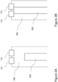
- Figures 2A and 2B show an embodiment in which the first sensing device 120 includes a first mechanical switching device 121, and the second sensing device 130 includes a second mechanical switching device 131.
- One or both of the mechanical switching devices 121, 131 may be a microswitch.
- the mechanical switching devices 121, 131 are disposed within a recess 180 of the housing of the alarm call point 100. In the present example, the mechanical switching devices 121, 131 are disposed at the end of the recess 180 furthest from the opening of the recess 180.
- Each of the mechanical switching devices 121, 131 can be actuated by a test key.
- the first mechanical switching device 121 and the second mechanical switching device 131 are disposed adjacent to one another so that a single test key 500 can actuate both switching devices 121,131, as shown in Figure 2B .
- the controller 110 outputs the test signal to the control panel 200. This arrangement allows a technician to test the alarm call point 100 while preventing subsequent alarm actions from being triggered by the control panel 200, using a single test key.
- Figures 3A and 3B show an embodiment in which the first sensing device 120 includes a first mechanical switching device 121, and the second sensing device 130 includes an optical switching device.
- the optical switching device includes a light source 133 configured to emit light (e.g. a beam of light), and a photodetector 134 configured to detect light emitted by the light source 133.
- the light source 133 may be configured to emit any suitable wavelength of light, e.g. ultraviolet, visible or infrared light.
- the light source 133 is configured to emit a beam of visible light.
- the light source 133 may be configured to emit a beam of infrared light.
- the mechanical switching device 121 and the optical switching device are disposed within a recess 180 of the housing of the alarm call point 100.
- the mechanical switching device 121 is disposed at the end of the recess 180 furthest from the opening of the recess 180.
- the light source 133 and the photodetector 134 are disposed so as to face each other.
- the light source 133 and the photodetector 134 are disposed on opposite sides of the recess 180.
- a light beam B emitted by the light source 133 can be detected by the photodetector 134.
- the second sensing device 130 outputs a signal to the controller 110 indicating that the test key has been inserted into the recess 180, and that the alarm call point 100 is in a test mode.
- the key 500 Upon fully inserting the key 500 into the recess 180, the key 500 actuates the first mechanical switching device 121. The controller 110 then outputs the test signal to the control panel 200. This arrangement allows a technician to test the alarm call point 100 while preventing subsequent alarm actions from being triggered by the control panel 200, using a single test key.
- FIG. 4 shows an embodiment in which the second sensing device 130 includes a wireless communication device 135.
- the wireless communication device 135 is configured to receive an identifier.
- the wireless communication device 135 is a radio-frequency identification (RFID) tag reader configured to receive the identifier from an RFID tag 600.
- RFID tag reader Upon receiving an identifier, the RFID tag reader outputs the identifier to the controller 110.
- RFID radio-frequency identification
- the controller 110 receives the identifier and determines whether the identifier corresponds to an identifier of an authorized user of the alarm call point 100. If the controller 110 receives the output from the first sensing device 120 and additionally determines that the identifier corresponds to an identifier of an authorized user of the alarm call point 100, the controller 110 outputs the test signal to the control panel 200. This arrangement provides enhanced security, as means of identification is required for a technician to perform the test.
- the second sensing device 130 may include a Hall effect switch which is triggered by a magnet on a test key to cause the second sensing device 130 to provide the output to the controller 110.
Landscapes
- Engineering & Computer Science (AREA)
- Physics & Mathematics (AREA)
- General Physics & Mathematics (AREA)
- Computer Security & Cryptography (AREA)
- Health & Medical Sciences (AREA)
- Toxicology (AREA)
- Electromagnetism (AREA)
- General Health & Medical Sciences (AREA)
- Artificial Intelligence (AREA)
- Computer Vision & Pattern Recognition (AREA)
- Computer Networks & Wireless Communication (AREA)
- Theoretical Computer Science (AREA)
- Business, Economics & Management (AREA)
- Emergency Management (AREA)
- Alarm Systems (AREA)
Abstract
Description
- The present invention relates to an alarm call point. The present invention also relates to an alarm system including an alarm call point and an external device, such as a control panel.
- Alarm call points or pull stations typically have a feature which allows them to be tested by a technician using a 'test key' without actually breaking the glass or the device which would normally be pressed or actuated in the event of a real alarm activation. When a test of an alarm call point is to be performed, a control panel that is connected to the alarm call point is put into a special test mode. Once in this mode, the control panel will not trigger any alarm actions (e.g. activating a sounder) if it receives an alarm signal from the call point being tested.
- The present invention provides an alarm call point which is able to discriminate between activation in an alarm situation and activation in a test situation (e.g. activation using a test key). This arrangement allows an alarm system to be tested without needing to put the control panel into a special test mode, making it easier and quicker to install, commission and test the system.
- According to an aspect of the present invention, there is provided an alarm call point comprising: a controller; a first sensing device configured to provide a first output to the controller in response to sensing a first input, the first output indicating an alarm condition; and a second sensing device configured to provide a second output to the controller in response to sensing a second input, the second output indicating that the alarm call point is in a test mode. The controller is configured to, in response to receiving the first output and the second output, output a test signal to an external device.
- The second sensing device may comprise a second mechanical switching device. The second sensing device may be configured to provide the second output in response to the second mechanical switching device being actuated by a key.
- The first sensing device may comprise a first mechanical switching device. The first sensing device may be configured to provide the first output in response to the first mechanical switching device being actuated by a key. The first mechanical switching device and the second mechanical switching device may be arranged so that they can be actuated by the same key in use.
- The second sensing device may comprise an optical switching device. The second sensing device may be configured to provide the second output in response to sensing the insertion of a key into a recess in the alarm call point.
- The first sensing device may comprise a first mechanical switching device. The first sensing device and the second sensing device may be arranged within the recess such that when the first mechanical switching device is actuated by a key in use, the optical switching device senses the insertion of the same key.
- The second sensing device may comprise a wireless communication device configured to receive an identifier. The second sensing device may be configured to provide the second output in response to receiving an identifier associated with a user, the second output including the identifier. The controller may be configured to receive the second output including the identifier and, in response to determining that the identifier corresponds to an identifier of an authorized user, output the test signal.
- The wireless communication device may comprise a radio-frequency identification (RFID) tag reader configured to receive the identifier from an RFID tag.
- The first sensing device may comprise a first mechanical switching device arranged to be actuated by a key.
- According to another aspect of the present invention, there is provided an alarm system comprising: an alarm call point as set out above; and an external device. The external device is configured to receive the test signal from the alarm call point.
- The external device may comprise a control panel.
- The control panel may comprise a controller configured to, in response to receiving the test signal from the alarm call point, send an acknowledgment signal to the alarm call point. The controller of the alarm call point may be configured to, in response to receiving the acknowledgment signal from the control panel, control an output device of the alarm call point to provide an output indicating that the acknowledgment signal has been received.
- The controller of the control panel may be configured to, in response to receiving the test signal from the alarm call point, send an acknowledgment signal to a cloud processing system.
- The external device may comprise a mobile electronic device.
- The present disclosure will now be described by way of example only with reference to the accompanying drawings in which:
-
Figure 1 is a block diagram showing a system including an alarm call point and a control panel; -
Figures 2A and 2B are schematic diagrams showing a sensing device according to an embodiment; -
Figures 3A and 3B are schematic diagrams showing a sensing device according to an embodiment; and -
Figure 4 is a schematic diagram showing a control panel including a sensing device according to an embodiment. -
Figure 1 shows an example of an alarm system including analarm call point 100 and anexternal device 200. In the present example, theexternal device 200 is a control panel. In other examples, the external device may be a mobile device, such as a mobile telephone. - The
alarm call point 100 includes acontroller 110 which is configured to control the overall operation of thealarm call point 100. In particular, thecontroller 110 is configured to generate an alarm signal indicating that an alarm condition is present and send this alarm signal to thecontrol panel 200 via acommunication device 150. In the present example, thecontroller 110 includes a processor which is configured to execute computer-readable instructions to implement the functionality described herein. However, in other examples, the controller may be implemented using hardware. - The
alarm call point 100 also includes afirst sensing device 120 and asecond sensing device 130. Thefirst sensing device 120 is configured to provide a first output to thecontroller 110 in response to sensing a first input. The first output indicates that an alarm condition is present. Thesecond sensing device 130 is configured to provide a second output to thecontroller 110 in response to sensing a second input. The second output indicates that thealarm call point 100 is in a test mode. When thecontroller 110 receives the first output only, the controller outputs an alarm signal to thecontrol panel 200. However, when thecontroller 110 receives both the first output and the second output, thecontroller 110 outputs a test signal to thecontrol panel 200. This indicates to thecontrol panel 200 that the alarm call point is being tested and is working correctly. - The
alarm call point 100 includes a housing (not shown) which covers and protects components of thealarm call point 100, such as thecontroller 110. The housing may include a recess into which a test key can be inserted to trigger the first sensing device 120 (and in some cases, the second sensing device 130) to provide an output. - In the present example, the
alarm call point 100 includes anoutput device 140. The output device may be, for example, a light output device (e.g. a light-emitting diode) or a sound output device such as a speaker. In other examples, theoutput device 150 may be omitted. - The
control panel 200 includes acontroller 210 and acommunication device 250 which allows thecontroller 210 to communicate with thealarm call point 100. When thecontroller 210 receives a test signal from thealarm call point 100, thecontroller 210 may respond by sending an acknowledgment signal to thealarm call point 100 via thecommunication device 250. In the present example, when thecontroller 110 of thealarm call point 100 receives the acknowledgment signal from thecontrol panel 200, it can control theoutput device 140 to provide an output indicating that the acknowledgment signal has been received. For example, if theoutput device 140 is a light output device, thecontroller 110 may control the light output device to illuminate when the acknowledgment signal has been received. This provides a technician with an indication that the communication between thealarm call point 100 and thecontrol panel 200 is working correctly. - Alternatively, or in addition, the
controller 210 may send an acknowledgment signal to a cloud processing system (not shown) when it receives the test signal from thealarm call point 100. Based on this signal, the cloud processing system may record the fact that communication between thealarm call point 100 and thecontrol panel 200 is working correctly. -
Figures 2A and 2B show an embodiment in which thefirst sensing device 120 includes a firstmechanical switching device 121, and thesecond sensing device 130 includes a secondmechanical switching device 131. One or both of themechanical switching devices mechanical switching devices recess 180 of the housing of thealarm call point 100. In the present example, themechanical switching devices recess 180 furthest from the opening of therecess 180. - Each of the
mechanical switching devices mechanical switching device 121 and the secondmechanical switching device 131 are disposed adjacent to one another so that asingle test key 500 can actuate both switching devices 121,131, as shown inFigure 2B . When both switching devices 121,131 are actuated, thecontroller 110 outputs the test signal to thecontrol panel 200. This arrangement allows a technician to test thealarm call point 100 while preventing subsequent alarm actions from being triggered by thecontrol panel 200, using a single test key. -
Figures 3A and 3B show an embodiment in which thefirst sensing device 120 includes a firstmechanical switching device 121, and thesecond sensing device 130 includes an optical switching device. The optical switching device includes alight source 133 configured to emit light (e.g. a beam of light), and aphotodetector 134 configured to detect light emitted by thelight source 133. Thelight source 133 may be configured to emit any suitable wavelength of light, e.g. ultraviolet, visible or infrared light. In the present example, thelight source 133 is configured to emit a beam of visible light. In other examples, thelight source 133 may be configured to emit a beam of infrared light. - The
mechanical switching device 121 and the optical switching device are disposed within arecess 180 of the housing of thealarm call point 100. In the present example, themechanical switching device 121 is disposed at the end of therecess 180 furthest from the opening of therecess 180. - The
light source 133 and thephotodetector 134 are disposed so as to face each other. In the present example, thelight source 133 and thephotodetector 134 are disposed on opposite sides of therecess 180. A light beam B emitted by thelight source 133 can be detected by thephotodetector 134. When atest key 500 is inserted into therecess 180 it passes between thelight source 133 and thephotodetector 134, blocking the light beam from thelight source 133 and preventing the light from reaching thephotodetector 134. In response, thesecond sensing device 130 outputs a signal to thecontroller 110 indicating that the test key has been inserted into therecess 180, and that thealarm call point 100 is in a test mode. Upon fully inserting the key 500 into therecess 180, the key 500 actuates the firstmechanical switching device 121. Thecontroller 110 then outputs the test signal to thecontrol panel 200. This arrangement allows a technician to test thealarm call point 100 while preventing subsequent alarm actions from being triggered by thecontrol panel 200, using a single test key. -
Figure 4 shows an embodiment in which thesecond sensing device 130 includes awireless communication device 135. Thewireless communication device 135 is configured to receive an identifier. In the present example, thewireless communication device 135 is a radio-frequency identification (RFID) tag reader configured to receive the identifier from anRFID tag 600. Upon receiving an identifier, the RFID tag reader outputs the identifier to thecontroller 110. - The
controller 110 receives the identifier and determines whether the identifier corresponds to an identifier of an authorized user of thealarm call point 100. If thecontroller 110 receives the output from thefirst sensing device 120 and additionally determines that the identifier corresponds to an identifier of an authorized user of thealarm call point 100, thecontroller 110 outputs the test signal to thecontrol panel 200. This arrangement provides enhanced security, as means of identification is required for a technician to perform the test. - Although various examples of the
second sensing device 130 have been described, the invention is not limited to these examples, and other types of sensing device may be used. For example, thesecond sensing device 130 may include a Hall effect switch which is triggered by a magnet on a test key to cause thesecond sensing device 130 to provide the output to thecontroller 110. - Various further modifications to the above described examples, whether by way of addition, deletion or substitution, will be apparent to the skilled person to provide additional examples, any and all of which are intended to be encompassed by the appended claims.
Claims (13)
- An alarm call point comprising:a controller;a first sensing device configured to provide a first output to the controller in response to sensing a first input, the first output indicating an alarm condition; anda second sensing device configured to provide a second output to the controller in response to sensing a second input, the second output indicating that the alarm call point is in a test mode;wherein the controller is configured to, in response to receiving the first output and the second output, output a test signal to an external device.
- An alarm call point according to claim 1, wherein the second sensing device comprises a second mechanical switching device, wherein the second sensing device is configured to provide the second output in response to the second mechanical switching device being actuated by a key.
- An alarm call point according to claim 2, wherein the first sensing device comprises a first mechanical switching device, wherein the first sensing device is configured to provide the first output in response to the first mechanical switching device being actuated by a key, and wherein the first mechanical switching device and the second mechanical switching device are arranged so that they can be actuated by the same key in use.
- An alarm call point according to claim 1, wherein the second sensing device comprises an optical switching device, wherein the second sensing device is configured to provide the second output in response to sensing the insertion of a key into a recess in the alarm call point.
- An alarm call point according to claim 4, wherein the first sensing device comprises a first mechanical switching device, wherein the first sensing device and the second sensing device are arranged within the recess such that when the first mechanical switching device is actuated by a key in use, the optical switching device senses the insertion of the same key.
- An alarm call point according to claim 1, wherein the second sensing device comprises a wireless communication device configured to receive an identifier, wherein the second sensing device is configured to provide the second output in response to receiving an identifier associated with a user, the second output including the identifier, and
wherein the controller is configured to receive the second output including the identifier and, in response to determining that the identifier corresponds to an identifier of an authorized user, output the test signal. - An alarm call point according to claim 6, wherein the wireless communication device comprises a radio-frequency identification (RFID) tag reader configured to receive the identifier from an RFID tag.
- An alarm call point according to claim 1, wherein the first sensing device comprises a first mechanical switching device arranged to be actuated by a key.
- An alarm system comprising:an alarm call point according to any one of the preceding claims; andan external device,wherein the external device is configured to receive the test signal from the alarm call point.
- An alarm system according to claim 9, wherein the external device comprises a control panel.
- An alarm system according to claim 10,wherein the control panel comprises a controller configured to, in response to receiving the test signal from the alarm call point, send an acknowledgment signal to the alarm call point, andwherein the controller of the alarm call point is configured to, in response to receiving the acknowledgment signal from the control panel, control an output device of the alarm call point to provide an output indicating that the acknowledgment signal has been received.
- An alarm system according to claim 10 or 11, wherein the controller of the control panel is configured to, in response to receiving the test signal from the alarm call point, send an acknowledgment signal to a cloud processing system.
- An alarm system according to claim 9, wherein the external device comprises a mobile electronic device.
Priority Applications (3)
| Application Number | Priority Date | Filing Date | Title |
|---|---|---|---|
| EP23160598.1A EP4428840B1 (en) | 2023-03-07 | 2023-03-07 | ALARM CALL CENTER |
| AU2024201490A AU2024201490A1 (en) | 2023-03-07 | 2024-03-06 | Alarm call point |
| US18/599,069 US12640030B2 (en) | 2023-03-07 | 2024-03-07 | Alarm call point |
Applications Claiming Priority (1)
| Application Number | Priority Date | Filing Date | Title |
|---|---|---|---|
| EP23160598.1A EP4428840B1 (en) | 2023-03-07 | 2023-03-07 | ALARM CALL CENTER |
Publications (2)
| Publication Number | Publication Date |
|---|---|
| EP4428840A1 true EP4428840A1 (en) | 2024-09-11 |
| EP4428840B1 EP4428840B1 (en) | 2026-05-20 |
Family
ID=85510997
Family Applications (1)
| Application Number | Title | Priority Date | Filing Date |
|---|---|---|---|
| EP23160598.1A Active EP4428840B1 (en) | 2023-03-07 | 2023-03-07 | ALARM CALL CENTER |
Country Status (3)
| Country | Link |
|---|---|
| US (1) | US12640030B2 (en) |
| EP (1) | EP4428840B1 (en) |
| AU (1) | AU2024201490A1 (en) |
Citations (3)
| Publication number | Priority date | Publication date | Assignee | Title |
|---|---|---|---|---|
| GB2289968A (en) * | 1994-05-31 | 1995-12-06 | Zettler Gmbh | Alarm with test function |
| DE102007020282A1 (en) * | 2007-04-30 | 2008-11-06 | Robert Bosch Gmbh | Signaling device with test mechanism and special key for actuating the test mechanism |
| GB2513733A (en) * | 2013-05-01 | 2014-11-05 | Ramtech Electronics Ltd | Emergency system |
Family Cites Families (41)
| Publication number | Priority date | Publication date | Assignee | Title |
|---|---|---|---|---|
| US3562730A (en) | 1968-04-29 | 1971-02-09 | American District Telegraph Co | Alarm control unit and test circuit therefor |
| US4412211A (en) | 1981-08-28 | 1983-10-25 | American District Telegraph Co. | System for test sequence annunciation |
| US4725818A (en) | 1985-09-13 | 1988-02-16 | Simplex Time Recorder Co. | Walk through test system |
| US4803467A (en) * | 1988-02-23 | 1989-02-07 | George Peters | Magnetic key lock provided with an alarm system |
| CA2200994C (en) | 1997-03-25 | 2001-07-31 | Digital Security Controls Ltd. | Walk-test control circuit for security alarm device |
| CA2258817C (en) | 1999-01-05 | 2003-08-05 | Digital Security Controls Ltd. | Dual mode panel |
| US6737967B2 (en) | 2002-05-10 | 2004-05-18 | Simplexgrinnell, Lp | Wireless walk through test system |
| US7042349B2 (en) | 2002-08-30 | 2006-05-09 | General Electric Company | Testing and installing sensors in a security system |
| CA2427320C (en) | 2003-04-30 | 2009-07-21 | Digital Security Controls Ltd. | Smoke detector with performance reporting |
| US7710256B2 (en) | 2006-02-23 | 2010-05-04 | Honeywell International Inc. | Method and apparatus for audio assisted testing |
| US10354516B2 (en) | 2006-09-15 | 2019-07-16 | Tyco Safety Products Canada, Ltd. | Method and apparatus for automated activation of a security system |
| US7786854B2 (en) | 2008-01-17 | 2010-08-31 | Honeywell International Inc. | Alarm system walk test |
| US7956740B2 (en) | 2008-08-18 | 2011-06-07 | Tyco Safety Products Canada Ltd. | Alarm system configuration validation |
| DE102010031910A1 (en) | 2010-07-22 | 2012-01-26 | Fraunhofer-Gesellschaft zur Förderung der angewandten Forschung e.V. | Method for determining the level of a rail or track-bound logistics system |
| GB2506679A (en) | 2012-10-08 | 2014-04-09 | Thorn Security | Distributed fire detection system interface that controls data routing between sub-systems |
| ES2458940B1 (en) | 2012-11-05 | 2014-10-29 | Orona, S. Coop. | Method and installation of remote alarm system check in elevators |
| US9257032B2 (en) | 2013-02-27 | 2016-02-09 | Total Walther Gmbh, Feuerschutz Und Sicherheit | System and method for emergency communication in a TCP/IP based redundant fire panel network |
| US8994525B2 (en) | 2013-03-15 | 2015-03-31 | Tyco Fire & Security Gmbh | Method for testing notification appliances in alarm systems |
| US9030314B2 (en) | 2013-03-15 | 2015-05-12 | Tyco Fire & Security Gmbh | Method for inspecting and testing notification appliances in alarm systems |
| US9390616B2 (en) | 2013-10-03 | 2016-07-12 | Tyco Safety Products Canada Ltd. | Method and apparatus for determining maintenance needs and validating the installation of an alarm system |
| GB2520757A (en) | 2013-11-29 | 2015-06-03 | Thorn Security | Control panel for a fire detection system |
| US9552720B2 (en) | 2014-01-17 | 2017-01-24 | Tyco Fire & Security Gmbh | Testing system and method for fire alarm system |
| US9767679B2 (en) | 2014-02-28 | 2017-09-19 | Tyco Fire & Security Gmbh | Method and apparatus for testing fire alarm initiating devices |
| CN106325256A (en) | 2015-06-15 | 2017-01-11 | 泰科电子(上海)有限公司 | Detection method of household electrical appliance bus control system |
| US10008105B2 (en) | 2015-09-30 | 2018-06-26 | Tyco Fire & Security Gmbh | System and method for charging supplemental power units for alarm notification devices |
| US10400475B2 (en) * | 2015-12-01 | 2019-09-03 | Schlage Lock Company Llc | Systems and methods for key recognition |
| US10558917B2 (en) | 2017-04-20 | 2020-02-11 | Tyco Fire & Security Gmbh | Artificial intelligence and natural language processing based building and fire systems management system |
| EP3619696A1 (en) | 2017-05-01 | 2020-03-11 | Johnson Controls Fire Protection LP | Fire alarm building management integration |
| US20180365973A1 (en) | 2017-06-14 | 2018-12-20 | Honeywell International Inc. | Systems and methods for testing a security system |
| EP3746998B1 (en) * | 2018-02-02 | 2023-09-20 | Siemens Schweiz AG | Safety device inspection |
| ES2912546T3 (en) | 2018-05-11 | 2022-05-26 | Carrier Corp | System and method for testing network alarm units |
| US11749095B2 (en) | 2019-02-05 | 2023-09-05 | Johnson Controls Fire Protection LP | Fire alarm peripheral addressing using a unique identifier |
| US12482868B2 (en) | 2019-03-06 | 2025-11-25 | Tyco Fire & Security Gmbh | Lithium battery passivation detection, activation and maintenance module |
| CN111537871B (en) | 2020-04-10 | 2022-10-18 | Oppo(重庆)智能科技有限公司 | Key testing method and device, electronic equipment and storage medium |
| JP7470918B2 (en) * | 2020-04-24 | 2024-04-19 | パナソニックIpマネジメント株式会社 | Safety switches and switch systems |
| US12154426B2 (en) * | 2020-07-03 | 2024-11-26 | Siemens Schweiz Ag | Method for automatic testing of a fire alarm system |
| CN112286093A (en) | 2020-10-14 | 2021-01-29 | 广州博冠智能科技有限公司 | Remote control test method, device, equipment and storage medium of remote controller |
| US20240312333A1 (en) * | 2021-07-19 | 2024-09-19 | Rudders RLS Pty Ltd | Sensing system |
| MX2024008857A (en) | 2022-01-25 | 2024-07-25 | Communications Test Design Inc | Systems, apparatus and methods for automatically testing security alarm devices. |
| US12518615B2 (en) | 2023-12-29 | 2026-01-06 | Tyco Fire & Security Gmbh | Control panel managed testing of alarm initiating devices |
| DE102024120119A1 (en) | 2024-07-15 | 2025-06-18 | Schaeffler Technologies AG & Co. KG | Computer-implemented method for providing machine element data, and computer network |
-
2023
- 2023-03-07 EP EP23160598.1A patent/EP4428840B1/en active Active
-
2024
- 2024-03-06 AU AU2024201490A patent/AU2024201490A1/en active Pending
- 2024-03-07 US US18/599,069 patent/US12640030B2/en active Active
Patent Citations (3)
| Publication number | Priority date | Publication date | Assignee | Title |
|---|---|---|---|---|
| GB2289968A (en) * | 1994-05-31 | 1995-12-06 | Zettler Gmbh | Alarm with test function |
| DE102007020282A1 (en) * | 2007-04-30 | 2008-11-06 | Robert Bosch Gmbh | Signaling device with test mechanism and special key for actuating the test mechanism |
| GB2513733A (en) * | 2013-05-01 | 2014-11-05 | Ramtech Electronics Ltd | Emergency system |
Also Published As
| Publication number | Publication date |
|---|---|
| EP4428840B1 (en) | 2026-05-20 |
| US12640030B2 (en) | 2026-05-26 |
| US20240304079A1 (en) | 2024-09-12 |
| AU2024201490A1 (en) | 2024-09-26 |
Similar Documents
| Publication | Publication Date | Title |
|---|---|---|
| US20120032812A1 (en) | Multiple optical axis photoelectric sensor | |
| JP5114109B2 (en) | RFID tag program control | |
| JP2967056B2 (en) | Gaming machine fraud monitoring device | |
| US9361773B2 (en) | Door/window contact system | |
| US9905102B2 (en) | Open scattered light smoke detector and testing device for an open scattered light smoke detector of this type | |
| EP3113137A1 (en) | Security sensor | |
| US20240304079A1 (en) | Alarm call point | |
| KR20100130844A (en) | Automatic door access control system | |
| GB2289968A (en) | Alarm with test function | |
| KR20210026128A (en) | FIRE HYDRANT BASED IoT FIRE ALARM SYSTEM | |
| CN104240410A (en) | Pos system and method for operating a pos system | |
| CA2344840A1 (en) | Device with built-in signal discrimination and output synchronization circuits | |
| CN102419188B (en) | Operating panel for a measuring device | |
| KR20030078410A (en) | System and method for crime prevention and disaster prevention using short message service | |
| KR101022368B1 (en) | Security system and method | |
| JP4149844B2 (en) | Electronic device with optical communication function, control method thereof, control program thereof, and optical communication device | |
| US12424076B2 (en) | Enhanced visual and audio device for use in access control systems | |
| AU2013101112A4 (en) | Anti-skimming device for automated teller machine | |
| JP6899007B2 (en) | Entry / exit management system | |
| JP6652356B2 (en) | Access control system | |
| JP7640778B1 (en) | Security system and security method | |
| KR100226317B1 (en) | Automated guided information transmitter-receiver | |
| JP2021092893A (en) | Monitoring device, monitoring program, and monitoring system | |
| CN214752034U (en) | Hand-held number calling machine | |
| JP3215514B2 (en) | Card type remote control switch |
Legal Events
| Date | Code | Title | Description |
|---|---|---|---|
| PUAI | Public reference made under article 153(3) epc to a published international application that has entered the european phase |
Free format text: ORIGINAL CODE: 0009012 |
|
| STAA | Information on the status of an ep patent application or granted ep patent |
Free format text: STATUS: REQUEST FOR EXAMINATION WAS MADE |
|
| 17P | Request for examination filed |
Effective date: 20230310 |
|
| AK | Designated contracting states |
Kind code of ref document: A1 Designated state(s): AL AT BE BG CH CY CZ DE DK EE ES FI FR GB GR HR HU IE IS IT LI LT LU LV MC ME MK MT NL NO PL PT RO RS SE SI SK SM TR |
|
| GRAP | Despatch of communication of intention to grant a patent |
Free format text: ORIGINAL CODE: EPIDOSNIGR1 |
|
| STAA | Information on the status of an ep patent application or granted ep patent |
Free format text: STATUS: GRANT OF PATENT IS INTENDED |
|
| INTG | Intention to grant announced |
Effective date: 20250711 |
|
| GRAJ | Information related to disapproval of communication of intention to grant by the applicant or resumption of examination proceedings by the epo deleted |
Free format text: ORIGINAL CODE: EPIDOSDIGR1 |
|
| STAA | Information on the status of an ep patent application or granted ep patent |
Free format text: STATUS: REQUEST FOR EXAMINATION WAS MADE |
|
| INTC | Intention to grant announced (deleted) | ||
| GRAP | Despatch of communication of intention to grant a patent |
Free format text: ORIGINAL CODE: EPIDOSNIGR1 |
|
| STAA | Information on the status of an ep patent application or granted ep patent |
Free format text: STATUS: GRANT OF PATENT IS INTENDED |
|
| INTG | Intention to grant announced |
Effective date: 20251209 |
|
| GRAS | Grant fee paid |
Free format text: ORIGINAL CODE: EPIDOSNIGR3 |
|
| GRAA | (expected) grant |
Free format text: ORIGINAL CODE: 0009210 |
|
| STAA | Information on the status of an ep patent application or granted ep patent |
Free format text: STATUS: THE PATENT HAS BEEN GRANTED |
|
| P01 | Opt-out of the competence of the unified patent court (upc) registered |
Free format text: CASE NUMBER: UPC_APP_0011260_4428840/2026 Effective date: 20260330 |
|
| AK | Designated contracting states |
Kind code of ref document: B1 Designated state(s): AL AT BE BG CH CY CZ DE DK EE ES FI FR GB GR HR HU IE IS IT LI LT LU LV MC ME MK MT NL NO PL PT RO RS SE SI SK SM TR |
|
| REG | Reference to a national code |
Ref country code: CH Ref legal event code: F10 Free format text: ST27 STATUS EVENT CODE: U-0-0-F10-F00 (AS PROVIDED BY THE NATIONAL OFFICE) Effective date: 20260520 Ref country code: GB Ref legal event code: FG4D |
|
| REG | Reference to a national code |
Ref country code: DE Ref legal event code: R096 Ref document number: 602023017370 Country of ref document: DE |