EP4428822A1 - Map optimization method and apparatus, and electronic device and storage medium - Google Patents
Map optimization method and apparatus, and electronic device and storage medium Download PDFInfo
- Publication number
- EP4428822A1 EP4428822A1 EP22885799.1A EP22885799A EP4428822A1 EP 4428822 A1 EP4428822 A1 EP 4428822A1 EP 22885799 A EP22885799 A EP 22885799A EP 4428822 A1 EP4428822 A1 EP 4428822A1
- Authority
- EP
- European Patent Office
- Prior art keywords
- zone
- explore
- map
- optimized
- obstacle
- Prior art date
- Legal status (The legal status is an assumption and is not a legal conclusion. Google has not performed a legal analysis and makes no representation as to the accuracy of the status listed.)
- Pending
Links
Images


Classifications
-
- G—PHYSICS
- G05—CONTROLLING; REGULATING
- G05D—SYSTEMS FOR CONTROLLING OR REGULATING NON-ELECTRIC VARIABLES
- G05D1/00—Control of position, course, altitude or attitude of land, water, air or space vehicles, e.g. using automatic pilots
- G05D1/02—Control of position or course in two dimensions
- G05D1/021—Control of position or course in two dimensions specially adapted to land vehicles
- G05D1/0231—Control of position or course in two dimensions specially adapted to land vehicles using optical position detecting means
- G05D1/0246—Control of position or course in two dimensions specially adapted to land vehicles using optical position detecting means using a video camera in combination with image processing means
-
- G—PHYSICS
- G06—COMPUTING OR CALCULATING; COUNTING
- G06T—IMAGE DATA PROCESSING OR GENERATION, IN GENERAL
- G06T11/00—Two-dimensional [2D] image generation
- G06T11/20—Drawing from basic elements
-
- G—PHYSICS
- G01—MEASURING; TESTING
- G01C—MEASURING DISTANCES, LEVELS OR BEARINGS; SURVEYING; NAVIGATION; GYROSCOPIC INSTRUMENTS; PHOTOGRAMMETRY OR VIDEOGRAMMETRY
- G01C21/00—Navigation; Navigational instruments not provided for in groups G01C1/00 - G01C19/00
- G01C21/38—Electronic maps specially adapted for navigation; Updating thereof
- G01C21/3804—Creation or updating of map data
- G01C21/3807—Creation or updating of map data characterised by the type of data
- G01C21/383—Indoor data
-
- G—PHYSICS
- G01—MEASURING; TESTING
- G01C—MEASURING DISTANCES, LEVELS OR BEARINGS; SURVEYING; NAVIGATION; GYROSCOPIC INSTRUMENTS; PHOTOGRAMMETRY OR VIDEOGRAMMETRY
- G01C21/00—Navigation; Navigational instruments not provided for in groups G01C1/00 - G01C19/00
- G01C21/38—Electronic maps specially adapted for navigation; Updating thereof
- G01C21/3804—Creation or updating of map data
- G01C21/3833—Creation or updating of map data characterised by the source of data
- G01C21/3848—Data obtained from both position sensors and additional sensors
-
- G—PHYSICS
- G01—MEASURING; TESTING
- G01C—MEASURING DISTANCES, LEVELS OR BEARINGS; SURVEYING; NAVIGATION; GYROSCOPIC INSTRUMENTS; PHOTOGRAMMETRY OR VIDEOGRAMMETRY
- G01C21/00—Navigation; Navigational instruments not provided for in groups G01C1/00 - G01C19/00
- G01C21/38—Electronic maps specially adapted for navigation; Updating thereof
- G01C21/3863—Structures of map data
- G01C21/3867—Geometry of map features, e.g. shape points, polygons or for simplified maps
-
- G—PHYSICS
- G05—CONTROLLING; REGULATING
- G05D—SYSTEMS FOR CONTROLLING OR REGULATING NON-ELECTRIC VARIABLES
- G05D1/00—Control of position, course, altitude or attitude of land, water, air or space vehicles, e.g. using automatic pilots
- G05D1/02—Control of position or course in two dimensions
- G05D1/021—Control of position or course in two dimensions specially adapted to land vehicles
- G05D1/0268—Control of position or course in two dimensions specially adapted to land vehicles using internal positioning means
- G05D1/0274—Control of position or course in two dimensions specially adapted to land vehicles using internal positioning means using mapping information stored in a memory device
-
- G—PHYSICS
- G06—COMPUTING OR CALCULATING; COUNTING
- G06T—IMAGE DATA PROCESSING OR GENERATION, IN GENERAL
- G06T11/00—Two-dimensional [2D] image generation
- G06T11/60—Creating or editing images; Combining images with text
- G06T11/65—Creating or editing images; Combining images with text on geographic maps
-
- A—HUMAN NECESSITIES
- A47—FURNITURE; DOMESTIC ARTICLES OR APPLIANCES; COFFEE MILLS; SPICE MILLS; SUCTION CLEANERS IN GENERAL
- A47L—DOMESTIC WASHING OR CLEANING; SUCTION CLEANERS IN GENERAL
- A47L2201/00—Robotic cleaning machines, i.e. with automatic control of the travelling movement or the cleaning operation
- A47L2201/04—Automatic control of the travelling movement; Automatic obstacle detection
Definitions
- the present disclosure relates to data processing technologies, and in particular, to a map optimization method, an apparatus, an electronic device and a storage medium.
- An autonomous mobile device refers to a smart device configured to autonomously execute predetermined tasks within a predetermined work zone.
- autonomous mobile devices typically include, but are not limited to, cleaning robots (e.g., smart floor sweeping robots, smart floor mopping robots, window cleaning robots), companion mobile robots (e.g., smart electronic pets, nanny robots), service type mobile robots (e.g., reception robots at restaurants, hotels, meeting places), industrial inspection smart devices (e.g., electric power inspection robots, smart forklifts, etc.), security robots (e.g., home or commercial use bodyguard robots), etc.
- cleaning robots e.g., smart floor sweeping robots, smart floor mopping robots, window cleaning robots
- companion mobile robots e.g., smart electronic pets, nanny robots
- service type mobile robots e.g., reception robots at restaurants, hotels, meeting places
- industrial inspection smart devices e.g., electric power inspection robots, smart forklifts, etc
- An autonomous mobile device typically moves autonomously within a limited space.
- a cleaning robot typically moves in an indoor space.
- a service type mobile robot typically moves within a special limited space such as a hotel, a meeting place, etc. This limited space may be referred to as a work zone of the autonomous mobile device.
- a work zone of an autonomous mobile device is not an open space, but may be divided into different zones, such as multiple rooms, by walls, doors or other obstacles.
- the autonomous mobile device moves in a target zone, it creates a map of the target zone. In subsequent operations, it may adjust a moving direction and route based on the created map.
- the autonomous mobile device In the process of the autonomous mobile device creating the map, due to influence of factors such as algorithm localization errors, level of accuracy of localization components, etc., localization data with errors may be generated, causing possible errors in the created map. For example, erroneous zones may appear, erroneous walls may appear, thicknesses of walls may not be consistent.
- the autonomous mobile device adjusts the moving direction and route based on the created map, being affected by the errors in the map, it may make erroneous adjustments, thereby reducing the operation efficiency of the autonomous mobile device.
- the present disclosure provides a map optimization method, an apparatus, an electronic device and a storage medium, to solve the above technical problems.
- the present disclosure provides a map optimization method, including:
- the method also includes: separating a wall zone from the obstacle zone, and optimizing the wall zone, to obtain an optimized map.
- determining and deleting an error zone from the explore zone in view of the covered zone and the obstacle zone includes:
- the method also includes:
- the obstacle zone also includes an ordinary obstacle zone
- optimizing the wall zone also includes: expanding, based on the new outer wall zone profile line, the explore zone in the third optimized map to the new outer wall zone profile line, to obtain an optimized explore zone, and to obtain an optimized map.
- expanding, based on the new outer wall zone profile line, the explore zone in the third optimized map to the new outer wall zone profile line, to obtain the optimized explore zone includes: with regard to a plurality of key points on the new outer wall zone profile line, searching in a predetermined direction toward an inside of the third optimized map based on these key points, and labelling non-explore zone points found in the search as new explore zone points, until points in the explore zone of the third optimized map are found, wherein the new explore zone points and the points in the explore zone of the third optimized map form an optimized explore zone.
- the present disclosure provides a map optimization apparatus, including:
- the apparatus also includes: a wall optimization module, configured to separate a wall zone from the obstacle zone, and to optimize the wall zone, to obtain an optimized map.
- a wall optimization module configured to separate a wall zone from the obstacle zone, and to optimize the wall zone, to obtain an optimized map.
- the error zone deleting module is specifically configured to:
- the error zone deleting module is also configured to:
- the obstacle zone also includes an ordinary obstacle zone
- the wall optimization module is specifically configured to:
- the wall optimization module is also specifically configured to: expand, based on the new outer wall zone profile line, the explore zone in the third optimized map to the new outer wall zone profile line, to obtain an optimized explore zone, and to obtain an optimized map.
- the wall optimization module when the wall optimization module is configured to expand, based on the new outer wall zone profile line, the explore zone in the third optimized map to the new outer wall zone profile line, to obtain the optimized explore zone, the wall optimization module is specifically configured to: with regard to a plurality of key points on the new outer wall zone profile line, search in a predetermined direction toward an inside of the third optimized map based on the key points, and label non-explore zone points found in the search as new explore zone points, until points in the explore zone of the third optimized map are found, wherein the new explore zone points and the points in the explore zone of the third optimized map form an optimized explore zone.
- the present disclosure provides an electronic device, including: a storage device, configured to store program instructions; a processor, configured to retrieve and execute the program instructions from the storage device, to perform the method according to the first aspect.
- the present disclosure provides a computer-readable storage medium.
- the storage medium stores a computer program.
- the computer program is executed by the processor, the method according to the first aspect is performed.
- the present disclosure provides a program product, including a computer program.
- the computer program is executed by the processor, the method according to the first aspect is performed.
- the present disclosure provides a map optimization method, an apparatus, an electronic device and a storage medium.
- the map optimization method includes: obtaining an original map, the original map including an explore zone, a covered zone, an obstacle zone; determining and deleting an error zone from the explore zone in view of the covered zone and the obstacle zone.
- an error zone is determined and deleted from the original map, thereby realizing the optimization of the original map, such that the optimized map is closer to the actual map. This enables the autonomous mobile device to execute tasks more efficiently based on the optimized map.
- an autonomous mobile device is equipped with various types of sensors configured to explore an inner space of a work zone, and based on sensor data, the autonomous mobile device can create a work zone map or adjust a moving direction and route, etc.
- Direct localization means that localization information of the autonomous mobile device is directly used as the points in the map.
- dead reckoning sensors sometimes in combination with cameras or light detection and ranging (Lidar) sensors
- Lidar light detection and ranging
- location coordinates (localization information) of the current location of the autonomous mobile device may be computed in real time through a Simultaneous Localization And Mapping (SLAM) algorithm.
- SLAM Simultaneous Localization And Mapping
- location coordinates when the autonomous mobile device touches an obstacle may be detected.
- the location coordinates may correspond to corresponding points in the map.
- Indirect localization means points in the map may be indirectly calculated based on the localization information of the autonomous mobile device and the work principle of a light detection and ranging (Lidar) sensor.
- an obstacle that forms a certain relative angle and has a certain distance with respect to the autonomous mobile device may be detected in a contactless manner.
- location coordinates of the detected obstacle may be indirectly calculated based on the location coordinates of the autonomous mobile device itself and the relative angle and distance of the detected obstacle with respect to the autonomous mobile device.
- the location coordinates of the detected obstacle may correspond to corresponding points in the map.
- the space For the space between the autonomous mobile device and the detected obstacle, because a detecting light of the light detection and ranging (Lidar) sensor passes through the space, the space also corresponds to corresponding points in the map. Certain errors may exist in these two localization methods, which may cause the ultimately created map to have some differences from the actual map, i.e., the created map may not be accurate. For example, surplus zones may exist in the created map, or the walls in the map may be irregular, etc. As such, when the created map is used as a basis for planning a moving route or for adjusting the moving direction, erroneous planning may occur, which may reduce the work efficiency of the autonomous mobile device.
- Lidar light detection and ranging
- Errors may exist in the original map of the autonomous mobile device due to errors in the localization performed through an algorithm or due to factors of a localization device itself.
- the map may have an erroneous zone or an erroneous wall, or the thicknesses of the walls may be different, the walls may be curved, etc.
- the technical issues to be addressed by the present disclosure primarily include:
- the present disclosure provides a map optimization method, an apparatus, an electronic device and a storage medium, to further optimize and adjust the created map, such that the optimized map is closer to the actual map, thereby avoiding map inaccuracy and low work efficiency caused by errors in the map.
- FIG. 1 is a schematic illustration of an application scene of the present disclosure.
- the autonomous mobile device is a cleaning robot 101, it may be configured to perform indoor cleaning tasks.
- the cleaning robot 101 may traverse the indoor space (i.e., cleaning the indoor floor) to create an original map of a work zone.
- the method of the present disclosure may be used to optimize the original map, to obtain an optimized map.
- the optimized map may be used as a basis for the route planning, and subsequent cleaning tasks may be performed.
- the specific optimization process can refer to the following various embodiments.
- FIG. 2 is a flowchart illustrating a map optimization method, according to an embodiment of the present disclosure.
- the method of this embodiment may include: S201, obtaining an original map, the original map including an explore zone, a covered zone, an obstacle zone (including a wall zone).
- the map optimization method may be executed after the autonomous mobile device has moved within the work zone and created the map of the work zone.
- the obtained original map refers to a map created during the movement of the autonomous mobile.
- all locations may be set as unexplored zones.
- the autonomous mobile device moves in the work zone. Whenever the autonomous mobile device arrives at a location point, the autonomous mobile device re-determines properties of this location point. Alternatively, based on a trajectory traversed by the autonomous mobile device within a time period, properties of each location point on the trajectory may be re-determined.
- properties of each location point may be one or more of unexplored, already explored, already covered, obstacle present, etc.
- an unexplored location point is a location point that has not been detected by the autonomous mobile device through direct localization or indirect localization.
- an already explored location point is a location point that has been previously detected by the autonomous mobile device through direct localization or indirect localization, such as a location that the autonomous mobile device actually reached, and a space that the detecting light of the light detection and ranging (Lidar) sensor of the autonomous mobile device can pass through, and locations of obstacles that can reflect the detecting light.
- Lidar light detection and ranging
- An already covered location point is a location point that has been detected through direct localization, which is also a location that the autonomous mobile device actually reached. From the above descriptions, it can be seen that an already covered location point may also be an already explored location point, but an already explored location point may not necessarily be an already covered location point.
- An obstacle present location point is a location point where an obstacle may be detected and recognized by the autonomous mobile device through direct localization or indirect localization, which typically includes a location point determined in view of signals obtained by components such as a collision sensor, a wheel drop sensor. To implement the map optimization method of the present disclosure, it may be needed to separate location points corresponding to walls from location points of the obstacles.
- location points of the walls are location points of walls that may be detected and recognized by the autonomous mobile device through direct localization or indirect localization. After the location points of the walls are separated from the obstacle present location points, the remaining location points are ordinary obstacle present location points.
- a wall is a type of a special obstacle. Wall present location points may be separated from the obstacle present location points based on information obtained from various sensors. For example, according to the above-described definitions of direct localization and indirect localization, it may be determined whether an obtained obstacle present location point is a wall present location point based on the information obtained through various sensors. Different values may be assigned to these two types of location points.
- a wall present location point may be assigned with 100, and a location point where an obstacle of other types exist may be assigned with 85, thereby differentiating the two types of location points.
- ordinary obstacle present location points and wall present location points may have already been separated and marked.
- wall present location points may be separated from obstacle present location points in the original map.
- the specific separating methods for separating the ordinary obstacle present location points and wall present location points are not issues to be addressed by the present disclosure, but are premises of the map optimization method of the present disclosure.
- Related separating methods may have various forms in the existing technology, some can refer to Chinese Patent Applications that are published as CN113064413A , CN111862133A .
- properties of each location point may be determined in view of various data generated in the map creation process.
- the autonomous mobile device may create the map of the target zone while moving in the target zone.
- the unexplored location points the already explored location points, the already covered location points, the obstacle present location points (including wall present location points and ordinary obstacle present location points) in the map
- these locations are displayed in the map using different pixel values.
- the pixel value for an unexplored location point may be 75
- the pixel value for an already explored location point may be 25
- the pixel value for an already covered location point may be
- the pixel value for an ordinary obstacle present location point may be 85
- the pixel value for a created wall present location point may be 100.
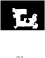
- the original map is shown in FIG. 5-1 .
- all location points in the map may be divided into a plurality of zones, at least including an explore zone, a covered zone, an obstacle zone (including a wall zone and/or an ordinary obstacle zone).
- the explore zone may be a zone formed by all already explored location points, and the explore zone may represent the maximum range the autonomous mobile device can detect (including zones that can be determined through direct localization and indirect localization).
- the covered zone may be a zone formed by all already covered location points, and the covered zone may represent a zone that the autonomous mobile device can actually reach.
- the obstacle zone may be a zone formed by all obstacle present location points, and the obstacle zone may be a zone that the autonomous mobile device cannot pass through, regardless of whether the autonomous mobile device has attempted to pass through this zone.
- the obstacle zone may be specifically divided into a wall zone and an ordinary obstacle zone.
- the wall zone may be a zone formed by all wall present location points.
- FIG. 5-2 schematically depicts the explore zone, the covered zone, the ordinary obstacle zone, the wall zone. It should be noted that because in the actual map, the shape and distribution of each zone are complex, FIG. 5-2 is only illustrative, and does not list all explore zones, covered zones, ordinary obstacle zones, wall zones. In addition, some selection boxes include not just one type of zone, but a mixture or overlap of multiple types of zones. The displayed zone is only the main zone type or representative zone type in the selection box. Thus, FIG. 5-2 does not intend to impose limitations on the above various types of zones.
- the map optimization method may be executed separately.
- the obtained original map may be the already created map.
- the created map (or referred to as a historical map) may be previously created by the autonomous mobile device and stored in the autonomous mobile device or in a server.
- the created map may also be a historical map created by another autonomous mobile device when operating in the same work zone and stored in the server. For example, if a home has a floor sweeping robot and a floor mopping robot, because the robots both perform cleaning of the floors of the rooms of the same home, the work zones of the two devices are the same.
- the floor sweeping robot may store a map of the rooms of the home created during its operation in a server. Although the floor mopping robot may not have been operated in this work zone itself, it can obtain the historical map of the work zone of the rooms of the home directly from the server.
- each location point and the name of each zone used in the present disclosure may use other definitions.
- the sources of data referred to by the names are deterministic.
- the explore zone may have the largest area, which would likely have an overlap with the covered zone, the obstacle zone.
- a wall zone in the obstacle zone is a boundary of the work zone.
- the covered zone exists inside the work zone that is surrounded by the wall zone(s). Because the explore zone includes location points detected or calculated through indirect localization by sensors of the autonomous mobile device, this zone most likely has an error zone caused by environmental influence, sensor errors, and/or calculation inaccuracy.
- a location point determined by a distance-measuring sensor such as a Lidar can easily be affected by the environment of the work zone.
- the Lidar would likely be affected by the mirror reflection, the refraction of the detecting light, which can cause errors in the distance measurement.
- the explore zone in the original map may be optimized.
- the map optimization method provided by the present disclosure includes: obtaining an original map, the original map including an explore zone, a covered zone, an obstacle zone (including at least a wall zone); determining and deleting an error zone from the explore zone in view of the covered zone, the obstacle zone.
- the error zone is determined and deleted from the original map, thereby accomplishing the optimization of the original map, such that it is closer to the actual map, which enables the autonomous mobile device to more efficiently execute tasks based on the optimized map.
- a wall zone may be separated from the obstacle zone, and the wall zone may be optimized, to obtain an optimized map.
- the wall in the original map becomes closer to the actual situation, and the map is further improved.
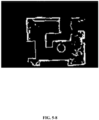
- the above-described determining and deleting the error zone from the explore zone in view of the covered zone, the obstacle zone may also include: extracting an outer profile of the explore zone as shown in FIG. 5-3 , to obtain an explore zone profile line as shown in FIG. 5-4 ; extracting an outer profile of the covered zone (as shown in FIG. 5-5 ), to obtain a covered zone profile line (the profile line formed at the border between the black and white portions as shown in FIG. 5-5 ); with respect to a plurality of key points on the covered zone profile line, expanding the covered zone outwardly based on these key points until the covered zone touches the obstacle zone and/or the explore zone, to obtain an expanded covered zone, as shown in FIG.
- the key points refer to points that have a key function in forming the profile of a certain zone or those adjacent such points; a plurality of key points means that, to form the profile of the above-described certain zone, at least a plurality of key points are needed to form the profile of the certain zone.
- the three vertex points / points adjacent to the vertex points of the triangular profile are key points, and a plurality of key points that can form the triangular profile include at least these three points;
- the four vertex points / points adjacent to the vertex points of the rectangle are key points, and a plurality of key points that can form the rectangular profile include at least these four points; for the profile having the shape shown in FIG. 8 , six vertex points A1, B1, C1, D1, E1, F1 or their adjacent points A2, B2, C2, D2, E2, F2 shown in FIG.
- a plurality of key points that can form this profile include at least six points: at least one point from A1 or A2, at least one point from B1 or B2, at least one point from C1 or C2, at least one point from D1 or D2, at least one point from E1 or E2, at least one point from F1 or F2.
- one or more pixels may be used as the width standard for the profile line.
- location points in the explore zone that are adjacent to the unexplored zone may be used to form the explore zone profile line (width is one pixel).
- the covered zone may be expanded.
- location points in the covered zone that are adjacent to other zones may be extracted to form the covered zone profile line (width is one pixel), and the covered zone may be expanded outwardly at least based on a plurality of key points on the covered zone profile line.
- the condition for stopping the expansion may be touching the profile line of the obstacle zone and/or the explore zone.
- expanding outwardly based on certain point means assigning one or more properties of this point to all location points on a segment that extends in a predetermine direction from this point as a starting point to a target point. This will be explained in detail with reference to the example shown in FIG. 3 .
- each lattice represents a pixel
- number "1" is used to indicate a location point in the covered zone (which may also be used to represent the property of "already covered")
- number "2" is used to indicate a location point in the wall zone (which may also be used to represent the property of "wall present”).
- Points on the covered zone profile line may be expanded in a predetermined horizontal direction.
- a result of the expansion based on one of the points on the covered zone profile line is shown in sub-figure "b" of FIG. 3 .
- the expansion shown here is only an example expansion method, which does not limit the specific expansion method to be used.
- the expansion of the covered zone based on the points on the covered zone profile line may be performed along a certain pre-set angle or multiple pre-set angles.
- the advantage of this type of expansion is, even when the wall zone is discontinuous and has break points, the expanded covered zone does not extend unlimitedly.
- Points in the covered zone are locations actually reached by the autonomous mobile device, and may not necessarily represent all of the space outside of the obstacle zone in the work zone.
- the expanded covered zone obtained through expansion are locations that actually can be reached by the autonomous mobile device determined based on the original map using an algorithm.
- searching toward an inside of the explore zone based on these key points may be performed.
- a zone between the explore zone profile line and the encountered obstacle zone may be determined as a first error zone; with respect to a plurality of key points on the explore zone profile line, searching toward an inside of the explore zone based on these key points may be performed.
- the searching process if the expanded covered zone is first encountered, a zone between the explore zone profile line and the encountered expanded covered zone does not belong to the expanded covered zone.
- the first error zone may be deleted from the explore zone, to obtain a first optimized map.
- first error zone used herein is only for the purpose of indicating an error zone having such properties, in order to distinguish from error zones determined using other conditions, and this term should not limit the present disclosure.
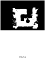
- the expanded covered zone may extend such that some error zones may overlap the expanded covered zone, which may not be deleted through the above steps. Therefore, the following steps may be further executed: deleting a zone corresponding to the obstacle zone from the explore zone in the first optimized map, to obtain a partitioned map, as shown in FIG. 5-9 ; a zone corresponding to the obstacle zone in the first optimized map is an obstacle zone map, as shown in FIG.
- the partitioned map includes a plurality of explore zone blocks; a second error zone may be determined from the plurality of explore zone blocks; the second error zone may have no overlap with the covered zone, and may have at least one edge that is not adjacent to the obstacle zone, as shown in FIG. 5-9 .
- the second error zone may be deleted from the explore zone in the first optimized map, and the resulting explore zone may be superposed with the obstacle zone map, to obtain a second optimized map, as shown in FIG. 5- 10.
- the explore zone becomes a partitioned map, as shown in FIG. 5-9 .
- the second error zone may be deleted from the explore zone, to obtain the second optimized map, as shown in FIG. 5-10 .
- an etching operation may be performed.
- a dilation operation may be performed.
- the wall may be further optimized.
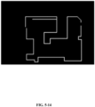
- the optimization of the obstacle zone may specifically include: performing a dilation operation or a profile filling operation on locations corresponding to an ordinary obstacle zone in the second optimized map, to fill a cavity in the second optimized map, and performing a smooth operation on an edge of an explore zone in the second optimized map, to obtain a third optimized map, as shown in FIG. 5- 11; extracting an outer profile of an explore zone in the third optimized map, to obtain a new explore zone profile line, as shown in FIG. 5-12 ; with regard to the new explore zone profile line, performing a straightening operation on an edge of the new explore zone profile line within a margin of error, to obtain a new outer wall zone profile line, as shown in FIG. 5-13 ; with regard to a plurality of key points on the new outer wall zone profile line, searching toward an inside of the third optimized map based on these key points, to obtain a new wall zone profile line, as shown in FIG. 5-14 .
- the locations corresponding to the wall zone and the ordinary obstacle zone are deleted. That is, one or more cavities are created inside the second optimized map at the ordinary obstacle zone. Gaps and holes in the explore zone of the second optimized map may be filled through a dilation operation, and a smooth operation may be performed on the edge of the filled explore zone, to accomplish the optimization of the explore zone. As described in the above embodiment, if the optimized explore zone is correct, it would be located inside the work zone that is surrounded by the wall zone, i.e., each edge would be adjacent to the wall zone. Thus, the new explore zone profile line may be approximately regarded as the new wall zone profile line.
- the edge of the explore zone is consistent with the wall, and in reality, the wall is generally straight.
- the wall may include a smooth curve in rare situations. Therefore, by adjusting the explore zone profile line in the second optimized map, the adjusted explore zone profile line may be used as the new outer wall zone profile line.
- the outer wall zone profile line refers to a profile line of an outermost wall zone of the work zone.
- An inward search may be performed based on a plurality of key points on the outer wall zone profile line. After the location of the wall zone inside the work zone is found in the search, a straightening operation may be performed on wall zone, to obtain a new wall zone profile line, as shown in FIG. 5-14 .
- the above-described optimization of the wall zone may also include: expanding, based on the new outer wall zone profile line, the explore zone of the third optimized map to the new outer wall zone profile line, to obtain an optimized explore zone, and to obtain the optimized map.
- the explore zone of the third optimized map may be further expanded, to accomplish the optimization of the explore zone, thereby obtaining the optimized map of the explore zone, as shown in FIG. 5-15 . As such, the optimization of the explore zone and the wall zone are accomplished.
- the above described expanding, based on the new outer wall zone profile, the explore zone of the third optimized map to the new outer wall zone profile line to obtain the optimized explore zone may include: with regard to a plurality of key points on the new outer wall zone profile line, searching toward an inside of the third optimized map in a predetermined direction based on these key points; labelling non-explore-zone points found in the search as new explore zone points, until points in the explore zone of the third optimized map are found, wherein the new explore zone points and the points in the explore zone of the third optimized map form an optimized explore zone.
- the predetermined direction may be a direction perpendicular to the new outer wall zone profile line, a direction forming a predetermined angle with the new outer wall zone profile line, etc.
- the inward searching process may be similar to the outward expansion shown in FIG. 3 , and FIG. 4 is used to further explain this process.
- each lattice represents a pixel
- number "3" is used to indicate a location point in the explore zone of the third optimized map (which may also be used to represent the "already explored” property)
- number "4" is used to indicate a location point on the new outer wall zone profile line (which may also be used to represent the "wall present” property).
- the inward search may be performed in a predetermined horizontal direction based on points on the new outer wall zone profile line.
- a result of the expansion based on a point on the new outer wall zone profile line is shown in sub-figure "b” of FIG. 4 .
- the newly labelled point is still labelled by number "3,” and the "new" description is only used to distinguish the steps.
- one expansion method is shown for illustrative purposes. The specific expansion method is not limited in the present disclosure.
- FIG. 6 is a schematic illustration of a structure of a map optimization apparatus according to an embodiment of the present disclosure.
- a map optimization apparatus 600 of this embodiment may include: an original map obtaining module 601, an error zone deleting module 602.
- the original map obtaining module 601 may be configured to obtain an original map, the original map including an explore zone, a covered zone, an obstacle zone.
- the error zone deleting module 602 may be configured to determine and delete an error zone from the explore zone in view of the covered zone, the obstacle zone.
- the apparatus 600 may also include: a wall optimization module 603, configured to separate a wall zone from the obstacle zone, and to optimize the wall zone to obtain an optimized map.
- a wall optimization module 603 configured to separate a wall zone from the obstacle zone, and to optimize the wall zone to obtain an optimized map.
- the error zone deleting module 602 may be specifically configured to:
- the error zone deleting module 602 may also be configured to:
- the obstacle zone may also include an ordinary obstacle zone
- the wall optimization module 603 may be specifically configured to:
- the wall optimization module 603 may also be configured to: expand, based on the new outer wall zone profile line, the explore zone in the third optimized map to the new outer wall zone profile line, to obtain an optimized explore zone, and to obtain an optimized map.
- the wall optimization module 603 expands, based on the new outer wall zone profile line, the explore zone in the third optimized map to the new outer wall zone profile line, to obtain the optimized explore zone, it may be specifically configured to: with regard to a plurality of key points on the new outer wall zone profile line, search in a predetermined direction toward an inside of the third optimized map based on the key points, and label non-explore zone points found in the search as new explore zone points, until points in the explore zone of the third optimized map are found, wherein the new explore zone points and the points in the explore zone of the third optimized map form an optimized explore zone.
- the apparatus provided by this embodiment may be configured to execute the method of any of the above embodiments, the realization principle and technical effects are similar, which are not repeated.
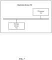
- FIG. 7 is a schematic illustration of a structure of an electronic device, according to an embodiment of the present disclosure.
- an electronic device 700 of this embodiment may include: a storage device 702, a processor 702.
- the storage device 701 may be configured to store program instructions.
- the processor 702 may be configured to retrieve and execute the program instructions from the storage device 701, to execute the method of any of the above embodiments, the realization principle and technical effects are similar, which are not repeated.
- the electronic device of this embodiment may be an autonomous mobile device, or a management system of an autonomous mobile device.
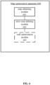
- the present disclosure also provides a computer-readable storage medium, the storage medium stores a computer program.
- the computer program When the computer program is executed by the processor, the method of any of the above embodiments may be executed.
- the present disclosure also provides a computer program product, including a computer program.
- a computer program product including a computer program.
- the computer program is executed by the processor, the method of any of the above embodiments may be realized.
- the above-described program may be stored in a computer-readable storage medium.
- the above-described storage medium may include: various media that can store program codes, such as ROM, RAM, magnetic disks or optic disks.
Landscapes
- Engineering & Computer Science (AREA)
- Remote Sensing (AREA)
- Radar, Positioning & Navigation (AREA)
- Physics & Mathematics (AREA)
- General Physics & Mathematics (AREA)
- Automation & Control Theory (AREA)
- Theoretical Computer Science (AREA)
- Aviation & Aerospace Engineering (AREA)
- Geometry (AREA)
- Computer Vision & Pattern Recognition (AREA)
- Multimedia (AREA)
- Electromagnetism (AREA)
- Control Of Position, Course, Altitude, Or Attitude Of Moving Bodies (AREA)
Abstract
Description
- The present disclosure claims priority to
Chinese patent application No. 202111282907.8, filed on November 1, 2021 - The present disclosure relates to data processing technologies, and in particular, to a map optimization method, an apparatus, an electronic device and a storage medium.
- With the advancement of technology and improvement of living standards, more and more autonomous mobile devices equipped with different functions have entered people's homes, such as cleaning robots, companion mobile robots, which have made people's life more comfortable and convenient.
- An autonomous mobile device refers to a smart device configured to autonomously execute predetermined tasks within a predetermined work zone. Currently, autonomous mobile devices typically include, but are not limited to, cleaning robots (e.g., smart floor sweeping robots, smart floor mopping robots, window cleaning robots), companion mobile robots (e.g., smart electronic pets, nanny robots), service type mobile robots (e.g., reception robots at restaurants, hotels, meeting places), industrial inspection smart devices (e.g., electric power inspection robots, smart forklifts, etc.), security robots (e.g., home or commercial use bodyguard robots), etc.
- An autonomous mobile device typically moves autonomously within a limited space. For example, a cleaning robot, a companion mobile robot typically moves in an indoor space. A service type mobile robot typically moves within a special limited space such as a hotel, a meeting place, etc. This limited space may be referred to as a work zone of the autonomous mobile device.
- Oftentimes, a work zone of an autonomous mobile device is not an open space, but may be divided into different zones, such as multiple rooms, by walls, doors or other obstacles. As the autonomous mobile device moves in a target zone, it creates a map of the target zone. In subsequent operations, it may adjust a moving direction and route based on the created map.
- In the process of the autonomous mobile device creating the map, due to influence of factors such as algorithm localization errors, level of accuracy of localization components, etc., localization data with errors may be generated, causing possible errors in the created map. For example, erroneous zones may appear, erroneous walls may appear, thicknesses of walls may not be consistent. When the autonomous mobile device adjusts the moving direction and route based on the created map, being affected by the errors in the map, it may make erroneous adjustments, thereby reducing the operation efficiency of the autonomous mobile device.
- The present disclosure provides a map optimization method, an apparatus, an electronic device and a storage medium, to solve the above technical problems.
- In a first aspect, the present disclosure provides a map optimization method, including:
- obtaining an original map, the original map including an explore zone, a covered zone, an obstacle zone;
- determining and deleting an error zone from the explore zone in view of the covered zone and the obstacle zone.
- Optionally, the method also includes:
separating a wall zone from the obstacle zone, and optimizing the wall zone, to obtain an optimized map. - Optionally, determining and deleting an error zone from the explore zone in view of the covered zone and the obstacle zone, includes:
- extracting an outer profile of the explore zone, to obtain an explore zone profile line;
- extracting an outer profile of the covered zone, to obtain a covered zone profile line;
- with regard to a plurality of key points on the covered zone profile line, expanding the covered zone outwardly based on these key points until the covered zone touches the obstacle zone and/or the explore zone profile line, to obtain an expanded covered zone;
- with regard to a plurality of key points on the explore zone profile line, searching toward an inside of the explore zone based on these key points, to determine a first error zone, wherein the first error zone is located between the explore zone profile line and the obstacle zone, and has no overlap with the expanded covered zone;
- deleting the first error zone from the explore zone, to obtain a first optimized map.
- Optionally, the method also includes:
- deleting a zone corresponding to the obstacle zone from an explore zone in the first optimized map, to obtain a partitioned map; the partitioned map including a plurality of explore zone blocks;
- determining a second error zone from the plurality of explore zone blocks, wherein the second error zone has no overlap with the covered zone, and has at least one edge that is not adjacent to the obstacle zone;
- deleting the second error zone from the explore zone in the first optimized map, to obtain a second optimized map.
- Optionally, the obstacle zone also includes an ordinary obstacle zone;
- wherein optimizing the wall zone includes:
- performing a dilation operation or a profile filling operation on a location corresponding to the ordinary obstacle zone in the second optimized map, to fill a cavity in the second optimized zone, and performing a smooth operation on an edge of an explore zone in the second optimized map, to obtain a third optimized map;
- extracting an outer profile of an explore zone in the third optimized map, to obtain a new explore zone profile line;
- with regard to the new explore zone profile line, performing a straightening operation on an edge of the new explore zone profile line within a margin of error, to obtain a new outer wall zone profile line;
- with regard to a plurality of key points on the new outer wall zone profile line, searching toward an inside of the third optimized map based on these key points, to obtain a new wall zone profile line.
- Optionally, optimizing the wall zone also includes:
expanding, based on the new outer wall zone profile line, the explore zone in the third optimized map to the new outer wall zone profile line, to obtain an optimized explore zone, and to obtain an optimized map. - Optionally, expanding, based on the new outer wall zone profile line, the explore zone in the third optimized map to the new outer wall zone profile line, to obtain the optimized explore zone, includes:
with regard to a plurality of key points on the new outer wall zone profile line, searching in a predetermined direction toward an inside of the third optimized map based on these key points, and labelling non-explore zone points found in the search as new explore zone points, until points in the explore zone of the third optimized map are found, wherein the new explore zone points and the points in the explore zone of the third optimized map form an optimized explore zone. - In a second aspect, the present disclosure provides a map optimization apparatus, including:
- an original map obtaining module, configured to obtain an original map, wherein the original map includes an explore zone, a covered zone, an obstacle zone;
- an error zone deleting module, configured to determine and delete an error zone from the explore zone in view of the covered zone, the obstacle zone.
- Optionally, the apparatus also includes:
a wall optimization module, configured to separate a wall zone from the obstacle zone, and to optimize the wall zone, to obtain an optimized map. - Optionally, the error zone deleting module is specifically configured to:
- extract an outer profile of the explore zone, to obtain an explore zone profile line;
- extract an outer profile of the covered zone, to obtain a covered zone profile line;
- extract an outer profile of the covered zone, to obtain a covered zone profile line;
- with regard to a plurality of key points on the explore zone profile line, search toward an inside of the explore zone based on these key points, to determine a first error zone, wherein the first error zone is located between the explore zone profile line and the obstacle zone, and has no overlap with the expanded covered zone;
- delete the first error zone in the explore zone, to obtain a first optimized map.
- Optionally, the error zone deleting module is also configured to:
- delete a zone corresponding to the obstacle zone from an explore zone in the first optimized map, to obtain a partitioned map; the partitioned map including a plurality of explore zone blocks;
- determine a second error zone from the plurality of explore zone blocks, wherein the second error zone has no overlap with the covered zone, and has at least one edge that is not adjacent to the obstacle zone;
- delete the second error zone from the explore zone in the first optimized map, to obtain a second optimized map.
- Optionally, the obstacle zone also includes an ordinary obstacle zone;
- The wall optimization module is specifically configured to:
- perform a dilation operation or a profile filling operation on a location corresponding to the ordinary obstacle zone in the second optimized map, to fill a cavity in the second optimized zone, and perform a smooth operation on an edge of an explore zone in the second optimized map, to obtain a third optimized map;
- extract an outer profile of an explore zone in the third optimized map, to obtain a new explore zone profile line;
- with regard to the new explore zone profile line, perform a straightening operation on an edge of the new explore zone profile line within a margin of error, to obtain a new outer wall zone profile line;
- with regard to a plurality of key points on the new outer wall zone profile line, search toward an inside of the third optimized map based on the key points, to obtain a new wall zone profile line.
- Optionally, the wall optimization module is also specifically configured to:
expand, based on the new outer wall zone profile line, the explore zone in the third optimized map to the new outer wall zone profile line, to obtain an optimized explore zone, and to obtain an optimized map. - Optionally, when the wall optimization module is configured to expand, based on the new outer wall zone profile line, the explore zone in the third optimized map to the new outer wall zone profile line, to obtain the optimized explore zone, the wall optimization module is specifically configured to:
with regard to a plurality of key points on the new outer wall zone profile line, search in a predetermined direction toward an inside of the third optimized map based on the key points, and label non-explore zone points found in the search as new explore zone points, until points in the explore zone of the third optimized map are found, wherein the new explore zone points and the points in the explore zone of the third optimized map form an optimized explore zone. - In a third aspect, the present disclosure provides an electronic device, including: a storage device, configured to store program instructions; a processor, configured to retrieve and execute the program instructions from the storage device, to perform the method according to the first aspect.
- In a fourth aspect, the present disclosure provides a computer-readable storage medium. The storage medium stores a computer program. When the computer program is executed by the processor, the method according to the first aspect is performed.
- In a fifth aspect, the present disclosure provides a program product, including a computer program. When the computer program is executed by the processor, the method according to the first aspect is performed.
- The present disclosure provides a map optimization method, an apparatus, an electronic device and a storage medium. The map optimization method includes: obtaining an original map, the original map including an explore zone, a covered zone, an obstacle zone; determining and deleting an error zone from the explore zone in view of the covered zone and the obstacle zone. According to the technical solution of the present disclosure, in view of points in zones of different properties in the original map, and the localization principle, an error zone is determined and deleted from the original map, thereby realizing the optimization of the original map, such that the optimized map is closer to the actual map. This enables the autonomous mobile device to execute tasks more efficiently based on the optimized map.
- To explain more clearly the technical solutions of the present disclosure or of the existing technologies, the accompanying drawings that are used in the description of the embodiments or the existing technologies are briefly introduced. Obviously, the accompanying drawings described below show some embodiments of the present disclosure. For a person having ordinary skills in the art, other accompanying drawings may be obtained based on these accompanying drawings without expending creative effort.
-
FIG. 1 is a schematic illustration of an application scene of the present disclosure; -
FIG. 2 is a flowchart illustrating a map optimization method, according to an embodiment of the present disclosure; -
FIG. 3 is a schematic illustration of expansion of a covered zone, according to an embodiment of the present disclosure; -
FIG. 4 is a schematic illustration of expansion of an explore zone in a third optimized map, according to an embodiment of the present disclosure; -
FIGs. 5-1 to 5-16 are schematic illustrations of actual processing steps according to an embodiment of the present disclosure; -
FIG. 6 is a schematic illustration of a structure of a map optimization apparatus, according to an embodiment of the present disclosure; -
FIG. 7 is a schematic illustration of a structure of an electronic device, according to an embodiment of the present disclosure; -
FIG. 8 is a schematic illustration of a certain profile, according to an embodiment of the present disclosure. - In order for the objective, technical solutions, and advantages of the present disclosure to become clearer, next, with reference to the accompanying drawings of the embodiments of the present disclosure, the technical solutions of the embodiments of the present disclosure will be described clearly and comprehensively. The described embodiments are only some embodiments of the present disclosure, and are not all of the embodiments of the present disclosure. Based on the embodiments of the present disclosure, a person having ordinary skills in the art can obtain other embodiments without spending creative efforts. Such embodiments also fall into the protection scope of the present disclosure.
- Typically, an autonomous mobile device is equipped with various types of sensors configured to explore an inner space of a work zone, and based on sensor data, the autonomous mobile device can create a work zone map or adjust a moving direction and route, etc.
- In the process of creating the map, direct localization and indirect localization may be involved. Direct localization means that localization information of the autonomous mobile device is directly used as the points in the map. For example, using dead reckoning sensors (sometimes in combination with cameras or light detection and ranging (Lidar) sensors) such as an encoder wheel, a gyroscope, an accelerometer, etc., location coordinates (localization information) of the current location of the autonomous mobile device may be computed in real time through a Simultaneous Localization And Mapping (SLAM) algorithm. The location coordinates may correspond to corresponding points in the map. Alternatively, thought a collision sensor provided at the front portion of the autonomous mobile device, location coordinates when the autonomous mobile device touches an obstacle (objects in the work zone that block the movement of the autonomous mobile device, such as walls and ordinary obstacles, for example, furniture, etc.) may be detected. The location coordinates may correspond to corresponding points in the map. Indirect localization means points in the map may be indirectly calculated based on the localization information of the autonomous mobile device and the work principle of a light detection and ranging (Lidar) sensor. For example, after obtaining the location coordinates (localization information) of the autonomous mobile device, based on light detection and ranging (Lidar) disposed at the top and/or sides of the autonomous mobile device (e.g., Lidar, Time of Flight (TOF) sensor, or infrared diodes, etc.), an obstacle that forms a certain relative angle and has a certain distance with respect to the autonomous mobile device may be detected in a contactless manner. As such, location coordinates of the detected obstacle may be indirectly calculated based on the location coordinates of the autonomous mobile device itself and the relative angle and distance of the detected obstacle with respect to the autonomous mobile device. The location coordinates of the detected obstacle may correspond to corresponding points in the map. For the space between the autonomous mobile device and the detected obstacle, because a detecting light of the light detection and ranging (Lidar) sensor passes through the space, the space also corresponds to corresponding points in the map. Certain errors may exist in these two localization methods, which may cause the ultimately created map to have some differences from the actual map, i.e., the created map may not be accurate. For example, surplus zones may exist in the created map, or the walls in the map may be irregular, etc. As such, when the created map is used as a basis for planning a moving route or for adjusting the moving direction, erroneous planning may occur, which may reduce the work efficiency of the autonomous mobile device.
- Errors may exist in the original map of the autonomous mobile device due to errors in the localization performed through an algorithm or due to factors of a localization device itself. For example, the map may have an erroneous zone or an erroneous wall, or the thicknesses of the walls may be different, the walls may be curved, etc. The technical issues to be addressed by the present disclosure primarily include:
- 1) deleting zones that are erroneously created from the original map, while ensuring the integrity of the original information of the original map.
- 2) optimizing walls in the original map, such that the thicknesses of walls in the map are consistent, which are convenient for display.
- 3) straightening the walls in the map within a certain error range, which solves the issues relating to the walls in the map being not straight caused by the localization errors.
- Existing technology typically extracts wall information from obstacles in the original map, and optimizes the walls through curve fitting or straight line detection. However, because the actual work zone environment is relatively complex, especially when the room has a relatively large number of obstacles, errors can easily occur in curve fitting, and it is also difficult to detect straight lines. In the meantime, localization of the autonomous mobile device may have errors, causing error zones to appear in the original map. Existing technology cannot recognize the error zones, and therefore, cannot delete these error zones.
- As such, the present disclosure provides a map optimization method, an apparatus, an electronic device and a storage medium, to further optimize and adjust the created map, such that the optimized map is closer to the actual map, thereby avoiding map inaccuracy and low work efficiency caused by errors in the map.
-
FIG. 1 is a schematic illustration of an application scene of the present disclosure. As shown inFIG. 1 , if the autonomous mobile device is acleaning robot 101, it may be configured to perform indoor cleaning tasks. In initial operations, the cleaningrobot 101 may traverse the indoor space (i.e., cleaning the indoor floor) to create an original map of a work zone. After creating the original map in view of various sensor information, the method of the present disclosure may be used to optimize the original map, to obtain an optimized map. Subsequently, the optimized map may be used as a basis for the route planning, and subsequent cleaning tasks may be performed. The specific optimization process can refer to the following various embodiments. -
FIG. 2 is a flowchart illustrating a map optimization method, according to an embodiment of the present disclosure. As shown inFIG. 2 , the method of this embodiment may include:
S201, obtaining an original map, the original map including an explore zone, a covered zone, an obstacle zone (including a wall zone). - In some embodiments, the map optimization method may be executed after the autonomous mobile device has moved within the work zone and created the map of the work zone. Here, the obtained original map refers to a map created during the movement of the autonomous mobile.
- Specifically, in the map creation process, initially, all locations may be set as unexplored zones. The autonomous mobile device moves in the work zone. Whenever the autonomous mobile device arrives at a location point, the autonomous mobile device re-determines properties of this location point. Alternatively, based on a trajectory traversed by the autonomous mobile device within a time period, properties of each location point on the trajectory may be re-determined.
- In the map that is being created or that has been created, properties of each location point may be one or more of unexplored, already explored, already covered, obstacle present, etc. Here, an unexplored location point is a location point that has not been detected by the autonomous mobile device through direct localization or indirect localization. Correspondingly, an already explored location point is a location point that has been previously detected by the autonomous mobile device through direct localization or indirect localization, such as a location that the autonomous mobile device actually reached, and a space that the detecting light of the light detection and ranging (Lidar) sensor of the autonomous mobile device can pass through, and locations of obstacles that can reflect the detecting light. An already covered location point is a location point that has been detected through direct localization, which is also a location that the autonomous mobile device actually reached. From the above descriptions, it can be seen that an already covered location point may also be an already explored location point, but an already explored location point may not necessarily be an already covered location point. An obstacle present location point is a location point where an obstacle may be detected and recognized by the autonomous mobile device through direct localization or indirect localization, which typically includes a location point determined in view of signals obtained by components such as a collision sensor, a wheel drop sensor. To implement the map optimization method of the present disclosure, it may be needed to separate location points corresponding to walls from location points of the obstacles. From the above-described definition of the obstacle present location points, it can be derived that location points of the walls are location points of walls that may be detected and recognized by the autonomous mobile device through direct localization or indirect localization. After the location points of the walls are separated from the obstacle present location points, the remaining location points are ordinary obstacle present location points. Actually, a wall is a type of a special obstacle. Wall present location points may be separated from the obstacle present location points based on information obtained from various sensors. For example, according to the above-described definitions of direct localization and indirect localization, it may be determined whether an obtained obstacle present location point is a wall present location point based on the information obtained through various sensors. Different values may be assigned to these two types of location points. For example, a wall present location point may be assigned with 100, and a location point where an obstacle of other types exist may be assigned with 85, thereby differentiating the two types of location points. In some embodiments, in the obtained original map or during the process of creating the original map, ordinary obstacle present location points and wall present location points may have already been separated and marked. In other embodiments, after obtaining the original map, wall present location points may be separated from obstacle present location points in the original map. The specific separating methods for separating the ordinary obstacle present location points and wall present location points are not issues to be addressed by the present disclosure, but are premises of the map optimization method of the present disclosure. Related separating methods may have various forms in the existing technology, some can refer to Chinese Patent Applications that are published as
CN113064413A ,CN111862133A . - As seen from the above descriptions, properties of each location point may be determined in view of various data generated in the map creation process.
- The autonomous mobile device may create the map of the target zone while moving in the target zone. To differentiate between the unexplored location points, the already explored location points, the already covered location points, the obstacle present location points (including wall present location points and ordinary obstacle present location points) in the map, these locations are displayed in the map using different pixel values. For example, the pixel value for an unexplored location point may be 75, the pixel value for an already explored location point may be 25, the pixel value for an already covered location point may be 0, the pixel value for an ordinary obstacle present location point may be 85, and the pixel value for a created wall present location point may be 100. The original map is shown in
FIG. 5-1 . - Further, based on the property of each location point, all location points in the map may be divided into a plurality of zones, at least including an explore zone, a covered zone, an obstacle zone (including a wall zone and/or an ordinary obstacle zone). Here, the explore zone may be a zone formed by all already explored location points, and the explore zone may represent the maximum range the autonomous mobile device can detect (including zones that can be determined through direct localization and indirect localization). The covered zone may be a zone formed by all already covered location points, and the covered zone may represent a zone that the autonomous mobile device can actually reach. The obstacle zone may be a zone formed by all obstacle present location points, and the obstacle zone may be a zone that the autonomous mobile device cannot pass through, regardless of whether the autonomous mobile device has attempted to pass through this zone. The obstacle zone may be specifically divided into a wall zone and an ordinary obstacle zone. The wall zone may be a zone formed by all wall present location points.
FIG. 5-2 schematically depicts the explore zone, the covered zone, the ordinary obstacle zone, the wall zone. It should be noted that because in the actual map, the shape and distribution of each zone are complex,FIG. 5-2 is only illustrative, and does not list all explore zones, covered zones, ordinary obstacle zones, wall zones. In addition, some selection boxes include not just one type of zone, but a mixture or overlap of multiple types of zones. The displayed zone is only the main zone type or representative zone type in the selection box. Thus,FIG. 5-2 does not intend to impose limitations on the above various types of zones. - In other embodiments, in a work zone where the autonomous mobile device previously operated and created a map, the map optimization method may be executed separately. In this case, the obtained original map may be the already created map. The created map (or referred to as a historical map) may be previously created by the autonomous mobile device and stored in the autonomous mobile device or in a server. The created map may also be a historical map created by another autonomous mobile device when operating in the same work zone and stored in the server. For example, if a home has a floor sweeping robot and a floor mopping robot, because the robots both perform cleaning of the floors of the rooms of the same home, the work zones of the two devices are the same. The floor sweeping robot may store a map of the rooms of the home created during its operation in a server. Although the floor mopping robot may not have been operated in this work zone itself, it can obtain the historical map of the work zone of the rooms of the home directly from the server.
- The name of each location point and the name of each zone used in the present disclosure may use other definitions. However, the sources of data referred to by the names are deterministic.
- S202, determining and deleting an error zone from the explore zone in view of the covered zone, the obstacle zone (including at least the wall zone).
- Based on the description of each property of a location point, it may be determined that overlap may occur between various zones. Here, the explore zone may have the largest area, which would likely have an overlap with the covered zone, the obstacle zone. A wall zone in the obstacle zone is a boundary of the work zone. The covered zone exists inside the work zone that is surrounded by the wall zone(s). Because the explore zone includes location points detected or calculated through indirect localization by sensors of the autonomous mobile device, this zone most likely has an error zone caused by environmental influence, sensor errors, and/or calculation inaccuracy. Actually, affected by the working principle of the sensors, a location point determined by a distance-measuring sensor such as a Lidar can easily be affected by the environment of the work zone. For example, if there is a mirror in a transmitting direction of a detecting light, the Lidar would likely be affected by the mirror reflection, the refraction of the detecting light, which can cause errors in the distance measurement. As such, the explore zone in the original map may be optimized.
- It may be determined from the above analysis that the location points outside of the obstacle zone in the explore zone belong to the error zone. These location points may be deleted to achieve the optimization of the explore zone.
- The map optimization method provided by the present disclosure includes: obtaining an original map, the original map including an explore zone, a covered zone, an obstacle zone (including at least a wall zone); determining and deleting an error zone from the explore zone in view of the covered zone, the obstacle zone. In the technical solution of the present disclosure, in view of the points in zones having different properties in the original map, and their localization principles, the error zone is determined and deleted from the original map, thereby accomplishing the optimization of the original map, such that it is closer to the actual map, which enables the autonomous mobile device to more efficiently execute tasks based on the optimized map.
- To further optimize the map, a wall zone may be separated from the obstacle zone, and the wall zone may be optimized, to obtain an optimized map.
- By optimizing the wall, the wall in the original map becomes closer to the actual situation, and the map is further improved.
- In some embodiments, the above-described determining and deleting the error zone from the explore zone in view of the covered zone, the obstacle zone, may also include: extracting an outer profile of the explore zone as shown in
FIG. 5-3 , to obtain an explore zone profile line as shown inFIG. 5-4 ; extracting an outer profile of the covered zone (as shown inFIG. 5-5 ), to obtain a covered zone profile line (the profile line formed at the border between the black and white portions as shown inFIG. 5-5 ); with respect to a plurality of key points on the covered zone profile line, expanding the covered zone outwardly based on these key points until the covered zone touches the obstacle zone and/or the explore zone, to obtain an expanded covered zone, as shown inFIG. 5-6 ; with respect to a plurality of key points on the explore zone profile line, searching toward an inside of the explore zone based on these key points, to determine a first error zone, wherein the first error zone is located between the explore zone profile line and the obstacle zone, and has no overlap with the expanded covered zone, as indicated inFIG. 5-3 ; deleting the first error zone from the explore zone, to obtain a first optimized map, as shown inFIG. 5-7 . Here the key points refer to points that have a key function in forming the profile of a certain zone or those adjacent such points; a plurality of key points means that, to form the profile of the above-described certain zone, at least a plurality of key points are needed to form the profile of the certain zone. For example, for a triangular profile, the three vertex points / points adjacent to the vertex points of the triangular profile are key points, and a plurality of key points that can form the triangular profile include at least these three points; for a rectangular profile, the four vertex points / points adjacent to the vertex points of the rectangle are key points, and a plurality of key points that can form the rectangular profile include at least these four points; for the profile having the shape shown inFIG. 8 , six vertex points A1, B1, C1, D1, E1, F1 or their adjacent points A2, B2, C2, D2, E2, F2 shown inFIG. 8 are key points, and a plurality of key points that can form this profile include at least six points: at least one point from A1 or A2, at least one point from B1 or B2, at least one point from C1 or C2, at least one point from D1 or D2, at least one point from E1 or E2, at least one point from F1 or F2. - Specifically, one or more pixels may be used as the width standard for the profile line. For example, location points in the explore zone that are adjacent to the unexplored zone may be used to form the explore zone profile line (width is one pixel).
- Further, the covered zone may be expanded. Similarly, location points in the covered zone that are adjacent to other zones may be extracted to form the covered zone profile line (width is one pixel), and the covered zone may be expanded outwardly at least based on a plurality of key points on the covered zone profile line. The condition for stopping the expansion may be touching the profile line of the obstacle zone and/or the explore zone.
- In the present disclosure, expanding outwardly based on certain point means assigning one or more properties of this point to all location points on a segment that extends in a predetermine direction from this point as a starting point to a target point. This will be explained in detail with reference to the example shown in
FIG. 3 . As shown in sub-figure "a" ofFIG. 3 , each lattice represents a pixel, number "1" is used to indicate a location point in the covered zone (which may also be used to represent the property of "already covered"), number "2" is used to indicate a location point in the wall zone (which may also be used to represent the property of "wall present"). Points on the covered zone profile line may be expanded in a predetermined horizontal direction. A result of the expansion based on one of the points on the covered zone profile line is shown in sub-figure "b" ofFIG. 3 . The expansion shown here is only an example expansion method, which does not limit the specific expansion method to be used. - In some other scenes, the expansion of the covered zone based on the points on the covered zone profile line may be performed along a certain pre-set angle or multiple pre-set angles. The advantage of this type of expansion is, even when the wall zone is discontinuous and has break points, the expanded covered zone does not extend unlimitedly.
- Points in the covered zone are locations actually reached by the autonomous mobile device, and may not necessarily represent all of the space outside of the obstacle zone in the work zone. As such, the expanded covered zone obtained through expansion are locations that actually can be reached by the autonomous mobile device determined based on the original map using an algorithm. Further, with respect to a plurality of key points on the explore zone profile line, searching toward an inside of the explore zone based on these key points may be performed. In the searching process, if the obstacle zone is first encountered, a zone between the explore zone profile line and the encountered obstacle zone may be determined as a first error zone; with respect to a plurality of key points on the explore zone profile line, searching toward an inside of the explore zone based on these key points may be performed. In the searching process, if the expanded covered zone is first encountered, a zone between the explore zone profile line and the encountered expanded covered zone does not belong to the expanded covered zone. The first error zone may be deleted from the explore zone, to obtain a first optimized map.
- It should be noted that, the "first error zone" used herein is only for the purpose of indicating an error zone having such properties, in order to distinguish from error zones determined using other conditions, and this term should not limit the present disclosure.
- In the process of expanding the covered zone, if the obstacle zone is discontinuous and has break points, the expanded covered zone may extend such that some error zones may overlap the expanded covered zone, which may not be deleted through the above steps. Therefore, the following steps may be further executed: deleting a zone corresponding to the obstacle zone from the explore zone in the first optimized map, to obtain a partitioned map, as shown in
FIG. 5-9 ; a zone corresponding to the obstacle zone in the first optimized map is an obstacle zone map, as shown inFIG. 5-8 ; the partitioned map includes a plurality of explore zone blocks; a second error zone may be determined from the plurality of explore zone blocks; the second error zone may have no overlap with the covered zone, and may have at least one edge that is not adjacent to the obstacle zone, as shown inFIG. 5-9 . The second error zone may be deleted from the explore zone in the first optimized map, and the resulting explore zone may be superposed with the obstacle zone map, to obtain a second optimized map, as shown inFIG. 5- 10. - First, by deleting the zone corresponding to the obstacle zone, i.e., the obstacle zone map, as shown in
FIG. 5-8 , the explore zone becomes a partitioned map, as shown inFIG. 5-9 . It can be understood that, if a block is correct, it would be located inside a work zone that is surrounded by the wall zone. That is, each edge of the block is adjacent to the obstacle zone. Therefore, a block having no overlap with the covered zone and having at least one edge that is not adjacent to the obstacle zone, is the second error zone. The second error zone may be deleted from the explore zone, to obtain the second optimized map, as shown inFIG. 5-10 . - In some embodiments, to make the partition between the blocks clearer, after the zone corresponding to the obstacle zone is deleted from the explore zone in the first optimized map, an etching operation may be performed. Correspondingly, after deleting the second error zone, a dilation operation may be performed.
- After deleting the error zone, the wall may be further optimized. The optimization of the obstacle zone may specifically include: performing a dilation operation or a profile filling operation on locations corresponding to an ordinary obstacle zone in the second optimized map, to fill a cavity in the second optimized map, and performing a smooth operation on an edge of an explore zone in the second optimized map, to obtain a third optimized map, as shown in
FIG. 5- 11; extracting an outer profile of an explore zone in the third optimized map, to obtain a new explore zone profile line, as shown inFIG. 5-12 ; with regard to the new explore zone profile line, performing a straightening operation on an edge of the new explore zone profile line within a margin of error, to obtain a new outer wall zone profile line, as shown inFIG. 5-13 ; with regard to a plurality of key points on the new outer wall zone profile line, searching toward an inside of the third optimized map based on these key points, to obtain a new wall zone profile line, as shown inFIG. 5-14 . - After deleting the zone corresponding to the obstacle zone, the locations corresponding to the wall zone and the ordinary obstacle zone are deleted. That is, one or more cavities are created inside the second optimized map at the ordinary obstacle zone. Gaps and holes in the explore zone of the second optimized map may be filled through a dilation operation, and a smooth operation may be performed on the edge of the filled explore zone, to accomplish the optimization of the explore zone. As described in the above embodiment, if the optimized explore zone is correct, it would be located inside the work zone that is surrounded by the wall zone, i.e., each edge would be adjacent to the wall zone. Thus, the new explore zone profile line may be approximately regarded as the new wall zone profile line. In the actual map, in ideal situations, the edge of the explore zone is consistent with the wall, and in reality, the wall is generally straight. The wall may include a smooth curve in rare situations. Therefore, by adjusting the explore zone profile line in the second optimized map, the adjusted explore zone profile line may be used as the new outer wall zone profile line. The outer wall zone profile line refers to a profile line of an outermost wall zone of the work zone. An inward search may be performed based on a plurality of key points on the outer wall zone profile line. After the location of the wall zone inside the work zone is found in the search, a straightening operation may be performed on wall zone, to obtain a new wall zone profile line, as shown in
FIG. 5-14 . - The above-described optimization of the wall zone may also include: expanding, based on the new outer wall zone profile line, the explore zone of the third optimized map to the new outer wall zone profile line, to obtain an optimized explore zone, and to obtain the optimized map.
- After adjusting the wall zone profile line, a gap may be created between the adjusted wall zone profile line and the explore zone of the third optimized map. Therefore, the explore zone of the third optimized map may be further expanded, to accomplish the optimization of the explore zone, thereby obtaining the optimized map of the explore zone, as shown in
FIG. 5-15 . As such, the optimization of the explore zone and the wall zone are accomplished. - Specifically, the above described expanding, based on the new outer wall zone profile, the explore zone of the third optimized map to the new outer wall zone profile line to obtain the optimized explore zone, may include: with regard to a plurality of key points on the new outer wall zone profile line, searching toward an inside of the third optimized map in a predetermined direction based on these key points; labelling non-explore-zone points found in the search as new explore zone points, until points in the explore zone of the third optimized map are found, wherein the new explore zone points and the points in the explore zone of the third optimized map form an optimized explore zone.
- Here, the predetermined direction may be a direction perpendicular to the new outer wall zone profile line, a direction forming a predetermined angle with the new outer wall zone profile line, etc.
- The inward searching process may be similar to the outward expansion shown in
FIG. 3 , andFIG. 4 is used to further explain this process. As shown in sub-figure "a" ofFIG. 4 , each lattice represents a pixel, number "3" is used to indicate a location point in the explore zone of the third optimized map (which may also be used to represent the "already explored" property), number "4" is used to indicate a location point on the new outer wall zone profile line (which may also be used to represent the "wall present" property). The inward search may be performed in a predetermined horizontal direction based on points on the new outer wall zone profile line. A result of the expansion based on a point on the new outer wall zone profile line is shown in sub-figure "b" ofFIG. 4 . The newly labelled point is still labelled by number "3," and the "new" description is only used to distinguish the steps. Here only one expansion method is shown for illustrative purposes. The specific expansion method is not limited in the present disclosure. - In the optimized explore zone map shown in
FIG. 5-15 , superposing the covered zone shown inFIG. 5-5 and the new wall zone profile line shown inFIG. 5-14 , the ultimate optimized map shown inFIG. 5-16 may be obtained. -
FIG. 6 is a schematic illustration of a structure of a map optimization apparatus according to an embodiment of the present disclosure. As shown inFIG. 6 , a map optimization apparatus 600 of this embodiment may include: an originalmap obtaining module 601, an errorzone deleting module 602. - The original
map obtaining module 601 may be configured to obtain an original map, the original map including an explore zone, a covered zone, an obstacle zone. - The error
zone deleting module 602 may be configured to determine and delete an error zone from the explore zone in view of the covered zone, the obstacle zone. - Optionally, the apparatus 600 may also include:
awall optimization module 603, configured to separate a wall zone from the obstacle zone, and to optimize the wall zone to obtain an optimized map. - Optionally, the error
zone deleting module 602 may be specifically configured to: - extract an outer profile of the explore zone, to obtain an explore zone profile line;
- extract an outer profile of the covered zone, to obtain a covered zone profile line;
- with regard to a plurality of key points on the covered zone profile line, expand the covered zone outwardly based on these key points until the covered zone touches the explore zone profile line, to obtain an expanded covered zone;
- with regard to a plurality of key points on the explore zone profile line, search toward an inside of the explore zone based on the key points, to determine a first error zone, wherein the first error zone is located between the explore zone profile line and the obstacle zone, and has no overlap with the expanded covered zone;
- delete the first error zone from the explore zone, to obtain a first optimized map.
- Optionally, the error
zone deleting module 602 may also be configured to: - delete a zone corresponding to the obstacle zone from the explore zone in the first optimized map, to obtain a partitioned map; the partitioned map including a plurality of explore zone blocks;
- determine a second error zone from a plurality of explore zone blocks, the second error zone having no overlap with the covered zone, and having at least one edge that is not adjacent to the obstacle zone;
- delete the second error zone from the explore zone in the first optimized map, to obtain a second optimized map.
- Optionally, the obstacle zone may also include an ordinary obstacle zone;
- The
wall optimization module 603 may be specifically configured to: - perform a dilation operation or a profile filling operation on locations corresponding to an ordinary obstacle zone in the second optimized map, to fill a cavity in the second optimized map, and perform a smooth operation on an edge of an explore zone in the second optimized map, to obtain a third optimized map;
- extract an outer profile of the explore zone in the third optimized map, to obtain a new explore zone profile line;
- with regard to the new explore zone profile line, perform a straightening operation on an edge of the new explore zone profile line within a margin of error, to obtain a new outer wall zone profile line;
- with regard to a plurality of key points on the new outer wall zone profile line, search toward an inside of the third optimized map based on the key points, to obtain a new outer wall zone profile line.
- Optionally, the
wall optimization module 603 may also be configured to:
expand, based on the new outer wall zone profile line, the explore zone in the third optimized map to the new outer wall zone profile line, to obtain an optimized explore zone, and to obtain an optimized map. - Optionally, when the
wall optimization module 603 expands, based on the new outer wall zone profile line, the explore zone in the third optimized map to the new outer wall zone profile line, to obtain the optimized explore zone, it may be specifically configured to:
with regard to a plurality of key points on the new outer wall zone profile line, search in a predetermined direction toward an inside of the third optimized map based on the key points, and label non-explore zone points found in the search as new explore zone points, until points in the explore zone of the third optimized map are found, wherein the new explore zone points and the points in the explore zone of the third optimized map form an optimized explore zone. - The apparatus provided by this embodiment may be configured to execute the method of any of the above embodiments, the realization principle and technical effects are similar, which are not repeated.
-
FIG. 7 is a schematic illustration of a structure of an electronic device, according to an embodiment of the present disclosure. As shown inFIG. 7 , anelectronic device 700 of this embodiment may include: astorage device 702, aprocessor 702. - The
storage device 701 may be configured to store program instructions. - The
processor 702 may be configured to retrieve and execute the program instructions from thestorage device 701, to execute the method of any of the above embodiments, the realization principle and technical effects are similar, which are not repeated. - The electronic device of this embodiment may be an autonomous mobile device, or a management system of an autonomous mobile device.
- The present disclosure also provides a computer-readable storage medium, the storage medium stores a computer program. When the computer program is executed by the processor, the method of any of the above embodiments may be executed.
- The present disclosure also provides a computer program product, including a computer program. When the computer program is executed by the processor, the method of any of the above embodiments may be realized.
- A person having ordinary skills in the art can appreciate: all or some steps of the method embodiments can be implemented through hardware related to computer instructions. The above-described program may be stored in a computer-readable storage medium. When the program is executed, the steps of the method of the above various embodiments can be executed. The above-described storage medium may include: various media that can store program codes, such as ROM, RAM, magnetic disks or optic disks.
- Finally, it should be noted that: the above embodiments are only used to explain the technical solutions of the present disclosure, and are not to limit the present disclosure; although detailed explanations have been provided for the present disclosure with reference to the above various embodiments, a person having ordinary skills in the art should understand: the person having ordinary skills in the art can modify the technical solutions described in the above various embodiments, or carry out equivalent replacement to some or all technical features. These modifications or replacements do not render relevant technical solutions to deviate from the scope of the technical solutions of various embodiments of the present disclosure.
Claims (11)
- A map optimization method, comprising:obtaining an original map, the original map including an explore zone, a covered zone, an obstacle zone;determining and deleting an error zone from the explore zone in view of the covered zone, the obstacle zone.
- The method according to claim 1, characterized in there, also comprising:
separating a wall zone from the obstacle zone, and optimizing the wall zone to obtain an optimized map. - The method according to claim 2, characterized in that, determining and deleting the error zone from the explore zone in view of the covered zone, the obstacle zone, includes:extracting an outer profile of the explore zone, to obtain an explore zone profile line;extracting an outer profile of the covered zone, to obtain a covered zone profile line;with regard to a plurality of key points on the covered zone profile line, expanding the covered zone outwardly based on the key points until the covered zone touches the obstacle zone and/or the explore zone profile line, to obtain an expanded covered zone;with regard to a plurality of key points on the explore zone profile line, searching toward an inside of the explore zone based on the key points, to determine a first error zone, wherein the first error zone is located between the explore zone profile line and the obstacle zone, and has no overlap with the expanded covered zone;deleting the first error zone from the explore zone, to obtain a first optimized map.
- The method according to claim 3, characterized in that, further comprising:deleting a zone corresponding to the obstacle zone from an explore zone in the first optimized map, to obtain a partitioned map; the partitioned map including a plurality of explore zone blocks;determining a second error zone from the plurality of explore zone blocks, wherein the second error zone has no overlap with the covered zone, and has at least one edge that is not adjacent to the obstacle zone;deleting the second error zone from the explore zone in the first optimized map, to obtain a second optimized map.
- The method according to claim 4, characterized in that, the obstacle zone includes an ordinary obstacle zone;
wherein optimizing the wall zone includes:performing a dilation operation or a profile filling operation on a location corresponding to the ordinary obstacle zone in the second optimized map, to fill a cavity in the second optimized zone, and performing a smooth operation on an edge of an explore zone in the second optimized map, to obtain a third optimized map;extracting an outer profile of an explore zone in the third optimized map, to obtain a new explore zone profile line;with regard to the new explore zone profile line, performing a straightening operation on an edge of the new explore zone profile line within a margin of error, to obtain a new outer wall zone profile line;with regard to a plurality of key points on the new outer wall zone profile line, searching toward an inside of the third optimized map based on the key points, to obtain a new wall zone profile line. - The method according to claim 5, characterized in that, optimizing the wall zone also includes:
expanding, based on the new outer wall zone profile line, the explore zone in the third optimized map to the new outer wall zone profile line, to obtain an optimized explore zone, and to obtain an optimized map. - The method according to claim 6, characterized in that, expanding, based on the new outer wall zone profile line, the explore zone in the third optimized map to the new outer wall zone profile line, to obtain an optimized explore zone, includes:
with regard to a plurality of key points on the new outer wall zone profile line, searching in a predetermined direction toward an inside of the third optimized map based on the key points, and labelling non-explore zone points found in the search as new explore zone points, until points in the explore zone of the third optimized map are found, wherein the new explore zone points and the points in the explore zone of the third optimized map form an optimized explore zone. - A map optimization apparatus, comprising:an original map obtaining module configured to obtain an original map, the original map including an explore zone, a covered zone, an obstacle zone;an error zone deleting module configured to determine and delete an error zone from the explore zone in view of the covered zone, the obstacle zone.
- An electronic device, comprising:a storage device configured to store program instructions;a processor configured to retrieve and execute the program instructions from the storage device, to execute the method according any of the claims 1-7.
- A computer-readable storage medium, the storage medium storing a computer program, when the computer program is executed by a processor, the method according to any of claims 1-7 is performed.
- A computer program product, comprising a computer program, when the computer program is executed by a processor, the method according to any of claims 1-7 is performed.
Applications Claiming Priority (2)
| Application Number | Priority Date | Filing Date | Title |
|---|---|---|---|
| CN202111282907.8A CN116069006B (en) | 2021-11-01 | 2021-11-01 | Map optimization methods, devices, electronic equipment and storage media |
| PCT/CN2022/126588 WO2023071922A1 (en) | 2021-11-01 | 2022-10-21 | Map optimization method and apparatus, and electronic device and storage medium |
Publications (2)
| Publication Number | Publication Date |
|---|---|
| EP4428822A1 true EP4428822A1 (en) | 2024-09-11 |
| EP4428822A4 EP4428822A4 (en) | 2025-10-15 |
Family
ID=86159049
Family Applications (1)
| Application Number | Title | Priority Date | Filing Date |
|---|---|---|---|
| EP22885799.1A Pending EP4428822A4 (en) | 2021-11-01 | 2022-10-21 | Map optimization method and device, as well as electronic device and storage medium |
Country Status (4)
| Country | Link |
|---|---|
| US (1) | US20240281001A1 (en) |
| EP (1) | EP4428822A4 (en) |
| CN (1) | CN116069006B (en) |
| WO (1) | WO2023071922A1 (en) |
Family Cites Families (15)
| Publication number | Priority date | Publication date | Assignee | Title |
|---|---|---|---|---|
| JP5287050B2 (en) * | 2008-09-03 | 2013-09-11 | 村田機械株式会社 | Route planning method, route planning device, and autonomous mobile device |
| DE102012217282B4 (en) * | 2012-09-25 | 2023-03-02 | Trimble Jena Gmbh | Method and device for assigning measuring points to a set of fixed points |
| CN107121142B (en) * | 2016-12-30 | 2019-03-19 | 深圳市杉川机器人有限公司 | Topological map creation method and navigation method of mobile robot |
| KR20190023835A (en) * | 2017-08-30 | 2019-03-08 | 엘지전자 주식회사 | Method of space partitioning-working by multi-robot and robot implementing thereof |
| DE102018121365A1 (en) * | 2018-08-31 | 2020-04-23 | RobArt GmbH | EXPLORATION OF A ROBOT APPLICATION AREA BY AN AUTONOMOUS MOBILE ROBOT |
| CN111862133B (en) * | 2019-04-26 | 2023-07-21 | 速感科技(北京)有限公司 | Area division method, device and movable equipment for enclosed space |
| CN110244716A (en) * | 2019-05-28 | 2019-09-17 | 苏州大学 | A Method of Robot Exploration Based on Wavefront Algorithm |
| CN113064413B (en) | 2019-12-31 | 2023-04-07 | 速感科技(北京)有限公司 | Map processing method and device for closed space and movable equipment |
| CN111104933B (en) * | 2020-03-20 | 2020-07-17 | 深圳飞科机器人有限公司 | Map processing method, mobile robot and computer-readable storage medium |
| CN113538671B (en) * | 2020-04-21 | 2024-02-13 | 广东博智林机器人有限公司 | Map generation method, device, storage medium and processor |
| CN112180931B (en) * | 2020-09-30 | 2024-04-12 | 北京小狗吸尘器集团股份有限公司 | Cleaning path planning method and device of sweeper and readable storage medium |
| CN112330808B (en) * | 2020-10-30 | 2024-04-02 | 珠海一微半导体股份有限公司 | Optimization method based on local map and visual robot |
| EP4245474A4 (en) * | 2020-11-12 | 2025-04-23 | Yujin Robot Co., Ltd. | ROBOT SYSTEM |
| CN112750180B (en) * | 2020-12-17 | 2024-07-26 | 深圳银星智能集团股份有限公司 | Map optimization method and cleaning robot |
| CN112790669A (en) * | 2020-12-30 | 2021-05-14 | 北京奇虎科技有限公司 | Sweeper cleaning method, equipment and storage medium |
-
2021
- 2021-11-01 CN CN202111282907.8A patent/CN116069006B/en active Active
-
2022
- 2022-10-21 EP EP22885799.1A patent/EP4428822A4/en active Pending
- 2022-10-21 WO PCT/CN2022/126588 patent/WO2023071922A1/en not_active Ceased
-
2024
- 2024-04-30 US US18/651,669 patent/US20240281001A1/en active Pending
Also Published As
| Publication number | Publication date |
|---|---|
| CN116069006A (en) | 2023-05-05 |
| CN116069006B (en) | 2026-03-27 |
| WO2023071922A1 (en) | 2023-05-04 |
| EP4428822A4 (en) | 2025-10-15 |
| US20240281001A1 (en) | 2024-08-22 |
Similar Documents
| Publication | Publication Date | Title |
|---|---|---|
| CN112739505B (en) | Autonomous mobile robot surveys the robot's working area | |
| JP7527663B2 (en) | Self-propelled printing robot and printing method with line printing path optimization | |
| US10620636B2 (en) | Method of identifying functional region in 3-dimensional space, and robot implementing the method | |
| US12367689B2 (en) | Information processing apparatus, information processing method, and recording medium | |
| US20210131822A1 (en) | Exploration of an unknown environment by an autonomous mobile robot | |
| KR20220055167A (en) | Autonomous robot, world map management server of autonomous robot and collision avoidance method using the same | |
| JP2023522262A (en) | MAP GENERATION METHOD, APPARATUS, STORAGE MEDIUM AND PROCESSOR | |
| KR102661849B1 (en) | Autonomous robot, method for generation of hierarchical costmap and method for generating driving path using the same | |
| WO2021098457A1 (en) | Actual measurement task point search and task distribution method and system | |
| WO2021047348A1 (en) | Method and apparatus for establishing passable area map, method and apparatus for processing passable area map, and mobile device | |
| KR102286656B1 (en) | Method of modifying path using around map and robot implementing thereof | |
| CN113064413A (en) | Map processing method and device for closed space and movable equipment | |
| CN112015187A (en) | Semantic map construction method and system for intelligent mobile robot | |
| CN112790669A (en) | Sweeper cleaning method, equipment and storage medium | |
| EP4350606A1 (en) | Map region merging method and apparatus, autonomous mobile device and storage medium | |
| CN111781929A (en) | AGV trolley and 3D laser radar positioning and navigation method | |
| CN120403656B (en) | BIM construction deduction-based dynamic unmanned aerial vehicle path planning method, system, equipment and medium | |
| CN114842106A (en) | Method and apparatus for constructing grid map, self-walking apparatus, and storage medium | |
| KR102252295B1 (en) | Method and autonomous mobile robot for generating indoor topology map | |
| EP4428822A1 (en) | Map optimization method and apparatus, and electronic device and storage medium | |
| CN115454055B (en) | Multi-layer fusion map representation method for indoor autonomous navigation and operation | |
| WO2025182309A1 (en) | Moving body route analysis method, moving body route analysis device, and program | |
| CN115503740B (en) | Driving assistance method and device, electronic equipment and storage medium | |
| CN114415659B (en) | Robot safety obstacle avoidance method and device, robot and storage medium | |
| HK40083944A (en) | Map optimization method and apparatus, and electronic device and storage medium |
Legal Events
| Date | Code | Title | Description |
|---|---|---|---|
| STAA | Information on the status of an ep patent application or granted ep patent |
Free format text: STATUS: THE INTERNATIONAL PUBLICATION HAS BEEN MADE |
|
| PUAI | Public reference made under article 153(3) epc to a published international application that has entered the european phase |
Free format text: ORIGINAL CODE: 0009012 |
|
| STAA | Information on the status of an ep patent application or granted ep patent |
Free format text: STATUS: REQUEST FOR EXAMINATION WAS MADE |
|
| 17P | Request for examination filed |
Effective date: 20240430 |
|
| AK | Designated contracting states |
Kind code of ref document: A1 Designated state(s): AL AT BE BG CH CY CZ DE DK EE ES FI FR GB GR HR HU IE IS IT LI LT LU LV MC ME MK MT NL NO PL PT RO RS SE SI SK SM TR |
|
| DAV | Request for validation of the european patent (deleted) | ||
| DAX | Request for extension of the european patent (deleted) | ||
| REG | Reference to a national code |
Ref country code: DE Ref legal event code: R079 Free format text: PREVIOUS MAIN CLASS: G06T0011600000 Ipc: G01C0021000000 |
|
| A4 | Supplementary search report drawn up and despatched |
Effective date: 20250912 |
|
| RIC1 | Information provided on ipc code assigned before grant |
Ipc: G01C 21/00 20060101AFI20250908BHEP Ipc: G06T 11/20 20060101ALI20250908BHEP Ipc: G06T 11/60 20060101ALI20250908BHEP |