EP4428629A1 - Watch component, watch, and method for manufacturing watch component - Google Patents
Watch component, watch, and method for manufacturing watch component Download PDFInfo
- Publication number
- EP4428629A1 EP4428629A1 EP24161117.7A EP24161117A EP4428629A1 EP 4428629 A1 EP4428629 A1 EP 4428629A1 EP 24161117 A EP24161117 A EP 24161117A EP 4428629 A1 EP4428629 A1 EP 4428629A1
- Authority
- EP
- European Patent Office
- Prior art keywords
- recesses
- substrate
- thickness direction
- less
- watch component
- Prior art date
- Legal status (The legal status is an assumption and is not a legal conclusion. Google has not performed a legal analysis and makes no representation as to the accuracy of the status listed.)
- Pending
Links
Images



Classifications
-
- G—PHYSICS
- G04—HOROLOGY
- G04B—MECHANICALLY-DRIVEN CLOCKS OR WATCHES; MECHANICAL PARTS OF CLOCKS OR WATCHES IN GENERAL; TIME PIECES USING THE POSITION OF THE SUN, MOON OR STARS
- G04B19/00—Indicating the time by visual means
- G04B19/06—Dials
- G04B19/10—Ornamental shape of the graduations or the surface of the dial; Attachment of the graduations to the dial
-
- B—PERFORMING OPERATIONS; TRANSPORTING
- B23—MACHINE TOOLS; METAL-WORKING NOT OTHERWISE PROVIDED FOR
- B23K—SOLDERING OR UNSOLDERING; WELDING; CLADDING OR PLATING BY SOLDERING OR WELDING; CUTTING BY APPLYING HEAT LOCALLY, e.g. FLAME CUTTING; WORKING BY LASER BEAM
- B23K26/00—Working by laser beam, e.g. welding, cutting or boring
- B23K26/02—Positioning or observing the workpiece, e.g. with respect to the point of impact; Aligning, aiming or focusing the laser beam
- B23K26/06—Shaping the laser beam, e.g. by masks or multi-focusing
- B23K26/062—Shaping the laser beam, e.g. by masks or multi-focusing by direct control of the laser beam
- B23K26/0622—Shaping the laser beam, e.g. by masks or multi-focusing by direct control of the laser beam by shaping pulses
- B23K26/0624—Shaping the laser beam, e.g. by masks or multi-focusing by direct control of the laser beam by shaping pulses using ultrashort pulses, i.e. pulses of 1 ns or less
-
- B—PERFORMING OPERATIONS; TRANSPORTING
- B23—MACHINE TOOLS; METAL-WORKING NOT OTHERWISE PROVIDED FOR
- B23K—SOLDERING OR UNSOLDERING; WELDING; CLADDING OR PLATING BY SOLDERING OR WELDING; CUTTING BY APPLYING HEAT LOCALLY, e.g. FLAME CUTTING; WORKING BY LASER BEAM
- B23K26/00—Working by laser beam, e.g. welding, cutting or boring
- B23K26/08—Devices involving relative movement between laser beam and workpiece
- B23K26/082—Scanning systems, i.e. devices involving movement of the laser beam relative to the laser head
-
- B—PERFORMING OPERATIONS; TRANSPORTING
- B23—MACHINE TOOLS; METAL-WORKING NOT OTHERWISE PROVIDED FOR
- B23K—SOLDERING OR UNSOLDERING; WELDING; CLADDING OR PLATING BY SOLDERING OR WELDING; CUTTING BY APPLYING HEAT LOCALLY, e.g. FLAME CUTTING; WORKING BY LASER BEAM
- B23K26/00—Working by laser beam, e.g. welding, cutting or boring
- B23K26/36—Removing material
- B23K26/362—Laser etching
- B23K26/364—Laser etching for making a groove or trench, e.g. for scribing a break initiation groove
-
- B—PERFORMING OPERATIONS; TRANSPORTING
- B44—DECORATIVE ARTS
- B44C—PRODUCING DECORATIVE EFFECTS; MOSAICS; TARSIA WORK; PAPERHANGING
- B44C1/00—Processes, not specifically provided for elsewhere, for producing decorative surface effects
- B44C1/22—Removing surface-material, e.g. by engraving, by etching
- B44C1/228—Removing surface-material, e.g. by engraving, by etching by laser radiation
-
- G—PHYSICS
- G04—HOROLOGY
- G04B—MECHANICALLY-DRIVEN CLOCKS OR WATCHES; MECHANICAL PARTS OF CLOCKS OR WATCHES IN GENERAL; TIME PIECES USING THE POSITION OF THE SUN, MOON OR STARS
- G04B19/00—Indicating the time by visual means
- G04B19/06—Dials
- G04B19/12—Selection of materials for dials or graduations markings
-
- G—PHYSICS
- G04—HOROLOGY
- G04B—MECHANICALLY-DRIVEN CLOCKS OR WATCHES; MECHANICAL PARTS OF CLOCKS OR WATCHES IN GENERAL; TIME PIECES USING THE POSITION OF THE SUN, MOON OR STARS
- G04B45/00—Time pieces of which the indicating means or cases provoke special effects, e.g. aesthetic effects
- G04B45/0015—Light-, colour-, line- or spot-effects caused by or on stationary parts
-
- G—PHYSICS
- G04—HOROLOGY
- G04D—APPARATUS OR TOOLS SPECIALLY DESIGNED FOR MAKING OR MAINTAINING CLOCKS OR WATCHES
- G04D3/00—Watchmakers' or watch-repairers' machines or tools for working materials
- G04D3/0069—Watchmakers' or watch-repairers' machines or tools for working materials for working with non-mechanical means, e.g. chemical, electrochemical, metallising, vapourising; with electron beams, laser beams
-
- B—PERFORMING OPERATIONS; TRANSPORTING
- B44—DECORATIVE ARTS
- B44C—PRODUCING DECORATIVE EFFECTS; MOSAICS; TARSIA WORK; PAPERHANGING
- B44C1/00—Processes, not specifically provided for elsewhere, for producing decorative surface effects
- B44C1/22—Removing surface-material, e.g. by engraving, by etching
-
- B—PERFORMING OPERATIONS; TRANSPORTING
- B44—DECORATIVE ARTS
- B44F—SPECIAL DESIGNS OR PICTURES
- B44F1/00—Designs or pictures characterised by special or unusual light effects
- B44F1/08—Designs or pictures characterised by special or unusual light effects characterised by colour effects
- B44F1/14—Iridescent effects
Definitions
- the present disclosure relates to a watch component, a watch, and a method for manufacturing the watch component.
- JP-A-2022-11407 discloses a watch dial in which a plurality of grooves are formed through laser processing on a substrate.
- the plurality of grooves with different depths are formed through the laser processing, so that variety of brightness can be expressed, and the decorative and design properties can be enhanced.
- the irradiated light is reflected a plurality of times in the groove.
- the light is absorbed by the side surface of the groove. This enables reduction of the brightness of the portion where the groove is formed with respect to the portion where the groove is not formed.
- a watch component includes a substrate having a surface on which a plurality of recesses are formed, wherein in a cross-sectional view obtained by cutting the substrate in a thickness direction, a depth of the recesses along the thickness direction is 55 ⁇ m or less, and a pitch which is a length between bottom portions of adjacent ones of the recesses is 65 ⁇ m or more.
- a watch component includes a substrate having a surface on which a plurality of recesses are formed, wherein in a cross-sectional view obtained by cutting the substrate in a thickness direction, a tangent at a center point of a side surface of each of the recesses is inclined by 70° or less with respect to a direction orthogonal to the thickness direction, and a pitch which is a length between bottom portions of adjacent ones of the recesses is 65 ⁇ m or more.
- a watch component includes a substrate having a surface on which a plurality of recesses are formed, wherein in a cross-sectional view obtained by cutting the substrate in a thickness direction, a tangent at a center point of a side surface of each of the recesses is inclined by 40° or less with respect to a direction orthogonal to the thickness direction, and a depth of the recesses along the thickness direction is 55 ⁇ m or less.
- a watch of the present disclosure includes the watch component described above.
- a method for manufacturing a watch component according to the present disclosure is a method for manufacturing a watch component including a substrate, the method including forming a plurality of recesses on a surface of the substrate, wherein in a cross-sectional view obtained by cutting the substrate in a thickness direction, a depth of the recesses along the thickness direction is 55 ⁇ m or less, and a pitch which is a length between bottom portions of adjacent ones of the recesses is 65 ⁇ m or more.
- a method for manufacturing a watch component according to the present disclosure is a method for manufacturing a watch component including a substrate, the method including forming a plurality of recesses on a surface of the substrate, wherein in a cross-sectional view obtained by cutting the substrate in a thickness direction, a tangent at a center point of a side surface of each of the recesses is inclined by 70° or less with respect to a direction orthogonal to the thickness direction, and a pitch which is a length between bottom portions of adjacent ones of the recesses is 65 ⁇ m or more.
- a method for manufacturing a watch component according to the present disclosure is a method for manufacturing a watch component including a substrate, the method including forming a plurality of recesses on a surface of the substrate, wherein in a cross-sectional view obtained by cutting the substrate in a thickness direction, a tangent at a center point of a side surface of each of the recesses is inclined by 40° or less with respect to a direction orthogonal to the thickness direction, and a depth of the recesses along the thickness direction is 55 ⁇ m or less.
- a watch 1 according to an embodiment of the present disclosure will be described below with reference to the drawings.
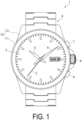
- FIG. 1 is a front view illustrating the watch 1.
- the watch 1 is configured as a wristwatch worn on a user's wrist.
- the watch 1 includes a case 10 made of a metal. Inside the case 10, the watch 1 includes a disc-shaped dial 2, a seconds hand 3, a minute hand 4, an hour hand 5, a crown 6, an A-button 7, and a B-button 8. A band 9 is attached to the case 10.
- the case 10 also includes a case body 11 and bows 12.
- the case body 11 houses therein the dial 2, the seconds hand 3, the minute hand 4, the hour hand 5, and the like described above.
- the bows 12 are provided at the 6 and 12 o'clock positions of the case body 11.
- a band 9 is attached to each of the bows 12 with a spring bar not illustrated in the drawing, or the like.
- dial 2 is an example of the watch component of the present disclosure.
- FIG. 2 is a cross-sectional view illustrating a main part of the dial 2
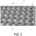
- FIG. 3 is an enlarged cross-sectional view illustrating the main part of the dial 2. Note that FIG. 2 is a perspective view obtained by cutting a substrate 30 in the dial 2 in the thickness direction.
- the dial 2 includes the substrate 30 and a multilayer film 31.
- the substrate 30 is entirely covered with the multilayer film 31. That is, the multilayer film 31 is stacked covering the entirety of a surface 301 of the substrate 30.
- dial 2 is not limited to the above-mentioned configuration, and the multilayer film 31 may be stacked covering a part of the surface 301 of the substrate 30, for example.
- a material of the substrate 30 is composed of metal such as iron, brass, and aluminum, resin, or the like. Note that when the substrate 30 is composed of resin, the resin may be a non-light transmissive resin that does not transmit light, or a light transmissive resin that transmits light.
- a plurality of recesses 32 is formed in the surface 301 of the substrate 30 in the dial 2.
- the plurality of recesses 32 is formed in the surface 301 of the substrate 30. Specifically, the recesses 32 are formed such that a plurality of cone-shaped protrusions is formed at the surface 301 as illustrated in FIG. 3 .
- the depth of each of the recesses 32 along the thickness direction of the substrate 30 is defined as D, and a length between bottom portions 321 of adjacent ones of the adjacent recesses 32 is defined as a pitch P.
- the recesses 32 are formed such that the depth D is 55 ⁇ m or less, the pitch P is 65 ⁇ m or more, or the inclination ⁇ is 70° or less, the pitch P is 65 ⁇ m or more, or the inclination ⁇ is 40° or less, and the depth D is 55 ⁇ m or less. More preferably, the recesses 32 are formed such that the depth D is 40 ⁇ m or less, the pitch P is 75 ⁇ m or more, and the inclination ⁇ is 40° or less.
- the multilayer film 31 is stacked on the substrate 30 on the surface 301 side thereof.
- the multilayer film 31 includes a color absorbing film and a color adjusting film.
- the color absorbing film is stacked on the substrate 30 on the surface 301 side thereof and is formed using a metal.
- a metal such as Ag, Pt, Au, Cu, Al, Cr, Sn, Fe, Ti or the like, an alloy thereof, or the like may be used as the metal forming the color absorbing film.
- a method for forming the color absorbing film is not particularly limited, and examples thereof include ion-assisted deposition, ion plating deposition, vacuum vapor deposition, sputtering, and the like.
- the color adjusting film is a film that adjusts a color tone through optical interference.
- the color adjusting film is composed of a multilayer film including an inorganic film. More specifically, the color adjusting film may be composed of a material including at least one of TazOs, SiO 2 , TiO 2 , Al 2 O 3 , ZrOz, NbzOs, HfOz, Na 5 Al 3 F 14 , Na 3 AlF 6 , AlF 3 , MgF 2 , CaF 2 , BaF 2 , YF 3 , LaF 3 , CeF 3 , or NdF 3 .
- these inorganic substances have high chemical stability, high stability and durability of the external appearance as a watch component can be achieved.
- a method for forming the color adjusting film is not limited, and examples thereof include ion-assisted deposition, ion plating vapor deposition, vacuum deposition, sputtering, and the like. In this manner, the layer configuration of the multilayer film 31 can be freely changed.
- a plurality of the first recesses 32 are formed in the surface 301 of the substrate 30 of the dial 2.
- the recess 32 is formed through processing such as cutting processing, laser processing, chemical removal processing, polishing processing, and forging or casting processing on the surface 301 of the substrate 30.
- the recesses 32 are formed such that the depth D is 55 ⁇ m or less, the pitch P is 65 ⁇ m or more, or the inclination ⁇ is 70° or less, the pitch P is 65 ⁇ m or more, or the inclination ⁇ is 40° or less, and the depth D is 55 ⁇ m or less.
- a plurality of cone-shaped protrusions are formed at the surface 301.
- the multilayer film 31 is stacked at the surface 301 of the substrate 30 of the dial 2.
- the multilayer film 31 is formed by stacking a color absorbing film and a color adjusting film at the surface 301 of the substrate 30 by ion-assisted vapor deposition, ion plating vapor deposition, vacuum vapor deposition, sputtering, or the like. In this manner, the dial 2 can be manufactured.
- the watch 1 can be manufactured by using the dial 2 manufactured by the above-described manufacturing method for the watch 1.
- FIG. 4 is a schematic view illustrating a method for measuring an average value of the brightness L*.
- Table 1 the conditions in Table 1 below, light was emitted onto test pieces S1 to S16 with a substrate in which a plurality of recesses were formed and onto a substrate without the recesses formed, and the average value of the brightness L* of the reflection light was measured.
- the substrate without the recesses formed is referred to as a reference plate.
- the test pieces S1 to S16 and the reference plate are irradiated with light at an angle of 45°. Then, the brightness L* at the position of the viewing angle of -15° to 110° was measured with respect to the position of the regular reflection viewing angle, and the average value of the brightness was obtained. That is, the brightness of the test pieces S1 to S16 and the reference plate as viewed from a wide range of viewing angles was evaluated as the average value of the brightness L*.
- the brightness L* is a brightness value in a L*a*b* color space defined by CIE (Commission Internationale d'Eclairage; International Commission on Illumination).
- CIE Commission Internationale d'Eclairage; International Commission on Illumination.
- Test piece S1 Depth D ( ⁇ m) Pitch P ( ⁇ m) inclination (°) Test piece S1 55 95 66 Test piece S2 55 75 68 Test piece S3 55 55 71 Test piece S4 55 35 76 Test piece S5 40 95 50 Test piece S6 40 75 58 Test piece S7 40 55 66 Test piece S8 40 35 73 Test piece S9 25 95 39 Test piece S10 25 75 36 Test piece S11 25 55 32 Test piece S12 25 35 67 Test piece S13 10 95 15 Test piece S14 10 75 15 Test piece S15 10 55 37 Test piece S16 10 35 49
- FIG. 5 is a diagram illustrating the relationship among the average value of the brightness L* as the evaluation test result, the depth D, and the pitch P.
- the average value of the brightness L* of the reflected light from the reference plate was irradiated with light was 45.
- the average value of the brightness L* of the test pieces S1, S2, S5, S6, S9, S10, S13, S14, and S15 exceeded 45 which is the average value of the brightness L* of the substrate.
- the ratio of the light regularly reflected on the surface is high, and thus the value of the brightness L* at the position of the regular reflection is high, but the value of the brightness L* at other viewing angles is low, and thus the average value of the brightness L* is small.
- the average value of the brightness L* is expected to be higher than that with the reference plate, due to the light radiated on the recesses being appropriately scattered by the side surface of the recesses to be dispersed.
- the plurality of recesses 32 are formed on the substrate 30 such that the depth D is 55 ⁇ m or less, the pitch P is 65 ⁇ m or more, or the inclination ⁇ is 70° or less, the pitch P is 65 ⁇ m or more, or the inclination ⁇ is 40° or less, and the depth D is 55 ⁇ m or less, the incident light is appropriately scattered on the side surface 322 of the recesses 32, whereby the average value of the brightness L* as viewed at a wider range of viewing angles can be made higher than that in a case where the recesses are not formed.
- the decorative and design properties can be enhanced.
- the average value of the brightness L* as viewed at a wide range of viewing angles can be significantly higher than that in a case where the recesses are not formed.
- an even larger variety of brightness can be expressed, and the decorative and design properties can be enhanced.
- the multilayer film 31 includes a color adjusting film made of a material including at least one of TazOs, SiO 2 , TiO 2 , Al 2 O 3 , ZrOz, NbzOs, HfOz, Na 5 Al 3 F 14 , Na 3 AlF 6 , AlF 3 , MgF 2 , CaF 2 , BaF 2 , YF 3 , LaF 3 , CeF 3 , and NdF 3 . Accordingly, it is possible to extend the range of color tones that can be expressed by the dial 2. Further, it is possible to improve the appearance stability and durability of the dial 2 because such inorganic substances have high chemical stability.
- the multilayer film 31 includes the color absorbing film formed using a metal. Accordingly, it is possible to obtain a luxurious appearance with the dial 2.
- the second embodiment differs from the first embodiment described above in that the recesses 32A are defined by the side surface 322A curved.
- FIG. 6 is a cross-sectional view illustrating a dial 2A main part of a second embodiment.
- a plurality of recesses 32A are formed at a surface 301A of a substrate 30A.
- a side surface 322A and a bottom portion 321A of the recess 32A are curved.
- the recess 32A is formed such that a plurality of cone-shaped protrusions is formed at the surface 301A.
- the depth of each of the recesses 32A along the thickness direction of the substrate 30A is defined as D1
- a length between bottom portions 321A of adjacent ones of the adjacent recesses 32A is defined as a pitch P1, as in the first embodiment described above.
- the recesses 32A are formed such that the depth D1 is 55 ⁇ m or less, the pitch P1 is 65 ⁇ m or more, or the inclination ⁇ 1 is 70° or less, the pitch P1 is 65 ⁇ m or more, or the inclination ⁇ 1 is 40° or less, and the depth D1 is 55 ⁇ m or less, as in the first embodiment described above. More preferably, the recesses 32A are formed such that the depth D1 is 40 ⁇ m or less, the pitch P1 is 75 ⁇ m or more, and the inclination ⁇ 1 is 40° or less.
- the side surface 322A and the bottom portion 321A defining the recess 32A are curved. In this manner, since the side defining the recess 32A is not limited to straight lines, greater flexibility in the processing for forming the recess 32A can be achieved.
- the recesses 32 and 32A are formed through any one of cutting processing, laser processing, chemical removal processing, polishing processing, or forging or casting processing, but this is not limitative.
- the recess may be formed through femtolaser processing or picolaser processing. In this manner, the inclination of the side surfaces 322, 322A can be changed with higher accuracy.
- the multilayer film 31 is stacked at the surfaces 301, 301A of the substrate 30, 30A so as to cover at least part thereof, but the present disclosure is not limited thereto.
- the present disclosure includes a configuration where the multilayer film is not stacked at the surface of the substrate.
- the watch component of the present disclosure is configured as the dial 2, but this is not limitative.
- the watch component of the present disclosure may be configured as one of a case, a dial ring, a glass edge, a movement, a handle, an abbreviation, or an oscillating weight.
- a watch component includes a substrate having a surface on which a plurality of recesses are formed, wherein in a cross-sectional view obtained by cutting the substrate in a thickness direction, a depth of the recesses along the thickness direction is 55 ⁇ m or less, and a pitch which is a length between bottom portions of adjacent ones of the recesses is 65 ⁇ m or more.
- the present disclosure by forming a plurality of recesses such that the depth is 55 ⁇ m or less and the pitch is 65 ⁇ m or more, incident light is appropriately scattered on the side surfaces of the recesses.
- an average value of the brightness L* a viewed from a wide range of viewing angles larger than that in a case where the recesses are not formed can be obtained.
- an even larger variety of brightness can be expressed, and the decorative and design properties can be enhanced.
- a watch component includes a substrate having a surface on which a plurality of recesses are formed, wherein in a cross-sectional view obtained by cutting the substrate in a thickness direction, a tangent at a center point of a side surface of each of the recesses is inclined by 70° or less with respect to a direction orthogonal to the thickness direction, and a pitch which is a length between bottom portions of adjacent ones of the recesses is 65 ⁇ m or more.
- the present disclosure by forming a plurality of recesses such that the inclination is 70° or less and the pitch is 65 ⁇ m or more, incident light is appropriately scattered on the side surfaces of the recesses.
- an average value of the brightness L* a viewed from a wide range of viewing angles larger than that in a case where the recesses are not formed can be obtained.
- an even larger variety of brightness can be expressed, and the decorative and design properties can be enhanced.
- a watch component includes a substrate having a surface on which a plurality of recesses are formed, wherein in a cross-sectional view obtained by cutting the substrate in a thickness direction, a tangent at a center point of a side surface of each of the recesses is inclined by 40° or less with respect to a direction orthogonal to the thickness direction, and a depth of the recesses along the thickness direction is 55 ⁇ m or less.
- the depth of the recesses along the thickness direction may be 40 ⁇ m or less
- the pitch which is the length between the bottom portions of adjacent ones of the recesses may be 75 ⁇ m or more
- the tangent at the center point of the side surface of each of the recesses may be inclined by 40° or less with respect to the direction orthogonal to the thickness direction.
- the average value of the brightness L* as viewed at a wide range of viewing angles can be significantly higher than that in a case where the recesses are not formed.
- an even larger variety of brightness can be expressed, and the decorative and design properties can be enhanced.
- the watch component according to the present disclosure may further include a multilayer film configured to cover at least part of the substrate.
- the multilayer film may include a color adjusting film composed of a material including at least one of Ta 2 O 5 , SiO 2 , TiO 2 , Al 2 O 3 , ZrO 2 , Nb 2 O 5 , HfO 2 , Na 5 Al 3 F 14 , Na 3 AlF 6 , AlF 3 , MgF 2 , CaF 2 , BaF 2 , YF 3 , LaF 3 , CeF 3 , or NdF 3 .
- a color adjusting film composed of a material including at least one of Ta 2 O 5 , SiO 2 , TiO 2 , Al 2 O 3 , ZrO 2 , Nb 2 O 5 , HfO 2 , Na 5 Al 3 F 14 , Na 3 AlF 6 , AlF 3 , MgF 2 , CaF 2 , BaF 2 , YF 3 , LaF 3 , CeF 3 , or NdF 3 .
- the multilayer film may include a color absorbing film formed using a metal.
- a watch of the present disclosure includes the watch component described above.
- a method for manufacturing a watch component according to the present disclosure is a method for manufacturing a watch component including a substrate, the method including forming a plurality of recesses on a surface of the substrate, wherein in a cross-sectional view obtained by cutting the substrate in a thickness direction, a depth of the recesses along the thickness direction is 55 ⁇ m or less, and a pitch which is a length between bottom portions of adjacent ones of the recesses is 65 ⁇ m or more.
- a method for manufacturing a watch component according to the present disclosure is a method for manufacturing a watch component including a substrate, the method including forming a plurality of recesses on a surface of the substrate, wherein in a cross-sectional view obtained by cutting the substrate in a thickness direction, a tangent at a center point of a side surface of each of the recesses is inclined by 70° or less with respect to a direction orthogonal to the thickness direction, and a pitch which is a length between bottom portions of adjacent ones of the recesses is 65 ⁇ m or more.
- a method for manufacturing a watch component according to the present disclosure is a method for manufacturing a watch component including a substrate, the method including forming a plurality of recesses on a surface of the substrate, wherein in a cross-sectional view obtained by cutting the substrate in a thickness direction, a tangent at a center point of a side surface of each of the recesses is inclined by 40° or less with respect to a direction orthogonal to the thickness direction, and a depth of the recesses along the thickness direction is 55 ⁇ m or less.
Landscapes
- Physics & Mathematics (AREA)
- Optics & Photonics (AREA)
- Engineering & Computer Science (AREA)
- General Physics & Mathematics (AREA)
- Plasma & Fusion (AREA)
- Mechanical Engineering (AREA)
- Health & Medical Sciences (AREA)
- General Health & Medical Sciences (AREA)
- Toxicology (AREA)
- Laminated Bodies (AREA)
- Physical Vapour Deposition (AREA)
Abstract
A watch component includes a substrate having a surface on which a plurality of recesses are formed, wherein in a cross-sectional view obtained by cutting the substrate in a thickness direction, a depth of the recesses along the thickness direction is 55 µm or less, and a pitch which is a length between bottom portions of adjacent ones of the recesses is 65 µm or more.
Description
- The present disclosure relates to a watch component, a watch, and a method for manufacturing the watch component.
-
JP-A-2022-11407 JP-A-2022-11407 - According to
JP-A-2022-11407 - A watch component according to the present disclosure includes a substrate having a surface on which a plurality of recesses are formed, wherein in a cross-sectional view obtained by cutting the substrate in a thickness direction, a depth of the recesses along the thickness direction is 55 µm or less, and a pitch which is a length between bottom portions of adjacent ones of the recesses is 65 µm or more.
- A watch component according to the present disclosure includes a substrate having a surface on which a plurality of recesses are formed, wherein in a cross-sectional view obtained by cutting the substrate in a thickness direction, a tangent at a center point of a side surface of each of the recesses is inclined by 70° or less with respect to a direction orthogonal to the thickness direction, and a pitch which is a length between bottom portions of adjacent ones of the recesses is 65 µm or more.
- A watch component according to the present disclosure includes a substrate having a surface on which a plurality of recesses are formed, wherein in a cross-sectional view obtained by cutting the substrate in a thickness direction, a tangent at a center point of a side surface of each of the recesses is inclined by 40° or less with respect to a direction orthogonal to the thickness direction, and a depth of the recesses along the thickness direction is 55 µm or less.
- A watch of the present disclosure includes the watch component described above.
- A method for manufacturing a watch component according to the present disclosure is a method for manufacturing a watch component including a substrate, the method including forming a plurality of recesses on a surface of the substrate, wherein in a cross-sectional view obtained by cutting the substrate in a thickness direction, a depth of the recesses along the thickness direction is 55 µm or less, and a pitch which is a length between bottom portions of adjacent ones of the recesses is 65 µm or more.
- A method for manufacturing a watch component according to the present disclosure is a method for manufacturing a watch component including a substrate, the method including forming a plurality of recesses on a surface of the substrate, wherein in a cross-sectional view obtained by cutting the substrate in a thickness direction, a tangent at a center point of a side surface of each of the recesses is inclined by 70° or less with respect to a direction orthogonal to the thickness direction, and a pitch which is a length between bottom portions of adjacent ones of the recesses is 65 µm or more.
- A method for manufacturing a watch component according to the present disclosure is a method for manufacturing a watch component including a substrate, the method including forming a plurality of recesses on a surface of the substrate, wherein in a cross-sectional view obtained by cutting the substrate in a thickness direction, a tangent at a center point of a side surface of each of the recesses is inclined by 40° or less with respect to a direction orthogonal to the thickness direction, and a depth of the recesses along the thickness direction is 55 µm or less.
-
-
FIG. 1 is a front view illustrating a watch of a first embodiment. -
FIG. 2 is a cross-sectional view illustrating a dial main part of a first embodiment. -
FIG. 3 is an enlarged perspective view illustrating a main part of the dial of the first embodiment. -
FIG. 4 is a schematic view illustrating a method for measuring an average value of brightness L*. -
FIG. 5 is a diagram illustrating a relationship among the average value of the brightness L*, a depth D, and a pitch P. -
FIG. 6 is a cross-sectional view illustrating a dial main part of a second embodiment. - A
watch 1 according to an embodiment of the present disclosure will be described below with reference to the drawings. -
FIG. 1 is a front view illustrating thewatch 1. In this embodiment, thewatch 1 is configured as a wristwatch worn on a user's wrist. - As illustrated in
FIG. 1 , thewatch 1 includes acase 10 made of a metal. Inside thecase 10, thewatch 1 includes a disc-shaped dial 2, aseconds hand 3, aminute hand 4, anhour hand 5, acrown 6, anA-button 7, and a B-button 8. Aband 9 is attached to thecase 10. - The
case 10 also includes a case body 11 andbows 12. The case body 11 houses therein thedial 2, theseconds hand 3, theminute hand 4, thehour hand 5, and the like described above. Thebows 12 are provided at the 6 and 12 o'clock positions of the case body 11. Aband 9 is attached to each of thebows 12 with a spring bar not illustrated in the drawing, or the like. - Note that the
dial 2 is an example of the watch component of the present disclosure. -
FIG. 2 is a cross-sectional view illustrating a main part of thedial 2, andFIG. 3 is an enlarged cross-sectional view illustrating the main part of thedial 2. Note thatFIG. 2 is a perspective view obtained by cutting asubstrate 30 in thedial 2 in the thickness direction. - As illustrated in
FIGS. 2 and3 , thedial 2 includes thesubstrate 30 and amultilayer film 31. In this embodiment, thesubstrate 30 is entirely covered with themultilayer film 31. That is, themultilayer film 31 is stacked covering the entirety of asurface 301 of thesubstrate 30. - Note that the
dial 2 is not limited to the above-mentioned configuration, and themultilayer film 31 may be stacked covering a part of thesurface 301 of thesubstrate 30, for example. - A material of the
substrate 30 is composed of metal such as iron, brass, and aluminum, resin, or the like. Note that when thesubstrate 30 is composed of resin, the resin may be a non-light transmissive resin that does not transmit light, or a light transmissive resin that transmits light. - In this embodiment, a plurality of
recesses 32 is formed in thesurface 301 of thesubstrate 30 in thedial 2. - In this embodiment, the plurality of
recesses 32 is formed in thesurface 301 of thesubstrate 30. Specifically, therecesses 32 are formed such that a plurality of cone-shaped protrusions is formed at thesurface 301 as illustrated inFIG. 3 . - In this embodiment, the depth of each of the
recesses 32 along the thickness direction of thesubstrate 30 is defined as D, and a length betweenbottom portions 321 of adjacent ones of theadjacent recesses 32 is defined as a pitch P. Inclination θ of a tangent T at amiddle point 323 of aside surface 322 of each of therecesses 32 with respect to a direction orthogonal to the thickness direction. - Under this condition, in this embodiment, the
recesses 32 are formed such that the depth D is 55 µm or less, the pitch P is 65 µm or more, or the inclination θ is 70° or less, the pitch P is 65 µm or more, or the inclination θ is 40° or less, and the depth D is 55 µm or less. More preferably, therecesses 32 are formed such that the depth D is 40 µm or less, the pitch P is 75 µm or more, and the inclination θ is 40° or less. - The
multilayer film 31 is stacked on thesubstrate 30 on thesurface 301 side thereof. In this embodiment, themultilayer film 31 includes a color absorbing film and a color adjusting film. - The color absorbing film is stacked on the
substrate 30 on thesurface 301 side thereof and is formed using a metal. Note that Ag, Pt, Au, Cu, Al, Cr, Sn, Fe, Ti or the like, an alloy thereof, or the like may be used as the metal forming the color absorbing film. - A method for forming the color absorbing film is not particularly limited, and examples thereof include ion-assisted deposition, ion plating deposition, vacuum vapor deposition, sputtering, and the like.
- The color adjusting film is a film that adjusts a color tone through optical interference. In this embodiment, the color adjusting film is composed of a multilayer film including an inorganic film. More specifically, the color adjusting film may be composed of a material including at least one of TazOs, SiO2, TiO2, Al2O3, ZrOz, NbzOs, HfOz, Na5Al3F14, Na3AlF6, AlF3, MgF2, CaF2, BaF2, YF3, LaF3, CeF3, or NdF3. In this manner, since these inorganic substances have high chemical stability, high stability and durability of the external appearance as a watch component can be achieved.
- Note that a method for forming the color adjusting film is not limited, and examples thereof include ion-assisted deposition, ion plating vapor deposition, vacuum deposition, sputtering, and the like. In this manner, the layer configuration of the
multilayer film 31 can be freely changed. - Next, a method for manufacturing the
dial 2 is described. - First, a plurality of the
first recesses 32 are formed in thesurface 301 of thesubstrate 30 of thedial 2. For example, therecess 32 is formed through processing such as cutting processing, laser processing, chemical removal processing, polishing processing, and forging or casting processing on thesurface 301 of thesubstrate 30. In this process, therecesses 32 are formed such that the depth D is 55 µm or less, the pitch P is 65 µm or more, or the inclination θ is 70° or less, the pitch P is 65 µm or more, or the inclination θ is 40° or less, and the depth D is 55 µm or less. Thus, a plurality of cone-shaped protrusions are formed at thesurface 301. - Next, the
multilayer film 31 is stacked at thesurface 301 of thesubstrate 30 of thedial 2. Specifically, themultilayer film 31 is formed by stacking a color absorbing film and a color adjusting film at thesurface 301 of thesubstrate 30 by ion-assisted vapor deposition, ion plating vapor deposition, vacuum vapor deposition, sputtering, or the like. In this manner, thedial 2 can be manufactured. - Further, the
watch 1 can be manufactured by using thedial 2 manufactured by the above-described manufacturing method for thewatch 1. - Next, in this embodiment, the results of measuring the brightness L* of reflected light obtained by irradiating a test piece with a plurality of recesses formed in a metal substrate and a substrate without the recesses formed, with light will be described in detail.
-
FIG. 4 is a schematic view illustrating a method for measuring an average value of the brightness L*. As illustrated inFIG. 4 , under the conditions in Table 1 below, light was emitted onto test pieces S1 to S16 with a substrate in which a plurality of recesses were formed and onto a substrate without the recesses formed, and the average value of the brightness L* of the reflection light was measured. Hereinafter, the substrate without the recesses formed is referred to as a reference plate. - As a specific evaluation test method, the test pieces S1 to S16 and the reference plate are irradiated with light at an angle of 45°. Then, the brightness L* at the position of the viewing angle of -15° to 110° was measured with respect to the position of the regular reflection viewing angle, and the average value of the brightness was obtained. That is, the brightness of the test pieces S1 to S16 and the reference plate as viewed from a wide range of viewing angles was evaluated as the average value of the brightness L*.
- Note that in the present disclosure, the brightness L* is a brightness value in a L*a*b* color space defined by CIE (Commission Internationale d'Eclairage; International Commission on Illumination). When the value of L* is "0", it is the brightness of an object that reflects no light (completely absorbs the light). When the value of L* is "100", it is a value of the brightness of white that totally reflects light.
[Table 1] Depth D (µm) Pitch P (µm) inclination (°) Test piece S1 55 95 66 Test piece S2 55 75 68 Test piece S3 55 55 71 Test piece S4 55 35 76 Test piece S5 40 95 50 Test piece S6 40 75 58 Test piece S7 40 55 66 Test piece S8 40 35 73 Test piece S9 25 95 39 Test piece S10 25 75 36 Test piece S11 25 55 32 Test piece S12 25 35 67 Test piece S13 10 95 15 Test piece S14 10 75 15 Test piece S15 10 55 37 Test piece S16 10 35 49 -
FIG. 5 is a diagram illustrating the relationship among the average value of the brightness L* as the evaluation test result, the depth D, and the pitch P. - As illustrated in
FIG. 5 , the average value of the brightness L* of the reflected light from the reference plate was irradiated with light was 45. On the other hand, the average value of the brightness L* of the test pieces S1, S2, S5, S6, S9, S10, S13, S14, and S15 exceeded 45 which is the average value of the brightness L* of the substrate. - This is because, with the reference plate, the ratio of the light regularly reflected on the surface is high, and thus the value of the brightness L* at the position of the regular reflection is high, but the value of the brightness L* at other viewing angles is low, and thus the average value of the brightness L* is small. On the other hand, with the test pieces S1, S2, S5, S6, S9, S10, S13, S14, and S15, the average value of the brightness L* is expected to be higher than that with the reference plate, due to the light radiated on the recesses being appropriately scattered by the side surface of the recesses to be dispersed.
- This indicates that with the plurality of
recesses 32 formed on the substrate such that the depth D is 55 µm or less, the pitch P is 65 µm or more, or the inclination θ is 70° or less, the pitch P is 65 µm or more, or the inclination θ is 40° or less, and the depth D is 55 µm or less, an average value of the brightness L* can be made higher than that obtained with the reference plate. In particular, it was suggested that with the test pieces S9, S10, S13, and S14 in which the depth D was 40 µm or less, the pitch P was 75 µm or more, and the inclination θ was 40° or less, a significantly high average value of the brightness L* of about 70 was obtained. - According to this embodiment, the following effects can be achieved.
- In this embodiment, the plurality of
recesses 32 are formed on thesubstrate 30 such that the depth D is 55 µm or less, the pitch P is 65 µm or more, or the inclination θ is 70° or less, the pitch P is 65 µm or more, or the inclination θ is 40° or less, and the depth D is 55 µm or less, the incident light is appropriately scattered on theside surface 322 of therecesses 32, whereby the average value of the brightness L* as viewed at a wider range of viewing angles can be made higher than that in a case where the recesses are not formed. Thus, an even larger variety of brightness can be expressed, and the decorative and design properties can be enhanced. - In this embodiment, with the
recesses 32 formed such that the depth D is 40 µm or less, the pitch P is 75 µm or more, and the inclination θ of the tangent is 40° or less, the average value of the brightness L* as viewed at a wide range of viewing angles can be significantly higher than that in a case where the recesses are not formed. Thus, an even larger variety of brightness can be expressed, and the decorative and design properties can be enhanced. - In this embodiment, since at least part of the
substrate 30 is covered with themultilayer film 31, various color tones can be expressed in addition to brightness, whereby decorative and design properties can be enhanced. - In this embodiment, the
multilayer film 31 includes a color adjusting film made of a material including at least one of TazOs, SiO2, TiO2, Al2O3, ZrOz, NbzOs, HfOz, Na5Al3F14, Na3AlF6, AlF3, MgF2, CaF2, BaF2, YF3, LaF3, CeF3, and NdF3. Accordingly, it is possible to extend the range of color tones that can be expressed by thedial 2. Further, it is possible to improve the appearance stability and durability of thedial 2 because such inorganic substances have high chemical stability. - In this embodiment, the
multilayer film 31 includes the color absorbing film formed using a metal. Accordingly, it is possible to obtain a luxurious appearance with thedial 2. - Next, a second embodiment of the present disclosure is described with reference to
FIG. 6 . The second embodiment differs from the first embodiment described above in that therecesses 32A are defined by theside surface 322A curved. - Note that in the second embodiment, components the same as or similar to those of the first embodiment are denoted with the same reference numerals, and the description will be omitted or simplified.
-
FIG. 6 is a cross-sectional view illustrating adial 2A main part of a second embodiment. As in the first embodiment described above, in this embodiment, a plurality ofrecesses 32A are formed at asurface 301A of asubstrate 30A. In this embodiment, aside surface 322A and abottom portion 321A of therecess 32A are curved. - In addition, as in the above-described first embodiment, the
recess 32A is formed such that a plurality of cone-shaped protrusions is formed at thesurface 301A. - In this embodiment, the depth of each of the
recesses 32A along the thickness direction of thesubstrate 30A is defined as D1, and a length betweenbottom portions 321A of adjacent ones of theadjacent recesses 32A is defined as a pitch P1, as in the first embodiment described above. Inclination θ of a tangent T1 at amiddle point 323A of aside surface 322A of each of therecesses 32A with respect to a direction orthogonal to the thickness direction. - Under this condition, in this embodiment, the
recesses 32A are formed such that the depth D1 is 55 µm or less, the pitch P1 is 65 µm or more, or the inclination θ1 is 70° or less, the pitch P1 is 65 µm or more, or the inclination θ1 is 40° or less, and the depth D1 is 55 µm or less, as in the first embodiment described above. More preferably, therecesses 32A are formed such that the depth D1 is 40 µm or less, the pitch P1 is 75 µm or more, and the inclination θ1 is 40° or less. - According to this embodiment, the following effects can be achieved.
- In this embodiment, the
side surface 322A and thebottom portion 321A defining therecess 32A are curved. In this manner, since the side defining therecess 32A is not limited to straight lines, greater flexibility in the processing for forming therecess 32A can be achieved. - Note that the present disclosure is not limited to the above-described embodiments, and modification, change, and the like can be performed in so far as the advantages of the present disclosure can be achieved.
- In the above-described each embodiment, the
recesses - In each of the above-described embodiments, the
multilayer film 31 is stacked at thesurfaces substrate - In the above-described embodiments, the watch component of the present disclosure is configured as the
dial 2, but this is not limitative. For example, the watch component of the present disclosure may be configured as one of a case, a dial ring, a glass edge, a movement, a handle, an abbreviation, or an oscillating weight. - A watch component according to the present disclosure includes a substrate having a surface on which a plurality of recesses are formed, wherein in a cross-sectional view obtained by cutting the substrate in a thickness direction, a depth of the recesses along the thickness direction is 55 µm or less, and a pitch which is a length between bottom portions of adjacent ones of the recesses is 65 µm or more.
- In the present disclosure, by forming a plurality of recesses such that the depth is 55 µm or less and the pitch is 65 µm or more, incident light is appropriately scattered on the side surfaces of the recesses. Thus, an average value of the brightness L* a viewed from a wide range of viewing angles larger than that in a case where the recesses are not formed can be obtained. Thus, an even larger variety of brightness can be expressed, and the decorative and design properties can be enhanced.
- A watch component according to the present disclosure includes a substrate having a surface on which a plurality of recesses are formed, wherein in a cross-sectional view obtained by cutting the substrate in a thickness direction, a tangent at a center point of a side surface of each of the recesses is inclined by 70° or less with respect to a direction orthogonal to the thickness direction, and a pitch which is a length between bottom portions of adjacent ones of the recesses is 65 µm or more.
- In the present disclosure, by forming a plurality of recesses such that the inclination is 70° or less and the pitch is 65 µm or more, incident light is appropriately scattered on the side surfaces of the recesses. Thus, an average value of the brightness L* a viewed from a wide range of viewing angles larger than that in a case where the recesses are not formed can be obtained. Thus, an even larger variety of brightness can be expressed, and the decorative and design properties can be enhanced.
- A watch component according to the present disclosure includes a substrate having a surface on which a plurality of recesses are formed, wherein in a cross-sectional view obtained by cutting the substrate in a thickness direction, a tangent at a center point of a side surface of each of the recesses is inclined by 40° or less with respect to a direction orthogonal to the thickness direction, and a depth of the recesses along the thickness direction is 55 µm or less.
- In the present disclosure, by forming a plurality of recesses such that the inclination is 40° or less and the depth is 55 µm or less, incident light is appropriately scattered on the side surfaces of the recesses. Thus, an average value of the brightness L* a viewed from a wide range of viewing angles larger than that in a case where the recesses are not formed can be obtained. Thus, an even larger variety of brightness can be expressed, and the decorative and design properties can be enhanced.
- In the watch component according to the present disclosure, in the cross-sectional view obtained by cutting the substrate in the thickness direction, the depth of the recesses along the thickness direction may be 40 µm or less, the pitch which is the length between the bottom portions of adjacent ones of the recesses may be 75 µm or more, and the tangent at the center point of the side surface of each of the recesses may be inclined by 40° or less with respect to the direction orthogonal to the thickness direction.
- Thus, with the recesses formed such that the depth is 40 µm or less, the pitch is 75 µm or more, and the inclination of the tangent is 40° or less, the average value of the brightness L* as viewed at a wide range of viewing angles can be significantly higher than that in a case where the recesses are not formed. Thus, an even larger variety of brightness can be expressed, and the decorative and design properties can be enhanced.
- The watch component according to the present disclosure may further include a multilayer film configured to cover at least part of the substrate.
- Thus, since at least part of the substrate is covered with the multilayer film, various color tones can be expressed in addition to brightness, whereby decorative and design properties can be enhanced.
- In the watch component of the present disclosure, the multilayer film may include a color adjusting film composed of a material including at least one of Ta2O5, SiO2, TiO2, Al2O3, ZrO2, Nb2O5, HfO2, Na5Al3F14, Na3AlF6, AlF3, MgF2, CaF2, BaF2, YF3, LaF3, CeF3, or NdF3.
- Accordingly, it is possible to extend the range of color tones that can be expressed by the watch component. Further, it is possible to improve the appearance stability and durability of the watch component because such inorganic substances have high chemical stability.
- In the watch component of the present disclosure, the multilayer film may include a color absorbing film formed using a metal.
- In this manner, a luxurious appearance as a watch component can be achieved.
- A watch of the present disclosure includes the watch component described above.
- A method for manufacturing a watch component according to the present disclosure is a method for manufacturing a watch component including a substrate, the method including forming a plurality of recesses on a surface of the substrate, wherein in a cross-sectional view obtained by cutting the substrate in a thickness direction, a depth of the recesses along the thickness direction is 55 µm or less, and a pitch which is a length between bottom portions of adjacent ones of the recesses is 65 µm or more.
- Thus, by forming a plurality of recesses such that the depth is 55 µm or less and the pitch is 65 µm or more, incident light is appropriately scattered on the side surfaces of the recesses. Thus, an average value of the brightness L* a viewed from a wide range of viewing angles larger than that in a case where the recesses are not formed can be obtained. Thus, an even larger variety of brightness can be expressed, and the decorative and design properties can be enhanced.
- A method for manufacturing a watch component according to the present disclosure is a method for manufacturing a watch component including a substrate, the method including forming a plurality of recesses on a surface of the substrate, wherein in a cross-sectional view obtained by cutting the substrate in a thickness direction, a tangent at a center point of a side surface of each of the recesses is inclined by 70° or less with respect to a direction orthogonal to the thickness direction, and a pitch which is a length between bottom portions of adjacent ones of the recesses is 65 µm or more.
- Thus, by forming a plurality of recesses such that the inclination is 70° or less and the pitch is 65 µm or more, incident light is appropriately scattered on the side surfaces of the recesses. Thus, an average value of the brightness L* a viewed from a wide range of viewing angles larger than that in a case where the recesses are not formed can be obtained. Thus, an even larger variety of brightness can be expressed, and the decorative and design properties can be enhanced.
- A method for manufacturing a watch component according to the present disclosure is a method for manufacturing a watch component including a substrate, the method including forming a plurality of recesses on a surface of the substrate, wherein in a cross-sectional view obtained by cutting the substrate in a thickness direction, a tangent at a center point of a side surface of each of the recesses is inclined by 40° or less with respect to a direction orthogonal to the thickness direction, and a depth of the recesses along the thickness direction is 55 µm or less.
- Thus, by forming a plurality of recesses such that the inclination is 40° or less and the depth is 55 µm or less, incident light is appropriately scattered on the side surfaces of the recesses. Thus, an average value of the brightness L* a viewed from a wide range of viewing angles larger than that in a case where the recesses are not formed can be obtained. Thus, an even larger variety of brightness can be expressed, and the decorative and design properties can be enhanced.
Claims (11)
- A watch component, comprising a substrate having a surface on which a plurality of recesses are formed, whereinin a cross-sectional view obtained by cutting the substrate in a thickness direction, a depth of the recesses along the thickness direction is 55 µm or less, anda pitch which is a length between bottom portions of adjacent ones of the recesses is 65 µm or more.
- A watch component, comprising a substrate having a surface on which a plurality of recesses are formed, whereinin a cross-sectional view obtained by cutting the substrate in a thickness direction, a tangent at a center point of a side surface of the recesses is inclined by 70° or less with respect to a direction orthogonal to the thickness direction, anda pitch which is a length between bottom portions of adjacent ones of the recesses is 65 µm or more.
- A watch component, comprising a substrate having a surface on which a plurality of recesses are formed, whereinin a cross-sectional view obtained by cutting the substrate in a thickness direction, a tangent at a center point of a side surface of the recesses is inclined by 40° or less with respect to a direction orthogonal to the thickness direction, anda depth of the recesses along the thickness direction is 55 µm or less.
- The watch component according to claim 1, whereinin the cross-sectional view obtained by cutting the substrate in the thickness direction, the depth of the recesses along the thickness direction is 40 µm or less,the pitch which is the length between the bottom portions of adjacent ones of the recesses is 75 µm or more, andthe tangent at the center point of the side surface of the recesses is inclined by 40° or less with respect to the direction orthogonal to the thickness direction.
- The watch component according to claim 1 comprising a multilayer film configured to cover at least part of the substrate.
- The watch component according to claim 5, wherein
the multilayer film includes a color adjusting film composed of a material including at least one of Ta2O5, SiO2, TiO2, Al2O3, ZrO2, Nb2O5, HfO2, Na5Al3F14, Na3AlF6, AlF3, MgF2, CaF2, BaF2, YF3, LaF3, CeF3, or NdF3. - The watch component according to claim 5, wherein the multilayer film includes a color absorbing film formed using a metal.
- A watch comprising the watch component according to claim 1.
- A method for manufacturing a watch component including a substrate, the method comprising forming a plurality of recesses on a surface of the substrate, whereinin a cross-sectional view obtained by cutting the substrate in a thickness direction, a depth of the recesses along the thickness direction is 55 µm or less, anda pitch which is a length between bottom portions of adjacent ones of the recesses is 65 µm or more.
- A method for manufacturing a watch component including a substrate, the method comprising forming a plurality of recesses on a surface of the substrate, whereinin a cross-sectional view obtained by cutting the substrate in a thickness direction, a tangent at a center point of a side surface of the recesses is inclined by 70° or less with respect to a direction orthogonal to the thickness direction, anda pitch which is a length between bottom portions of adjacent ones of the recesses is 65 µm or more.
- A method for manufacturing a watch component including a substrate, the method comprising forming a plurality of recesses on a surface of the substrate, whereinin a cross-sectional view obtained by cutting the substrate in a thickness direction, a tangent at a center point of a side surface of the recesses is inclined by 40° or less with respect to a direction orthogonal to the thickness direction, anda depth of the recesses along the thickness direction is 55 µm or less.
Applications Claiming Priority (1)
| Application Number | Priority Date | Filing Date | Title |
|---|---|---|---|
| JP2023033632A JP2024125663A (en) | 2023-03-06 | 2023-03-06 | Watch component, watch, and method for manufacturing watch component |
Publications (1)
| Publication Number | Publication Date |
|---|---|
| EP4428629A1 true EP4428629A1 (en) | 2024-09-11 |
Family
ID=90361233
Family Applications (1)
| Application Number | Title | Priority Date | Filing Date |
|---|---|---|---|
| EP24161117.7A Pending EP4428629A1 (en) | 2023-03-06 | 2024-03-04 | Watch component, watch, and method for manufacturing watch component |
Country Status (3)
| Country | Link |
|---|---|
| EP (1) | EP4428629A1 (en) |
| JP (1) | JP2024125663A (en) |
| CN (1) | CN118605104A (en) |
Citations (6)
| Publication number | Priority date | Publication date | Assignee | Title |
|---|---|---|---|---|
| JP2005189019A (en) * | 2003-12-25 | 2005-07-14 | Kawaguchiko Seimitsu Co Ltd | Dial plate equipped with solar cell for watch and watch equipped with the same |
| US20090129210A1 (en) * | 2005-02-09 | 2009-05-21 | Citizen Holdings Co., Ltd. | Display Plate for Solar Cell Apparatus and Method of Producing Display Plate for Solar Cell Apparatus |
| US20120155225A1 (en) * | 2010-12-20 | 2012-06-21 | Seiko Epson Corporation | Timepiece faceplate and timepiece |
| JP5414363B2 (en) * | 2009-05-28 | 2014-02-12 | シチズン時計株式会社 | Display board |
| EP3896192A1 (en) * | 2020-04-16 | 2021-10-20 | Richemont International S.A. | Timepiece component with an improved interferential optical system comprising a zinc-based layer |
| US20210402513A1 (en) * | 2020-06-30 | 2021-12-30 | Seiko Epson Corporation | Method for Decorating Watch Component, Watch Component, Watch Movement, and Watch |
-
2023
- 2023-03-06 JP JP2023033632A patent/JP2024125663A/en active Pending
-
2024
- 2024-03-04 EP EP24161117.7A patent/EP4428629A1/en active Pending
- 2024-03-04 CN CN202410240264.8A patent/CN118605104A/en active Pending
Patent Citations (7)
| Publication number | Priority date | Publication date | Assignee | Title |
|---|---|---|---|---|
| JP2005189019A (en) * | 2003-12-25 | 2005-07-14 | Kawaguchiko Seimitsu Co Ltd | Dial plate equipped with solar cell for watch and watch equipped with the same |
| US20090129210A1 (en) * | 2005-02-09 | 2009-05-21 | Citizen Holdings Co., Ltd. | Display Plate for Solar Cell Apparatus and Method of Producing Display Plate for Solar Cell Apparatus |
| JP5414363B2 (en) * | 2009-05-28 | 2014-02-12 | シチズン時計株式会社 | Display board |
| US20120155225A1 (en) * | 2010-12-20 | 2012-06-21 | Seiko Epson Corporation | Timepiece faceplate and timepiece |
| EP3896192A1 (en) * | 2020-04-16 | 2021-10-20 | Richemont International S.A. | Timepiece component with an improved interferential optical system comprising a zinc-based layer |
| US20210402513A1 (en) * | 2020-06-30 | 2021-12-30 | Seiko Epson Corporation | Method for Decorating Watch Component, Watch Component, Watch Movement, and Watch |
| JP2022011407A (en) | 2020-06-30 | 2022-01-17 | セイコーエプソン株式会社 | Decorating method for component for watch, component for watch, movement for watch, and watch |
Also Published As
| Publication number | Publication date |
|---|---|
| CN118605104A (en) | 2024-09-06 |
| JP2024125663A (en) | 2024-09-19 |
Similar Documents
| Publication | Publication Date | Title |
|---|---|---|
| EP1274660B1 (en) | Method for applying an antireflection coating to inorganic optically transparent substrates | |
| US20240111251A1 (en) | Watch Component, Watch, And Method For Manufacturing Watch Component | |
| US12529998B2 (en) | Watch component, watch, and method for manufacturing watch component | |
| KR20000023795A (en) | Plastic optical devices having antireflection film and mechanism for equalizing thickness of antireflection film | |
| JP7115614B2 (en) | Watch parts and watches | |
| US20180181071A1 (en) | Mother-of-pearl substrate coated with a yellow layer | |
| US3176575A (en) | Low reflectance optical member coatings with barrier layer | |
| CN121850399A (en) | Glass plate with dielectric multilayer film and its manufacturing method | |
| US20170299887A1 (en) | Composite High Index Layers for Anti Reflective Stacks | |
| JP4619166B2 (en) | Windshield glass for watches | |
| US20240241479A1 (en) | Watch Dial And Watch | |
| US20240142914A1 (en) | Watch Component, Watch, And Method For Manufacturing Watch Component | |
| US20230315018A1 (en) | Watch Part, Watch, And Method For Manufacturing Watch Part | |
| JP2017181146A (en) | Translucent member, timepiece, and method of manufacturing translucent member | |
| US20230315019A1 (en) | Watch Component, Watch, And Manufacturing Method For Watch Component | |
| US20220299689A1 (en) | External part for a timepiece or a piece of jewellery comprising an interferential colour coating and manufacturing method of said part | |
| AU774079B2 (en) | Plastic optical devices having antireflection film and mechanism for equalizing thickness of antireflection film | |
| CN119179253A (en) | Timepiece component and timepiece | |
| CN118605104A (en) | Timepiece component, timepiece, and method for manufacturing timepiece component | |
| CN118605105A (en) | Substrate, watch component, mold, molded product, and method for producing substrate | |
| CN116804845A (en) | Timepiece component, timepiece movement, and timepiece | |
| EP0093921B1 (en) | Polygonal mirror and method of manufacturing the same | |
| JP7752197B2 (en) | Exterior part made of ceramic material including a protective layer and method for manufacturing such an exterior part - Patent Application 20070122997 | |
| US20250327166A1 (en) | Coating for a substrate; substrate; and article | |
| WO2026037860A1 (en) | Black decorative element for watchmaking or jewelry |
Legal Events
| Date | Code | Title | Description |
|---|---|---|---|
| PUAI | Public reference made under article 153(3) epc to a published international application that has entered the european phase |
Free format text: ORIGINAL CODE: 0009012 |
|
| STAA | Information on the status of an ep patent application or granted ep patent |
Free format text: STATUS: THE APPLICATION HAS BEEN PUBLISHED |
|
| AK | Designated contracting states |
Kind code of ref document: A1 Designated state(s): AL AT BE BG CH CY CZ DE DK EE ES FI FR GB GR HR HU IE IS IT LI LT LU LV MC ME MK MT NL NO PL PT RO RS SE SI SK SM TR |
|
| STAA | Information on the status of an ep patent application or granted ep patent |
Free format text: STATUS: REQUEST FOR EXAMINATION WAS MADE |
|
| 17P | Request for examination filed |
Effective date: 20250213 |