EP4428562A1 - Method for determining a position of a transmitter, and system - Google Patents
Method for determining a position of a transmitter, and system Download PDFInfo
- Publication number
- EP4428562A1 EP4428562A1 EP24155660.4A EP24155660A EP4428562A1 EP 4428562 A1 EP4428562 A1 EP 4428562A1 EP 24155660 A EP24155660 A EP 24155660A EP 4428562 A1 EP4428562 A1 EP 4428562A1
- Authority
- EP
- European Patent Office
- Prior art keywords
- multiplicity
- receivers
- measurement
- transmitter
- control unit
- Prior art date
- Legal status (The legal status is an assumption and is not a legal conclusion. Google has not performed a legal analysis and makes no representation as to the accuracy of the status listed.)
- Pending
Links
- 238000000034 method Methods 0.000 title claims abstract description 30
- 238000005259 measurement Methods 0.000 claims abstract description 62
- 238000004891 communication Methods 0.000 description 5
- 230000001360 synchronised effect Effects 0.000 description 4
- 238000011161 development Methods 0.000 description 2
- 238000010586 diagram Methods 0.000 description 2
- 238000013461 design Methods 0.000 description 1
Images

Classifications
-
- G—PHYSICS
- G01—MEASURING; TESTING
- G01S—RADIO DIRECTION-FINDING; RADIO NAVIGATION; DETERMINING DISTANCE OR VELOCITY BY USE OF RADIO WAVES; LOCATING OR PRESENCE-DETECTING BY USE OF THE REFLECTION OR RERADIATION OF RADIO WAVES; ANALOGOUS ARRANGEMENTS USING OTHER WAVES
- G01S5/00—Position-fixing by co-ordinating two or more direction or position line determinations; Position-fixing by co-ordinating two or more distance determinations
- G01S5/02—Position-fixing by co-ordinating two or more direction or position line determinations; Position-fixing by co-ordinating two or more distance determinations using radio waves
- G01S5/0205—Details
- G01S5/0221—Receivers
- G01S5/02213—Receivers arranged in a network for determining the position of a transmitter
-
- G—PHYSICS
- G01—MEASURING; TESTING
- G01S—RADIO DIRECTION-FINDING; RADIO NAVIGATION; DETERMINING DISTANCE OR VELOCITY BY USE OF RADIO WAVES; LOCATING OR PRESENCE-DETECTING BY USE OF THE REFLECTION OR RERADIATION OF RADIO WAVES; ANALOGOUS ARRANGEMENTS USING OTHER WAVES
- G01S5/00—Position-fixing by co-ordinating two or more direction or position line determinations; Position-fixing by co-ordinating two or more distance determinations
- G01S5/02—Position-fixing by co-ordinating two or more direction or position line determinations; Position-fixing by co-ordinating two or more distance determinations using radio waves
- G01S5/14—Determining absolute distances from a plurality of spaced points of known location
-
- G—PHYSICS
- G01—MEASURING; TESTING
- G01S—RADIO DIRECTION-FINDING; RADIO NAVIGATION; DETERMINING DISTANCE OR VELOCITY BY USE OF RADIO WAVES; LOCATING OR PRESENCE-DETECTING BY USE OF THE REFLECTION OR RERADIATION OF RADIO WAVES; ANALOGOUS ARRANGEMENTS USING OTHER WAVES
- G01S5/00—Position-fixing by co-ordinating two or more direction or position line determinations; Position-fixing by co-ordinating two or more distance determinations
- G01S5/02—Position-fixing by co-ordinating two or more direction or position line determinations; Position-fixing by co-ordinating two or more distance determinations using radio waves
- G01S5/0205—Details
- G01S5/0221—Receivers
- G01S5/02213—Receivers arranged in a network for determining the position of a transmitter
- G01S5/02216—Timing or synchronisation of the receivers
-
- G—PHYSICS
- G01—MEASURING; TESTING
- G01S—RADIO DIRECTION-FINDING; RADIO NAVIGATION; DETERMINING DISTANCE OR VELOCITY BY USE OF RADIO WAVES; LOCATING OR PRESENCE-DETECTING BY USE OF THE REFLECTION OR RERADIATION OF RADIO WAVES; ANALOGOUS ARRANGEMENTS USING OTHER WAVES
- G01S5/00—Position-fixing by co-ordinating two or more direction or position line determinations; Position-fixing by co-ordinating two or more distance determinations
- G01S5/02—Position-fixing by co-ordinating two or more direction or position line determinations; Position-fixing by co-ordinating two or more distance determinations using radio waves
- G01S5/0205—Details
- G01S5/0242—Determining the position of transmitters to be subsequently used in positioning
Definitions
- the present invention relates to a method for determining a position of a transmitter, and to a system.
- a signal emitted by a transmitter is measured by a multiplicity of receivers, and the position of the transmitter can be determined on the basis of their respective, known positions and the times at which the emitted signal was measured.
- the object of the present invention is to improve the reliability of position determinations of objects emitting signals, particularly if said objects do not cooperate.
- a method for determining a position of a transmitter is provided accordingly.
- a multiplicity of receivers are synchronized by forwarding a list of measurement parameters from a central control unit to the multiplicity of receivers, wherein the list of measurement parameters contains a multiplicity of measurement time intervals. Signals are measured by the multiplicity of receivers using the list of measurement parameters. Data relating to the measured signals are forwarded by the multiplicity of receivers to the central control unit, wherein the data relating to the measured signals contain a measurement time and a measurement position of the measured signal. The forwarded data are evaluated by the central control unit in order to determine the position of the transmitter.
- a system which has a central control unit and a multiplicity of receivers and which is designed to carry out a method according to the invention.
- One idea of the present invention lies in the synchronization of a multiplicity of receivers over a lengthy time period and therefore also over a multiplicity of individual measurements.
- the measurement pauses of conventional systems and methods can thereby be eliminated or at least reduced, thus significantly increasing the reliability of the position determination, particularly in the case of non-cooperative transmitters of which the existence cannot be predetermined with certainty.
- the list of measurement parameters further contains a measurement start time, a measurement time interval length and/or a measurement duration. This is a particularly advantageous way of defining the measurement time intervals.
- the list of measurement parameters further contains a frequency measurement range.
- the receivers can thereby be advantageously tuned to the transmitter to be determined.
- the frequency measurement range is divided into a multiplicity of sub-ranges and one of the multiplicity of sub-ranges is assigned to each of the multiplicity of measurement intervals.
- the reliability of the position determination can be advantageously increased as a result.
- the data relating to the measured signals contain the measured signals and the central control unit determines whether the measured signals originate from the transmitter.
- the reliability of the position determination can be advantageously increased as a result.
- the multiplicity of receivers determine whether the measured signals originate from the transmitter.
- the bandwidth required for the communication between the receivers and the control unit can be reduced as a result.
- each of the multiplicity of receivers transmits the data relating to the measured signals only if it has been determined that the measured signals originate from the transmitter.
- the bandwidth required for the communication between the receivers and the control unit can be further reduced as a result, and communication errors can be avoided.
- the positions in each case of a multiplicity of transmitters are determined. This can be advantageous in many applications.
- the multiplicity of receivers are designed as stationary and/or mobile. This can be advantageous in many applications.
- Fig. 1 shows a schematic flow diagram of a method M for determining a position of a transmitter according to one exemplary embodiment of the present invention.
- a multiplicity of receivers are synchronized by forwarding a list of measurement parameters from a central control unit to the multiplicity of receivers, wherein the list of measurement parameters contains a multiplicity of measurement time intervals.
- the signals are measured by the multiplicity of receivers using the list of measurement parameters.
- data relating to the measured signals are forwarded from the multiplicity of receivers to the central control unit, wherein the data relating to the measured signals contain a measurement time and a measurement position of the measured signal.
- the forwarded data are evaluated by the central control unit in order to determine the position of the transmitter.
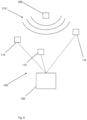
- Fig. 2 shows a schematic representation of a system 100 according to one exemplary embodiment of the present invention.
- the system 100 comprises a multiplicity of receivers 110 of which a total of three are shown in Fig. 2 , and also a central control unit 120.
- a transmitter 200 emits signals 210.
- the multiplicity of receivers 110 are connected to the central control unit 120 and can be synchronized by the central control unit 120 by forwarding a list of measurement parameters.
- This list of measurement parameters contains a multiplicity of measurement time intervals at which the receivers are intended to measure signals.
- the measurement time intervals are the same for all of the multiplicity of receivers 110 and cover a long time period, whereby the measurements of the multiplicity of receivers 110 take place over this entire time period.
- each of the multiplicity of receivers 110 carries out a measurement with which it is possible to detect whether a signal 210 emitted by the transmitter 200 has or has not reached the respective receiver 110 in this measurement time interval.
- Data relating to these measurements, indicating, in particular, whether signals 210 have or have not been measured, or indicating the measurement time interval in which a receiver 110 has measured a signal are forwarded from the receivers 110 to the central control unit 120.
- the central control unit can determine the position of the transmitter 200 by means of these data and data relating to the positions of the individual receivers 110.
- the measurement time intervals can be defined, for example, by means of the measurement start time, measurement time interval length and/or measurement duration contained in the list of parameters.
- the measured parameters can further contain a frequency measurement range.
- the receivers which can generally measure signals and frequencies outside this frequency range can thereby be tuned to the transmitter of which the position is intended to be determined.
- This frequency range can further be divided into a multiplicity of sub-ranges, wherein one of the multiplicity of sub-ranges is assigned to each of the multiplicity of measurement intervals.
- the signals 210 emitted by the transmitter 200 generally have specific frequency characteristics, since the signals can, for example, undergo different frequency shifts due to varying differential speeds between the transmitter 200 and the receiver 110, the measurement of the signals 210 by the individual receivers 110 can be optimized as a result.
- the receivers 110 can forward the signals measured by them directly to the central control unit 120 which can then determine whether the measured signals 210 originate from the transmitter 200. Measured signals 210 which are categorized as not originating from the transmitter 200 can be ignored for the purposes of determining the position of the transmitter 200, thereby improving the position determination.
- the receivers 110 can be designed such that the multiplicity of receivers 110 can determine independently whether the measured signals 210 originate from the transmitter 200. In this case, the data relating to the measured signals 210 can be kept more simple, thereby reducing the required bandwidth for the communication between the receivers 110 and the central control unit 120.
- the receivers 110 can additionally be designed such that the data relating to the measured signals 210 are transmitted only if it has been determined that the measured signals 210 originate from the transmitter 200. Even more bandwidth can thereby be saved, and errors due to overlapping communication can be avoided.
- Fig. 2 shows only one single transmitter 200, the position of which is intended to be determined. However, the positions of a plurality of transmitters can also be determined with the system 100 shown.
- the multiplicity of receivers 110 can be designed as stationary and/or mobile, depending on the application.
Landscapes
- Physics & Mathematics (AREA)
- Engineering & Computer Science (AREA)
- General Physics & Mathematics (AREA)
- Radar, Positioning & Navigation (AREA)
- Remote Sensing (AREA)
- Position Fixing By Use Of Radio Waves (AREA)
- Measurement Of Velocity Or Position Using Acoustic Or Ultrasonic Waves (AREA)
Abstract
The present invention relates to a method for determining a position of a transmitter (200), comprising synchronizing a multiplicity of receivers (110) by forwarding a list of measurement parameters from a central control unit (120) to the multiplicity of receivers (110), wherein the list of measurement parameters contains a multiplicity of measurement time intervals; measuring signals (210) by means of the multiplicity of receivers (110) using the list of measurement parameters; forwarding data relating to the measured signals (210) from the multiplicity of receivers (110) to the central control unit (120), wherein the data relating to the measured signals (210) contain a measurement time and a measurement position of the measured signal (210); and evaluating the forwarded data in order to determine the position of the transmitter (200) by means of the central control unit (120). The present invention further relates to a system (100).
Description
- The present invention relates to a method for determining a position of a transmitter, and to a system.
- In many fields of application, particularly, but not exclusively, in the military field, it is often necessary to determine the position of an object which emits signals, in particular electromagnetic signals. For this purpose, methods or systems are used in which a signal emitted by a transmitter, the position of which is intended to be determined, is measured by a multiplicity of receivers, and the position of the transmitter can be determined on the basis of their respective, known positions and the times at which the emitted signal was measured.
- However, these systems have hitherto been developed under the assumption of a cooperative transmitter. In such a case, the time at which the transmitter emits the signal is known, and the receivers can be preset accordingly.
- However, particularly in the military field, the position of a non-cooperative transmitter which emits signals at unknown times is often intended to be determined. Since the preparation of the receivers for a measurement requires a certain amount of time, pauses occur in which the position determining system cannot detect any signals. This is not a problem in the case of cooperative transmitters, since such transmitters are synchronized with these measurement pauses, but it can impair the position determination of non-cooperative transmitters.
- Against this background, the object of the present invention is to improve the reliability of position determinations of objects emitting signals, particularly if said objects do not cooperate.
- This object is achieved by a method for determining a position of a transmitter having the features of patent claim 1, and a system having the features of patent claim 9.
- A method for determining a position of a transmitter is provided accordingly. A multiplicity of receivers are synchronized by forwarding a list of measurement parameters from a central control unit to the multiplicity of receivers, wherein the list of measurement parameters contains a multiplicity of measurement time intervals. Signals are measured by the multiplicity of receivers using the list of measurement parameters. Data relating to the measured signals are forwarded by the multiplicity of receivers to the central control unit, wherein the data relating to the measured signals contain a measurement time and a measurement position of the measured signal. The forwarded data are evaluated by the central control unit in order to determine the position of the transmitter.
- A system is further provided which has a central control unit and a multiplicity of receivers and which is designed to carry out a method according to the invention.
- One idea of the present invention lies in the synchronization of a multiplicity of receivers over a lengthy time period and therefore also over a multiplicity of individual measurements. The measurement pauses of conventional systems and methods can thereby be eliminated or at least reduced, thus significantly increasing the reliability of the position determination, particularly in the case of non-cooperative transmitters of which the existence cannot be predetermined with certainty.
- According to one exemplary embodiment, the list of measurement parameters further contains a measurement start time, a measurement time interval length and/or a measurement duration. This is a particularly advantageous way of defining the measurement time intervals.
- According to one exemplary embodiment, the list of measurement parameters further contains a frequency measurement range. The receivers can thereby be advantageously tuned to the transmitter to be determined.
- According to one development, the frequency measurement range is divided into a multiplicity of sub-ranges and one of the multiplicity of sub-ranges is assigned to each of the multiplicity of measurement intervals. The reliability of the position determination can be advantageously increased as a result.
- According to one exemplary embodiment, the data relating to the measured signals contain the measured signals and the central control unit determines whether the measured signals originate from the transmitter. The reliability of the position determination can be advantageously increased as a result.
- According to one exemplary embodiment, the multiplicity of receivers determine whether the measured signals originate from the transmitter. The bandwidth required for the communication between the receivers and the control unit can be reduced as a result.
- According to one development, each of the multiplicity of receivers transmits the data relating to the measured signals only if it has been determined that the measured signals originate from the transmitter. The bandwidth required for the communication between the receivers and the control unit can be further reduced as a result, and communication errors can be avoided.
- According to one exemplary embodiment, the positions in each case of a multiplicity of transmitters are determined. This can be advantageous in many applications.
- According to one exemplary embodiment, the multiplicity of receivers are designed as stationary and/or mobile. This can be advantageous in many applications.
- The invention is explained below with reference to the figures in the drawings. In the figures:
- Fig. 1
- shows a schematic flow diagram of a method for determining a position of a transmitter according to one exemplary embodiment of the present invention; and
- Fig. 2
- shows a schematic representation of a system according to one exemplary embodiment of the present invention.
- In the figures, the same reference signs denote identical or functionally identical components, unless otherwise indicated.
-
Fig. 1 shows a schematic flow diagram of a method M for determining a position of a transmitter according to one exemplary embodiment of the present invention. - In a first method step M1, a multiplicity of receivers are synchronized by forwarding a list of measurement parameters from a central control unit to the multiplicity of receivers, wherein the list of measurement parameters contains a multiplicity of measurement time intervals. In a further method step M2, the signals are measured by the multiplicity of receivers using the list of measurement parameters. In a further method step M3, data relating to the measured signals are forwarded from the multiplicity of receivers to the central control unit, wherein the data relating to the measured signals contain a measurement time and a measurement position of the measured signal. In a further method step M4, the forwarded data are evaluated by the central control unit in order to determine the position of the transmitter.
- The individual method steps of the method M shown here are explained in detail below with reference to
Fig. 2 . -
Fig. 2 shows a schematic representation of asystem 100 according to one exemplary embodiment of the present invention. - The
system 100 comprises a multiplicity ofreceivers 110 of which a total of three are shown inFig. 2 , and also acentral control unit 120. Atransmitter 200 emits signals 210. - The multiplicity of
receivers 110 are connected to thecentral control unit 120 and can be synchronized by thecentral control unit 120 by forwarding a list of measurement parameters. This list of measurement parameters contains a multiplicity of measurement time intervals at which the receivers are intended to measure signals. The measurement time intervals are the same for all of the multiplicity ofreceivers 110 and cover a long time period, whereby the measurements of the multiplicity ofreceivers 110 take place over this entire time period. In each of the multiplicity of measurement time intervals, each of the multiplicity ofreceivers 110 carries out a measurement with which it is possible to detect whether asignal 210 emitted by thetransmitter 200 has or has not reached therespective receiver 110 in this measurement time interval. Data relating to these measurements, indicating, in particular, whethersignals 210 have or have not been measured, or indicating the measurement time interval in which areceiver 110 has measured a signal are forwarded from thereceivers 110 to thecentral control unit 120. The central control unit can determine the position of thetransmitter 200 by means of these data and data relating to the positions of theindividual receivers 110. - The measurement time intervals can be defined, for example, by means of the measurement start time, measurement time interval length and/or measurement duration contained in the list of parameters.
- The measured parameters can further contain a frequency measurement range. The receivers which can generally measure signals and frequencies outside this frequency range can thereby be tuned to the transmitter of which the position is intended to be determined. This frequency range can further be divided into a multiplicity of sub-ranges, wherein one of the multiplicity of sub-ranges is assigned to each of the multiplicity of measurement intervals. As the
signals 210 emitted by thetransmitter 200 generally have specific frequency characteristics, since the signals can, for example, undergo different frequency shifts due to varying differential speeds between thetransmitter 200 and thereceiver 110, the measurement of thesignals 210 by theindividual receivers 110 can be optimized as a result. - In one possible design of the system, the
receivers 110 can forward the signals measured by them directly to thecentral control unit 120 which can then determine whether the measuredsignals 210 originate from thetransmitter 200.Measured signals 210 which are categorized as not originating from thetransmitter 200 can be ignored for the purposes of determining the position of thetransmitter 200, thereby improving the position determination. - Alternatively or additionally, the
receivers 110 can be designed such that the multiplicity ofreceivers 110 can determine independently whether the measuredsignals 210 originate from thetransmitter 200. In this case, the data relating to the measuredsignals 210 can be kept more simple, thereby reducing the required bandwidth for the communication between thereceivers 110 and thecentral control unit 120. Thereceivers 110 can additionally be designed such that the data relating to the measuredsignals 210 are transmitted only if it has been determined that the measuredsignals 210 originate from thetransmitter 200. Even more bandwidth can thereby be saved, and errors due to overlapping communication can be avoided. -
Fig. 2 shows only onesingle transmitter 200, the position of which is intended to be determined. However, the positions of a plurality of transmitters can also be determined with thesystem 100 shown. - The multiplicity of
receivers 110 can be designed as stationary and/or mobile, depending on the application. -
- M
- Method for determining a position of a transmitter
- M1
- Method step for synchronizing a multiplicity of receivers
- M2
- Method step for measuring signals
- M3
- Method step for forwarding data
- M4
- Method step for evaluating data
- 100
- System
- 110
- Receiver
- 120
- Central control unit
- 200
- Transmitter
- 210
- Signal
Claims (10)
- Method (M) for determining a position of a transmitter (200), comprising:- synchronizing (M1) a multiplicity of receivers (110) by forwarding a list of measurement parameters from a central control unit (120) to the multiplicity of receivers (110), wherein the list of measurement parameters contains a multiplicity of measurement time intervals;- measuring (M2) signals (210) by means of the multiplicity of receivers (110) using the list of measurement parameters;- forwarding (M3) data relating to the measured signals (210) from the multiplicity of receivers (110) to the central control unit (120), wherein the data relating to the measured signals (210) contain a measurement time and a measurement position of the measured signal (210); and- evaluating (M4) the forwarded data in order to determine the position of the transmitter (200) by means of the central control unit (120).
- Method (M) according to Claim 1, wherein the list of measurement parameters further contains a measurement start time, a measurement time interval length and/or a measurement duration.
- Method (M) according to one of Claims 1 or 2, wherein the list of measurement parameters further contains a frequency measurement range.
- Method (M) according to claim 3, wherein the frequency measurement range is divided into a multiplicity of sub-ranges and one of the multiplicity of sub-ranges is assigned to each of the multiplicity of measurement intervals.
- Method (M) according to one of the preceding claims, wherein the data relating to the measured signals (210) contain the measured signals (210) and the central control unit (120) determines whether the measured signals (210) originate from the transmitter (200).
- Method (M) according to one of the preceding claims, wherein the multiplicity of receivers (110) determine whether the measured signals (210) originate from the transmitter (200).
- Method (M) according to Claim 6, wherein each of the multiplicity of receivers (110) transmits the data relating to the measured signals (210) only if it has been determined that the measured signals (210) originate from the transmitter (200).
- Method (M) according to one of the preceding claims, wherein the positions in each case of a multiplicity of transmitters (200) are determined.
- System (100) having a multiplicity of receivers (110) and a central control unit (120) which is designed to carry out a method (M) according to one of Claims 1 to 8.
- System (100) according to Claim 9, wherein the multiplicity of receivers (110) are designed as stationary and/or mobile.
Applications Claiming Priority (1)
| Application Number | Priority Date | Filing Date | Title |
|---|---|---|---|
| DE102023105658.1A DE102023105658A1 (en) | 2023-03-07 | 2023-03-07 | METHOD FOR DETERMINING A POSITION OF A TRANSMITTER AND SYSTEM |
Publications (1)
| Publication Number | Publication Date |
|---|---|
| EP4428562A1 true EP4428562A1 (en) | 2024-09-11 |
Family
ID=89843454
Family Applications (1)
| Application Number | Title | Priority Date | Filing Date |
|---|---|---|---|
| EP24155660.4A Pending EP4428562A1 (en) | 2023-03-07 | 2024-02-05 | Method for determining a position of a transmitter, and system |
Country Status (3)
| Country | Link |
|---|---|
| US (1) | US20240302487A1 (en) |
| EP (1) | EP4428562A1 (en) |
| DE (1) | DE102023105658A1 (en) |
Citations (5)
| Publication number | Priority date | Publication date | Assignee | Title |
|---|---|---|---|---|
| US20030092448A1 (en) * | 2001-08-16 | 2003-05-15 | Forstrom Howard Scott | System for determining position of an emitter |
| EP3128337A1 (en) * | 2015-08-02 | 2017-02-08 | Elta Systems Ltd. | System and method for locating a signal source |
| AU2015386249A1 (en) * | 2015-03-11 | 2017-10-26 | Skyrobot Inc. | Search/rescue system |
| US20190204404A1 (en) * | 2017-12-31 | 2019-07-04 | Elta Systems Ltd. | Systems and methods for locating a signal source |
| US20190339352A1 (en) * | 2017-02-27 | 2019-11-07 | Murata Manufacturing Co., Ltd. | Position detecting system |
Family Cites Families (4)
| Publication number | Priority date | Publication date | Assignee | Title |
|---|---|---|---|---|
| US7136016B1 (en) * | 2005-05-16 | 2006-11-14 | The Boeing Company | Platform position location and control |
| EP2426505B1 (en) * | 2010-09-06 | 2013-01-02 | Alcatel Lucent | Localization of mobile terminals in a radio network |
| DE102017222216B3 (en) * | 2017-12-07 | 2019-05-29 | Volkswagen Aktiengesellschaft | Method for carrying out distance measurements between the vehicles of a vehicle convoy and vehicle module for use in the method and vehicle |
| US10495737B1 (en) * | 2019-02-07 | 2019-12-03 | Clairvoyant Networks, LLC | Methods, systems, and computer readable media for time-slotted ultra-wide-band object tracking |
-
2023
- 2023-03-07 DE DE102023105658.1A patent/DE102023105658A1/en active Pending
-
2024
- 2024-02-05 EP EP24155660.4A patent/EP4428562A1/en active Pending
- 2024-03-06 US US18/596,958 patent/US20240302487A1/en active Pending
Patent Citations (5)
| Publication number | Priority date | Publication date | Assignee | Title |
|---|---|---|---|---|
| US20030092448A1 (en) * | 2001-08-16 | 2003-05-15 | Forstrom Howard Scott | System for determining position of an emitter |
| AU2015386249A1 (en) * | 2015-03-11 | 2017-10-26 | Skyrobot Inc. | Search/rescue system |
| EP3128337A1 (en) * | 2015-08-02 | 2017-02-08 | Elta Systems Ltd. | System and method for locating a signal source |
| US20190339352A1 (en) * | 2017-02-27 | 2019-11-07 | Murata Manufacturing Co., Ltd. | Position detecting system |
| US20190204404A1 (en) * | 2017-12-31 | 2019-07-04 | Elta Systems Ltd. | Systems and methods for locating a signal source |
Also Published As
| Publication number | Publication date |
|---|---|
| US20240302487A1 (en) | 2024-09-12 |
| DE102023105658A1 (en) | 2024-09-12 |
Similar Documents
| Publication | Publication Date | Title |
|---|---|---|
| KR102682267B1 (en) | Method and apparatus for operating a plurality of sensors in a vehicle | |
| US10966175B2 (en) | Position detection of user equipment within a wireless telecommunication network | |
| US10859708B2 (en) | Satellite positioning system receiver capable of detecting failure in RF receiver unit including receiving antenna | |
| CN110121657B (en) | Positioning based on message splitting | |
| US10386458B2 (en) | Radar signal processing device and method | |
| US9322899B2 (en) | Method and system for locating a current position or a coupling location of a mobile unit using a leaky waveguide | |
| JP2021519940A (en) | Monitoring of FMCW radar sensor | |
| EP2101518A1 (en) | Finding the position of a mobile terminal | |
| CN102195721B (en) | Method and apparatus for detecting cancellation signal of transmission leakage signal in RF transceiver | |
| KR101206873B1 (en) | Method for synchronising clock pulse devices | |
| KR100778309B1 (en) | Apparatus and Method for computing location of a moving beacon using received signal strength and multi-frequencies | |
| JP2006349515A (en) | Displacement measurement system and displacement measurement method | |
| US20240302487A1 (en) | Method for determining a position of a transmitter, and system | |
| KR101427804B1 (en) | Digital receiver and signal processing method thereof | |
| KR101952748B1 (en) | Apparatus and method for timing synchronization of time division multiple access network node | |
| KR101871554B1 (en) | Central station, positioning system, positioning method, and storage medium | |
| US20240292266A1 (en) | Wireless communication system, aggregation device, interference source air time acquisition method, and interference source air time acquisition program | |
| US8059755B2 (en) | Method for discerning a desired signal from an interfering signal in an under sampled system | |
| GB2603062A (en) | Improved OFDM ranging using position reference symbol phase | |
| US11079463B2 (en) | Method and device for position determination | |
| CN111511015B (en) | Method and device for detecting at least one radio signal in a time-slotted manner | |
| US7630728B2 (en) | Method and system for synchronizing a network of RF devices | |
| KR20140072631A (en) | Network testing system and the operating method | |
| EP4394434A1 (en) | Vibration estimation system and method | |
| AU2004305621A1 (en) | Method for monitoring the time synchronisation of emitters in a common wave network |
Legal Events
| Date | Code | Title | Description |
|---|---|---|---|
| PUAI | Public reference made under article 153(3) epc to a published international application that has entered the european phase |
Free format text: ORIGINAL CODE: 0009012 |
|
| STAA | Information on the status of an ep patent application or granted ep patent |
Free format text: STATUS: THE APPLICATION HAS BEEN PUBLISHED |
|
| AK | Designated contracting states |
Kind code of ref document: A1 Designated state(s): AL AT BE BG CH CY CZ DE DK EE ES FI FR GB GR HR HU IE IS IT LI LT LU LV MC ME MK MT NL NO PL PT RO RS SE SI SK SM TR |
|
| STAA | Information on the status of an ep patent application or granted ep patent |
Free format text: STATUS: REQUEST FOR EXAMINATION WAS MADE |
|
| 17P | Request for examination filed |
Effective date: 20250227 |