EP4428503A1 - Distribution supply apparatus and combination weighing apparatus including the same - Google Patents
Distribution supply apparatus and combination weighing apparatus including the same Download PDFInfo
- Publication number
- EP4428503A1 EP4428503A1 EP24160468.5A EP24160468A EP4428503A1 EP 4428503 A1 EP4428503 A1 EP 4428503A1 EP 24160468 A EP24160468 A EP 24160468A EP 4428503 A1 EP4428503 A1 EP 4428503A1
- Authority
- EP
- European Patent Office
- Prior art keywords
- plate
- support shaft
- articles
- distributor
- universal joint
- Prior art date
- Legal status (The legal status is an assumption and is not a legal conclusion. Google has not performed a legal analysis and makes no representation as to the accuracy of the status listed.)
- Granted
Links
Images



Classifications
-
- B—PERFORMING OPERATIONS; TRANSPORTING
- B65—CONVEYING; PACKING; STORING; HANDLING THIN OR FILAMENTARY MATERIAL
- B65G—TRANSPORT OR STORAGE DEVICES, e.g. CONVEYORS FOR LOADING OR TIPPING, SHOP CONVEYOR SYSTEMS OR PNEUMATIC TUBE CONVEYORS
- B65G69/00—Auxiliary measures taken, or devices used, in connection with loading or unloading
- B65G69/04—Spreading out the materials conveyed over the whole surface to be loaded; Trimming heaps of loose materials
-
- G—PHYSICS
- G01—MEASURING; TESTING
- G01G—WEIGHING
- G01G13/00—Weighing apparatus with automatic feed or discharge for weighing-out batches of material
- G01G13/16—Means for automatically discharging weigh receptacles under control of the weighing mechanism
- G01G13/22—Means for automatically discharging weigh receptacles under control of the weighing mechanism by tilting or rotating the weigh receptacle
-
- G—PHYSICS
- G01—MEASURING; TESTING
- G01G—WEIGHING
- G01G19/00—Weighing apparatus or methods adapted for special purposes not provided for in the preceding groups
- G01G19/387—Weighing apparatus or methods adapted for special purposes not provided for in the preceding groups for combinatorial weighing, i.e. selecting a combination of articles whose total weight or number is closest to a desired value
- G01G19/393—Weighing apparatus or methods adapted for special purposes not provided for in the preceding groups for combinatorial weighing, i.e. selecting a combination of articles whose total weight or number is closest to a desired value using two or more weighing units
-
- A—HUMAN NECESSITIES
- A22—BUTCHERING; MEAT TREATMENT; PROCESSING POULTRY OR FISH
- A22C—PROCESSING MEAT, POULTRY, OR FISH
- A22C21/00—Processing poultry
- A22C21/0053—Transferring or conveying devices for poultry
-
- B—PERFORMING OPERATIONS; TRANSPORTING
- B65—CONVEYING; PACKING; STORING; HANDLING THIN OR FILAMENTARY MATERIAL
- B65G—TRANSPORT OR STORAGE DEVICES, e.g. CONVEYORS FOR LOADING OR TIPPING, SHOP CONVEYOR SYSTEMS OR PNEUMATIC TUBE CONVEYORS
- B65G43/00—Control devices, e.g. for safety, warning or fault-correcting
- B65G43/08—Control devices operated by article or material being fed, conveyed or discharged
-
- B—PERFORMING OPERATIONS; TRANSPORTING
- B65—CONVEYING; PACKING; STORING; HANDLING THIN OR FILAMENTARY MATERIAL
- B65G—TRANSPORT OR STORAGE DEVICES, e.g. CONVEYORS FOR LOADING OR TIPPING, SHOP CONVEYOR SYSTEMS OR PNEUMATIC TUBE CONVEYORS
- B65G65/00—Loading or unloading
- B65G65/30—Methods or devices for filling or emptying bunkers, hoppers, tanks, or like containers, of interest apart from their use in particular chemical or physical processes or their application in particular machines, e.g. not covered by a single other subclass
- B65G65/32—Filling devices
-
- B—PERFORMING OPERATIONS; TRANSPORTING
- B65—CONVEYING; PACKING; STORING; HANDLING THIN OR FILAMENTARY MATERIAL
- B65G—TRANSPORT OR STORAGE DEVICES, e.g. CONVEYORS FOR LOADING OR TIPPING, SHOP CONVEYOR SYSTEMS OR PNEUMATIC TUBE CONVEYORS
- B65G65/00—Loading or unloading
- B65G65/30—Methods or devices for filling or emptying bunkers, hoppers, tanks, or like containers, of interest apart from their use in particular chemical or physical processes or their application in particular machines, e.g. not covered by a single other subclass
- B65G65/34—Emptying devices
- B65G65/40—Devices for emptying otherwise than from the top
-
- B—PERFORMING OPERATIONS; TRANSPORTING
- B65—CONVEYING; PACKING; STORING; HANDLING THIN OR FILAMENTARY MATERIAL
- B65G—TRANSPORT OR STORAGE DEVICES, e.g. CONVEYORS FOR LOADING OR TIPPING, SHOP CONVEYOR SYSTEMS OR PNEUMATIC TUBE CONVEYORS
- B65G69/00—Auxiliary measures taken, or devices used, in connection with loading or unloading
- B65G69/04—Spreading out the materials conveyed over the whole surface to be loaded; Trimming heaps of loose materials
- B65G69/0425—Spreading out the materials conveyed over the whole surface to be loaded; Trimming heaps of loose materials with vibrating or shaking means
-
- B—PERFORMING OPERATIONS; TRANSPORTING
- B65—CONVEYING; PACKING; STORING; HANDLING THIN OR FILAMENTARY MATERIAL
- B65G—TRANSPORT OR STORAGE DEVICES, e.g. CONVEYORS FOR LOADING OR TIPPING, SHOP CONVEYOR SYSTEMS OR PNEUMATIC TUBE CONVEYORS
- B65G69/00—Auxiliary measures taken, or devices used, in connection with loading or unloading
- B65G69/04—Spreading out the materials conveyed over the whole surface to be loaded; Trimming heaps of loose materials
- B65G69/0433—Spreading out the materials conveyed over the whole surface to be loaded; Trimming heaps of loose materials with screw conveyors
-
- B—PERFORMING OPERATIONS; TRANSPORTING
- B65—CONVEYING; PACKING; STORING; HANDLING THIN OR FILAMENTARY MATERIAL
- B65G—TRANSPORT OR STORAGE DEVICES, e.g. CONVEYORS FOR LOADING OR TIPPING, SHOP CONVEYOR SYSTEMS OR PNEUMATIC TUBE CONVEYORS
- B65G69/00—Auxiliary measures taken, or devices used, in connection with loading or unloading
- B65G69/04—Spreading out the materials conveyed over the whole surface to be loaded; Trimming heaps of loose materials
- B65G69/0458—Spreading out the materials conveyed over the whole surface to be loaded; Trimming heaps of loose materials with rotating means, e.g. tables, arms
-
- G—PHYSICS
- G01—MEASURING; TESTING
- G01G—WEIGHING
- G01G13/00—Weighing apparatus with automatic feed or discharge for weighing-out batches of material
- G01G13/02—Means for automatically loading weigh pans or other receptacles, e.g. disposable containers, under control of the weighing mechanism
- G01G13/022—Material feeding devices
- G01G13/026—Material feeding devices by mechanical conveying means, e.g. belt or vibratory conveyor
-
- G—PHYSICS
- G01—MEASURING; TESTING
- G01G—WEIGHING
- G01G21/00—Details of weighing apparatus
-
- G—PHYSICS
- G01—MEASURING; TESTING
- G01G—WEIGHING
- G01G21/00—Details of weighing apparatus
- G01G21/02—Arrangements of bearings
- G01G21/12—Devices for preventing derangement
-
- G—PHYSICS
- G01—MEASURING; TESTING
- G01G—WEIGHING
- G01G23/00—Auxiliary devices for weighing apparatus
-
- B—PERFORMING OPERATIONS; TRANSPORTING
- B65—CONVEYING; PACKING; STORING; HANDLING THIN OR FILAMENTARY MATERIAL
- B65G—TRANSPORT OR STORAGE DEVICES, e.g. CONVEYORS FOR LOADING OR TIPPING, SHOP CONVEYOR SYSTEMS OR PNEUMATIC TUBE CONVEYORS
- B65G2201/00—Indexing codes relating to handling devices, e.g. conveyors, characterised by the type of product or load being conveyed or handled
- B65G2201/02—Articles
- B65G2201/0202—Agricultural and processed food products
-
- B—PERFORMING OPERATIONS; TRANSPORTING
- B65—CONVEYING; PACKING; STORING; HANDLING THIN OR FILAMENTARY MATERIAL
- B65G—TRANSPORT OR STORAGE DEVICES, e.g. CONVEYORS FOR LOADING OR TIPPING, SHOP CONVEYOR SYSTEMS OR PNEUMATIC TUBE CONVEYORS
- B65G2203/00—Indexing code relating to control or detection of the articles or the load carriers during conveying
- B65G2203/02—Control or detection
- B65G2203/0208—Control or detection relating to the transported articles
- B65G2203/0258—Weight of the article
Definitions
- the present invention relates to a distribution supply apparatus and a combination weighing apparatus including the distribution supply apparatus.
- the distribution table rotates around a vertical axis passing through the top at the center. Therefore, the slanted disk rotates together with the distribution table. Thus, broilers dropped from above the slanted disk hit against the slanted disk and then fall to the circumferential edge of the distribution table. Then, due to the rotation of the distribution table, the broilers having fallen to the circumferential edge of the distribution table are discharged to any radial feeders filled with no broiler.
- broilers When a flat expanded broiler, such as a thigh or a breast, adheres to the slanted disk and then a fallen broiler hits against the flat expanded broiler, the broilers are discharged together to the distribution table. Thus, such broilers are overlaid with each other on the distribution table. Due to the overlay, as a problem, temporarily, broilers are difficult to supply to a radial feeder having a small supply.
- a method of controlling the position at which a distribution table stops such that a slanted disk is oriented to a radial feeder having a small supply according to the invention disclosed in FIG. 6 in JP 2007-114185 A .
- a slanted disk and a distribution table require rotating by respective different motors such that the slanted disk is oriented to any empty space on the distribution table.
- such configurations not only need an intricate structure but also require, for example, a camera to capture such an empty space or a radial feeder, leading to an increase in cost as a problem.
- the present invention has been made in order to solve such problems and an object of the present invention is to provide a novel distribution supply apparatus having a simple configuration and capable of distributing randomly fallen articles to the periphery of a slanted disk, and a combination weighing apparatus including the distribution supply apparatus.
- a first aspect of the present invention is summarized as a distribution supply apparatus including: a distributor configured to receive articles dropped from above and distribute the articles circumferentially; a plurality of conveyors arrayed radially along a circumferential edge of the distributor, the plurality of conveyors each being configured to convey, in a direction away from the distributor, an article received from among the articles from the distributor; a support shaft extending vertically and upward from substantially a center of the distributor; a plate configured to change, in contact with each of the articles to fall, a falling direction of each of the articles; a universal joint coupling a center of the plate and a leading end portion of the support shaft; and a regulator configured to regulate an angle of inclination of the plate that slants based on the universal joint, within a range from an angle at which the plate is horizontal to an angle at which each of the articles falls from the plate in a sliding manner.
- the falling position for articles carried by, for example, a conveyor belt is set such that the articles fall to substantially the center of the distributor.
- the plate supported by the universal joint varies its orientation and slant depending on the place against which the article hits.
- each article is oriented to a different direction.
- the articles dropped from above are each distributed to an arc around the support shaft. Therefore, the plate does not require rotating by, for example, a motor, independently of the distributor.
- articles can be distributed to the circumferential edge of the distributor.
- a second aspect of the present invention is summarized as the above distribution supply apparatus further including a second support shaft attached parallel to the plate, the second support shaft extending in a direction intersecting the support shaft, wherein the support shaft rotates together with the distributor around an axis of the support shaft, the universal joint includes a spherical sliding bearing, and the second support shaft is supported by the spherical sliding bearing.
- the second support shaft extending in the direction intersecting the support shaft rotates around the support shaft extending vertically.
- the plate attached parallel to the second support shaft turns around the second support shaft.
- the plate varies in orientation not only in response to a hit with an article but also in response to rotation of the distributor. Even when articles fall randomly, each article is oriented to any direction, so that the articles are distributed annularly around the support shaft.
- a third aspect of the present invention is summarized as the above distribution supply apparatus wherein the regulator includes: a cylinder through which the support shaft is inserted, the cylinder housing the universal joint, the cylinder having an upper end edge configured to regulate a slant of the plate in contact with the plate; and a bottom occluding a lower opening of the cylinder.
- the distribution supply apparatus can be provided to the market as a food processor that inhibits contamination with foreign matter.
- a fourth aspect of the present invention is summarized as a combination weighing apparatus including the above distribution supply apparatus on an upper side of the combination weighing apparatus, wherein each of the plurality of conveyors includes a screw feeder including a screw, the screw feeder being configured to rotate the screw to convey the article or includes a vibration feeder including a trough, the vibration feeder being configured to vibrate the trough to convey the article.
- the plurality of conveyors of the distribution supply apparatus is disposed one-to-one to a plurality of pool hoppers of the combination weighing apparatus.
- the combination weighing apparatus that is of a special type, for example, specialized in broilers and is inexpensive with a reduction in cost.
- a distribution supply apparatus enables changes in the orientation and slant of a plate due to a hit of a fallen article to the plate without a configuration in which the orientation of the plate is changed actively by a motor or the like.
- the distribution supply apparatus low in cost can be provided to the market.
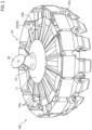
- FIG. 1 is an external perspective view of the entire configuration of a combination weighing apparatus W according to an embodiment of the present invention.
- FIG. 2 is an external perspective view of an exemplary distribution supply apparatus 100 according to another embodiment disposed on the upper side of the combination weighing apparatus W.
- the combination weighing apparatus W includes a distribution supply apparatus 100 provided on its upper side, a plurality of pool hoppers PH disposed below the distribution supply apparatus 100, a plurality of weighing hoppers WH that is disposed below the plurality of pool hoppers PH and is identical in number to the plurality of pool hoppers PH, and a collecting chute CS disposed below the plurality of weighing hoppers WH.
- a distribution supply apparatus 100 provided on its upper side
- a plurality of pool hoppers PH disposed below the distribution supply apparatus 100
- a plurality of weighing hoppers WH that is disposed below the plurality of pool hoppers PH and is identical in number to the plurality of pool hoppers PH
- a collecting chute CS disposed below the plurality of weighing hoppers WH.
- Such a configuration is publicly known, and thus the weighing hoppers WH and the collecting chute CS below the pool hoppers PH are not illustrated in FIG. 2 .
- the distribution supply apparatus 100 includes a distributor 10 at its center and a plurality of conveyors 20 arrayed radially along the circumferential edge of the distributor 10.
- the distributor 10 includes a distribution table 11 gently frustoconical in shape, a driver not illustrated that rotates the distribution table 11 around a vertical axis, a truncated cone 12 attached to the center of the distribution table 11, and a plate 50 attached to the top of the truncated cone 12 through a support shaft 30.
- the conveyors 20 illustrated in FIG. 1 each serve as a screw feeder including a trough 21, of which the cross section is U-shaped, and a screw 22 that rotates inside the trough 21.
- the screw feeder is suitable to conveyance of blockish articles.
- a vibration trough 23 as illustrated in FIG. 2 is adopted.
- Vibration troughs 23 illustrated in FIG. 2 each have an article conveyance face 23a on which a plurality of small projections is arrayed all over in a brick pattern, in which each small projection has an upward slope to the downstream pool hopper PH and is shaped like a rectangle in plan view and a right-angled triangle in side view.
- the article conveyance face 23a conveys articles downstream due to an electromagnetic vibrator (not illustrated) and a four-bar linkage spring mechanism (not illustrated).
- the plurality of vibration troughs 23 arrayed radially is overlapped one on another at adjacent portions 23b in a non-contact manner.
- the vibration troughs 23 serve collectively as a single receiver, so that an article having jumped after hitting against the plate 50 can be received by any of the vibration troughs 23.
- FIG. 3 illustrates an exemplary attachment structure of the plate 50 for attachment onto the truncated cone 12 on the distribution table 11.
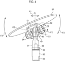
- FIG. 4 is an external perspective view illustrating a state where a regulator 60, described later, in FIG. 3 is removed.
- the support shaft 30 has a leading end portion on which a rod end 31 is screwed.
- the rod end 31 has a leading end portion to which a universal joint 40 is assembled.
- the plate 50 is coupled to the universal joint 40.
- the regulator 60 that regulates the slant of the plate 50 is attached below the plate 50.
- the plate 50 is made of a stainless disk having a size, for example, a diameter of approximately 15 to 20 cm such that the orientation of the plate 50 varies when an article M dropped from above hits against the plate 50.
- a bracket 51 that is U-shaped in side view is welded to the center of the back face of the plate 50 such that the bracket 51 has opposed side faces 52 perpendicular to the back face of the plate 50.
- the universal joint 40 has a spherical sliding bearing 41 disposed between the side faces 52 perpendicular to the back face of the plate 50.
- a bolt 53 inserted through the spherical sliding bearing 41 and the respective through holes of the side faces 52 is secured with a nut 54. Therefore, the bolt 53 serves as a pivot (second support shaft) that causes the plate 50 to slant.
- the bolt 53 extends in a direction intersecting the support shaft 30 extending vertically.
- the support shaft 30 extending vertically rotates in an arrow direction F1 around its axis C1
- the bolt 53 serving as the second support shaft rotates in the arrow direction F1 around the axis C1 of the support shaft 30.
- the bolt 53 serving as the second support shaft is attached parallel to the plate 50.
- the spherical sliding bearing 41 of the universal joint 40 turns in an arrow direction F2 around the axis C2 of the bolt 53 while supporting the bolt (second support shaft) 53 and simultaneously swings in an arrow direction F3 around a horizontal axis C3 intersecting the drawing plane at a slant. Therefore, the plate 50 attached parallel to the second support shaft 53 rotates or turns freely in the three arrow directions F1 to F3.
- the regulator 60 illustrated in FIG. 5 regulates the slant of the plate 50 that slants from the horizontal pose to the vertical pose.
- the regulator 60 is designed such that the plate 50 slants in the range from the horizontal pose to a pose from which an article M falls.
- the angle at which the article M falls depends on the viscosity of the article M or the surface roughness of the plate 50. Thus, the angle is determined based on experiments.
- the regulator 60 includes a cylinder 61 large enough to house the universal joint 40 and a bottom 62 that occludes the lower opening of the cylinder 61.
- the bottom 62 is provided with a through hole 63 for attaching the regulator 60 to the support shaft 30.
- the support shaft 30 has an upper end portion provided with a bolt 32.
- the bolt 32 is screwed to a screw hole with which the bottom face of the rod end 31 is provided.
- the support shaft 30 having the bolt 32 inserted through the through hole 63 of the regulator 60 the bolt 32 is screwed to the screw hole of the rod end 31, so that the regulator 60 can be secured between the upper end face of the support shaft 30 and the bottom face of the rod end 31.
- the cylinder 61 of the regulator 60 has a side face provided with a window 64 for insertion of a wrench, and the support shaft 30 and the rod end 31 each have a side face provided with an I-shaped cut 33 engageable with the wrench.
- the plate 50 having such a configuration as above is disposed at a position to which articles M fall. Every time an article M hits against the plate 50 supported by the universal joint 40, the orientation and slant of the plate 50 vary. Thus, each article M having hit against the plate 50 is oriented to a different direction. Even in a case where articles M fall constantly to the same position, the articles M are distributed properly around the truncated cone 12.
- the plate 50 since the support shaft 30 that supports the plate 50 rotates around the vertical axis, the plate 50 varies in orientation based on its active rotation. Even in a case where articles M fall constantly to the same position, the plate 50 can distribute the articles M properly around the truncated cone 12.
- the present invention is not limited to the embodiments, and thus can be carried out in modified and altered aspects without departing from the gist and scope of the present invention in the claims.
- the distribution table 11 may repeat an arc motion and an up-and-down motion in a spiral manner within a certain angle range.
- the universal joint 40 has the spherical sliding bearing 41 as a bearing.
- a universal joint having two orthogonal shafts may be adopted.
- a bearing that bears a radial load may bear the second support shaft 53 such that the rod end 31 itself rotates freely around the vertical axis. Therefore, the present specification is exemplary and thus does not have any limitative meanings to the present invention.
Landscapes
- Engineering & Computer Science (AREA)
- Physics & Mathematics (AREA)
- General Physics & Mathematics (AREA)
- Mechanical Engineering (AREA)
- Life Sciences & Earth Sciences (AREA)
- Wood Science & Technology (AREA)
- Zoology (AREA)
- Food Science & Technology (AREA)
- Feeding Of Articles To Conveyors (AREA)
Abstract
Description
- The present invention relates to a distribution supply apparatus and a combination weighing apparatus including the distribution supply apparatus.
- In order to weigh articles high in adhesion, such as disassembled broilers, in combination, as disclosed in
JP 2018-155636 A - The distribution table rotates around a vertical axis passing through the top at the center. Therefore, the slanted disk rotates together with the distribution table. Thus, broilers dropped from above the slanted disk hit against the slanted disk and then fall to the circumferential edge of the distribution table. Then, due to the rotation of the distribution table, the broilers having fallen to the circumferential edge of the distribution table are discharged to any radial feeders filled with no broiler.
-
- Patent Literature 1:
JP2018-155636A1 - Patent Literature 2:
JP2007-114185A1 - However, since the slanted disk rotates together with the distribution table, the slanted disk is difficult to orient to any empty space on the distribution table. As a result, only control to rotate the distribution table or stop the rotation of the distribution table has difficulty in distributing fallen broilers evenly to the circumferential edge of the distribution table, leading to a problem.
- When a flat expanded broiler, such as a thigh or a breast, adheres to the slanted disk and then a fallen broiler hits against the flat expanded broiler, the broilers are discharged together to the distribution table. Thus, such broilers are overlaid with each other on the distribution table. Due to the overlay, as a problem, temporarily, broilers are difficult to supply to a radial feeder having a small supply.
- In order to solve such problems, for example, required is a method of controlling the position at which a distribution table stops such that a slanted disk is oriented to a radial feeder having a small supply, according to the invention disclosed in FIG. 6 in
JP 2007-114185 A - The present invention has been made in order to solve such problems and an object of the present invention is to provide a novel distribution supply apparatus having a simple configuration and capable of distributing randomly fallen articles to the periphery of a slanted disk, and a combination weighing apparatus including the distribution supply apparatus.
- A first aspect of the present invention is summarized as a distribution supply apparatus including: a distributor configured to receive articles dropped from above and distribute the articles circumferentially; a plurality of conveyors arrayed radially along a circumferential edge of the distributor, the plurality of conveyors each being configured to convey, in a direction away from the distributor, an article received from among the articles from the distributor; a support shaft extending vertically and upward from substantially a center of the distributor; a plate configured to change, in contact with each of the articles to fall, a falling direction of each of the articles; a universal joint coupling a center of the plate and a leading end portion of the support shaft; and a regulator configured to regulate an angle of inclination of the plate that slants based on the universal joint, within a range from an angle at which the plate is horizontal to an angle at which each of the articles falls from the plate in a sliding manner.
- In the distribution supply apparatus, the falling position for articles carried by, for example, a conveyor belt is set such that the articles fall to substantially the center of the distributor. Thus, when an article falls onto the plate located at substantially the center of the distributor, the plate supported by the universal joint varies its orientation and slant depending on the place against which the article hits. Thus, even when articles fall one after another, each article is oriented to a different direction. Thus, the articles dropped from above are each distributed to an arc around the support shaft. Therefore, the plate does not require rotating by, for example, a motor, independently of the distributor. Thus, with a reduction in cost, articles can be distributed to the circumferential edge of the distributor.
- A second aspect of the present invention is summarized as the above distribution supply apparatus further including a second support shaft attached parallel to the plate, the second support shaft extending in a direction intersecting the support shaft, wherein the support shaft rotates together with the distributor around an axis of the support shaft, the universal joint includes a spherical sliding bearing, and the second support shaft is supported by the spherical sliding bearing.
- Thus, when the support shaft extending vertically rotates in the horizontal plane, the second support shaft extending in the direction intersecting the support shaft rotates around the support shaft extending vertically. Simultaneously, the plate attached parallel to the second support shaft turns around the second support shaft. Thus, the plate varies in orientation not only in response to a hit with an article but also in response to rotation of the distributor. Even when articles fall randomly, each article is oriented to any direction, so that the articles are distributed annularly around the support shaft.
- A third aspect of the present invention is summarized as the above distribution supply apparatus wherein the regulator includes: a cylinder through which the support shaft is inserted, the cylinder housing the universal joint, the cylinder having an upper end edge configured to regulate a slant of the plate in contact with the plate; and a bottom occluding a lower opening of the cylinder.
- Thus, since the universal joint movable is housed in the cylinder, even in a case where the universal joint abrades, the universal joint can be kept inside the cylinder, leading to prevention of the universal joint from falling to the distributor. Therefore, the distribution supply apparatus can be provided to the market as a food processor that inhibits contamination with foreign matter.
- A fourth aspect of the present invention is summarized as a combination weighing apparatus including the above distribution supply apparatus on an upper side of the combination weighing apparatus, wherein each of the plurality of conveyors includes a screw feeder including a screw, the screw feeder being configured to rotate the screw to convey the article or includes a vibration feeder including a trough, the vibration feeder being configured to vibrate the trough to convey the article.
- The plurality of conveyors of the distribution supply apparatus is disposed one-to-one to a plurality of pool hoppers of the combination weighing apparatus. Thus, to the market, provided can be the combination weighing apparatus that is of a special type, for example, specialized in broilers and is inexpensive with a reduction in cost.
- According to the present invention, a distribution supply apparatus enables changes in the orientation and slant of a plate due to a hit of a fallen article to the plate without a configuration in which the orientation of the plate is changed actively by a motor or the like. Thus, the distribution supply apparatus low in cost can be provided to the market.
-
-
FIG. 1 is an external perspective view of a combination weighing apparatus according to an embodiment of the present invention; -
FIG. 2 is an external perspective view of a distribution supply apparatus according to another embodiment; -
FIG. 3 is an external perspective view of the entire attachment structure of a plate; -
FIG. 4 is an external perspective view illustrating a state where a regulator is removed from the attachment structure inFIG. 3 ; and -
FIG. 5 is an external perspective view of the regulator. - Embodiments of the present invention will be described below based on the drawings. Note that the drawings are schematic and thus the parts are different in dimensions or ratio from the realities. In addition, parts between each drawing may be different in dimensions or ratio. Furthermore, in the present specification and the drawings, constituents substantially identical in function or configuration are denoted with the same reference signs and thus duplicate description thereof will be omitted. In addition, any constituents not directly related to the present invention are not illustrated.
-
FIG. 1 is an external perspective view of the entire configuration of a combination weighing apparatus W according to an embodiment of the present invention.FIG. 2 is an external perspective view of an exemplarydistribution supply apparatus 100 according to another embodiment disposed on the upper side of the combination weighing apparatus W. - Referring to
FIGS. 1 and2 , the combination weighing apparatus W includes adistribution supply apparatus 100 provided on its upper side, a plurality of pool hoppers PH disposed below thedistribution supply apparatus 100, a plurality of weighing hoppers WH that is disposed below the plurality of pool hoppers PH and is identical in number to the plurality of pool hoppers PH, and a collecting chute CS disposed below the plurality of weighing hoppers WH. Such a configuration is publicly known, and thus the weighing hoppers WH and the collecting chute CS below the pool hoppers PH are not illustrated inFIG. 2 . For example, the pool hoppers PH, the weighing hoppers WH, and the collecting chute CS illustrated inFIG. 1 are publicly known in configuration, and thus detailed descriptions thereof will be omitted herein. - Referring to
FIGS. 1 and2 , thedistribution supply apparatus 100 includes adistributor 10 at its center and a plurality ofconveyors 20 arrayed radially along the circumferential edge of thedistributor 10. Thedistributor 10 includes a distribution table 11 gently frustoconical in shape, a driver not illustrated that rotates the distribution table 11 around a vertical axis, atruncated cone 12 attached to the center of the distribution table 11, and aplate 50 attached to the top of thetruncated cone 12 through asupport shaft 30. - The
conveyors 20 illustrated inFIG. 1 each serve as a screw feeder including atrough 21, of which the cross section is U-shaped, and ascrew 22 that rotates inside thetrough 21. The screw feeder is suitable to conveyance of blockish articles. However, for flat articles, such as thighs or breasts, such avibration trough 23 as illustrated inFIG. 2 is adopted. -
Vibration troughs 23 illustrated inFIG. 2 each have anarticle conveyance face 23a on which a plurality of small projections is arrayed all over in a brick pattern, in which each small projection has an upward slope to the downstream pool hopper PH and is shaped like a rectangle in plan view and a right-angled triangle in side view. Thearticle conveyance face 23a conveys articles downstream due to an electromagnetic vibrator (not illustrated) and a four-bar linkage spring mechanism (not illustrated). The plurality ofvibration troughs 23 arrayed radially is overlapped one on another atadjacent portions 23b in a non-contact manner. Thus, thevibration troughs 23 serve collectively as a single receiver, so that an article having jumped after hitting against theplate 50 can be received by any of thevibration troughs 23. -
FIG. 3 illustrates an exemplary attachment structure of theplate 50 for attachment onto thetruncated cone 12 on the distribution table 11.FIG. 4 is an external perspective view illustrating a state where aregulator 60, described later, inFIG. 3 is removed. Referring toFIGS. 3 and4 , thesupport shaft 30 has a leading end portion on which arod end 31 is screwed. Therod end 31 has a leading end portion to which auniversal joint 40 is assembled. Theplate 50 is coupled to theuniversal joint 40. Theregulator 60 that regulates the slant of theplate 50 is attached below theplate 50. - The
plate 50 is made of a stainless disk having a size, for example, a diameter of approximately 15 to 20 cm such that the orientation of theplate 50 varies when an article M dropped from above hits against theplate 50. Abracket 51 that is U-shaped in side view is welded to the center of the back face of theplate 50 such that thebracket 51 has opposed side faces 52 perpendicular to the back face of theplate 50. - The
universal joint 40 has a spherical slidingbearing 41 disposed between the side faces 52 perpendicular to the back face of theplate 50. Abolt 53 inserted through the spherical slidingbearing 41 and the respective through holes of the side faces 52 is secured with anut 54. Therefore, thebolt 53 serves as a pivot (second support shaft) that causes theplate 50 to slant. Thebolt 53 extends in a direction intersecting thesupport shaft 30 extending vertically. Thus, when thesupport shaft 30 extending vertically rotates in an arrow direction F1 around its axis C1, thebolt 53 serving as the second support shaft rotates in the arrow direction F1 around the axis C1 of thesupport shaft 30. Note that thebolt 53 serving as the second support shaft is attached parallel to theplate 50. - The spherical sliding
bearing 41 of the universal joint 40 turns in an arrow direction F2 around the axis C2 of thebolt 53 while supporting the bolt (second support shaft) 53 and simultaneously swings in an arrow direction F3 around a horizontal axis C3 intersecting the drawing plane at a slant. Therefore, theplate 50 attached parallel to thesecond support shaft 53 rotates or turns freely in the three arrow directions F1 to F3. - The
regulator 60 illustrated inFIG. 5 regulates the slant of theplate 50 that slants from the horizontal pose to the vertical pose. For example, theregulator 60 is designed such that theplate 50 slants in the range from the horizontal pose to a pose from which an article M falls. The angle at which the article M falls depends on the viscosity of the article M or the surface roughness of theplate 50. Thus, the angle is determined based on experiments. Theregulator 60 includes acylinder 61 large enough to house theuniversal joint 40 and a bottom 62 that occludes the lower opening of thecylinder 61. The bottom 62 is provided with a throughhole 63 for attaching theregulator 60 to thesupport shaft 30. - Referring to
FIG. 4 , thesupport shaft 30 has an upper end portion provided with abolt 32. Thebolt 32 is screwed to a screw hole with which the bottom face of therod end 31 is provided. Then, with thesupport shaft 30 having thebolt 32 inserted through the throughhole 63 of theregulator 60, thebolt 32 is screwed to the screw hole of therod end 31, so that theregulator 60 can be secured between the upper end face of thesupport shaft 30 and the bottom face of therod end 31. Thus, thecylinder 61 of theregulator 60 has a side face provided with awindow 64 for insertion of a wrench, and thesupport shaft 30 and therod end 31 each have a side face provided with an I-shapedcut 33 engageable with the wrench. - The
plate 50 having such a configuration as above is disposed at a position to which articles M fall. Every time an article M hits against theplate 50 supported by theuniversal joint 40, the orientation and slant of theplate 50 vary. Thus, each article M having hit against theplate 50 is oriented to a different direction. Even in a case where articles M fall constantly to the same position, the articles M are distributed properly around thetruncated cone 12. - In addition, since the
support shaft 30 that supports theplate 50 rotates around the vertical axis, theplate 50 varies in orientation based on its active rotation. Even in a case where articles M fall constantly to the same position, theplate 50 can distribute the articles M properly around thetruncated cone 12. - Some embodiments of the present invention have been described above. However, the present invention is not limited to the embodiments, and thus can be carried out in modified and altered aspects without departing from the gist and scope of the present invention in the claims. For example, instead of rotation of the distribution table 11, the distribution table 11 may repeat an arc motion and an up-and-down motion in a spiral manner within a certain angle range. The
universal joint 40 has the spherical slidingbearing 41 as a bearing. Instead of theuniversal joint 40, a universal joint having two orthogonal shafts may be adopted. Instead of the spherical slidingbearing 41 of therod end 31, a bearing that bears a radial load may bear thesecond support shaft 53 such that therod end 31 itself rotates freely around the vertical axis. Therefore, the present specification is exemplary and thus does not have any limitative meanings to the present invention. -
- W
- Combination weighing apparatus
- M
- Article
- 10
- Distributor
- 20
- Conveyor
- 22
- Screw
- 23
- Vibration trough (Trough)
- 30
- Support shaft
- 40
- Universal joint
- 41
- Spherical sliding bearing
- 50
- Plate
- 53
- Second support shaft (Bolt)
- 60
- Regulator
- 61
- Cylinder
- 62
- Bottom
- 100
- Distribution supply apparatus
Claims (4)
- A distribution supply apparatus comprising:a distributor configured to receive articles dropped from above and distribute the articles circumferentially;a plurality of conveyors arrayed radially along a circumferential edge of the distributor, the plurality of conveyors each being configured to convey, in a direction away from the distributor, an article received from among the articles from the distributor;a support shaft extending vertically and upward from substantially a center of the distributor;a plate configured to change, in contact with each of the articles to fall, a falling direction of each of the articles;a universal joint coupling a center of the plate and a leading end portion of the support shaft; anda regulator configured to regulate an angle of inclination of the plate that slants based on the universal joint, within a range from an angle at which the plate is horizontal to an angle at which each of the articles falls from the plate in a sliding manner.
- The distribution supply apparatus according to claim 1, further comprising a second support shaft attached parallel to the plate, the second support shaft extending in a direction intersecting the support shaft, wherein the support shaft rotates together with the distributor around an axis of the support shaft, the universal joint includes a spherical sliding bearing, and the second support shaft is supported by the spherical sliding bearing.
- The distribution supply apparatus according to claim 1 or 2, wherein
the regulator includes:a cylinder through which the support shaft is inserted, the cylinder housing the universal joint, the cylinder having an upper end edge configured to regulate a slant of the plate in contact with the plate; anda bottom occluding a lower opening of the cylinder. - A combination weighing apparatus comprising the distribution supply apparatus according to any one of claims 1 to 3 on an upper side of the combination weighing apparatus, wherein
each of the plurality of conveyors includes a screw feeder including a screw, the screw feeder being configured to rotate the screw to convey the article or includes a vibration feeder including a trough, the vibration feeder being configured to vibrate the trough to convey the article.
Applications Claiming Priority (1)
| Application Number | Priority Date | Filing Date | Title |
|---|---|---|---|
| JP2023034828A JP2024126447A (en) | 2023-03-07 | 2023-03-07 | Dispersion supply device and combination weighing device equipped with same |
Publications (2)
| Publication Number | Publication Date |
|---|---|
| EP4428503A1 true EP4428503A1 (en) | 2024-09-11 |
| EP4428503B1 EP4428503B1 (en) | 2025-08-27 |
Family
ID=90123442
Family Applications (1)
| Application Number | Title | Priority Date | Filing Date |
|---|---|---|---|
| EP24160468.5A Active EP4428503B1 (en) | 2023-03-07 | 2024-02-29 | Distribution supply apparatus and combination weighing apparatus including the same |
Country Status (5)
| Country | Link |
|---|---|
| US (1) | US12474196B2 (en) |
| EP (1) | EP4428503B1 (en) |
| JP (1) | JP2024126447A (en) |
| CN (1) | CN118618932A (en) |
| DK (1) | DK4428503T3 (en) |
Families Citing this family (1)
| Publication number | Priority date | Publication date | Assignee | Title |
|---|---|---|---|---|
| CN119527924B (en) * | 2024-11-12 | 2025-11-21 | 苏州圣达生机电设备有限公司 | Wobble plate feeding mechanism and use method thereof |
Citations (2)
| Publication number | Priority date | Publication date | Assignee | Title |
|---|---|---|---|---|
| JP2007114185A (en) | 2005-09-21 | 2007-05-10 | Ishida Co Ltd | Combination weighing device |
| JP2018155636A (en) | 2017-03-17 | 2018-10-04 | 株式会社イシダ | Distribution device and combination measuring device |
Family Cites Families (7)
| Publication number | Priority date | Publication date | Assignee | Title |
|---|---|---|---|---|
| US5270495A (en) * | 1992-02-28 | 1993-12-14 | Package Machinery Company | Combination weighing machine with feed control |
| WO2007034859A1 (en) | 2005-09-21 | 2007-03-29 | Ishida Co., Ltd. | Combination metering device |
| EP2484593A1 (en) * | 2011-02-04 | 2012-08-08 | Cabinplant International A/S | An apparatus for conveying and selectively discharging products |
| JP6389387B2 (en) * | 2014-07-18 | 2018-09-12 | 株式会社イシダ | Combination weighing device |
| WO2018130645A1 (en) * | 2017-01-13 | 2018-07-19 | Marel A/S | A combination weigher |
| JP2020038118A (en) * | 2018-09-04 | 2020-03-12 | 株式会社イシダ | Weighing device |
| WO2020182298A1 (en) * | 2019-03-12 | 2020-09-17 | Cabinplant A/S | A method of weighing and batching articles |
-
2023
- 2023-03-07 JP JP2023034828A patent/JP2024126447A/en active Pending
-
2024
- 2024-01-30 CN CN202410129242.4A patent/CN118618932A/en active Pending
- 2024-02-29 DK DK24160468.5T patent/DK4428503T3/en active
- 2024-02-29 EP EP24160468.5A patent/EP4428503B1/en active Active
- 2024-03-05 US US18/595,858 patent/US12474196B2/en active Active
Patent Citations (2)
| Publication number | Priority date | Publication date | Assignee | Title |
|---|---|---|---|---|
| JP2007114185A (en) | 2005-09-21 | 2007-05-10 | Ishida Co Ltd | Combination weighing device |
| JP2018155636A (en) | 2017-03-17 | 2018-10-04 | 株式会社イシダ | Distribution device and combination measuring device |
Also Published As
| Publication number | Publication date |
|---|---|
| CN118618932A (en) | 2024-09-10 |
| EP4428503B1 (en) | 2025-08-27 |
| DK4428503T3 (en) | 2025-09-15 |
| US12474196B2 (en) | 2025-11-18 |
| JP2024126447A (en) | 2024-09-20 |
| US20240302200A1 (en) | 2024-09-12 |
Similar Documents
| Publication | Publication Date | Title |
|---|---|---|
| EP4428503B1 (en) | Distribution supply apparatus and combination weighing apparatus including the same | |
| US7732718B2 (en) | Combination weighing apparatus with conveying unit including trough and spiral member | |
| US4662508A (en) | Product feeding device for combination weighing machine | |
| US8708632B2 (en) | Active choking funnel for a grain spreader | |
| JP6050690B2 (en) | Combination weighing device | |
| US9523602B2 (en) | Vibrating conical distributing table for a combination weighing apparatus with rotary stirring arms having downwardly extending stirring plates | |
| EP3112825A1 (en) | Combination weighing apparatus | |
| JP2009270986A (en) | Combined weighing instrument | |
| EP0074826B1 (en) | Distribution table for controlling feed rate of articles | |
| JP3530612B2 (en) | Article supply device | |
| US20140299633A1 (en) | Rotary pipe-type linear feeder | |
| US6756546B2 (en) | Combination weighing apparatus | |
| US10472181B1 (en) | Dispersive supply device and combination weighing device | |
| JP5124348B2 (en) | Combination weighing device | |
| JP5230365B2 (en) | Combination weighing device | |
| US20170211967A1 (en) | Combination weighing device | |
| CN106241303B (en) | Columnar member automatic screening feed mechanism | |
| JP7542920B2 (en) | Combination weigher | |
| JP2015215271A (en) | Weighing device | |
| JP2002265031A (en) | Component aligning supplying machine | |
| CN218490986U (en) | Material distributing device of belt conveyor | |
| JP2007114185A (en) | Combination weighing device | |
| CN212607771U (en) | Vibration disc device for walnut feeding and feeding system thereof | |
| JP2020148668A (en) | Combination scale | |
| JP2006199424A (en) | Conveying device and combination weighing device provided with the same |
Legal Events
| Date | Code | Title | Description |
|---|---|---|---|
| PUAI | Public reference made under article 153(3) epc to a published international application that has entered the european phase |
Free format text: ORIGINAL CODE: 0009012 |
|
| STAA | Information on the status of an ep patent application or granted ep patent |
Free format text: STATUS: REQUEST FOR EXAMINATION WAS MADE |
|
| 17P | Request for examination filed |
Effective date: 20240229 |
|
| AK | Designated contracting states |
Kind code of ref document: A1 Designated state(s): AL AT BE BG CH CY CZ DE DK EE ES FI FR GB GR HR HU IE IS IT LI LT LU LV MC ME MK MT NL NO PL PT RO RS SE SI SK SM TR |
|
| GRAP | Despatch of communication of intention to grant a patent |
Free format text: ORIGINAL CODE: EPIDOSNIGR1 |
|
| STAA | Information on the status of an ep patent application or granted ep patent |
Free format text: STATUS: GRANT OF PATENT IS INTENDED |
|
| RIC1 | Information provided on ipc code assigned before grant |
Ipc: G01G 19/393 20060101AFI20250304BHEP |
|
| INTG | Intention to grant announced |
Effective date: 20250325 |
|
| GRAS | Grant fee paid |
Free format text: ORIGINAL CODE: EPIDOSNIGR3 |
|
| GRAA | (expected) grant |
Free format text: ORIGINAL CODE: 0009210 |
|
| STAA | Information on the status of an ep patent application or granted ep patent |
Free format text: STATUS: THE PATENT HAS BEEN GRANTED |
|
| AK | Designated contracting states |
Kind code of ref document: B1 Designated state(s): AL AT BE BG CH CY CZ DE DK EE ES FI FR GB GR HR HU IE IS IT LI LT LU LV MC ME MK MT NL NO PL PT RO RS SE SI SK SM TR |
|
| REG | Reference to a national code |
Ref country code: CH Ref legal event code: EP |
|
| REG | Reference to a national code |
Ref country code: DE Ref legal event code: R096 Ref document number: 602024000525 Country of ref document: DE |
|
| REG | Reference to a national code |
Ref country code: DK Ref legal event code: T3 Effective date: 20250912 |
|
| REG | Reference to a national code |
Ref country code: IE Ref legal event code: FG4D |
|
| REG | Reference to a national code |
Ref country code: NL Ref legal event code: MP Effective date: 20250827 |
|
| PG25 | Lapsed in a contracting state [announced via postgrant information from national office to epo] |
Ref country code: IS Free format text: LAPSE BECAUSE OF FAILURE TO SUBMIT A TRANSLATION OF THE DESCRIPTION OR TO PAY THE FEE WITHIN THE PRESCRIBED TIME-LIMIT Effective date: 20251227 |
|
| PG25 | Lapsed in a contracting state [announced via postgrant information from national office to epo] |
Ref country code: NO Free format text: LAPSE BECAUSE OF FAILURE TO SUBMIT A TRANSLATION OF THE DESCRIPTION OR TO PAY THE FEE WITHIN THE PRESCRIBED TIME-LIMIT Effective date: 20251127 |
|
| REG | Reference to a national code |
Ref country code: LT Ref legal event code: MG9D |
|
| PG25 | Lapsed in a contracting state [announced via postgrant information from national office to epo] |
Ref country code: PT Free format text: LAPSE BECAUSE OF FAILURE TO SUBMIT A TRANSLATION OF THE DESCRIPTION OR TO PAY THE FEE WITHIN THE PRESCRIBED TIME-LIMIT Effective date: 20251229 |
|
| PG25 | Lapsed in a contracting state [announced via postgrant information from national office to epo] |
Ref country code: FI Free format text: LAPSE BECAUSE OF FAILURE TO SUBMIT A TRANSLATION OF THE DESCRIPTION OR TO PAY THE FEE WITHIN THE PRESCRIBED TIME-LIMIT Effective date: 20250827 |
|
| PG25 | Lapsed in a contracting state [announced via postgrant information from national office to epo] |
Ref country code: HR Free format text: LAPSE BECAUSE OF FAILURE TO SUBMIT A TRANSLATION OF THE DESCRIPTION OR TO PAY THE FEE WITHIN THE PRESCRIBED TIME-LIMIT Effective date: 20250827 Ref country code: NL Free format text: LAPSE BECAUSE OF FAILURE TO SUBMIT A TRANSLATION OF THE DESCRIPTION OR TO PAY THE FEE WITHIN THE PRESCRIBED TIME-LIMIT Effective date: 20250827 |
|
| PG25 | Lapsed in a contracting state [announced via postgrant information from national office to epo] |
Ref country code: GR Free format text: LAPSE BECAUSE OF FAILURE TO SUBMIT A TRANSLATION OF THE DESCRIPTION OR TO PAY THE FEE WITHIN THE PRESCRIBED TIME-LIMIT Effective date: 20251128 |
|
| PG25 | Lapsed in a contracting state [announced via postgrant information from national office to epo] |
Ref country code: SE Free format text: LAPSE BECAUSE OF FAILURE TO SUBMIT A TRANSLATION OF THE DESCRIPTION OR TO PAY THE FEE WITHIN THE PRESCRIBED TIME-LIMIT Effective date: 20250827 |
|
| PG25 | Lapsed in a contracting state [announced via postgrant information from national office to epo] |
Ref country code: LV Free format text: LAPSE BECAUSE OF FAILURE TO SUBMIT A TRANSLATION OF THE DESCRIPTION OR TO PAY THE FEE WITHIN THE PRESCRIBED TIME-LIMIT Effective date: 20250827 |
|
| PG25 | Lapsed in a contracting state [announced via postgrant information from national office to epo] |
Ref country code: BG Free format text: LAPSE BECAUSE OF FAILURE TO SUBMIT A TRANSLATION OF THE DESCRIPTION OR TO PAY THE FEE WITHIN THE PRESCRIBED TIME-LIMIT Effective date: 20250827 Ref country code: PL Free format text: LAPSE BECAUSE OF FAILURE TO SUBMIT A TRANSLATION OF THE DESCRIPTION OR TO PAY THE FEE WITHIN THE PRESCRIBED TIME-LIMIT Effective date: 20250827 |
|
| PG25 | Lapsed in a contracting state [announced via postgrant information from national office to epo] |
Ref country code: RS Free format text: LAPSE BECAUSE OF FAILURE TO SUBMIT A TRANSLATION OF THE DESCRIPTION OR TO PAY THE FEE WITHIN THE PRESCRIBED TIME-LIMIT Effective date: 20251127 |
|
| PG25 | Lapsed in a contracting state [announced via postgrant information from national office to epo] |
Ref country code: ES Free format text: LAPSE BECAUSE OF FAILURE TO SUBMIT A TRANSLATION OF THE DESCRIPTION OR TO PAY THE FEE WITHIN THE PRESCRIBED TIME-LIMIT Effective date: 20250827 |
|
| REG | Reference to a national code |
Ref country code: AT Ref legal event code: MK05 Ref document number: 1830390 Country of ref document: AT Kind code of ref document: T Effective date: 20250827 |
|
| PG25 | Lapsed in a contracting state [announced via postgrant information from national office to epo] |
Ref country code: SM Free format text: LAPSE BECAUSE OF FAILURE TO SUBMIT A TRANSLATION OF THE DESCRIPTION OR TO PAY THE FEE WITHIN THE PRESCRIBED TIME-LIMIT Effective date: 20250827 |
|
| PGFP | Annual fee paid to national office [announced via postgrant information from national office to epo] |
Ref country code: DK Payment date: 20260217 Year of fee payment: 3 Ref country code: DE Payment date: 20260217 Year of fee payment: 3 |
|
| PG25 | Lapsed in a contracting state [announced via postgrant information from national office to epo] |
Ref country code: AT Free format text: LAPSE BECAUSE OF FAILURE TO SUBMIT A TRANSLATION OF THE DESCRIPTION OR TO PAY THE FEE WITHIN THE PRESCRIBED TIME-LIMIT Effective date: 20250827 |
|
| PG25 | Lapsed in a contracting state [announced via postgrant information from national office to epo] |
Ref country code: IT Free format text: LAPSE BECAUSE OF FAILURE TO SUBMIT A TRANSLATION OF THE DESCRIPTION OR TO PAY THE FEE WITHIN THE PRESCRIBED TIME-LIMIT Effective date: 20250827 |
|
| PG25 | Lapsed in a contracting state [announced via postgrant information from national office to epo] |
Ref country code: CZ Free format text: LAPSE BECAUSE OF FAILURE TO SUBMIT A TRANSLATION OF THE DESCRIPTION OR TO PAY THE FEE WITHIN THE PRESCRIBED TIME-LIMIT Effective date: 20250827 |
|
| PG25 | Lapsed in a contracting state [announced via postgrant information from national office to epo] |
Ref country code: EE Free format text: LAPSE BECAUSE OF FAILURE TO SUBMIT A TRANSLATION OF THE DESCRIPTION OR TO PAY THE FEE WITHIN THE PRESCRIBED TIME-LIMIT Effective date: 20250827 Ref country code: SK Free format text: LAPSE BECAUSE OF FAILURE TO SUBMIT A TRANSLATION OF THE DESCRIPTION OR TO PAY THE FEE WITHIN THE PRESCRIBED TIME-LIMIT Effective date: 20250827 |