EP4428473A1 - Refrigerating appliance - Google Patents
Refrigerating appliance Download PDFInfo
- Publication number
- EP4428473A1 EP4428473A1 EP24159897.8A EP24159897A EP4428473A1 EP 4428473 A1 EP4428473 A1 EP 4428473A1 EP 24159897 A EP24159897 A EP 24159897A EP 4428473 A1 EP4428473 A1 EP 4428473A1
- Authority
- EP
- European Patent Office
- Prior art keywords
- housing unit
- housing
- compartment
- storage compartment
- refrigerating appliance
- Prior art date
- Legal status (The legal status is an assumption and is not a legal conclusion. Google has not performed a legal analysis and makes no representation as to the accuracy of the status listed.)
- Pending
Links
- 238000009413 insulation Methods 0.000 claims abstract description 57
- 230000004308 accommodation Effects 0.000 claims abstract description 32
- 238000003780 insertion Methods 0.000 claims description 9
- 230000037431 insertion Effects 0.000 claims description 8
- 230000000694 effects Effects 0.000 abstract description 7
- 238000007710 freezing Methods 0.000 description 8
- 230000008014 freezing Effects 0.000 description 7
- 230000003796 beauty Effects 0.000 description 2
- 230000000903 blocking effect Effects 0.000 description 1
- 238000009826 distribution Methods 0.000 description 1
- 230000002708 enhancing effect Effects 0.000 description 1
- 230000003203 everyday effect Effects 0.000 description 1
- 238000012986 modification Methods 0.000 description 1
- 230000004048 modification Effects 0.000 description 1
- 229920001296 polysiloxane Polymers 0.000 description 1
- 238000007789 sealing Methods 0.000 description 1
- 238000006467 substitution reaction Methods 0.000 description 1
Images



Classifications
-
- F—MECHANICAL ENGINEERING; LIGHTING; HEATING; WEAPONS; BLASTING
- F25—REFRIGERATION OR COOLING; COMBINED HEATING AND REFRIGERATION SYSTEMS; HEAT PUMP SYSTEMS; MANUFACTURE OR STORAGE OF ICE; LIQUEFACTION SOLIDIFICATION OF GASES
- F25D—REFRIGERATORS; COLD ROOMS; ICE-BOXES; COOLING OR FREEZING APPARATUS NOT OTHERWISE PROVIDED FOR
- F25D23/00—General constructional features
- F25D23/06—Walls
- F25D23/062—Walls defining a cabinet
- F25D23/063—Walls defining a cabinet formed by an assembly of panels
-
- F—MECHANICAL ENGINEERING; LIGHTING; HEATING; WEAPONS; BLASTING
- F25—REFRIGERATION OR COOLING; COMBINED HEATING AND REFRIGERATION SYSTEMS; HEAT PUMP SYSTEMS; MANUFACTURE OR STORAGE OF ICE; LIQUEFACTION SOLIDIFICATION OF GASES
- F25D—REFRIGERATORS; COLD ROOMS; ICE-BOXES; COOLING OR FREEZING APPARATUS NOT OTHERWISE PROVIDED FOR
- F25D23/00—General constructional features
- F25D23/06—Walls
- F25D23/065—Details
- F25D23/066—Liners
-
- F—MECHANICAL ENGINEERING; LIGHTING; HEATING; WEAPONS; BLASTING
- F25—REFRIGERATION OR COOLING; COMBINED HEATING AND REFRIGERATION SYSTEMS; HEAT PUMP SYSTEMS; MANUFACTURE OR STORAGE OF ICE; LIQUEFACTION SOLIDIFICATION OF GASES
- F25D—REFRIGERATORS; COLD ROOMS; ICE-BOXES; COOLING OR FREEZING APPARATUS NOT OTHERWISE PROVIDED FOR
- F25D23/00—General constructional features
- F25D23/06—Walls
- F25D23/069—Cooling space dividing partitions
-
- F—MECHANICAL ENGINEERING; LIGHTING; HEATING; WEAPONS; BLASTING
- F25—REFRIGERATION OR COOLING; COMBINED HEATING AND REFRIGERATION SYSTEMS; HEAT PUMP SYSTEMS; MANUFACTURE OR STORAGE OF ICE; LIQUEFACTION SOLIDIFICATION OF GASES
- F25D—REFRIGERATORS; COLD ROOMS; ICE-BOXES; COOLING OR FREEZING APPARATUS NOT OTHERWISE PROVIDED FOR
- F25D2201/00—Insulation
- F25D2201/10—Insulation with respect to heat
Definitions
- This application relates to the field of refrigerating appliances.
- a thermal insulation compartment module may be disposed in a refrigerating appliance, and the thermal insulation compartment module is disposed separately from a storage compartment.
- a thermal insulation wall usually needs to be disposed to avoid thermal exchange between the thermal insulation compartment module and the storage compartment, and a thermal insulation member is disposed in an accommodating cavity of the thermal insulation wall.
- a size and a shape of an accommodating cavity of a thermal insulation wall have a great impact on a size and a shape of a thermal insulation member, and at present the thermal insulation member may have nonuniform size or thickness distributions, leading to a reduced matching degree between the thermal insulation member and the accommodating cavity of the thermal insulation wall, which affects a thermal insulation effect.
- an objective of embodiments of this application is to provide an improved refrigerating appliance.
- a refrigerating appliance includes: a box body, including a storage compartment; and a thermal insulation compartment module, disposed in the storage compartment to define an accommodation compartment thermally insulated from the storage compartment, where the thermal insulation compartment module includes: a housing, having a first housing unit and a second housing unit, where the first housing unit includes a first accommodating cavity and a first thermal insulation member located in the first accommodating cavity, the second housing unit includes a second accommodating cavity and a second thermal insulation member located in the second accommodating cavity, and the first accommodating cavity is insulated from the second accommodating cavity, where the first housing unit is connected to the second housing unit, one of the first housing unit and the second housing unit includes a first wall portion extending in a transverse direction of the storage compartment, the other one of the first housing unit and the second housing unit includes a second wall portion extending in a height direction of the storage compartment, and each of the first wall portion and the second wall portion defines a part of a boundary of the accommodation compartment.
- the thermal insulation compartment module includes: a housing, having a first housing unit
- accommodating cavities of a thermal insulation module are two independent cavity compartments, a shape and a structure are compact, so that a shape of the thermal insulation member is simplified, to help to improve matching between shapes and sizes of a thermal insulation member and an accommodating cavity, which is conducive to improving a thermal insulation effect.
- the first housing unit, the second housing unit, and an inner wall of the storage compartment jointly define the accommodation compartment.
- the first housing unit is connected to an adjacent inner wall of the storage compartment
- the second housing unit is connected to an adjacent inner wall of the storage compartment
- the first housing unit is connected to the second housing unit to form an L-shaped housing.
- At least one of the first housing unit and the second housing unit extends in only one of the height direction and the transverse direction of the storage compartment.
- one of the first housing unit and the second housing unit includes a main wall extending in one of the height direction and the transverse direction of the storage compartment and a boss that is bent from an end of the main wall to extend in the other one of the height direction and the transverse direction of the storage compartment, and the boss is connected to the other one of the first housing unit and the second housing unit.
- the boss extends in the height direction of the storage compartment to make a connecting seam between the first housing unit and the second housing unit higher than a bottom wall of the accommodation compartment.
- the first wall portion and the second wall portion have different thicknesses.
- the accommodation compartment has an opening that opens toward front of the storage compartment, the thermal insulation compartment module includes a support, and the support is respectively connected to the first housing unit and the second housing unit to jointly define the opening.
- the support is approximately L-shaped. According to an optional embodiment, one end of the support is connected to an end portion of the first housing unit away from a connection between the first housing unit and the second housing unit, and the other end of the support is connected to an end portion of the second housing unit away from the connection between the first housing unit and the second housing unit.
- the first housing unit includes a first inner housing facing the accommodation compartment
- the second housing unit includes a second inner housing facing the accommodation compartment
- one end of the support is fastened to the first inner housing
- the other end of the support is fastened to the second inner housing
- opposite end surfaces at a connection between the first housing unit and the second housing unit form a labyrinth-shaped connection structure.
- the labyrinth-shaped connection structure includes at least two stepped surfaces. According to an optional embodiment, a height difference between the stepped surfaces is not greater than 10 mm.
- outer surfaces of the first housing unit and the second housing unit that are close to a position of a connection and face the storage compartment are located in a same plane.
- inner surfaces of the first housing unit and the second housing unit that are close to a position of a connection and face the accommodation compartment are located in a same plane.
- an outer surface of the first housing unit that faces the storage compartment has a first outer housing
- an outer surface of the second housing unit that faces the storage compartment has a second outer housing
- the first outer housing and the second outer housing are coplanar.
- the first housing unit has a first inner housing facing the accommodation compartment
- the second housing unit has a second inner housing facing the accommodation compartment
- the first inner housing and the second inner housing are coplanar.
- a first insert structure is provided at a connection between the first housing unit and the second housing unit to make one of the first housing unit and the second housing unit suitable for insertion with the other one of the first housing unit and the second housing unit in a first direction.
- the appliance includes at least two groups of first insert structures, where the at least two groups of first insert structures are arranged at intervals in a second direction perpendicular to the first direction.
- one of the at least two groups of first insert structures is arranged close to an inner surface of the housing, and the other one of the at least two groups of first insert structures is arranged close to an outer surface of the housing.
- the first insert structure is located outside the first accommodating cavity and the second accommodating cavity.
- the first insert structure includes a connection block disposed at one of connected opposite end surfaces of the first housing unit and the second housing unit and an insertion groove provided in the other one of the connected opposite end surfaces of the first housing unit and the second housing unit, and the connection block is inserted in the insertion groove in the first direction.
- orientation or position relationships indicated by the terms such as “up”, “down”, “front”, “rear”, “height”, “transverse”, “horizontal”, “inside”, and “outside” are based on orientation or position relationships shown in the accompanying drawings, and are used only for ease and brevity of illustration and description, rather than indicating or implying that the mentioned apparatus or element needs to have a particular orientation or needs to be constructed and operated in a particular orientation. Therefore, such terms should not be construed as limiting of this application.
- the terms “first,” “second,” “third,” “fourth,” and the like are used to distinguish between similar elements, and these and other similar terms are not intended to limit the scope of this application.
- FIG. 1 shows an xyz coordinate system.
- a transverse direction x, a longitudinal direction y, and a height direction z that are perpendicular to each other two by two of a refrigerator in a conventional use state are schematically shown by arrows.
- a refrigerating appliance in an embodiment of this application, as shown in FIG. 1 to FIG. 8 , includes a box body 10, and the box body 10 has a shell 11 and an inner wall 12.
- the inner wall 12 is disposed in the shell 11, and the inner wall 12 defines a plurality of storage compartments 13 that are open toward a front side. Each storage compartment 13 is separated by a separating wall A into a refrigerating compartment 131 and a freezing compartment 132.
- the refrigerating compartment 131 is located at an upper portion of the freezing compartment 132.
- the separating wall A and a separating wall B may be used for blocking thermal exchange between the refrigerating compartment 131 and the freezing compartment 132.
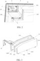
- a thermal insulation compartment module 2 is disposed at a refrigerating appliance 1. As shown in FIG. 2 , the thermal insulation compartment module 2 is disposed at an upper left corner of the refrigerating compartment 131.
- the thermal insulation compartment module 2 has a housing 20.
- the housing 20 includes a first housing unit 21 and a second housing unit 22.
- the first housing unit 21 and the second housing unit 22 are adjacent and are connected together to form an "L" shape.
- the first housing unit 21 extends in the height direction z of the refrigerating appliance to form a first wall portion 41.
- the first wall portion 41 includes a first inner housing 213 facing an accommodation compartment 3 and a first outer housing 214 facing the storage compartment 13.
- the second housing unit 22 extends in the transverse direction x of the refrigerating appliance to form a second wall portion 42.
- the second wall portion 42 includes a second inner housing 223 facing the accommodation compartment 3 and a second outer housing 224 facing the storage compartment 13.
- the first housing unit 21 When the thermal insulation compartment module 2 is joined to the inner wall 12 of the refrigerating compartment, the first housing unit 21 is connected to a top wall 121 and a rear wall 122 of the inner wall 12; and the second housing unit 22 is connected to a side wall 123 and the rear wall 122 of the inner wall 12. In this way, the first housing unit 21, the second housing unit 22, and at least a part of the inner wall 12 jointly form the accommodation compartment 3.
- a first buckle 2130 is disposed in the transverse direction x.
- a first side wall 2140 extends in the transverse direction x, and a first opening 2141 is provided in the first side wall 2140. The first buckle 2130 and the first opening 2141 are clamped together.
- a second buckle 2131 extends downward from an upper portion of the first inner housing 213.
- a bent wall 2142 extends upward on a side of the first outer housing 214 facing a first accommodating cavity 211 in the height direction z, and a second opening 2143 is provided in the bent wall 2142. The second buckle 2131 and the second opening 2143 are clamped together.
- the first inner housing 213 and the first outer housing 214 are fastened together by the foregoing two buckle connection structures, and are separated by an interval to define the first accommodating cavity 211.
- a first thermal insulation member 212 is arranged in the first accommodating cavity 211.
- the second inner housing 223 includes a second side wall 2230 extending downward in the height direction z, and a plurality of third openings 2231 are provided in the second side wall 2230.
- the second outer housing 224 includes a third side wall 2240 facing upward in the height direction z.
- a plurality of third buckles 2232 connected to the third openings 2231 are disposed on the third side wall 2240. The third openings and the third buckles are clamped together, to enable the second inner housing 223 and the second outer housing 224 to be fastened together.
- the second inner housing 223 and the second outer housing 224 are separated by an interval to define a second accommodating cavity 221.
- a second thermal insulation member 222 is arranged in the second accommodating cavity 221.
- accommodating cavities of a thermal insulation module are two independent cavity compartments, a shape and a structure are compact, so that a shape of the thermal insulation member is simplified, to help to improve matching between shapes and sizes of a thermal insulation member and an accommodating cavity, which is conducive to improving a thermal insulation effect.
- the second housing unit 22 includes a main wall 51 extending in the transverse direction x of the storage compartment 13.
- the second housing unit 22 further includes a boss 52 bent from the main wall 51 toward the top wall 121 of the storage compartment 13.
- the boss 52 is connected to a lower end portion of the first housing unit 21, and a connecting seam 60 is formed on a connection end surface between the two.
- a position of the connecting seam 60 is higher than a bottom wall 31 of the accommodation compartment 3, that is, higher than the second inner housing 223 of the second housing unit 22.
- the first wall portion 41 of the first housing unit 21 and the second wall portion 42 of the second housing unit 22 have different thicknesses.
- the thickness of the second wall portion 42 is smaller than the thickness of the first wall portion 41.
- different wall thicknesses may be selected according to different performance requirements, to ensure a good thermal insulation effect.
- connection end surface of the first housing unit 21 is a first stepped surface 81, and correspondingly a connection end surface of the second housing unit 22 is a second stepped surface 82.
- the two stepped surfaces 81, 82 are cooperatively connected to form a labyrinth-shaped connection structure 8, to increase the complexity of an air flow path, so that thermal exchange between the accommodation compartment and the storage compartment can be reduced.
- a height difference between the two stepped surfaces is not greater than 10 mm, preferably, 4 mm to 8 mm.
- the first outer housing 214 of the first housing unit 21 facing the storage compartment 13 and the second outer housing 224 of the second housing unit 22 facing the storage compartment 13 are located in a same plane in the height direction.
- the first inner housing 213 of the first housing unit 21 facing the accommodation compartment 3 and the second inner housing 223 of the second housing unit 22 facing the accommodation compartment 3 are located in a same plane in the height direction.
- connection block 501 extending in a first direction, that is, the height direction z of the storage compartment, and an insertion groove 502 is correspondingly formed in the second outer housing 224 and the second inner housing 223.
- the connection block 501 is inserted in the insertion groove 502 in the first direction, to form an insert structure 500.
- a plurality of groups of insert structures 500 are formed at the connection between the first housing unit 21 and the second housing unit 22.
- the insert structure 500 is located outside the first accommodating cavity 211 and the second accommodating cavity 221.
- the plurality of groups of insert structures 500 are arranged at intervals in a second direction, that is, the longitudinal direction y of the box body, to limit the first housing unit 21 and the second housing unit 22, which helps to implement that the first housing unit 21 and the second housing unit 22 are coplanar at the connection.
- an extending block 2147 protrudes from the first outer housing 214 in the height direction z.
- the extending block 2147 has a fourth opening 2146.
- a fourth buckle 2246 is disposed on the second outer housing 224 of the second housing unit 22. The fourth buckle 2246 is clamped with the fourth opening 2146 of the extending block 2147, to fasten the first housing unit 21 and the second housing unit 22.
- a support 7 is disposed in a direction of the accommodation compartment 3 toward an opening 33 in the storage compartment 13.
- the support 7 is approximately L-shaped.
- One end of the support 7 is connected to an end portion of the first housing unit 21 away from the connection between the first housing unit 21 and the second housing unit 22, that is, a position of the first housing unit 21 close to the top wall 121 of the storage compartment 13.
- the other end of the support 7 is connected to an end portion of the second housing unit 22 away from the connection between the first housing unit 21 and the second housing unit 22, that is, a position of the second housing unit close to the side wall 123 of the storage compartment 13.
- a first mounting hole 75 is provided at a position of the support 7 close to the first housing unit 21, and a fastening member S can pass through the first mounting hole 75 in the support 7 to be fastened to a first joint hole 1210 in the top wall 121 of the storage compartment 13.
- a joint wall 227 is disposed on the second inner housing of the second housing unit 22, and the joint wall 227 extends in the height direction z of the storage compartment.
- An open hole 226 is provided in the joint wall 227.
- a second mounting hole 73 in the support 7 and the open hole 226 in the joint wall 227 are fastened to a second joint hole 1230 in the inner wall 12 by the fastening member S.
- An end portion of the second outer housing 224 of the second housing unit 22 away from the opening in the storage compartment 13 is bent downward to form a side plate 200.
- One or more third mounting holes 201 are provided in the side plate 200.
- the fastening member S passes through the third mounting holes 201 in the second housing unit 22 to be fastened to a third joint hole 1220 in the inner wall 12.
- the support 7, the housing 20, and the inner wall 12 of the storage compartment 13 may be fixedly connected together, to form the accommodation compartment 3 of the thermal insulation compartment module 2.
- the thermal insulation compartment module 2 is located at an upper left corner of the storage compartment 13, and a seal member 100 is disposed between the housing 20 of the thermal insulation compartment module 2 and the inner wall 12 of the storage compartment 13.
- the seal member 100 may be made of a material such as sponge, rubber or silicone, to achieve good sealing between the accommodation compartment 3 and the storage compartment 13, thereby enhancing a thermal insulation effect.
Landscapes
- Engineering & Computer Science (AREA)
- Chemical & Material Sciences (AREA)
- Combustion & Propulsion (AREA)
- Physics & Mathematics (AREA)
- Mechanical Engineering (AREA)
- Thermal Sciences (AREA)
- General Engineering & Computer Science (AREA)
- Refrigerator Housings (AREA)
- Devices That Are Associated With Refrigeration Equipment (AREA)
Abstract
This application relates to a refrigerating appliance, including: a box body, including a storage compartment; and a thermal insulation compartment module, disposed in the storage compartment to define an accommodation compartment thermally insulated from the storage compartment, where the thermal insulation compartment module includes: a housing, having a first housing unit and a second housing unit, where a first thermal insulation member is located in a first accommodating cavity of the first housing unit, a second thermal insulation member is located in a second accommodating cavity of the second housing unit, and the first accommodating cavity is insulated from the second accommodating cavity, where one of the first housing unit and the second housing unit includes a first wall portion extending in a transverse direction of the storage compartment, the other one of the first housing unit and the second housing unit includes a second wall portion extending in a height direction of the storage compartment, and each of the first wall portion and the second wall portion defines a part of a boundary of the accommodation compartment. This application helps to improve matching between shapes and sizes of a thermal insulation member and an accommodating cavity, which is conducive to ensuring a thermal insulation effect
Description
- This application relates to the field of refrigerating appliances.
- At present, refrigerating appliances such as refrigerators are known and are used in everyday family life. To meet different requirements of consumers, a thermal insulation compartment module may be disposed in a refrigerating appliance, and the thermal insulation compartment module is disposed separately from a storage compartment. A thermal insulation wall usually needs to be disposed to avoid thermal exchange between the thermal insulation compartment module and the storage compartment, and a thermal insulation member is disposed in an accommodating cavity of the thermal insulation wall. In existing refrigerating appliances, a size and a shape of an accommodating cavity of a thermal insulation wall have a great impact on a size and a shape of a thermal insulation member, and at present the thermal insulation member may have nonuniform size or thickness distributions, leading to a reduced matching degree between the thermal insulation member and the accommodating cavity of the thermal insulation wall, which affects a thermal insulation effect.
- To overcome at least one technical problem above, an objective of embodiments of this application is to provide an improved refrigerating appliance.
- According to an embodiment of this application, a refrigerating appliance is provided, and includes: a box body, including a storage compartment; and a thermal insulation compartment module, disposed in the storage compartment to define an accommodation compartment thermally insulated from the storage compartment, where the thermal insulation compartment module includes: a housing, having a first housing unit and a second housing unit, where the first housing unit includes a first accommodating cavity and a first thermal insulation member located in the first accommodating cavity, the second housing unit includes a second accommodating cavity and a second thermal insulation member located in the second accommodating cavity, and the first accommodating cavity is insulated from the second accommodating cavity, where the first housing unit is connected to the second housing unit, one of the first housing unit and the second housing unit includes a first wall portion extending in a transverse direction of the storage compartment, the other one of the first housing unit and the second housing unit includes a second wall portion extending in a height direction of the storage compartment, and each of the first wall portion and the second wall portion defines a part of a boundary of the accommodation compartment.
- Because accommodating cavities of a thermal insulation module are two independent cavity compartments, a shape and a structure are compact, so that a shape of the thermal insulation member is simplified, to help to improve matching between shapes and sizes of a thermal insulation member and an accommodating cavity, which is conducive to improving a thermal insulation effect.
- According to an optional embodiment, the first housing unit, the second housing unit, and an inner wall of the storage compartment jointly define the accommodation compartment.
- According to an optional embodiment, the first housing unit is connected to an adjacent inner wall of the storage compartment, and the second housing unit is connected to an adjacent inner wall of the storage compartment.
- According to an optional embodiment, the first housing unit is connected to the second housing unit to form an L-shaped housing.
- According to an optional embodiment, at least one of the first housing unit and the second housing unit extends in only one of the height direction and the transverse direction of the storage compartment.
- According to an optional embodiment, one of the first housing unit and the second housing unit includes a main wall extending in one of the height direction and the transverse direction of the storage compartment and a boss that is bent from an end of the main wall to extend in the other one of the height direction and the transverse direction of the storage compartment, and the boss is connected to the other one of the first housing unit and the second housing unit.
- According to an optional embodiment, the boss extends in the height direction of the storage compartment to make a connecting seam between the first housing unit and the second housing unit higher than a bottom wall of the accommodation compartment.
- According to an optional embodiment, the first wall portion and the second wall portion have different thicknesses. According to an optional embodiment, the accommodation compartment has an opening that opens toward front of the storage compartment, the thermal insulation compartment module includes a support, and the support is respectively connected to the first housing unit and the second housing unit to jointly define the opening.
- According to an optional embodiment, the support is approximately L-shaped. According to an optional embodiment, one end of the support is connected to an end portion of the first housing unit away from a connection between the first housing unit and the second housing unit, and the other end of the support is connected to an end portion of the second housing unit away from the connection between the first housing unit and the second housing unit.
- According to an optional embodiment, the first housing unit includes a first inner housing facing the accommodation compartment, the second housing unit includes a second inner housing facing the accommodation compartment, one end of the support is fastened to the first inner housing, and the other end of the support is fastened to the second inner housing.
- According to an optional embodiment, opposite end surfaces at a connection between the first housing unit and the second housing unit form a labyrinth-shaped connection structure.
- According to an optional embodiment, the labyrinth-shaped connection structure includes at least two stepped surfaces. According to an optional embodiment, a height difference between the stepped surfaces is not greater than 10 mm.
- According to an optional embodiment, outer surfaces of the first housing unit and the second housing unit that are close to a position of a connection and face the storage compartment are located in a same plane.
- According to an optional embodiment, inner surfaces of the first housing unit and the second housing unit that are close to a position of a connection and face the accommodation compartment are located in a same plane.
- According to an optional embodiment, an outer surface of the first housing unit that faces the storage compartment has a first outer housing, an outer surface of the second housing unit that faces the storage compartment has a second outer housing, and the first outer housing and the second outer housing are coplanar.
- According to an optional embodiment, the first housing unit has a first inner housing facing the accommodation compartment, the second housing unit has a second inner housing facing the accommodation compartment, and the first inner housing and the second inner housing are coplanar.
- According to an optional embodiment, a first insert structure is provided at a connection between the first housing unit and the second housing unit to make one of the first housing unit and the second housing unit suitable for insertion with the other one of the first housing unit and the second housing unit in a first direction.
- According to an optional embodiment, the appliance includes at least two groups of first insert structures, where the at least two groups of first insert structures are arranged at intervals in a second direction perpendicular to the first direction.
- According to an optional embodiment, one of the at least two groups of first insert structures is arranged close to an inner surface of the housing, and the other one of the at least two groups of first insert structures is arranged close to an outer surface of the housing.
- According to an optional embodiment, the first insert structure is located outside the first accommodating cavity and the second accommodating cavity.
- According to an optional embodiment, the first insert structure includes a connection block disposed at one of connected opposite end surfaces of the first housing unit and the second housing unit and an insertion groove provided in the other one of the connected opposite end surfaces of the first housing unit and the second housing unit, and the connection block is inserted in the insertion groove in the first direction.
- In the following, the principles, features, and advantages of this application can be better understood by describing this application in more detail with reference to the accompanying drawings. The accompanying drawings include:
-
FIG. 1 is a three-dimensional view of a refrigerator according to an exemplary embodiment of this application; -
FIG. 2 is a three-dimensional view of a thermal insulation compartment module of a refrigerator according to an exemplary embodiment of this application; -
FIG. 3 is a three-dimensional exploded view of a first housing unit of a thermal insulation compartment module; -
FIG. 4 is a three-dimensional exploded view of a second housing unit of a thermal insulation compartment module; -
FIG. 5 is a cross-sectional view of a housing of a thermal insulation compartment module; -
FIG. 6 is a partial sectional view of a mark inFIG. 5 ; -
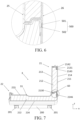
FIG. 7 is a cross-sectional view of a housing of a thermal insulation compartment module; -
FIG. 8 is a partial sectional view of a mark inFIG. 7 ; and -
FIG. 9 is a three-dimensional exploded view of a thermal insulation compartment module of a refrigerator according to an exemplary embodiment of this application. - Reference numerals:
1-refrigerating appliance; 2-thermal insulation compartment module; 3-accommodation compartment; 7-support; 8-labyrinth-shaped connection structure; 10-box body; 11-shell; 12-inner wall; 13-storage compartment; 20-housing; 21-first housing unit; 22-second housing unit; 25-inner surface; 26-outer surface; 31-bottom wall; 33-opening; 41-first wall portion; 42-second wall portion; 51-main wall; 52-boss; 60-connecting seam; 73-second mounting hole; 75-first mounting hole; 100-seal member; 121-top wall; 122-rear wall; 123-side wall; 131-refrigerating compartment; 132-freezing compartment; 200-side plate; 201-third mounting hole; 211-first accommodating cavity; 212-first thermal insulation member; 213-first inner housing; 214-first outer housing; 221-second accommodating cavity; 222-second thermal insulation member; 223-second inner housing; 224-second outer housing; 226-open hole; 227-joint wall; stepped surface-81,82; 500-first insert structure; 501-connection block; 502-insertion groove; 1210-first joint hole; 1220-third joint hole; 1230-second joint hole; 2130-first buckle; 2140-first side wall; 2141-first opening; 2131-second buckle; 2142-bent wall; 2143-second opening; 2146-fourth opening; 2147-extending block; 2230-second side wall; 2231-third opening; 2232-third buckle; 2240-third side wall; 2246-fourth buckle; A-separating wall; B-separating wall; x-transverse direction; y-longitudinal direction; and z-height direction. - Hereinafter, this application is further described in conjunction with the accompanying drawings and specific implementations, and it is to be noted that new embodiments may be formed by any combination between the embodiments described below or between various technical features without causing any conflict.
- In the description of this application, it should be understood that orientation or position relationships indicated by the terms such as "up", "down", "front", "rear", "height", "transverse", "horizontal", "inside", and "outside" are based on orientation or position relationships shown in the accompanying drawings, and are used only for ease and brevity of illustration and description, rather than indicating or implying that the mentioned apparatus or element needs to have a particular orientation or needs to be constructed and operated in a particular orientation. Therefore, such terms should not be construed as limiting of this application. In addition, the terms "first," "second," "third," "fourth," and the like are used to distinguish between similar elements, and these and other similar terms are not intended to limit the scope of this application.
- According to embodiments of this application, for clear description,
FIG. 1 shows an xyz coordinate system. A transverse direction x, a longitudinal direction y, and a height direction z that are perpendicular to each other two by two of a refrigerator in a conventional use state are schematically shown by arrows. - In an embodiment of this application, as shown in
FIG. 1 to FIG. 8 , a refrigerating appliance includes abox body 10, and thebox body 10 has ashell 11 and aninner wall 12. - The
inner wall 12 is disposed in theshell 11, and theinner wall 12 defines a plurality ofstorage compartments 13 that are open toward a front side. Eachstorage compartment 13 is separated by a separating wall A into a refrigeratingcompartment 131 and afreezing compartment 132. The refrigeratingcompartment 131 is located at an upper portion of thefreezing compartment 132. The separating wall A and a separating wall B may be used for blocking thermal exchange between the refrigeratingcompartment 131 and thefreezing compartment 132. - For the
freezing compartment 132, the separating wall B divides thefreezing compartment 132 into a left freezing compartment area and a right freezing compartment area. According to an embodiment of this application, a thermalinsulation compartment module 2 is disposed at a refrigeratingappliance 1. As shown inFIG. 2 , the thermalinsulation compartment module 2 is disposed at an upper left corner of the refrigeratingcompartment 131. - The thermal
insulation compartment module 2 has a housing 20. The housing 20 includes afirst housing unit 21 and asecond housing unit 22. Thefirst housing unit 21 and thesecond housing unit 22 are adjacent and are connected together to form an "L" shape. - The
first housing unit 21 extends in the height direction z of the refrigerating appliance to form afirst wall portion 41. Thefirst wall portion 41 includes a firstinner housing 213 facing anaccommodation compartment 3 and a firstouter housing 214 facing thestorage compartment 13. - The
second housing unit 22 extends in the transverse direction x of the refrigerating appliance to form asecond wall portion 42. Thesecond wall portion 42 includes a secondinner housing 223 facing theaccommodation compartment 3 and a secondouter housing 224 facing thestorage compartment 13. - When the thermal
insulation compartment module 2 is joined to theinner wall 12 of the refrigerating compartment, thefirst housing unit 21 is connected to atop wall 121 and arear wall 122 of theinner wall 12; and thesecond housing unit 22 is connected to aside wall 123 and therear wall 122 of theinner wall 12. In this way, thefirst housing unit 21, thesecond housing unit 22, and at least a part of theinner wall 12 jointly form theaccommodation compartment 3. - As shown in
FIG. 7 andFIG. 8 , at a lower portion of the firstinner housing 213, afirst buckle 2130 is disposed in the transverse direction x. At a lower portion of the firstouter housing 214, afirst side wall 2140 extends in the transverse direction x, and afirst opening 2141 is provided in thefirst side wall 2140. Thefirst buckle 2130 and thefirst opening 2141 are clamped together. - A
second buckle 2131 extends downward from an upper portion of the firstinner housing 213. Abent wall 2142 extends upward on a side of the firstouter housing 214 facing a firstaccommodating cavity 211 in the height direction z, and asecond opening 2143 is provided in thebent wall 2142. Thesecond buckle 2131 and thesecond opening 2143 are clamped together. - The first
inner housing 213 and the firstouter housing 214 are fastened together by the foregoing two buckle connection structures, and are separated by an interval to define the firstaccommodating cavity 211. A firstthermal insulation member 212 is arranged in the firstaccommodating cavity 211. - As shown in
FIG. 4 , the secondinner housing 223 includes asecond side wall 2230 extending downward in the height direction z, and a plurality ofthird openings 2231 are provided in thesecond side wall 2230. The secondouter housing 224 includes athird side wall 2240 facing upward in the height direction z. A plurality ofthird buckles 2232 connected to thethird openings 2231 are disposed on thethird side wall 2240. The third openings and the third buckles are clamped together, to enable the secondinner housing 223 and the secondouter housing 224 to be fastened together. - The second
inner housing 223 and the secondouter housing 224 are separated by an interval to define a secondaccommodating cavity 221. - A second
thermal insulation member 222 is arranged in the secondaccommodating cavity 221. - Because accommodating cavities of a thermal insulation module are two independent cavity compartments, a shape and a structure are compact, so that a shape of the thermal insulation member is simplified, to help to improve matching between shapes and sizes of a thermal insulation member and an accommodating cavity, which is conducive to improving a thermal insulation effect.
- As shown in
FIG. 5 , thesecond housing unit 22 includes amain wall 51 extending in the transverse direction x of thestorage compartment 13. Thesecond housing unit 22 further includes aboss 52 bent from themain wall 51 toward thetop wall 121 of thestorage compartment 13. - The
boss 52 is connected to a lower end portion of thefirst housing unit 21, and a connectingseam 60 is formed on a connection end surface between the two. A position of the connectingseam 60 is higher than abottom wall 31 of theaccommodation compartment 3, that is, higher than the secondinner housing 223 of thesecond housing unit 22. - The
first wall portion 41 of thefirst housing unit 21 and thesecond wall portion 42 of thesecond housing unit 22 have different thicknesses. In an embodiment of this application, the thickness of thesecond wall portion 42 is smaller than the thickness of thefirst wall portion 41. In this case, different wall thicknesses may be selected according to different performance requirements, to ensure a good thermal insulation effect. - The connection end surface of the
first housing unit 21 is a first steppedsurface 81, and correspondingly a connection end surface of thesecond housing unit 22 is a second steppedsurface 82. The two steppedsurfaces connection structure 8, to increase the complexity of an air flow path, so that thermal exchange between the accommodation compartment and the storage compartment can be reduced. - According to an embodiment of this application, a height difference between the two stepped surfaces is not greater than 10 mm, preferably, 4 mm to 8 mm.
- To improve the overall beauty of the housing 20 of the thermal
insulation compartment module 2, the firstouter housing 214 of thefirst housing unit 21 facing thestorage compartment 13 and the secondouter housing 224 of thesecond housing unit 22 facing thestorage compartment 13 are located in a same plane in the height direction. The firstinner housing 213 of thefirst housing unit 21 facing theaccommodation compartment 3 and the secondinner housing 223 of thesecond housing unit 22 facing theaccommodation compartment 3 are located in a same plane in the height direction. - To make the
first housing unit 21 and thesecond housing unit 22 coplanar at a connection for the beauty effect, at connected opposite end surfaces of thefirst housing unit 21 and thesecond housing unit 22, the firstouter housing 214 and the firstinner housing 213 form aconnection block 501 extending in a first direction, that is, the height direction z of the storage compartment, and aninsertion groove 502 is correspondingly formed in the secondouter housing 224 and the secondinner housing 223. Theconnection block 501 is inserted in theinsertion groove 502 in the first direction, to form aninsert structure 500. - A plurality of groups of
insert structures 500 are formed at the connection between thefirst housing unit 21 and thesecond housing unit 22. - The
insert structure 500 is located outside the firstaccommodating cavity 211 and the secondaccommodating cavity 221. - The plurality of groups of
insert structures 500 are arranged at intervals in a second direction, that is, the longitudinal direction y of the box body, to limit thefirst housing unit 21 and thesecond housing unit 22, which helps to implement that thefirst housing unit 21 and thesecond housing unit 22 are coplanar at the connection. - As shown in
FIG. 3 ,FIG. 7 , andFIG. 8 , at the connected opposite end surface of thefirst housing unit 21, an extendingblock 2147 protrudes from the firstouter housing 214 in the height direction z. The extendingblock 2147 has afourth opening 2146. Afourth buckle 2246 is disposed on the secondouter housing 224 of thesecond housing unit 22. Thefourth buckle 2246 is clamped with thefourth opening 2146 of the extendingblock 2147, to fasten thefirst housing unit 21 and thesecond housing unit 22. - A
support 7 is disposed in a direction of theaccommodation compartment 3 toward anopening 33 in thestorage compartment 13. Thesupport 7 is approximately L-shaped. One end of thesupport 7 is connected to an end portion of thefirst housing unit 21 away from the connection between thefirst housing unit 21 and thesecond housing unit 22, that is, a position of thefirst housing unit 21 close to thetop wall 121 of thestorage compartment 13. The other end of thesupport 7 is connected to an end portion of thesecond housing unit 22 away from the connection between thefirst housing unit 21 and thesecond housing unit 22, that is, a position of the second housing unit close to theside wall 123 of thestorage compartment 13. - A first mounting
hole 75 is provided at a position of thesupport 7 close to thefirst housing unit 21, and a fastening member S can pass through the first mountinghole 75 in thesupport 7 to be fastened to a firstjoint hole 1210 in thetop wall 121 of thestorage compartment 13. - A
joint wall 227 is disposed on the second inner housing of thesecond housing unit 22, and thejoint wall 227 extends in the height direction z of the storage compartment. Anopen hole 226 is provided in thejoint wall 227. - A second mounting
hole 73 in thesupport 7 and theopen hole 226 in thejoint wall 227 are fastened to a secondjoint hole 1230 in theinner wall 12 by the fastening member S. - An end portion of the second
outer housing 224 of thesecond housing unit 22 away from the opening in thestorage compartment 13 is bent downward to form aside plate 200. One or more third mountingholes 201 are provided in theside plate 200. The fastening member S passes through the third mountingholes 201 in thesecond housing unit 22 to be fastened to a thirdjoint hole 1220 in theinner wall 12. - In this case, the
support 7, the housing 20, and theinner wall 12 of thestorage compartment 13 may be fixedly connected together, to form theaccommodation compartment 3 of the thermalinsulation compartment module 2. - According to an embodiment of this application, as shown in
FIG. 8 , the thermalinsulation compartment module 2 is located at an upper left corner of thestorage compartment 13, and aseal member 100 is disposed between the housing 20 of the thermalinsulation compartment module 2 and theinner wall 12 of thestorage compartment 13. Theseal member 100 may be made of a material such as sponge, rubber or silicone, to achieve good sealing between theaccommodation compartment 3 and thestorage compartment 13, thereby enhancing a thermal insulation effect. - Although specific implementations have been described above, these implementations are not intended to limit the scope of this application, even if only one implementation is described with respect to specific features. The feature example provided in this application is intended to be illustrative rather than limiting, unless otherwise stated. During specific embodiment, a plurality of features may be combined with each other according to actual requirements and where technically feasible. In particular, features in different embodiments may also be combined with each other. Various substitutions, changes, and modifications may also be conceived without departing from the spirit and scope of this application.
Claims (15)
- A refrigerating appliance (1), comprising:a box body (10), comprising a storage compartment (13); anda thermal insulation compartment module (2), disposed in the storage compartment (13) to define an accommodation compartment (3) thermally insulated from the storage compartment, whereinthe thermal insulation compartment module (2) comprises:a housing (20), having a first housing unit (21) and a second housing unit (22), wherein the first housing unit (21) comprises a first accommodating cavity (211) and a first thermal insulation member (212) located in the first accommodating cavity (211), the second housing unit (22) comprises a second accommodating cavity (221) and a second thermal insulation member (222) located in the second accommodating cavity (221), and the first accommodating cavity (211) is insulated from the second accommodating cavity (221),wherein the first housing unit (21) is connected to the second housing unit (22), one of the first housing unit (21) and the second housing unit (22) comprises a first wall portion (41) extending in a transverse direction of the storage compartment (13), the other one of the first housing unit (21) and the second housing unit (22) comprises a second wall portion (42) extending in a height direction of the storage compartment (13), and each of the first wall portion (41) and the second wall portion (42) defines a part of a boundary of the accommodation compartment (3).
- The refrigerating appliance according to claim 1, characterized in that the first housing unit (21), the second housing unit (22), and an inner wall (12) of the storage compartment (13) jointly define the accommodation compartment (3); and/orthe first housing unit (21) is connected to an adjacent inner wall (12) of the storage compartment (13), and the second housing unit (22) is connected to an adjacent inner wall (12) of the storage compartment (13); and/orthe first housing unit (21) is connected to the second housing unit (22) to form an L-shaped housing (20).
- The refrigerating appliance according to claim 1, characterized in that at least one of the first housing unit (21) and the second housing unit (22) extends in only one of the height direction and the transverse direction of the storage compartment (13).
- The refrigerating appliance according to claim 1, characterized in that one of the first housing unit (21) and the second housing unit (22) comprises a main wall (51) extending in one of the height direction and the transverse direction of the storage compartment (13) and a boss (52) that is bent from an end of the main wall (51) to extend in the other one of the height direction and the transverse direction of the storage compartment (13), and the boss (52) is connected to the other one of the first housing unit (21) and the second housing unit (22).
- The refrigerating appliance according to claim 4, characterized in that the boss (52) extends in the height direction of the storage compartment (13) to make a connecting seam (60) between the first housing unit (21) and the second housing unit (22) higher than a bottom wall (31) of the accommodation compartment.
- The refrigerating appliance according to claim 1, characterized in that the first wall portion (41) and the second wall portion (42) have different thicknesses.
- The refrigerating appliance according to claim 1, characterized in that the accommodation compartment (3) has an opening (33) that opens toward front of the storage compartment (13), the thermal insulation compartment module (2) comprises a support (7), and the support (7) is respectively connected to the first housing unit (21) and the second housing unit (22) to jointly define the opening (33).
- The refrigerating appliance according to claim 7, characterized in thatthe support (7) is approximately L-shaped; and/orone end of the support (7) is connected to an end portion of the first housing unit (21) away from a connection between the first housing unit (21) and the second housing unit (22), and the other end of the support (7) is connected to an end portion of the second housing unit (22) away from the connection between the first housing unit (21) and the second housing unit (22); and/orthe first housing unit (21) comprises a first inner housing (213) facing the accommodation compartment (3), the second housing unit (22) comprises a second inner housing (223) facing the accommodation compartment (3), one end of the support (7) is fastened to the first inner housing (213), and the other end of the support (7) is fastened to the second inner housing (223).
- The refrigerating appliance according to claim 1, characterized in that opposite end surfaces at a connection between the first housing unit (21) and the second housing unit (22) form a labyrinth-shaped connection structure (8).
- The refrigerating appliance according to claim 9, characterized in that the labyrinth-shaped connection structure (8) comprises at least two stepped surfaces (81, 82).
- The refrigerating appliance according to claim 10, characterized in that a height difference between the stepped surfaces (81, 82) is not greater than 10 mm.
- The refrigerating appliance according to claim 1, characterized in thatouter surfaces of the first housing unit (21) and the second housing unit (22) that are close to a position of a connection and face the storage compartment (13) are located in a same plane; and/orinner surfaces of the first housing unit (21) and the second housing unit (22) that are close to a position of a connection and face the accommodation compartment (3) are located in a same plane; and/oran outer surface of the first housing unit (21) that faces the storage compartment (13) has a first outer housing (214), an outer surface of the second housing unit (22) that faces the storage compartment (13) has a second outer housing (224), and the first outer housing (214) and the second outer housing (224) are coplanar; and/orthe first housing unit (21) has a first inner housing (213) facing the accommodation compartment (3), the second housing unit (22) has a second inner housing (223) facing the accommodation compartment (3), and the first inner housing (213) and the second inner housing (223) are coplanar.
- The refrigerating appliance according to claim 1, characterized in that a first insert structure (500) is provided at a connection between the first housing unit (21) and the second housing unit (22) to make one of the first housing unit (21) and the second housing unit (22) suitable for insertion with the other one of the first housing unit (21) and the second housing unit (22) in a first direction.
- The refrigerating appliance according to claim 13, characterized by comprising at least two groups of first insert structures (500), wherein the at least two groups of first insert structures (500) are arranged at intervals in a second direction perpendicular to the first direction; and/or one of the at least two groups of first insert structures (500) is arranged close to an inner surface (25) of the housing (20), and the other one of the at least two groups of first insert structures (500) is arranged close to an outer surface (26) of the housing (20); and/or
the first insert structure (500) is located outside the first accommodating cavity (211) and the second accommodating cavity (221). - The refrigerating appliance according to claim 13, characterized in that the first insert structure (500) comprises a connection block (501) disposed at one of connected opposite end surfaces of the first housing unit (21) and the second housing unit (22) and an insertion groove (502) provided in the other one of the connected opposite end surfaces of the first housing unit (21) and the second housing unit (22), and the connection block (501) is inserted in the insertion groove (502) in the first direction.
Applications Claiming Priority (1)
| Application Number | Priority Date | Filing Date | Title |
|---|---|---|---|
| CN202320457938.0U CN219693638U (en) | 2023-03-08 | 2023-03-08 | Refrigerating appliance |
Publications (1)
| Publication Number | Publication Date |
|---|---|
| EP4428473A1 true EP4428473A1 (en) | 2024-09-11 |
Family
ID=87962612
Family Applications (1)
| Application Number | Title | Priority Date | Filing Date |
|---|---|---|---|
| EP24159897.8A Pending EP4428473A1 (en) | 2023-03-08 | 2024-02-27 | Refrigerating appliance |
Country Status (3)
| Country | Link |
|---|---|
| US (1) | US20240302095A1 (en) |
| EP (1) | EP4428473A1 (en) |
| CN (1) | CN219693638U (en) |
Families Citing this family (1)
| Publication number | Priority date | Publication date | Assignee | Title |
|---|---|---|---|---|
| US20250314419A1 (en) * | 2024-04-04 | 2025-10-09 | Hill Phoenix, Inc. | Insulation Panel Seal |
Citations (3)
| Publication number | Priority date | Publication date | Assignee | Title |
|---|---|---|---|---|
| CN106595172A (en) * | 2016-12-06 | 2017-04-26 | 海信容声(广东)冰箱有限公司 | Air cooling refrigerator provided with ice-making chamber |
| US20180087826A1 (en) * | 2016-09-28 | 2018-03-29 | Bsh Hausgeraete Gmbh | Domestic refrigerator having a locally thermally insulated outer enclosure of an ice-maker and method for producing a domestic refrigerator |
| CN112136013A (en) * | 2019-09-03 | 2020-12-25 | 海信容声(广东)冰箱有限公司 | A kind of refrigerator |
Family Cites Families (24)
| Publication number | Priority date | Publication date | Assignee | Title |
|---|---|---|---|---|
| US4044449A (en) * | 1975-02-07 | 1977-08-30 | Thomson-Brandt | Method of making refrigerating units and the like and product thereof |
| JPH07269779A (en) * | 1994-03-28 | 1995-10-20 | Toshiba Corp | Method for manufacturing heat insulating casing and vacuum heat insulating panel |
| US5875599A (en) * | 1995-09-25 | 1999-03-02 | Owens-Corning Fiberglas Technology Inc. | Modular insulation panels and insulated structures |
| JP3707657B2 (en) * | 1999-04-28 | 2005-10-19 | ホシザキ電機株式会社 | Heat insulation box |
| DE102004052622A1 (en) * | 2004-10-29 | 2006-06-08 | BSH Bosch und Siemens Hausgeräte GmbH | Modular refrigeration device |
| KR100700612B1 (en) * | 2006-01-03 | 2007-03-28 | 엘지전자 주식회사 | Combined structure of insulation panel of prefabricated refrigerator and prefabricated refrigerator having same |
| US20090095006A1 (en) * | 2007-10-12 | 2009-04-16 | Smith William C | Refrigeration compartment including freezer section |
| KR20130078531A (en) * | 2011-12-30 | 2013-07-10 | 삼성전자주식회사 | Refrigerator |
| KR101502112B1 (en) * | 2012-04-10 | 2015-03-13 | 삼성전자 주식회사 | Refrigerator And Manufacturing Method Thereof |
| CN103673453B (en) * | 2012-09-22 | 2018-10-19 | 博西华家用电器有限公司 | Refrigeration appliance |
| KR20150061672A (en) * | 2013-11-27 | 2015-06-05 | 삼성전자주식회사 | Curd maker and refrigerator having the same |
| KR101798536B1 (en) * | 2016-04-08 | 2017-11-17 | 동부대우전자 주식회사 | Refrigerator |
| DE102016218644A1 (en) * | 2016-09-28 | 2018-03-29 | BSH Hausgeräte GmbH | Domestic refrigerator with a multi-part outer casing of an icemaker |
| KR20190125119A (en) * | 2018-04-27 | 2019-11-06 | 주식회사 위니아대우 | Ice maker and refrigerator having same |
| CN112601922B (en) * | 2018-08-31 | 2022-05-17 | 三星电子株式会社 | refrigerator |
| US11761700B2 (en) * | 2018-11-28 | 2023-09-19 | Bsh Hausgeraete Gmbh | Household refrigeration apparatus having an ice maker with a specific seal |
| US20200166271A1 (en) * | 2018-11-28 | 2020-05-28 | Bsh Hausgeraete Gmbh | Ice maker with specific seal and household refrigeration apparatus |
| DE102019213447A1 (en) * | 2019-09-04 | 2021-03-04 | BSH Hausgeräte GmbH | Refrigeration device |
| US11566837B2 (en) * | 2019-10-22 | 2023-01-31 | Bsh Hausgeraete Gmbh | Home appliance device and method for assembling the home appliance device |
| WO2021125883A1 (en) * | 2019-12-20 | 2021-06-24 | 삼성전자주식회사 | Apparatus for producing dairy products, and refrigerator including same |
| KR20210080197A (en) * | 2019-12-20 | 2021-06-30 | 삼성전자주식회사 | Dairy products maker and refrigerator having the same |
| US20220065520A1 (en) * | 2020-08-31 | 2022-03-03 | Keter Plastic Ltd. | Cooler container |
| CN214537056U (en) * | 2020-10-21 | 2021-10-29 | 博西华电器(江苏)有限公司 | Refrigeration device with lighting module |
| KR102338214B1 (en) * | 2021-07-16 | 2021-12-10 | 윤상길 | Heat radiation door lamp system for cold storage |
-
2023
- 2023-03-08 CN CN202320457938.0U patent/CN219693638U/en active Active
-
2024
- 2024-02-27 EP EP24159897.8A patent/EP4428473A1/en active Pending
- 2024-03-06 US US18/597,241 patent/US20240302095A1/en active Pending
Patent Citations (3)
| Publication number | Priority date | Publication date | Assignee | Title |
|---|---|---|---|---|
| US20180087826A1 (en) * | 2016-09-28 | 2018-03-29 | Bsh Hausgeraete Gmbh | Domestic refrigerator having a locally thermally insulated outer enclosure of an ice-maker and method for producing a domestic refrigerator |
| CN106595172A (en) * | 2016-12-06 | 2017-04-26 | 海信容声(广东)冰箱有限公司 | Air cooling refrigerator provided with ice-making chamber |
| CN112136013A (en) * | 2019-09-03 | 2020-12-25 | 海信容声(广东)冰箱有限公司 | A kind of refrigerator |
Also Published As
| Publication number | Publication date |
|---|---|
| CN219693638U (en) | 2023-09-15 |
| US20240302095A1 (en) | 2024-09-12 |
Similar Documents
| Publication | Publication Date | Title |
|---|---|---|
| US6266970B1 (en) | Vertical partition cover assembly of side-by-side type refrigerator | |
| CN107110593B (en) | Refrigerator and vacuum heat insulation plate thereof | |
| KR102273285B1 (en) | Refrigerator and vacuum insulation module thereof | |
| KR200264494Y1 (en) | Front central part of refrigerator | |
| TWI477728B (en) | Refrigerator | |
| TW201312069A (en) | Refrigerator | |
| CN102645068A (en) | Air duct component and refrigerator with same | |
| TWI529360B (en) | Refrigerator | |
| CN112601922A (en) | Refrigerator with a door | |
| CN218495561U (en) | Baffle assembly and refrigeration equipment | |
| US20240302095A1 (en) | Refrigerating appliance | |
| CN109695980A (en) | Ice making evaporator compartment and refrigerator with it | |
| CN113348334B (en) | Refrigerator with a door | |
| CN111351285B (en) | Horizontal refrigerator | |
| JPH08152254A (en) | Refrigerator with deep freezer | |
| KR100341557B1 (en) | Refrigerator | |
| JP2019138532A (en) | refrigerator | |
| JP2018031571A (en) | refrigerator | |
| CN114508888A (en) | Refrigerator with a door | |
| CN218065498U (en) | refrigerator | |
| JP2021050910A (en) | refrigerator | |
| CN221122630U (en) | Air duct components and refrigerators | |
| CN221122650U (en) | Refrigeration equipment | |
| CN218764200U (en) | Foaming component and refrigeration equipment | |
| CN120333010A (en) | Refrigeration equipment |
Legal Events
| Date | Code | Title | Description |
|---|---|---|---|
| PUAI | Public reference made under article 153(3) epc to a published international application that has entered the european phase |
Free format text: ORIGINAL CODE: 0009012 |
|
| STAA | Information on the status of an ep patent application or granted ep patent |
Free format text: STATUS: THE APPLICATION HAS BEEN PUBLISHED |
|
| AK | Designated contracting states |
Kind code of ref document: A1 Designated state(s): AL AT BE BG CH CY CZ DE DK EE ES FI FR GB GR HR HU IE IS IT LI LT LU LV MC ME MK MT NL NO PL PT RO RS SE SI SK SM TR |
|
| STAA | Information on the status of an ep patent application or granted ep patent |
Free format text: STATUS: REQUEST FOR EXAMINATION WAS MADE |
|
| 17P | Request for examination filed |
Effective date: 20250311 |