EP4428467A1 - Heat pump unit comprising an electrical box - Google Patents
Heat pump unit comprising an electrical box Download PDFInfo
- Publication number
- EP4428467A1 EP4428467A1 EP23161310.0A EP23161310A EP4428467A1 EP 4428467 A1 EP4428467 A1 EP 4428467A1 EP 23161310 A EP23161310 A EP 23161310A EP 4428467 A1 EP4428467 A1 EP 4428467A1
- Authority
- EP
- European Patent Office
- Prior art keywords
- heat pump
- electrical
- pump unit
- access points
- terminal block
- Prior art date
- Legal status (The legal status is an assumption and is not a legal conclusion. Google has not performed a legal analysis and makes no representation as to the accuracy of the status listed.)
- Withdrawn
Links
Images
Classifications
-
- F—MECHANICAL ENGINEERING; LIGHTING; HEATING; WEAPONS; BLASTING
- F24—HEATING; RANGES; VENTILATING
- F24H—FLUID HEATERS, e.g. WATER OR AIR HEATERS, HAVING HEAT-GENERATING MEANS, e.g. HEAT PUMPS, IN GENERAL
- F24H9/00—Details
- F24H9/02—Casings; Cover lids; Ornamental panels
-
- F—MECHANICAL ENGINEERING; LIGHTING; HEATING; WEAPONS; BLASTING
- F24—HEATING; RANGES; VENTILATING
- F24F—AIR-CONDITIONING; AIR-HUMIDIFICATION; VENTILATION; USE OF AIR CURRENTS FOR SCREENING
- F24F1/00—Room units for air-conditioning, e.g. separate or self-contained units or units receiving primary air from a central station
- F24F1/06—Separate outdoor units, e.g. outdoor unit to be linked to a separate room comprising a compressor and a heat exchanger
- F24F1/56—Casing or covers of separate outdoor units, e.g. fan guards
-
- F—MECHANICAL ENGINEERING; LIGHTING; HEATING; WEAPONS; BLASTING
- F24—HEATING; RANGES; VENTILATING
- F24F—AIR-CONDITIONING; AIR-HUMIDIFICATION; VENTILATION; USE OF AIR CURRENTS FOR SCREENING
- F24F11/00—Control or safety arrangements
- F24F11/88—Electrical aspects, e.g. circuits
-
- F—MECHANICAL ENGINEERING; LIGHTING; HEATING; WEAPONS; BLASTING
- F24—HEATING; RANGES; VENTILATING
- F24F—AIR-CONDITIONING; AIR-HUMIDIFICATION; VENTILATION; USE OF AIR CURRENTS FOR SCREENING
- F24F11/00—Control or safety arrangements
- F24F11/89—Arrangement or mounting of control or safety devices
-
- F—MECHANICAL ENGINEERING; LIGHTING; HEATING; WEAPONS; BLASTING
- F24—HEATING; RANGES; VENTILATING
- F24H—FLUID HEATERS, e.g. WATER OR AIR HEATERS, HAVING HEAT-GENERATING MEANS, e.g. HEAT PUMPS, IN GENERAL
- F24H4/00—Fluid heaters characterised by the use of heat pumps
-
- F—MECHANICAL ENGINEERING; LIGHTING; HEATING; WEAPONS; BLASTING
- F24—HEATING; RANGES; VENTILATING
- F24H—FLUID HEATERS, e.g. WATER OR AIR HEATERS, HAVING HEAT-GENERATING MEANS, e.g. HEAT PUMPS, IN GENERAL
- F24H9/00—Details
- F24H9/20—Arrangement or mounting of control or safety devices
-
- F—MECHANICAL ENGINEERING; LIGHTING; HEATING; WEAPONS; BLASTING
- F24—HEATING; RANGES; VENTILATING
- F24F—AIR-CONDITIONING; AIR-HUMIDIFICATION; VENTILATION; USE OF AIR CURRENTS FOR SCREENING
- F24F1/00—Room units for air-conditioning, e.g. separate or self-contained units or units receiving primary air from a central station
- F24F1/06—Separate outdoor units, e.g. outdoor unit to be linked to a separate room comprising a compressor and a heat exchanger
- F24F1/20—Electric components for separate outdoor units
Definitions
- the invention relates to a heat pump unit comprising an electrical box.
- the invention further relates to an electrical box for a heat pump unit.
- the electrical box comprising an electrical terminal block, connected or connectable to one or more electrical cables, one or more internal access points and one or more external access points. Both the internal and external access points may be used for one or more electrical cables to run through either access points to reach at least one connection point outside the product. This offers two modes of electrical connection on the same product for the installation of the heat pump unit.
- Heat pump units require a power supply to operate. They may also require a wired connection between the indoor unit and the outdoor heat pump unit for control and monitoring purposes, i.e. to transmit control signal or sensor signals.
- connections are usually made by one or more electrical cables connected from the building serviced by the heat pump unit to an electrical box comprised by the outdoor or indoor heat pump unit.
- the connections are preferably well covered and preferably inaccessible to reduce safety risks or risks of damaging these connections, as users or by-passer can't easily or accidentally reach the connections, with all associated risks like hot spots, chemical risks, electrical risks.
- an enclosure may be provided on an external surface of the heat pump unit.
- the enclosure may comprise a box and a cover to close/open the box.
- the cover is removed. This provides access to the electrical terminal block positioned inside the box. The electrical connections are made and the cover is then replaced to cover the enclosure and the electrical connections.
- openings are provided in a side panel of the heat pump unit through which cables can be inserted into the inside of the heat pump unit. These openings can be fitted with flexible material to ensure a seal between the cable and the panel. Once the cables are inserted into the product, they are connected to an electrical terminal block inside the heat pump the unit.
- connections should not be passed through the side of the heat pump unit for safety reasons.
- a solution would be to pass the connections via the inside of the heat pump unit, for example through the bottom of the heat pump unit.
- not all installation locations permit the pass-through at the bottom. In such cases, a connection through the side may be necessary.
- the object is therefore to provide a heat pump unit which can be connected to at least one connection point outside of the product while offering the flexibility of passing the connections through either, at least a part of, the inside or via the outside of the heat pump unit, such as via a bottom or a side of the heat pump unit.
- a heat pump unit comprising a heat pump housing defining an inner space and heat pump components positioned in the inner space
- the heat pump unit comprises an electrical box, the electrical box comprising an electrical terminal block, connected or connectable to one or more electrical cables
- the electrical box comprises one or more internal access points positioned inside the heat pump housing for one or more electrical cables to run from the electrical terminal block to at least one connection point located outside of the heat pump unit while passing at least partially through the inner space of the heat pump housing, and one or more external access points positioned outside the heat pump housing for one or more electrical cables to run from the electrical terminal block to at least one connection point located outside of the heat pump unit while passing only through the outer space of the heat pump housing
- the electrical box is preferably positioned in a panel opening in a side panel of the heat pump housing, such as a back side panel, the panel opening being configured to accommodate the electrical box.
- the electrical box is preferably positioned in the panel opening in a watertight manner. Positioning and sealing may be achieved by pressing the electrical box partially through the panel opening.
- the panel opening and the electrical box form a tight fit, to secure the electrical box in position and prevent water or dirt from entering the heat pump housing. This can be achieved by a fixed material, a flexible area, such as a seal.
- the electrical box may have a circumferential notch in which the inner edge of the opening in the side panel is captured.
- the notch may be provided in the housing part, the cover part or on the interface of these parts. The housing and cover part are explained in more detail below. This way the electrical box can be fixed by pressing the electrical box through the opening until the notch captures the inner edge, locking the electrical box in position.
- the notch may be made from a flexible material to allow capturing the edge of the opening when inserted inside the notch.
- the heat pump components may be, amongst others, a compressor, a fan, a condenser, an expansion valve and/or an evaporator.
- the electrical box comprises a housing part comprising the one or more internal access points and a cover part comprising the one or more external access points.
- the housing part is (mainly) positioned inside the heat pump housing and the cover part is (mainly) positioned outside the heat pump housing.
- the housing part and the cover part are preferably matching and configured to connect to each other to form the electrical box.
- the housing part may be fixed to the heat pump housing and the cover part may be removable from the housing part to provide access to the electrical terminal block.
- the cover part is positioned on the outside of the heat pump housing, thereby advantageously providing access to the inside of the electrical box and the electrical terminal block from the outside of the heat pump unit.
- the cover part is configured to be locked to and unlocked from the housing part and/or the heat pump housing with a tool.
- the cover part may be locked and unlocked using a reversible locking means such as screws.
- the locking and unlocking tool may be a screwdriver.
- Opening the cover part preferably requires special, non-conventional tooling or a key. This ensures only authorized people may gain access to the inside of the electrical box, such as qualified maintenance staff.
- An additional layer may be added over the cover as to further protect or hide the electrical box and, at least partially the one or electrical cables.
- the additional layer may be shaped in such a manner to guide water such as rain water off of the electrical box and away from the heat pump unit.
- the one or more internal access points and/or the one or more external access points are formed as openings or openable members.
- Openable members may be formed as removable pre-cut members. This embodiment has the advantage that openings which are not used can remain closed. This is particularly advantageous for the one or more external access points, as if these can be kept closed, the ingress of water via the external access points can be prevented.
- the one or more internal access points and/or the one or more external access points are positioned below the electrical terminal block.
- the one or more internal access points and/or the one or more external access points are positioned at least 40mm lower than the electrical terminal block.
- the access points are positioned at least 40mm, preferably at least 70mm, lower than the lowest connection point of the electrical terminal block.
- the access points are preferably made at the bottom of the electrical box.
- the terms lower and vertical are used with reference to the normal operating orientation of the heat pump unit.
- the heat pump housing may for instance comprise one or more supports or legs on which the heat pump unit stands, thereby defining the up and downward direction.
- the heat pump unit comprises one or more electrical cables connected to the electrical terminal block, the electrical cables being power supply cables and/or signal cables.
- Power cables are used to provide the heat pump unit and in particular the heat pump components of the heat pump unit with electricity.
- Signal cables are used to convey control signals and/or sensor readings to or from the heat pump unit.
- the electrical cables have a first diameter and the internal and external access points have a second diameter or a minimal cross-sectional width in the range of 1 to 3 times the first diameter.
- the electrical box comprises outlet openings positioned above the electrical terminal block for electrical cables to run between the electrical terminal block and one or more of the heat pump components.
- the heat pump unit is an outdoor heat pump unit.
- the heat pump housing comprises a bottom panel having at least one hole.
- the electrical cables running from the electrical terminal block to at least one connection point located outside of the heat pump unit while passing at least partially in the inner space of the heat pump housing pass through the at least one hole in the bottom panel.
- an electrical box for a heat pump unit comprising a heat pump housing, the electrical box comprising an electrical terminal block, connected or connectable to one or more electrical cables, wherein the electrical box comprises one or more internal access points for one or more electrical cables to run from the electrical terminal block to a connection point located outside of the heat pump unit while passing at least partially through the inner space of the heat pump housing and one or more external access points for one or more electrical cables to from the electrical terminal block to a connection point located outside of the heat pump unit while passing only through the outer space of the heat pump housing.
- the electrical box is configured to be positioned in an opening of the heat pump housing with the internal access points positioned inside the heat pump housing and the external access points positioned outside the heat pump housing.
- the electrical box may have a circumferential notch that is configured to receive an edge of an opening in the heat pump housing, i.e. in a side panel, to secure position the electrical box in the opening of the heat pump housing.
- the notch may be provided in the housing part, the cover part or on the interface of these parts.
- the dimensions of the electrical box may be larger than on the side of the notch of the internal access points. This allows the electrical box to be positioned in the opening in the heat pump housing from the outside, while preventing the electrical box from being inserted too far.
- the notch may be made from a flexible material to allow capturing the edge of the opening when inserted inside the notch.
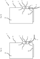
- FIGS 1a and 1b schematically show a heat pump unit 1 comprising a heat pump housing 10 defining an inner space having heat pump components, not shown, positioned within the inner space.
- the heat pump unit 1 comprises an electrical box 2, attached to a back panel 11, having an electrical terminal block 5 connected to one or more electrical cables 6 which terminate at a connection point anywhere outside the heat pump unit.
- the electrical box 2 comprises one or more internal access points 8 positioned inside the heat pump housing 10.
- the electrical box 2 further comprises one or more external access points 7 positioned outside the heat pump housing 10.
- the electrical box 2 comprises outlet openings 9 positioned above the electrical terminal block 5 for electrical cables to run between the electrical terminal block 5 and one or more of the heat pump components, not shown.
- the one or more electrical cables 6 are connect to the electrical terminal block 5 while running through the one or more external access points 7 positioned outside the heat pump housing 10.
- the one or more electrical cables 6 are connect to the electrical terminal block 5, while running through the one or more internal access points 8 positioned inside the heat pump housing 10, to terminate at a connection point anywhere outside the heat pump unit.
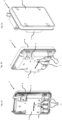
- Figures 2a to 2d show different views of an electrical box 2 for a heat pump unit 1, not shown in these figures, comprising a housing part 3, a cover part 4, multiple external access points 7, multiple internal access points 8, and an outlet opening 9.
- an electrical terminal block 5 is present but not shown between the housing part 3 and the cover part 4.
- the electrical box 2 is shown from the bottom side wherein the electrical box 2 is attached to a back panel 11 of a heat pump unit 1, not shown.
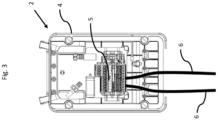
- FIG 3 shows another view of the electrical box 2 as shown in Figures 2a to 2d .
- housing part 3 is omitted and an electrical terminal block 5 can be clearly seen.
- two electrical cables 6 are shown and connected to the electrical terminal block 5.
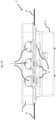
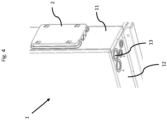
- Figure 4 schematically shows a part of a heat pump unit 1 wherein the bottom panel 12 of the heat pump housing 10 comprises multiple holes (13) to enable the pass-through of electrical cables 6 while the electrical box 2 is attached to the back panel 11.
Landscapes
- Engineering & Computer Science (AREA)
- Chemical & Material Sciences (AREA)
- Combustion & Propulsion (AREA)
- Mechanical Engineering (AREA)
- General Engineering & Computer Science (AREA)
- Physics & Mathematics (AREA)
- Thermal Sciences (AREA)
- Details Of Reciprocating Pumps (AREA)
Abstract
The invention relates to a heat pump unit comprising an electrical box. The invention further relates to an electrical box for a heat pump unit. The electrical box comprising an electrical terminal block, connected or connectable to one or more electrical cables, one or more internal access points and one or more external access points. Both the internal and external access points may be used for one or more electrical cables to run through either access points to reach at least one connection point outside the product. This offers two modes of electrical connection on the same product.
Description
- The invention relates to a heat pump unit comprising an electrical box. The invention further relates to an electrical box for a heat pump unit. The electrical box comprising an electrical terminal block, connected or connectable to one or more electrical cables, one or more internal access points and one or more external access points. Both the internal and external access points may be used for one or more electrical cables to run through either access points to reach at least one connection point outside the product. This offers two modes of electrical connection on the same product for the installation of the heat pump unit.
- Heat pump units require a power supply to operate. They may also require a wired connection between the indoor unit and the outdoor heat pump unit for control and monitoring purposes, i.e. to transmit control signal or sensor signals.
- These connections are usually made by one or more electrical cables connected from the building serviced by the heat pump unit to an electrical box comprised by the outdoor or indoor heat pump unit.
- To make the heat pump unit connections, including electrical connections as described above and fluid connections, the connections are preferably well covered and preferably inaccessible to reduce safety risks or risks of damaging these connections, as users or by-passer can't easily or accidentally reach the connections, with all associated risks like hot spots, chemical risks, electrical risks.
- Different solutions are known to provide such electrical connections in a reliable manner.
- For instance, an enclosure may be provided on an external surface of the heat pump unit. The enclosure may comprise a box and a cover to close/open the box. When electrical connections are to be made, the cover is removed. This provides access to the electrical terminal block positioned inside the box. The electrical connections are made and the cover is then replaced to cover the enclosure and the electrical connections.
- According to an alternative solution, openings are provided in a side panel of the heat pump unit through which cables can be inserted into the inside of the heat pump unit. These openings can be fitted with flexible material to ensure a seal between the cable and the panel. Once the cables are inserted into the product, they are connected to an electrical terminal block inside the heat pump the unit.
- These solutions aim to prevent access to the electrical terminal block by users, fingers, particles, animals etc. These solutions also aim to prevent water from reaching the electrical terminal block.
- Preferably, the connections should not be passed through the side of the heat pump unit for safety reasons. A solution would be to pass the connections via the inside of the heat pump unit, for example through the bottom of the heat pump unit. However, not all installation locations permit the pass-through at the bottom. In such cases, a connection through the side may be necessary.
- The object is therefore to provide a heat pump unit which can be connected to at least one connection point outside of the product while offering the flexibility of passing the connections through either, at least a part of, the inside or via the outside of the heat pump unit, such as via a bottom or a side of the heat pump unit.
- The object is solved by a heat pump unit comprising a heat pump housing defining an inner space and heat pump components positioned in the inner space, wherein the heat pump unit comprises an electrical box, the electrical box comprising an electrical terminal block, connected or connectable to one or more electrical cables, wherein the electrical box comprises one or more internal access points positioned inside the heat pump housing for one or more electrical cables to run from the electrical terminal block to at least one connection point located outside of the heat pump unit while passing at least partially through the inner space of the heat pump housing, and one or more external access points positioned outside the heat pump housing for one or more electrical cables to run from the electrical terminal block to at least one connection point located outside of the heat pump unit while passing only through the outer space of the heat pump housing
- This offers two modes of electrical connection on the same product: with the wire(s) directly from the outside of the heat pump unit or by running the wire(s), at least partially, through the inside of the heat pump unit. Two modes of installation of the heat pump unit are provided without the need to change components and without bringing any inconvenience to either installation.
- For both modes the problems of permeability of solid and liquid particles (progression index) can be dealt with. The definition of positions, geometries and distances, as explained in more detail below, makes it possible to prevent the projection of particles and solids and in particular to expect an IP44 type of ingress protection according to the IEC 60529 standard which is a known standard that determines the degree of protection provided by the enclosure of electrical equipment.
- The electrical box is preferably positioned in a panel opening in a side panel of the heat pump housing, such as a back side panel, the panel opening being configured to accommodate the electrical box. The electrical box is preferably positioned in the panel opening in a watertight manner. Positioning and sealing may be achieved by pressing the electrical box partially through the panel opening. The panel opening and the electrical box form a tight fit, to secure the electrical box in position and prevent water or dirt from entering the heat pump housing. This can be achieved by a fixed material, a flexible area, such as a seal.
- The electrical box may have a circumferential notch in which the inner edge of the opening in the side panel is captured. The notch may be provided in the housing part, the cover part or on the interface of these parts. The housing and cover part are explained in more detail below. This way the electrical box can be fixed by pressing the electrical box through the opening until the notch captures the inner edge, locking the electrical box in position. The notch may be made from a flexible material to allow capturing the edge of the opening when inserted inside the notch.
- The heat pump components may be, amongst others, a compressor, a fan, a condenser, an expansion valve and/or an evaporator.
- According to an embodiment the electrical box comprises a housing part comprising the one or more internal access points and a cover part comprising the one or more external access points.
- The housing part is (mainly) positioned inside the heat pump housing and the cover part is (mainly) positioned outside the heat pump housing. The housing part and the cover part are preferably matching and configured to connect to each other to form the electrical box. The housing part may be fixed to the heat pump housing and the cover part may be removable from the housing part to provide access to the electrical terminal block.
- The cover part is positioned on the outside of the heat pump housing, thereby advantageously providing access to the inside of the electrical box and the electrical terminal block from the outside of the heat pump unit.
- According to an embodiment the cover part is configured to be locked to and unlocked from the housing part and/or the heat pump housing with a tool. The cover part may be locked and unlocked using a reversible locking means such as screws. As such, the locking and unlocking tool may be a screwdriver.
- Opening the cover part preferably requires special, non-conventional tooling or a key. This ensures only authorized people may gain access to the inside of the electrical box, such as qualified maintenance staff.
- An additional layer may be added over the cover as to further protect or hide the electrical box and, at least partially the one or electrical cables. The additional layer may be shaped in such a manner to guide water such as rain water off of the electrical box and away from the heat pump unit.
- According to an embodiment the one or more internal access points and/or the one or more external access points are formed as openings or openable members.
- Openable members may be formed as removable pre-cut members. This embodiment has the advantage that openings which are not used can remain closed. This is particularly advantageous for the one or more external access points, as if these can be kept closed, the ingress of water via the external access points can be prevented.
- According to an embodiment the one or more internal access points and/or the one or more external access points are positioned below the electrical terminal block.
- According to an embodiment the one or more internal access points and/or the one or more external access points are positioned at least 40mm lower than the electrical terminal block.
- The access points are positioned at least 40mm, preferably at least 70mm, lower than the lowest connection point of the electrical terminal block. The access points are preferably made at the bottom of the electrical box.
- This distance prevents water from splashing in and reaching the electrical terminal block, thus enabling compliance with the IP44 rating according to the IEC 60529 standard.
- The terms lower and vertical are used with reference to the normal operating orientation of the heat pump unit. The heat pump housing may for instance comprise one or more supports or legs on which the heat pump unit stands, thereby defining the up and downward direction.
- According to an embodiment the heat pump unit comprises one or more electrical cables connected to the electrical terminal block, the electrical cables being power supply cables and/or signal cables.
- Power cables are used to provide the heat pump unit and in particular the heat pump components of the heat pump unit with electricity. Signal cables are used to convey control signals and/or sensor readings to or from the heat pump unit.
- According to an embodiment the electrical cables have a first diameter and the internal and external access points have a second diameter or a minimal cross-sectional width in the range of 1 to 3 times the first diameter.
- According to an embodiment the electrical box comprises outlet openings positioned above the electrical terminal block for electrical cables to run between the electrical terminal block and one or more of the heat pump components.
- According to an embodiment the heat pump unit is an outdoor heat pump unit.
- According to an embodiment, the heat pump housing comprises a bottom panel having at least one hole.
- According to an embodiment the electrical cables running from the electrical terminal block to at least one connection point located outside of the heat pump unit while passing at least partially in the inner space of the heat pump housing pass through the at least one hole in the bottom panel.
- According to a further aspect there is provided an electrical box for a heat pump unit comprising a heat pump housing, the electrical box comprising an electrical terminal block, connected or connectable to one or more electrical cables, wherein the electrical box comprises one or more internal access points for one or more electrical cables to run from the electrical terminal block to a connection point located outside of the heat pump unit while passing at least partially through the inner space of the heat pump housing and one or more external access points for one or more electrical cables to from the electrical terminal block to a connection point located outside of the heat pump unit while passing only through the outer space of the heat pump housing.
- According to an embodiment the electrical box is configured to be positioned in an opening of the heat pump housing with the internal access points positioned inside the heat pump housing and the external access points positioned outside the heat pump housing.
- The electrical box may have a circumferential notch that is configured to receive an edge of an opening in the heat pump housing, i.e. in a side panel, to secure position the electrical box in the opening of the heat pump housing. The notch may be provided in the housing part, the cover part or on the interface of these parts. On the side of the notch of the external access points the dimensions of the electrical box may be larger than on the side of the notch of the internal access points. This allows the electrical box to be positioned in the opening in the heat pump housing from the outside, while preventing the electrical box from being inserted too far. On the side of the notch of the internal access points the dimensions may be slightly larger than the opening of the heat pump housing, creating a tight fit when installed. The notch may be made from a flexible material to allow capturing the edge of the opening when inserted inside the notch.
- In the figures, the subject-matter of the invention is schematically shown, wherein identical or similarly acting elements are usually provided with the same reference signs.
- Figures 1a-b
- schematically show a view of a heat pump unit according to an embodiment,
- Figures 2a-d
- schematically show different views of an electrical box according to an embodiment,
- Figure 3
- schematically shows a view of an electrical box according to an embodiment,
- Figure 4
- schematically shows another view of a heat pump unit according to an embodiment
-
Figures 1a and 1b schematically show aheat pump unit 1 comprising aheat pump housing 10 defining an inner space having heat pump components, not shown, positioned within the inner space. Theheat pump unit 1 comprises anelectrical box 2, attached to aback panel 11, having an electricalterminal block 5 connected to one or moreelectrical cables 6 which terminate at a connection point anywhere outside the heat pump unit. Theelectrical box 2 comprises one or moreinternal access points 8 positioned inside theheat pump housing 10. Theelectrical box 2 further comprises one or moreexternal access points 7 positioned outside theheat pump housing 10. Furthermore, theelectrical box 2 comprisesoutlet openings 9 positioned above the electricalterminal block 5 for electrical cables to run between the electricalterminal block 5 and one or more of the heat pump components, not shown. - In
Figure 1a , the one or moreelectrical cables 6 are connect to the electricalterminal block 5 while running through the one or moreexternal access points 7 positioned outside theheat pump housing 10. InFigure 1b , the one or moreelectrical cables 6 are connect to the electricalterminal block 5, while running through the one or moreinternal access points 8 positioned inside theheat pump housing 10, to terminate at a connection point anywhere outside the heat pump unit. -
Figures 2a to 2d show different views of anelectrical box 2 for aheat pump unit 1, not shown in these figures, comprising ahousing part 3, acover part 4, multipleexternal access points 7, multipleinternal access points 8, and anoutlet opening 9. Within saidelectrical box 2, an electricalterminal block 5 is present but not shown between thehousing part 3 and thecover part 4. InFigure 2d , theelectrical box 2 is shown from the bottom side wherein theelectrical box 2 is attached to aback panel 11 of aheat pump unit 1, not shown. -
Figure 3 shows another view of theelectrical box 2 as shown inFigures 2a to 2d . In this Figure,housing part 3 is omitted and an electricalterminal block 5 can be clearly seen. Also, twoelectrical cables 6 are shown and connected to the electricalterminal block 5. -
Figure 4 schematically shows a part of aheat pump unit 1 wherein thebottom panel 12 of theheat pump housing 10 comprises multiple holes (13) to enable the pass-through ofelectrical cables 6 while theelectrical box 2 is attached to theback panel 11. -
- 1.
- Heat pump unit
- 2.
- Electrical box
- 3.
- Housing part
- 4.
- Cover part
- 5.
- Electrical terminal block
- 6.
- Electrical cable
- 7.
- External access point
- 8.
- Internal access point
- 9.
- Outlet opening
- 10.
- Heat pump housing
- 11.
- Back Panel
- 12.
- Bottom Panel
- 13.
- Hole
Claims (14)
1. Heat pump unit (1) comprising a heat pump housing (10) defining an inner space and heat pump components positioned in the inner space, wherein the heat pump unit (1) comprises an electrical box (2), the electrical box (2) comprising an electrical terminal block (5), connected or connectable to one or more electrical cables (6), wherein the electrical box (2) comprises one or more internal access points (8) positioned inside the heat pump housing (10) for one or more electrical cables (6) to run from the electrical terminal block (5) to at least one connection point located outside of the heat pump unit (1) while passing at least partially through the inner space of the heat pump housing (10), and one or more external access points (7) positioned outside the heat pump housing (10) for one or more electrical cables (6) to run from the electrical terminal block (5) to at least one connection point located outside of the heat pump unit (1) while passing only through the outer space of the heat pump housing (10).
2. Heat pump unit (1) according to any one of the preceding claims, wherein the electrical box (2) comprises a housing part (3) comprising the one or more internal access points (8) and a cover part (4) comprising the one or more external access points (7).
3. Heat pump unit (1) according to claim 2, wherein the cover part (4) is configured to be locked to and unlocked from the housing part (3) and/or the heat pump housing (10) with a tool.
4. Heat pump unit (1) according to any one of the preceding claims, wherein the one or more internal access points (8) and/or the one or more external access points (7) are formed as openings or openable members.
5. Heat pump unit (1) according to any one of the preceding claims, wherein the one or more internal access points (8) and/or the one or more external access points (7) are positioned below the electrical terminal block (5).
6. Heat pump unit (1) according to claim 5, wherein the one or more internal access points (8) and/or the one or more external access points (7) are positioned at least 40mm lower than the electrical terminal block (5).
7. Heat pump unit (1) according to any one of the preceding claims, wherein the electrical cables (6) are power supply cables and/or signal cables.
8. Heat pump unit (1) according to claim 7, wherein the electrical cables have a first diameter and the internal and external access points (8, 7) have a second diameter or a minimal cross-sectional width in the range of 1 to 3 times the first diameter.
9. Heat pump unit (1) according to any one of the preceding claims, wherein the electrical box (2) comprises outlet openings (9) positioned above the electrical terminal block (5) for electrical cables to run between the electrical terminal block (5) and one or more of the heat pump components.
11. Heat pump unit (1) according to any one of the preceding claims, wherein the heat pump unit (1) is an outdoor heat pump unit (1).
12. Heat pump unit (1) according to any one of the preceding claims, wherein the heat pump housing (10) comprises a bottom panel (12) having at least one hole (13).
13. Heat pump unit (1) according to claim 12, wherein the electrical cables (6) running from the electrical terminal block (5) to a connection point located outside of the heat pump unit (1) while passing at least partially in the inner space of the heat pump housing pass through the at least one hole (13).
14. Electrical box (2) for a heat pump unit (1) comprising a heat pump housing (10), the electrical box (2) comprising an electrical terminal block (5), connected or connectable to one or more electrical cables (6), wherein the electrical box (2) comprises one or more internal access points (8) for one or more electrical cables (6) to run from the electrical terminal block (5) to at least one connection point located outside of the heat pump unit (1) while passing at least partially through the inner space of the heat pump housing (10) and one or more external access points (7) for one or more electrical cables (6) to from the electrical terminal block (5) to at least one connection point located outside of the heat pump unit (1) while passing only through the outer space of the heat pump housing (10).
15. Electrical box (2) according to claim 14, wherein the electrical box (2) is configured to be positioned in an opening of the heat pump housing (10) with the internal access points (8) positioned inside the heat pump housing (10) and the external access points (7) positioned outside the heat pump housing (10).
Priority Applications (3)
| Application Number | Priority Date | Filing Date | Title |
|---|---|---|---|
| EP23161310.0A EP4428467A1 (en) | 2023-03-10 | 2023-03-10 | Heat pump unit comprising an electrical box |
| EP24708489.0A EP4677286A1 (en) | 2023-03-10 | 2024-03-06 | Heat pump unit comprising an electrical box |
| PCT/EP2024/055830 WO2024188750A1 (en) | 2023-03-10 | 2024-03-06 | Heat pump unit comprising an electrical box |
Applications Claiming Priority (1)
| Application Number | Priority Date | Filing Date | Title |
|---|---|---|---|
| EP23161310.0A EP4428467A1 (en) | 2023-03-10 | 2023-03-10 | Heat pump unit comprising an electrical box |
Publications (1)
| Publication Number | Publication Date |
|---|---|
| EP4428467A1 true EP4428467A1 (en) | 2024-09-11 |
Family
ID=85571180
Family Applications (2)
| Application Number | Title | Priority Date | Filing Date |
|---|---|---|---|
| EP23161310.0A Withdrawn EP4428467A1 (en) | 2023-03-10 | 2023-03-10 | Heat pump unit comprising an electrical box |
| EP24708489.0A Pending EP4677286A1 (en) | 2023-03-10 | 2024-03-06 | Heat pump unit comprising an electrical box |
Family Applications After (1)
| Application Number | Title | Priority Date | Filing Date |
|---|---|---|---|
| EP24708489.0A Pending EP4677286A1 (en) | 2023-03-10 | 2024-03-06 | Heat pump unit comprising an electrical box |
Country Status (2)
| Country | Link |
|---|---|
| EP (2) | EP4428467A1 (en) |
| WO (1) | WO2024188750A1 (en) |
Citations (4)
| Publication number | Priority date | Publication date | Assignee | Title |
|---|---|---|---|---|
| JP2006046830A (en) * | 2004-08-06 | 2006-02-16 | Fujitsu General Ltd | Air conditioner outdoor unit |
| US20080011001A1 (en) * | 2006-07-13 | 2008-01-17 | Daikin Industries, Ltd. | Outdoor unit of air conditioner |
| EP3462106A1 (en) * | 2017-09-28 | 2019-04-03 | Daikin Industries, Ltd. | Hot-water supply unit and maintenance method for a heating mechanism of the same |
| WO2020073375A1 (en) * | 2018-10-12 | 2020-04-16 | 广东美的制冷设备有限公司 | Air conditioning outdoor unit and air conditioner |
Family Cites Families (1)
| Publication number | Priority date | Publication date | Assignee | Title |
|---|---|---|---|---|
| CN218328736U (en) * | 2022-08-05 | 2023-01-17 | 合肥美的暖通设备有限公司 | Heat pump apparatus |
-
2023
- 2023-03-10 EP EP23161310.0A patent/EP4428467A1/en not_active Withdrawn
-
2024
- 2024-03-06 EP EP24708489.0A patent/EP4677286A1/en active Pending
- 2024-03-06 WO PCT/EP2024/055830 patent/WO2024188750A1/en not_active Ceased
Patent Citations (4)
| Publication number | Priority date | Publication date | Assignee | Title |
|---|---|---|---|---|
| JP2006046830A (en) * | 2004-08-06 | 2006-02-16 | Fujitsu General Ltd | Air conditioner outdoor unit |
| US20080011001A1 (en) * | 2006-07-13 | 2008-01-17 | Daikin Industries, Ltd. | Outdoor unit of air conditioner |
| EP3462106A1 (en) * | 2017-09-28 | 2019-04-03 | Daikin Industries, Ltd. | Hot-water supply unit and maintenance method for a heating mechanism of the same |
| WO2020073375A1 (en) * | 2018-10-12 | 2020-04-16 | 广东美的制冷设备有限公司 | Air conditioning outdoor unit and air conditioner |
Also Published As
| Publication number | Publication date |
|---|---|
| EP4677286A1 (en) | 2026-01-14 |
| WO2024188750A1 (en) | 2024-09-19 |
Similar Documents
| Publication | Publication Date | Title |
|---|---|---|
| US6007353A (en) | Electrical connector enclosure | |
| US9819158B2 (en) | Integrated electrical assembly for housing modular units and related components thereof | |
| JP2010002076A (en) | Ceiling-embedded air conditioning indoor unit | |
| JPH05502547A (en) | Casing for electronic circuits | |
| US8358516B2 (en) | Method and apparatus for mounting a power converter | |
| US12130043B2 (en) | Methods, devices, and systems for providing maintenance on environmental control systems | |
| US20110286155A1 (en) | Transfer Switch Enclosure | |
| PL83637B1 (en) | ||
| EP4677286A1 (en) | Heat pump unit comprising an electrical box | |
| US20140111075A1 (en) | Electrical Housing with Laterally-Pivoting Hood | |
| EP1130904A1 (en) | Container for closed-circuit television cameras and surveillance systems with protection of the connectors of the cables | |
| CN106028700A (en) | Electrical enclosure having a breaker cover gasket and method | |
| CN209119663U (en) | A kind of full-buried type substation structure | |
| GB2501377A (en) | A Smart Meter Commodities Measuring Device | |
| US11695263B2 (en) | Double-walled cabinet with external electrical connections | |
| KR100620721B1 (en) | remote control | |
| RU231448U1 (en) | MOUNTING BOX INSERT FOR VIDEO CAMERAS | |
| CN218915307U (en) | Display debugging device, electric box assembly and multi-split air conditioner | |
| CN212752882U (en) | Electric control cabinet | |
| US12446168B2 (en) | Tamper-resistant enclosure coupling system | |
| CN113900153A (en) | Sensor assembly and air conditioning system | |
| CN223757861U (en) | Waterproof device | |
| JP3638281B1 (en) | Cubicle | |
| CN221705657U (en) | Outdoor unit assembly of air conditioner and air conditioner | |
| JP7379001B2 (en) | Drainage structure for housing |
Legal Events
| Date | Code | Title | Description |
|---|---|---|---|
| PUAI | Public reference made under article 153(3) epc to a published international application that has entered the european phase |
Free format text: ORIGINAL CODE: 0009012 |
|
| STAA | Information on the status of an ep patent application or granted ep patent |
Free format text: STATUS: THE APPLICATION HAS BEEN PUBLISHED |
|
| AK | Designated contracting states |
Kind code of ref document: A1 Designated state(s): AL AT BE BG CH CY CZ DE DK EE ES FI FR GB GR HR HU IE IS IT LI LT LU LV MC ME MK MT NL NO PL PT RO RS SE SI SK SM TR |
|
| STAA | Information on the status of an ep patent application or granted ep patent |
Free format text: STATUS: THE APPLICATION IS DEEMED TO BE WITHDRAWN |
|
| 18D | Application deemed to be withdrawn |
Effective date: 20250312 |