EP4428454A1 - Air outlet structure of air conditioner and air conditioner - Google Patents
Air outlet structure of air conditioner and air conditioner Download PDFInfo
- Publication number
- EP4428454A1 EP4428454A1 EP22906268.2A EP22906268A EP4428454A1 EP 4428454 A1 EP4428454 A1 EP 4428454A1 EP 22906268 A EP22906268 A EP 22906268A EP 4428454 A1 EP4428454 A1 EP 4428454A1
- Authority
- EP
- European Patent Office
- Prior art keywords
- guide
- deflector
- air outlet
- pressure plate
- guide groove
- Prior art date
- Legal status (The legal status is an assumption and is not a legal conclusion. Google has not performed a legal analysis and makes no representation as to the accuracy of the status listed.)
- Pending
Links
Images



Classifications
-
- F—MECHANICAL ENGINEERING; LIGHTING; HEATING; WEAPONS; BLASTING
- F24—HEATING; RANGES; VENTILATING
- F24F—AIR-CONDITIONING; AIR-HUMIDIFICATION; VENTILATION; USE OF AIR CURRENTS FOR SCREENING
- F24F13/00—Details common to, or for air-conditioning, air-humidification, ventilation or use of air currents for screening
- F24F13/08—Air-flow control members, e.g. louvres, grilles, flaps or guide plates
- F24F13/10—Air-flow control members, e.g. louvres, grilles, flaps or guide plates movable, e.g. dampers
- F24F13/12—Air-flow control members, e.g. louvres, grilles, flaps or guide plates movable, e.g. dampers built up of sliding members
-
- F—MECHANICAL ENGINEERING; LIGHTING; HEATING; WEAPONS; BLASTING
- F24—HEATING; RANGES; VENTILATING
- F24F—AIR-CONDITIONING; AIR-HUMIDIFICATION; VENTILATION; USE OF AIR CURRENTS FOR SCREENING
- F24F13/00—Details common to, or for air-conditioning, air-humidification, ventilation or use of air currents for screening
- F24F13/08—Air-flow control members, e.g. louvres, grilles, flaps or guide plates
- F24F13/10—Air-flow control members, e.g. louvres, grilles, flaps or guide plates movable, e.g. dampers
- F24F13/14—Air-flow control members, e.g. louvres, grilles, flaps or guide plates movable, e.g. dampers built up of tilting members, e.g. louvre
- F24F13/1426—Air-flow control members, e.g. louvres, grilles, flaps or guide plates movable, e.g. dampers built up of tilting members, e.g. louvre characterised by actuating means
-
- F—MECHANICAL ENGINEERING; LIGHTING; HEATING; WEAPONS; BLASTING
- F24—HEATING; RANGES; VENTILATING
- F24F—AIR-CONDITIONING; AIR-HUMIDIFICATION; VENTILATION; USE OF AIR CURRENTS FOR SCREENING
- F24F13/00—Details common to, or for air-conditioning, air-humidification, ventilation or use of air currents for screening
- F24F13/08—Air-flow control members, e.g. louvres, grilles, flaps or guide plates
- F24F13/10—Air-flow control members, e.g. louvres, grilles, flaps or guide plates movable, e.g. dampers
- F24F13/14—Air-flow control members, e.g. louvres, grilles, flaps or guide plates movable, e.g. dampers built up of tilting members, e.g. louvre
- F24F13/1486—Air-flow control members, e.g. louvres, grilles, flaps or guide plates movable, e.g. dampers built up of tilting members, e.g. louvre characterised by bearings, pivots or hinges
-
- F—MECHANICAL ENGINEERING; LIGHTING; HEATING; WEAPONS; BLASTING
- F24—HEATING; RANGES; VENTILATING
- F24F—AIR-CONDITIONING; AIR-HUMIDIFICATION; VENTILATION; USE OF AIR CURRENTS FOR SCREENING
- F24F13/00—Details common to, or for air-conditioning, air-humidification, ventilation or use of air currents for screening
- F24F13/08—Air-flow control members, e.g. louvres, grilles, flaps or guide plates
- F24F13/10—Air-flow control members, e.g. louvres, grilles, flaps or guide plates movable, e.g. dampers
- F24F13/14—Air-flow control members, e.g. louvres, grilles, flaps or guide plates movable, e.g. dampers built up of tilting members, e.g. louvre
- F24F13/1426—Air-flow control members, e.g. louvres, grilles, flaps or guide plates movable, e.g. dampers built up of tilting members, e.g. louvre characterised by actuating means
- F24F2013/1446—Air-flow control members, e.g. louvres, grilles, flaps or guide plates movable, e.g. dampers built up of tilting members, e.g. louvre characterised by actuating means with gearings
Definitions
- the present disclosure relates to the field of air conditioning devices, and more particularly, to an air outlet structure of an air conditioner and an air conditioner.
- a louver panel or a shield panel is generally disposed at an air outlet of the air conditioner.
- the louver panel or the shield panel is opened or closed through a switch-actuated door drive mechanism.
- the shield panel moves in a onefold manner since the shield panel has a relatively large area. Usually, only the switch can be moved. However, when the shield panel covers the air outlet, the shield panel forms a raised portion at a surface of the air conditioner, which affects aesthetics.
- the present disclosure aims to solve at least one of the technical problems in the related art.
- the present disclosure provides an air outlet structure of an air conditioner, which can improve overall coordination and aesthetics of the air conditioner.
- the present disclosure further aims to provide an air conditioner having the above-mentioned air outlet structure.
- the air outlet structure of the air conditioner of the present disclosure includes: an air outlet frame having an air outlet; a deflector located at a front surface of the air outlet frame, the deflector being movable at the air outlet frame between a closed position and an open position, when the deflector is in the closed position, at least part of the deflector being located in the air outlet to cover the air outlet; and a driver mounted at the air outlet frame, the driver being connected to the deflector and configured to drive the deflector to move.
- the driver includes a guide rail and a guide assembly.
- the guide assembly is connected to the deflector.
- the guide rail is engaged with the guide assembly to define a movement trajectory of the guide assembly.
- the guide rail is constructed to guide, in response to the deflector being opened, the deflector to move outwardly out of the air outlet and then move towards the open position.
- the at least part of the deflector is located in the air outlet when the deflector is in the closed position, which can provide a number of advantages.
- a sealing of the air outlet can be improved when the deflector is in the closed position, and the sealing of the air outlet is more conducive to improving the protection of an internal structure of the air conditioner.
- the deflector is stuck at the air outlet, and thus the air outlet has a constraining effect on the deflector.
- the air outlet provides partial support for the deflector, avoiding overloading of the driver caused by suspension of the deflector.
- an outer surface of the deflector is flush with the front surface of the air outlet frame.
- the guide assembly includes: a first pressure plate connected to the deflector; and a second pressure plate stacked on the first pressure plate, the second pressure plate being connected to the first pressure plate by a rotary shaft.
- the guide rail is engaged with the first pressure plate and the second pressure plate to define the movement trajectory, the first pressure plate and the second pressure plate having different movement trajectories.
- the driver further includes a shaft sleeve sleeved around the rotary shaft and the sliding post.
- the guide rail has a first guide groove and a second guide groove, the first guide groove having a first guide end A and a first guide end B, and the second guide groove having a second guide end A and a second guide end B.
- the first pressure plate is provided with a first guide post and a second guide post, the first guide post being engaged in the first guide groove, and the second guide post being engaged in the second guide groove.
- the first guide post slides from the first guide end A to the first guide end B in the first guide groove
- the second guide post slides from the second guide end A to the second guide end B in the second guide groove.
- the first guide groove has a first direction along a width direction of the first guide groove and a second direction along a length direction of the first guide groove.
- the second guide groove includes a protrusion segment and a sliding segment, an end of the protrusion segment being the second guide end A, the protrusion segment gradually extending in the second direction from the second guide end A while extending outwardly in the first direction, and the sliding segment extending away from the first guide groove from another end of the protrusion segment in the second direction.
- the first guide groove has a third direction along a depth direction of the first guide groove, the first pressure plate and the second pressure plate being stacked on each other in the third direction.
- the second guide end A is connected to the first guide end B, a spacer being disposed between the second guide end A and the first guide end B.
- the protrusion segment has a dimension in the first direction greater than or equal to a dimension of the air outlet in the first direction.
- the second guide groove further includes a retraction segment, the retraction segment gradually extending inwardly while extending from another end of the sliding segment in the second direction, and the second guide end B being located at an end of the retraction segment away from the sliding segment.
- the guide rail further has a third guide groove and a fourth guide groove that both extend in the second direction.
- the second pressure plate is provided with a third guide post and a fourth guide post, the third guide post being engaged in the third guide groove, and the fourth guide post being engaged in the fourth guide groove.
- the driver further includes a drive member connected to the second pressure plate.
- the second pressure plate is further provided with a rack.
- the drive member is a motor, the motor being engaged with the rack through a gear.
- the first pressure plate and the second pressure plate are stacked on each other in a third direction.
- the first guide groove, the second guide groove, the third guide groove, and the fourth guide groove are formed at a side of the first pressure plate in the third direction; or the first guide groove, the second guide groove, the third guide groove, and the fourth guide groove are formed at two sides of the first pressure plate in the third direction.
- the first pressure plate is provided with limit ribs engaged with two opposite sides of the support plate.
- the guide assembly has a connection portion connected to the deflector, the connection portion and the deflector being connected by a positioning structure and a fastener.
- connection portion has at least two positioning holes, and the deflector is provided with positioning posts inserted into the at least two positioning holes in a one-to-one correspondence.
- the connection portion has a first connection hole, and the deflector has a second connection hole corresponding to the first connection hole, the first connection hole being connected to the second connection hole by a screw.
- the driver further includes: a cover body assembly defining a movable cavity, the cover body assembly being provided with the guide rail, the guide rail being located in the movable cavity.
- the cover body assembly includes a first cover body and a second cover body that are assembled with each other to define the movable cavity, the guide rails of a same shape being arranged on the first cover body and the second cover body.
- the air outlet frame has two air outlets, each of the two air outlets corresponding to one deflector.
- the driver includes two groups of guide rails that are arranged symmetrically, the driver further including two groups of guide assemblies being engaged with the two groups of guide rails, respectively, and each of the two groups of guide assemblies being connected to one deflector.
- An air conditioner according to the embodiments of the present disclosure includes the air outlet structure of the air conditioner according to the above-mentioned embodiments.
- the above-mentioned settings of the guide rail enable the deflector to be smoothly opened and closed, which is conducive to reducing a space occupied by the air conditioner.
- a driver 3 for a deflector 9c of an air conditioner, an air outlet structure 100 of an air conditioner 1000, and the air conditioner 1000 according to the embodiments of the present disclosure are described below with reference to the accompanying drawings.
- the driver 3 of the present disclosure is configured to drive the deflector 9c to open or close.
- the deflector 9c is not limited herein.
- the deflector 9c can be configured to open or close an air inlet 91i or an air outlet 91a.
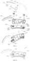
- the driver 3 includes a guide rail 32 and a guide assembly 33.
- the guide assembly 33 is connected to the deflector 9c.
- the guide rail 32 is engaged with the guide assembly 33 to define a movement trajectory of the guide assembly 33. Therefore, a shape of the guide rail 32 can determine a shape of the movement trajectory of the guide assembly 33, which in turn determines a shape of a movement trajectory of the deflector 9c. In this way, the deflector 9c can be driven to move along a determined movement trajectory to achieve desired opening and desired closing of the deflector.
- one driver 3 may be connected to two deflectors 9c to reduce a quantity of parts, thereby improving structural compactness of the air conditioner 1000.
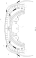
- two groups of guide rails 32 are provided and arranged symmetrically with respect to a reference surface (e.g., surface S illustrated in FIG. 5 ), and two groups of guide assemblies 33 are provided and also arranged symmetrically with respect to the reference surface, which facilitates symmetrical movements of the two deflectors 9c. Therefore, the two deflectors 9c are harmonious and consistent as a whole and more aesthetically favorable.
- the two deflectors 9c may also have a symmetrical shape with respect to the reference surface, in such a manner that the two deflectors 9c not only move in unison, but also exhibit symmetrical appearances.
- two air outlets 91a may also have symmetrical air outlet states.
- the driver 3 is only connected to one deflector 9c. In this case, only one guide rail 32 and one guide assembly 33 are required for the driver 3. In other embodiments, the driver 3 is connected to two deflectors 9c. The guide rail 32 and the guide assembly 33 may not be arranged symmetrically. In this way, personalized designs of the air conditioner 1000 can be increased.
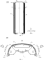
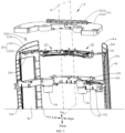
- the air outlet structure 100 of the present disclosure includes an air outlet frame 9a, the deflector 9c, and the driver 3. Two opposite surfaces of the air outlet frame 9a in a first direction are a front surface of the air outlet frame 9a and a rear surface of the air outlet frame 9a.
- the air outlet frame 9a has the air outlet 91a.
- the first direction is consistent with a thickness direction of the air outlet frame 9a.
- the deflector 9c is located at the front surface of the air outlet frame 9a and is movable between a closed position and an open position. That is, the deflector 9c is configured to cover the air outlet 91a when the deflector 9c is in the closed position and expose the air outlet 91a when the deflector 9c is in the open position.
- the deflector 9c located in the closed position and the deflector 9c located in the open position are arranged substantially in a second direction. The deflector 9c needs to move in the second direction during opening or closing of the deflector 9c.
- the second direction is perpendicular to the first direction, as illustrated in FIG. 3 .
- the deflector 9c can also be kept in other positions during use.
- the deflector 9c in a case where the air conditioner 1000 has a sleep mode, the deflector 9c further has a third position.
- the deflector 9c In the sleep mode of the air conditioner 1000, the deflector 9c is in the third position and blocks half of an area of the air outlet 91a, in such a manner that 50% of the area of the air outlet 91a can be used for circulating air while the other 50% of the area of the air outlet 91a cannot be used for circulating air, thereby reducing an area for direct blowing of the air outlet 91a and affecting an air output volume.
- two ends of the deflector 9c in the second direction are a deflector end A (the deflector end A is marked as 9-a in FIG. 5 ) and a deflector end B (the deflector end B is marked as 9-b in FIG. 5 ) 9-b.
- the deflector end B 9-b is located upstream of the deflector end A 9-a.
- the deflector end A 9-a is located upstream of the deflector end B 9-b.
- the second direction is a left-right direction.
- a right end of the deflector 9c is located upstream of a left end of the deflector 9c in an opening direction of the deflector 9c.
- the right end of the deflector 9c is the deflector end B 9-b of the deflector 9c
- the left end of the deflector 9c is the deflector end A 9-a of the deflector 9c.
- the left end of the deflector 9c is located upstream of the right end of the deflector 9c in the opening direction of the deflector 9c.
- the left end of the deflector 9c is the deflector end B 9-b of the deflector 9c
- the right end of the deflector 9c is the deflector end A 9-a of the deflector 9c.
- the second direction is a movement direction of the deflector 9c during the opening or the closing of the deflector 9c.
- the second direction may be a straight direction or a curve direction.
- the present disclosure is not limited in this regard.
- the second direction is consistent with a shape of the front surface of the air outlet frame 9a.
- the front surface of the air outlet frame 9a is a plane
- the second direction is the straight direction.
- the front surface of the air outlet frame 9a is a curved surface
- the second direction is the curve direction.
- the second direction is the straight direction when the front surface of the air outlet frame 9a is the curved surface.
- the present disclosure is not limited in this regard.
- the deflector 9c when the deflector 9c is in the closed position, at least part of the deflector 9c is located in the air outlet 91a to cover the air outlet 91a. That is, instead of simply blocking an outer side of the front surface of the air outlet frame 9a, the deflector 9c in the closed position at least partially extends into the air outlet 91a.
- the "outer side” in the present disclosure is a side facing towards an outside of the air conditioner 1000 in the first direction.
- an “inner side” in the present disclosure is a side facing towards a center of the air conditioner 1000 in the first direction.
- the at least part of the deflector 9c is located in the air outlet 91a when the deflector 9c is in the closed position, which can provide a number of advantages.
- a sealing of the air outlet 91a can be improved when the deflector 9c is in the closed position, and the sealing of the air outlet 91a is more conducive to improving the protection of an internal structure of the air conditioner 1000.
- the deflector 9c is stuck at the air outlet 91a, and thus the air outlet 91a has a constraining effect on the deflector 9c.
- the air outlet 91a provides partial support for the deflector 9c, avoiding overloading of the driver 3 caused by suspension of the deflector 9c.
- the deflector 9c since the at least part of the deflector 9c is inserted into the air outlet 91a when the deflector 9c is closed, the deflector 9c does not protrude too much from the front surface of the air outlet frame 9a. In this way, when the air conditioner 1000 is not in use, the deflector 9c and the front surface of the air outlet frame 9a form a seamless whole. Therefore, the air conditioner 1000 is harmonious as a whole.
- the guide rail 32 is constructed to guide, in response to the deflector 9c being opened, the deflector end B 9-b to move backwards and then move towards the open position. In this way, smooth opening and closing of the deflector 9c can be ensured.
- the guide rail 32 is constructed to guide, in response to the deflector 9c being opened, the deflector end B 9-b to move outwardly out of the air outlet 91a in the first direction and then move towards the open position in the second direction. It should be understood that since the deflector end B 9-b is located upstream of the deflector end A 9-a when the deflector 9c is opened, the deflector end B 9-b is equivalent to an arrowhead when the deflector 9c is assumed to be an arrow. Therefore, the guide rail 32 is constructed such that the deflector end B 9-b serving as the arrowhead moves out of the air outlet 91a in the first direction.
- the deflector 9c slightly interferes with an inner wall of the air outlet 91a when the deflector 9c moves towards the open position, which is favorable for the smooth opening and smooth closing of the deflector 9c.
- the deflector 9c may move in the second direction.
- the guide rail 32 is constructed to guide, in response to the deflector 9c approaching the closed position, the deflector end B 9-b to move into the air outlet 91a in the first direction.
- Such an arrangement of the guide rail 32 not only allows the deflector 9c to be smoothly opened or closed, but also allows the deflector 9c to move as closely as possible against the front surface of the air outlet frame 9a during the opening or the closing of the deflector 9c. In this way, when the air conditioner 1000 is in use, no large space needs to be vacated for the deflector 9c, which is conducive to reducing an overall area occupied by the air conditioner 1000 in use.
- At least two embodiments may be provided in terms of guiding, in response to the deflector 9c being opened, the deflector end B 9-b to move out of the air outlet 91a in the first direction and then move towards the open position in the second direction.
- the guide rail 32 is also constructed to guide, in response to the deflector 9c being opened, the deflector end A 9-a to move out of the air outlet 91a in the first direction and then move towards the open position in the second direction.
- the guide rail 32 is constructed to guide the entire deflector 9c to move out of the air outlet 91a in the first direction and then move towards the open position in the second direction.
- the guide rail 32 is constructed to guide, in response to the deflector 9c being opened, the deflector end A 9-a to move in the second direction until the deflector end A 9-a reaches the open position.
- the deflector 9c when the deflector 9c is in the closed position, only an inner side of the deflector 9c may be inserted into the air outlet frame 9a. For example, when the deflector 9c is in the closed position, two-thirds of a thickness of the deflector 9c is inserted into the air outlet frame 9a. In other specific embodiments, as illustrated in FIG. 3 , the deflector 9c may also be entirely inserted into the air outlet frame 9a when the deflector 9c is in the closed position. In this way, the deflector 9c in the closed position can be provided with different designs.
- an outer surface of the deflector 9c is flush with the front surface of the air outlet frame 9a. Therefore, a surface of the air outlet frame 9a remains substantially flat when the deflector 9c is closed.
- the deflector 9c extends in a third direction.
- the third direction is perpendicular to both the second direction and the first direction.
- the third direction is illustrated in FIG. 1 .
- the first direction and the second direction are illustrated in FIG. 3 .
- a projection of the outer surface of the deflector 9c on a plane perpendicular to the third direction is located in a projection of the air outlet frame 9a on a plane perpendicular to the third direction, which ensures that the outer surface of the deflector 9c is completely prevented from protruding beyond the front surface of the air outlet frame 9a, providing a more effective hiding effect of the deflector 9c when the deflector 9c is closed.
- the guide assembly 33 includes a first pressure plate 331 connected to the deflector 9c.
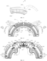
- the guide rail 32 has a first guide groove 321 and a second guide groove 322.
- the first guide groove 321 extends in the second direction and has a first guide end A (the first guide end A is marked as 21-a in FIG. 12 ) and a first guide end B (the first guide end B is marked as 21-b in FIG. 12 ).
- the second guide groove 322 has a second guide end A (the second guide end A is marked as 22-a in FIG. 12 ) and a second guide end B (the second guide end B is marked as 22-b in FIG. 12 ).
- the first pressure plate 331 is provided with a first guide post 3311 and a second guide post 3312.
- the first guide post 3311 is engaged in the first guide groove 321.
- the second guide post 3312 is engaged in the second guide groove 322.
- the first guide post 3311 slides from the first guide end A 21-a to the first guide end B 21-b in the first guide groove 321, and the second guide post 3312 slides from the second guide end A 22-a to the second guide end B 22-b in the second guide groove 322.
- the first direction is consistent with a width direction of the first guide groove 321.
- the second direction is consistent with a length direction of the first guide groove 321.
- the third direction is consistent with a depth direction of the first guide groove 321.
- two sides of the first guide groove 321 are an outer side and an inner side, respectively.
- the second guide groove 322 includes a protrusion segment 3221 and a sliding segment 3222.
- An end of the protrusion segment 3221 is the second guide end A 22-a.
- the protrusion segment 3221 gradually extends in the second direction from the second guide end A 22-a while extending outwardly in the first direction.
- the sliding segment 3222 extends away from the first guide groove 321 from another end of the protrusion segment 3221 in the second direction.
- the deflector end A 9-a moves in line with the first guide post 3311, while the deflector end B 9-b moves in line with the second guide post 3312. In this way, when the deflector 9c moves from the closed position to the open position, the deflector end A 9-a moves substantially in the second direction. When the deflector 9c moves from the closed position to the open position, the entire deflector end B 9-b also moves in the second direction. However, at a beginning of a movement of the deflector end B 9-b, the deflector end B 9-b moves outwardly in the first direction, in such a manner that the deflector end B 9-b can move out of the air outlet 91a.
- the deflector end A 9-b moves substantially in the second direction.
- the entire deflector end B 9-b also moves in the second direction.
- the deflector end B 9-b moves inwardly in the first direction, in such a manner that the deflector end B 9-b can move into the air outlet 91a.
- the first guide groove 321 and the second guide groove 322, along with the first guide post 3311 of the first pressure plate 331 and the second guide post 3312 of the first pressure plate 331, allow the entire movement trajectory of the deflector 9c to be set in the second direction.
- the deflector 9c is slightly deflected at a beginning of the opening of the deflector 9c and at an end of the closing of the deflector 9c, in such a manner that the deflector end B 9-b can move into and out of the air outlet 91a.
- the entire deflector 9c can move along the front surface of the air outlet frame 9a after moving out of the air outlet 91a during the opening of the deflector 9c and before moving into the air outlet 91a during the closing of the deflector 9c, which is conducive to reducing a space occupied by the deflector 9c during the opening or the closing of the deflector 9c.
- the above structures make the movement trajectory of the deflector 9c clear and simple. Therefore, the deflector 9c is less likely to get stuck.
- the second guide end A 22-a is connected to the first guide end B 21-b.
- a spacer 3202 is disposed between the second guide end A 22-a and the first guide end B 21-b.
- the first guide groove 321 and the second guide groove 322 can be designed as a single groove, and then separated into two guide grooves by the spacer 3202.
- the two guide grooves share the spacer 3202 as an abutment end at an end of each of the two guide grooves, which simplifies a structure and facilitates the manufacturing.
- the first guide post 3311 in the open position, is located at the first guide end A 21-a and the second guide post 3312 is located at the second guide end A 22-a.
- the first guide post 3311 In the closed position, the first guide post 3311 is located at the first guide end B 21-b and the second guide post 3312 is located at the second guide end B 22-b.
- the end of the first guide groove 321 and the end of the second guide groove 322 are used for limiting positions of the first guide post 3311 and the second guide post 3312 when the deflector 9c is in the open position or the closed position. Therefore, two extreme positions of the deflector 9c can be limited by the ends of the two guide grooves to prevent the deflector 9c from wobbling in the open position or the closed position.
- the protrusion segment 3221 has a dimension in the first direction greater than or equal to a dimension of the air outlet 91a in the first direction.
- the first direction is the thickness direction of the air outlet frame 9a and a thickness direction of the air outlet 91a.
- an extent of movement of the deflector end B 9-b is substantially equal to or greater than a thickness of the air outlet 91a, enabling the deflector end B 9-b to be completely separated from the air outlet 91 and the deflector end B 9-b to move to the outer side of the air outlet frame 9a. Therefore, obstructions are reduced for subsequent movements.
- the protrusion segment 3221 has the dimension in the first direction smaller than the thickness of the air outlet 91a. Therefore, when the deflector 9c is in the closed position, a part of the deflector 9c inserted into the air outlet 91a is limited.
- the second guide groove 322 further includes a retraction segment 3223.
- the retraction segment 3223 extends inwardly in the first direction while extending from another end of the sliding segment 3222 in the second direction. That is, the retraction segment 3223 and the protrusion segment 3221 are located at a same side of two ends of the sliding segment 3222.
- the retraction segment 3223 gradually extends from the other end of the sliding segment 3222 away from the rear surface of the air outlet frame 9a.
- the second guide end B 22-b is located at an end of the retraction segment 3223 away from the sliding segment 3222.
- the deflector 9c when the deflector 9c is opened and close to the open position, the deflector end B 9-b gradually approaches the front surface of the air outlet frame 9a. Therefore, the deflector 9c occupies a small space in the open position. In addition, a large gap can be hardly created between the deflector 9c and the front surface of the air outlet frame 9a.
- the air outlet frame 9a provides protection for the deflector 9c.
- the guide rail 32 further has a third guide groove 323 and a fourth guide groove 324 that both extend in the second direction.
- the guide assembly 33 further includes a second pressure plate 332.
- the first pressure plate 331 is movably connected to the second pressure plate 332.
- the second pressure plate 332 is provided with a third guide post 3321 and a fourth guide post 3322.
- the third guide post 3321 is engaged in the third guide groove 323.
- the fourth guide post 3322 is engaged in the fourth guide groove 324.
- the second pressure plate 332 can be moved to drive the first pressure plate 331 to move. Therefore, the deflector 9c is driven to move.
- An engagement between the second pressure plate 332 and the guide rail 32 enables the second pressure plate 332 to move smoothly.
- the driver 3 includes a drive member 34 connected to the second pressure plate 332.
- the drive member 34 is configured to drive the second pressure plate 332 to move.
- various forms of movement are available for the drive member 34 to drive the second pressure plate 332.
- the second pressure plate 332 can be driven translationally or rotationally.
- the drive member 34 may be a conventional motor, a linear motor, a piston, a cylinder, or the like.
- the drive member 34 can be configured to directly drive the second pressure plate 332 to move, or drive the second pressure plate 332 to move through a transmission structure.
- the drive member 34 is a stepper motor, which is controllable.
- the second pressure plate 332 is further provided with a rack 352.
- the drive member 34 is a motor.
- the motor is engaged with the rack 352 through a gear 351.
- the rack 352 can realize that the second pressure plate 332, while moving, is guided by the guide rail 32 to undergo a small degree of rotation.
- a movement trajectory of the second pressure plate 332 has a small curvature, in such a manner that when the second pressure plate 332 drives the first pressure plate 331 to move, the first pressure plate 331 can have a small curvature relative to the movement trajectory of the second pressure plate 332.
- the first pressure plate 331 can have a relatively large degree of rotation when moving relative to the air outlet 91a, enabling the deflector 9c to effectively avoid obstacles during the opening or the closing of the deflector 9c.
- the "large degree of rotation” and the “small degree of rotation” are relative terms.
- the deflector 9c needs to be deflected by five degrees at the beginning of the opening of the deflector 9c.
- the second pressure plate 332 can be substantially deflected by two degrees relative to the air outlet 91a and substantially deflected by three degrees relative to the first pressure plate 331 at the beginning of the opening of the deflector 9c. After a deflection amount is apportioned in this way, each pressure plate undergoes a relatively small degree of rotation, which is conducive to improving movement precision of the overall movement, reducing a chance of getting stuck.
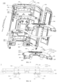
- the driver 3 includes a cover body assembly 31 and the guide assembly 33.
- a cover body assembly 31 defines a movable cavity 313.
- the cover body assembly 31 is provided with the guide rail 32.
- the guide assembly 33 includes the first pressure plate 331 and the second pressure plate 332.
- the first pressure plate 331 and the second pressure plate 332 are disposed in the movable cavity 313.
- the first pressure plate 331 is connected to the deflector 9c.
- the second pressure plate 332 is stacked on the first pressure plate 331.
- the second pressure plate 332 drives the first pressure plate 331 to move when moving.
- the first pressure plate 331 and the second pressure plate 332 are stacked on each other in the third direction.
- the first direction is a thickness direction of the deflector 9c and the width direction of the first guide groove 321.
- the second direction is consistent with the length direction of the first guide groove 321 and is generally perpendicular to the first direction.
- the third direction is consistent with the depth direction of the first guide groove 321 and is usually perpendicular to the first direction and the second direction.
- the driver 3 as a whole is flat in the third direction. When the deflector 9c extends in the third direction, the driver 3 may be mounted at an end of the deflector 9c. Therefore, the driver 3 as a whole occupies a small space, which allows the driver 3 to avoid an air outlet path and give way to an air outlet duct.
- the second pressure plate 332 is connected to the first pressure plate 331 by a rotary shaft 3301.
- the guide rail 32 is engaged with the first pressure plate 331 and the second pressure plate 332 to define the movement trajectory.
- the first pressure plate 331 and the second pressure plate 332 have different movement trajectories. After such an arrangement, the first pressure plate 331 is driven to move when the second pressure plate 332 moves. The movements of both the first pressure plate 331 and the second pressure plate 332 are constrained by guiding of the guide rail 32.
- first pressure plate 331 and the second pressure plate 332 are connected by the rotary shaft 3301 after being stacked on each other, the first pressure plate 331 and the second pressure plate 332 are constrained to each other. Therefore, the first pressure plate 331 and the second pressure plate 332 can move smoothly, reducing occurrences of dead points and jams.
- the first pressure plate 331 Since the first pressure plate 331 is connected to the second pressure plate 332 by the rotary shaft 3301, the first pressure plate 331 can be deflected relative to the second pressure plate 332 while the second pressure plate 332 drives the first pressure plate 331 to move. Therefore, the overall movement trajectory of the deflector 9c during the opening or the closing of the deflector 9c is substantially the same as the movement trajectory of the second pressure plate 332. Part of the deflector 9c during the opening or the closing of the deflector 9c can be deflected with a deflection of the first pressure plate 331, which is conducive to setting a deflection form of the deflector 9c as desired.
- the first pressure plate 331 may be deflected relative to the second pressure plate 332.
- a deflection time point is determined as an end time point of the closing of the deflector 9c
- the deflector 9c may be deflected while moving. In this way, the deflector 9c can be more tightly engaged with a surface of the air conditioner, which results in a relatively small gap between the surface of the air conditioner and the deflector 9c. Therefore, the deflector 9c is prevented from protruding too much from the surface of the air conditioner.
- the deflector 9c may be inserted into the air outlet 91a to ensure tightness of the air outlet 91a.
- the second pressure plate 332 is provided with the rotary shaft 3301.
- the first pressure plate 331 has a shaft hole 3302 engaged with the rotary shaft 3301, which facilitates an assembly.
- an engagement between the rotary shaft 3301 and the shaft hole 3302 can also provide a position limitation.
- the rotary shaft 3301 and the second pressure plate 332 are integrally formed to enhance structural strength and stiffness of the rotary shaft 3301, reducing a possibility of fractures.
- the solutions of the present disclosure can also be achieved in other ways.
- the rotary shaft 3301 may be a separate part.
- Each of the first pressure plate 331 and the second pressure plate 332 has the shaft hole 3302. The rotary shaft 3301 is inserted into and fixed in the two shaft holes 3302.
- the driver 3 further includes a shaft sleeve 39 sleeved around the rotary shaft 3301, which can reduce wear caused during a rotation of the rotary shaft 3301, prolonging a service life of the driver 3.
- the rotary shaft 3301 has a stopper screw hole 3305.
- the shaft sleeve 39 is defined at the rotary shaft 3301 by connecting a stopper screw to the stopper screw hole 3305.
- the guide assembly 33 further includes a support plate 333 sandwiched between the first pressure plate 331 and the second pressure plate 332.
- the support plate 333 is fixedly connected to the first pressure plate 331.
- the connection portion 334 and the support plate 333 are integrally formed.
- the support plate 333 is configured to support the deflector 9c.
- Each of the first pressure plate 331 and the second pressure plate 332 is engaged with the guide rail 32 to define the movement trajectory of the deflector 9c.
- the parts are separately processed to conveniently meet their respective needs.
- the first pressure plate 331 and the second pressure plate 332 need to be processed into shapes that facilitate guiding.
- the support plate 333 needs to be processed into a shape that facilitates a connection to the deflector 9c.
- the first pressure plate 331 is provided with limit ribs 3313 engaged with two opposite sides of the support plate 333 to improve an assembly efficiency between the first pressure plate 331 and the support plate 333.
- the first pressure plate 331 is provided with limit ribs 3313 at two sides of the first pressure plate 331 in the first direction, in such a manner that the support plate 333 is constrained at two sides of the support plate 333 in the first direction.
- a stable engagement is formed between the first pressure plate 331 and the support plate 333 through a fastening connection.
- the first pressure plate 331 has a first screw hole 3315
- the support plate 333 has a second screw hole 3331.
- the first screw hole 3315 and the second screw hole 3331 are opposite to each other and connected by a screw.
- the first pressure plate 331 and the support plate 333 are fixed through welding after being positioned.
- first pressure plate 331 has a first auxiliary positioning hole 3316
- the support plate 333 has a second auxiliary positioning hole 3332.
- An auxiliary positioning pin 3333 is inserted into the first auxiliary positioning hole 3316 and the second auxiliary positioning hole 3332 to realize positioning.
- the support plate 333 and the first pressure plate 331 may be integrally formed.
- the support plate 333 is disposed in the cover body assembly 31.
- the cover body assembly 31 has a passage opening 314. Part of the support plate 333 extends out of the passage opening 314 to be connected to the deflector 9c.
- one of the first pressure plate 331 and the second pressure plate 332 is provided with a sliding post 3303, and another one of the first pressure plate 331 and the second pressure plate 332 has a sliding groove 3304.
- the sliding groove 3304 is in a circular arc shape centered on a center of the rotary shaft 3301.
- the sliding post 3303 is engaged in the sliding groove 3304.
- the second pressure plate 332 is provided with the sliding post 3303.
- the first pressure plate 331 has the sliding groove 3304.
- the sliding groove 3304 is in a circular arc shape.
- the sliding groove 3304 and the shaft hole 3302 are located at two ends of the second pressure plate 332 in the second direction.
- the sliding groove 3304 is located at a leftmost end of the second pressure plate 332, while the shaft hole 3302 is located at a rightmost end of the second pressure plate 332. In this way, a dimension of the first pressure plate 331 in the second direction is fully used to allow the first pressure plate 331 to conveniently rotate relative to the second pressure plate 332.
- the driver 3 further includes the shaft sleeve 39 sleeved around the sliding post 3303. Therefore, the wear of the sliding post 3303 can be reduced, which is conducive to prolonging the service life of the driver 3.
- the sliding post 3303 has the stopper screw hole 3305.
- the shaft sleeve 39 is defined at the sliding post 3303 through connecting a stopper screw to the stopper screw hole 3305.
- the first guide groove 321, the second guide groove 322, the third guide groove 323, and the fourth guide groove 324 are formed at a side of the first pressure plate 331 in the third direction.
- the first guide groove 321, the second guide groove 322, the third guide groove 323, and the fourth guide groove 324 are formed at two sides of the first pressure plate 321 in the third direction.
- the third direction is an up-down direction.
- the guide rail 32 may be disposed only above the first pressure plate 331 or only below the second pressure plate 332.
- the guide rails 32 may be arranged corresponding to each other in the up-down direction. That is, the guide rails 32 are arranged above the first pressure plate 331 and below the second pressure plate 332.
- the first pressure plate 331 may be engaged only with the guide rail 32 arranged above the first pressure plate 331. Also, the first pressure plate 331 may be engaged with the guide rails 32 arranged above the first pressure plate 331 and below the second pressure plate 332 simultaneously.
- the second pressure plate 332 may be engaged only with the guide rail 32 arranged below the second pressure plate 332. Also, the second pressure plate 332 may be engaged with the guide rails 32 arranged above the first pressure plate 331 and below the second pressure plate 332 simultaneously. The present disclosure is not limited in this regard.
- a guide plate 3201 is disposed at an inner surface of the cover body assembly 31.
- the guide rail 32 is defined by the guide plate 3201. Therefore, a simple and compact structure is realized.
- the guide plate 3201 and the cover body assembly 31 are integrally formed, which provides high reliability and achieves a long service life.
- the guide assembly 33 has a connection portion 334 connected to the deflector 9c.
- the connection portion 334 may be connected to the first pressure plate 331. The connection portion 334 is driven to move through the movement of the first pressure plate 331, and thus the deflector 9c is driven to move.
- the guide assembly 33 includes the support plate 333 sandwiched between the first pressure plate 331 and the second pressure plate 332.
- the connection portion 334 is connected to the support plate 333. In this way, a relatively small interference is generated when the first pressure plate 331 is assembled with the guide rail 32.
- the connection portion 334 and the support plate 333 are integrally formed, which can improve overall structural stiffness, reducing a risk of fracture. Further, the connection portion 334 and the support plate 333 are integrally formed as a sheet metal part.
- connection portion 334 is connected to the deflector 9c by a positioning structure 325 and a fastener 3255. Therefore, the connection portion 334 and the deflector 9c are conveniently mounted and positioned.
- the connection portion 334 has at least two positioning holes 3251.
- the deflector 9c is provided with positioning posts 3252 inserted into the at least two positioning holes 3251 in a one-to-one correspondence.
- the connection portion 334 has a first connection hole 3253.
- the deflector 9c has a second connection hole 3254 corresponding to the first connection hole 3253.
- the first connection hole 3253 is connected to the second connection hole 3254 by the fastener 3255 such as a screw and a rivet.
- one of the first connection hole 3253 and the second connection hole 3254 is a threaded hole, which can reduce time for screwing a nut.
- the positioning hole 3251 penetrates the connection portion 334 in the third direction.
- the positioning post 3252 is inserted into or pulled out of the positioning hole 3251 in the third direction.
- the fastener 3255 is connected to the first connection hole 3253 and the second connection hole 3254 in the third direction. Therefore, a consistent assembly direction is ensured, which facilitates mounting.
- the deflector 9c when the deflector 9c is an arc-shaped plate, the first guide groove 321, the sliding segment 3222, the third guide groove 323, and the fourth guide groove 324 are arc-shaped grooves concentrically arranged with each other and concentrically arranged with the deflector 9c. In this way, the entire deflector 9c can travel along an arc-shaped movement trajectory during the opening and the closing of the deflector 9c, improving consistency of a guide direction and smoothness of the movement of the guide assembly 33.
- one drive member 34 when the driver 3 can drive two deflectors 9c to move, one drive member 34 may be provided.
- the one drive member 34 is connected to two guide assemblies 33 through the transmission structure, which realizes a one-driving-two structure, reducing a quantity of the drive members 34.
- two drive members 34 may be provided.
- the two drive members 34 are connected to the two guide assemblies 33, respectively, to reduce a quantity of parts of the transmission structure, reducing a volume of the transmission structure.
- the two drive members 34 can be controlled separately, in such a manner that the two deflectors 9c can move synchronously or the two deflector 9c can move out of sync or move differently, adapting to more demands for the air outlet.
- the cover body assembly 31 includes a first cover body 311 and a second cover body 312 that are assembled with each other to define the movable cavity 313.
- the guide rails 32 of a same shape are arranged on the first cover body 311 and the second cover body 312.
- the first cover body 311 and the second cover body 312 are assembled with each other to define the cover body assembly 31, which is convenient for mounting the guide assembly 33 in the cover body assembly 31.
- the first cover body 311 and the second cover body 312 are flat cover bodies.
- the first cover body 311 and the second cover body 312 are assembled with each other in the third direction.
- Arranging the guide rails 32 of the same shape on the first cover body 311 and the second cover body 312 facilitates an engagement between the guide assembly 33 and each of the first cover body 31 and the second cover body 312, which constrains the movement trajectory of the guide assembly 33. In this way, stability of the movement of the guide assembly 33 can be facilitated. In addition, support can be provided for the guide assembly 33 when the guide assembly 33 is engaged with the guide rail 32 at the first cover body 311 and the guide rail 32 at the second cover body 312.
- a plurality of engagement members are provided between the first cover body 311 and the second cover body 312.
- the first cover body 311 and the second cover body 312 are connected by a screw, so that the first cover body 311 and the second cover body 312 are stably and reliably engaged.
- the driver 3 is mounted at the air outlet frame 9a, in such a manner that a stable connection can be formed between the driver 3 and the deflector 9c to ensure a reliable movement.
- the air outlet frame 9a has two air outlets 91a arranged in the second direction. Each air outlet 91a corresponds to one deflector 9c.
- the cover body assembly 31 is provided with two groups of guide rails 32 that are arranged symmetrically.
- the driver 3 includes two groups of guide assemblies 33 being engaged with the two groups of guide rails 32, respectively. Each group of guide assemblies 33 is connected to one deflector 9c. In this way, the two deflectors 9c can move symmetrically, and thus consistent movements and satisfactory coordination are achieved.
- the air outlet structure 100 includes the air outlet frame 9a, the deflector 9c, and the driver 3.
- the two opposite surfaces of the air outlet frame 9a in the first direction are the front surface of the air outlet frame 9a and the rear surface of the air outlet frame 9a.
- the air outlet frame 9a has the air outlet 91a.
- the deflector 9c is located at the front surface of the air outlet frame 9a and is movable between the closed position and the open position in the second direction. When the deflector 9c is in the closed position, the at least part of the deflector 9c is located in the air outlet 91a to cover the air outlet 91a.
- the two ends of the deflector 9c in the second direction are the deflector end A 9-a and the deflector end B 9-b.
- the driver 3 is mounted at the air outlet frame 9a and is connected to the deflector 9c to drive the deflector 9c to move.
- the driver 3 includes the guide rail 32 and the guide assembly 33.
- the guide assembly 33 is connected to the deflector 9c.
- the guide rail 32 is engaged with the guide assembly 33 to define the movement trajectory of the guide assembly 33.
- the guide rail 32 is constructed to guide, in response to the deflector 9c being opened, the deflector end B 9-b to move out of the air outlet 91a in the first direction and then move towards the open position in the second direction.
- the air conditioner 1000 includes the above-mentioned air outlet structure 100.
- the two opposite surfaces of the air outlet frame 9a in the first direction are the front surface of the air outlet frame 9a and the rear surface of the air outlet frame 9a.
- the air outlet frame 9a has the two air outlets 91a arranged in the second direction.
- Two deflectors 9c are provided and located at the front surface of the air outlet frame 9a.
- the two deflectors 9c are arranged corresponding to the two air outlets 91a in a one-to-one correspondence.
- the deflector 9c is movable between the closed position and the open position in the second direction.
- the driver 3 is mounted at the air outlet frame 9a and is connected to the deflector 9c to drive the deflector 9c to move.
- the driver 3 is the driver 3 according to the above-mentioned embodiments.
- the deflector 9c is disposed at the front surface of the air outlet frame 9a.
- the driver 3 is disposed at the rear surface of the air outlet frame 9a. In this way, the driver 3 is close to the deflector 9c, which is conducive to driving the deflector 9c to move.
- the air outlet frame 9a has a relatively firm structure, fixedly mounting the driver 3 to the air outlet frame 9a can ensure stability.
- the air outlet frame 9a has a mounting opening 95a.
- the driver 3 extends to the front surface of the air outlet frame 9a through the mounting opening 95a and is connected to the deflector 9c.
- the rear surface of the air outlet frame 9a has a first fixation hole 361 and a second fixation hole 362.
- the driver 3 includes the cover body assembly 31.
- the cover body assembly 31 includes the first cover body 311 and the second cover body 312 that are assembled with each other.
- the first cover body 311 has a first mounting hole 364 opposite to the first fixation hole 361.
- the second cover body 312 has a second mounting hole 365 opposite to the second fixation hole 362. After being aligned with each other, holes are connected to each other by a fastener, which can improve reliability of an overall connection.
- the reliable cover body assembly 31 is formed through keeping the first cover body 311 and the second cover body 312 connected, which avoids an assembly failure of the guide assembly 33 due to a formation of a gap between the first cover body 311 and the second cover body 312.
- the cover body assembly 31 is inserted into the air outlet frame 9a towards the rear surface of the air outlet frame 9a, in such a manner that the first mounting hole 364 of the first cover body 311 is aligned with the first fixation hole 361 at the rear surface of the air outlet frame 9a, and the second mounting hole 365 of the second cover body 312 is aligned with the second fixation hole 362.
- a limit structure is further provided between the air outlet frame 9a and the driver 3. Assembly strength between the driver 3 and the air outlet frame 9a can be further enhanced by the limit structure to ensure movement reliability of movement parts in the driver 3.
- one or a plurality of first fixation holes 361 and one or a plurality of second fixation holes 362 may be formed at the rear surface of the air outlet frame 9a.
- a quantity of the first mounting holes 364 corresponds to that of the second mounting holes 365.
- all of the first fixation hole 361, the second fixation hole 362, the first mounting hole 364, and the second mounting hole 365 may be threaded holes, which are fastened by screws after hole structures are aligned. Therefore, the first cover body 311 and the second cover body 312 are multi-directionally and firmly connected to the rear surface of the air outlet frame 9a.
- the quantity and a distribution manner of the first mounting holes 364 formed at the first cover body 311 are not specifically limited.
- the quantity and a distribution manner of the second mounting holes 365 formed at the second cover body 312 are not specifically limited.
- the first fixation holes 361 and the second fixation holes 362 are arranged corresponding to each other.
- two first mounting holes 364 may be symmetrically arranged at the first cover body 311.
- two second mounting holes 365 may be symmetrically arranged at the second cover body 312.
- a spacing of the two first mounting holes 364 at the first cover body 311 is smaller than a spacing of the two second mounting holes 365 at the second cover body 312, to allow a connection of the first cover body 311 to be more focused on positioning during mounting and a connection of the second cover body 312 to be more focused on load-bearing and stability during mounting.
- the quantity of the second mounting holes 365 formed at the second cover body 312 may be greater than the quantity of the first mounting holes 364 formed at the first cover body 311 to provide better support for the second cover body 312, further improving mounting stability.
- the first cover body 311 includes an upper cover body 3111 and a positioning baffle 3112.
- the positioning baffle 3112 extends upwardly from a top of the upper cover body 3111.
- the first mounting hole 364 is formed at the positioning baffle 3112.
- the positioning baffle 3112 can provide positioning and guidance for the first cover body 311. After the first cover body 311 is positioned and mounted, the positioning baffle 3112 abuts with the rear surface of the air outlet frame 9a to limit a forward movement of the first cover body 311, which allows the first mounting hole 364 to be aligned with the first fixation hole 361.
- the limit structure includes a first limit group formed between the air outlet frame 9a and the positioning baffle 3112. With the first limit group, firmness obtained after the mounting can be further improved.
- the positioning baffle 3112 and the first cover body 311 may be integrally formed, or the positioning baffle 3112 may be a removable structure fixed at the first cover body 311 by a connector.
- the second mounting hole 365 may be formed at a left end and a right end of the second cover body 312 to provide fixation for two sides of the second cover body 312.
- the second cover body 312 has high overall stability, providing support for the upper cover body 3111.
- the first limit group includes a first limit hole 366 and a first limit pin 367.
- the first limit hole 366 is located at the positioning baffle 3112 and close to the first mounting hole 364.
- the first limit pin 367 is disposed at the air outlet frame 9a.
- the first limit pin 367 is inserted into the first limit hole 366 to limit a leftward movement or a rightward movement of the upper cover body 3111, which provides positioning during the mounting, and limits movements in all directions after the mounting. In this way, the mounting is facilitated while the assembly strength obtained after the mounting is enhanced, reducing occurrences of loosening of the driver 3 in the left-right direction.
- an upper boss 92 is formed at the rear surface of the air outlet frame 9a.
- the upper cover body 3111 is located below the upper boss 92.
- the positioning baffle 3112 abuts with a rear side of the upper boss 92.
- the first fixation hole 361 is located at the upper boss 92.
- the first limit group is located between the upper boss 92 and the positioning baffle 3112.
- the upper boss 92 is engaged with the positioning baffle 3112 to provide guidance for the mounting of the driver 3, achieving accurate mounting and accurate positioning.
- positions of the upper boss 92 and the positioning baffle 3112 are mutually limited by each other, enhancing mounting strength.
- a length of the upper boss 92 in a horizontal direction may be set to be the same as a distance between the positioning baffle 3112 and a front end face of the upper cover body 3111, in such a manner that when the positioning baffle 3112 abuts with the rear side of the upper boss 92, the front end face of the upper cover body 3111 abuts with the rear surface of the air outlet frame 9a to realize a compact connection. Structures abutting with each other can further improve a degree of stability obtained after the mounting.
- the limit structure includes a second limit group formed between the first cover body 311 and the air outlet frame 9a and a third limit group formed between the second cover body 312 and the air outlet frame 9a.
- the second limit group and the third limit group each of the first cover body 311, the second cover body 312, and the rear surface of the air outlet frame 9a has a structure for positioning and connection. Therefore, the driver 3 rarely wobbles after the mounting, enhancing mounting firmness and the assembly strength.
- the second limit group includes a second limit hole 368 and a second limit pin 369.
- the second limit pin 369 is formed at a front side of the first cover body 311.
- the third limit group includes a third limit hole 371 and a third limit pin 372.
- the third limit pin 372 is formed at a front side of the second cover body 312.
- the second limit hole 368 and the third limit hole 371 are formed at the air outlet frame 9a.
- the first cover body 311 and the second cover body 312 are positioned and mounted to the rear surface of the air outlet frame 9a through pin-hole structures of both the second limit group and the third limit group, respectively.
- the pin-hole structures can guide the driver 3 to move towards the rear surface of the air outlet frame 9a and prevent the driver 3 from wobbling in all directions.
- the second limit pin 369 and the third limit pin 372 may be cross-shaped pins.
- the second limit hole 368 and third limit hole 371 are cross-shaped pinholes. An engagement between the cross-shaped pins and the cross-shaped pinholes enables the driver 3 to be less likely to wobble after the pins and the pinholes are connected, achieving a more satisfactory positioning effect.
- a lower boss 93 is formed at the rear surface of the air outlet frame 9a.
- the second cover body 312 is located above the lower boss 93.
- a lower surface of the second cover body 312 moves along an upper surface of the lower boss 93 towards the rear surface of the air outlet frame 9a.
- the lower boss 93 provides support for the second cover body 312 and guides mounting of the second cover body 312, improving a positioning accuracy during the mounting and making the mounting more convenient.
- the lower boss 93 and the air outlet frame 9a may be integrally formed, or the lower boss 93 may be a removable structure connected to the rear surface of the air outlet frame 9a by the connector.
- a left side and a right side of the air outlet frame 9a extend rearwards to form an arc shape.
- a front surface of the driver 3 is formed as an arc surface mated with the air outlet frame 9a.
- a left end and a right end of the air outlet frame 9a are provided with a stud 901 extending rearwards.
- the stud 901 has the second fixation hole 362.
- a left end and a right end of the second cover body 312 are formed as a connection lug 363.
- the connection lug 363 has the second mounting hole 365.
- a connection is realized by the connection lug 363 through aligning the second mounting hole 365 with the second fixation hole 362.
- the connection lug 363 formed at the second cover body 312 the second cover body 312 is further reinforced at the rear surface of the air outlet frame 9a, further reinforcing a left side and a right side of the switch-actuated door drive assembly 20 to enhance overall assembly strength.
- the air outlet frame 9a has the air outlet 91a at each of the left side and the right side of the air outlet frame 9a.
- the air outlet 91a is located in an arc-shaped region at each of two sides of the air outlet frame 9a.
- the air conditioner 1000 further includes two deflectors 9c.
- the two deflectors 9c are slidable towards two sides to expose the two air outlets 91a. When the two deflectors 9c slide towards a middle of the air outlet frame 9a, the two air outlets 91a can be covered.
- the driver 3 is configured to drive the deflector 9c to move.
- the driver 3 drives the deflector 9c to move towards the two sides and backwards to expose the air outlet 91a.
- the driver 3 drives the deflector 9c to move towards a middle of the front surface to cover the air outlet 91a, preventing dust from entering the air outlet 91a.
- one deflector 9c is connected to two drivers 3.
- the two drivers 3 are spaced apart in the third direction, enabling the deflector 9c to move effectively at two ends in the third direction.
- the third direction is the up-down direction.
- the deflector 9c has an upper end connected to one driver 3 and a lower end connected to another driver 3. Simultaneous driving of the upper and lower ends of the deflector 9c effectively facilitates driving of the deflector 9c, in such a manner that the upper end and the lower end of the deflector 9c are driven simultaneously. Therefore, the deflector 9c can be from being distorted by asynchronous driving of the upper and lower ends of the deflector 9c, improving stability of an operation of the deflector 9c.
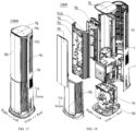
- the air conditioner 1000 is a vertical air conditioner including a fresh air component 9e and an indoor heat exchange component 9f.
- the indoor heat exchange component 9f is located above the fresh air component 9e.
- the fresh air component 9e realizes a fresh air function for indoor air.
- An indoor fresh air volume is increased by introducing outdoor air into an indoor environment.
- the indoor heat exchange component 9f is configured to heat or cool the indoor air and adjust a temperature of the indoor air.
- the vertical air conditioner further includes a chassis 9d, the air outlet frame 9a, a front panel 9b, a lower panel 9b, an outer housing panel 9i, and a top cover 9j, which substantially form a case of the vertical air conditioner.
- the chassis 9d is located at a bottom of the vertical air conditioner.
- the lower panel 9b is connected to and located above the chassis 9d and is located at a front side.
- the air outlet frame 9a is connected to and located above the lower panel 9b.
- the outer housing panel 9i is connected to and located above the chassis 9d and is located at a rear side.
- the top cover 9j is located directly above the chassis 9d. Two sides of each of the air outlet frame 9a and the lower panel 9b extend rearwards.
- Two sides of the outer housing panel 9i extend forwards and are connected to the two sides of the outer housing panel 9i.
- the two sides of the outer housing panel 9i are connected to the two sides of the lower panel 9b.
- the top cover 9j is connected to the air outlet frame 9a and a top of the outer housing panel 9i.
- a mounting cavity is formed by the air outlet frame 9a, the lower panel 9b, the outer housing panel 9i, the top cover 9j, and the chassis 9d.
- the fresh air component 9e and the indoor heat exchange component 9f are mounted in the mounting cavity.
- the vertical air conditioner further includes the front panel 9b mounted at the front side of the air outlet frame 9a, to decorate and cover an internal structure of the air outlet frame 9a.
- the air outlet frame 9a has the air outlet 91a at each of the left side and the right side of the front panel 9b.
- the vertical air conditioner further includes two deflectors 9c.
- the two deflectors 9c are slidable towards two sides to expose the air outlet 91a.
- the outer housing panel 9i has the air inlet 91i. The indoor air, after being drawn into the mounting cavity rearwardly, can be blown from the air outlet 91a at the front side into the indoor environment.
- the vertical air conditioner further includes an air duct component 9g disposed in the mounting cavity.
- the air duct component 9g is arranged corresponding to the indoor heat exchange component 9f.
- the air duct component 9g is configured to drive the airflow to flow through the indoor heat exchange component 9f for heat exchange, and then direct the airflow towards the indoor environment.
- the air duct component 9g includes a drive fan and an air duct member.
- the drive fan is mounted at the air duct member.
- the air duct component 9g is mounted at a front side of the indoor heat exchange component 9f.
- the air duct component 9g is wrapped between the indoor heat exchange component 9f and the air outlet frame 9a.
Landscapes
- Engineering & Computer Science (AREA)
- Chemical & Material Sciences (AREA)
- Combustion & Propulsion (AREA)
- Mechanical Engineering (AREA)
- General Engineering & Computer Science (AREA)
- Air-Flow Control Members (AREA)
Abstract
Description
- This application is based on and claims priorities to
Chinese patent application No. 202123214751.8, filed on December 17, 2021 Chinese patent application No. 202123203830.9, filed on December 17, 2021 - The present disclosure relates to the field of air conditioning devices, and more particularly, to an air outlet structure of an air conditioner and an air conditioner.
- To make an air conditioner aesthetically favorable and dustproof, a louver panel or a shield panel is generally disposed at an air outlet of the air conditioner. The louver panel or the shield panel is opened or closed through a switch-actuated door drive mechanism.
- When the switch-actuated door is the shield panel, the shield panel moves in a onefold manner since the shield panel has a relatively large area. Usually, only the switch can be moved. However, when the shield panel covers the air outlet, the shield panel forms a raised portion at a surface of the air conditioner, which affects aesthetics.
- The present disclosure aims to solve at least one of the technical problems in the related art. To this end, the present disclosure provides an air outlet structure of an air conditioner, which can improve overall coordination and aesthetics of the air conditioner. The present disclosure further aims to provide an air conditioner having the above-mentioned air outlet structure.
- The air outlet structure of the air conditioner of the present disclosure includes: an air outlet frame having an air outlet; a deflector located at a front surface of the air outlet frame, the deflector being movable at the air outlet frame between a closed position and an open position, when the deflector is in the closed position, at least part of the deflector being located in the air outlet to cover the air outlet; and a driver mounted at the air outlet frame, the driver being connected to the deflector and configured to drive the deflector to move. The driver includes a guide rail and a guide assembly. The guide assembly is connected to the deflector. The guide rail is engaged with the guide assembly to define a movement trajectory of the guide assembly. The guide rail is constructed to guide, in response to the deflector being opened, the deflector to move outwardly out of the air outlet and then move towards the open position.
- In the air outlet structure of the air conditioner of the present disclosure, the at least part of the deflector is located in the air outlet when the deflector is in the closed position, which can provide a number of advantages. For example, a sealing of the air outlet can be improved when the deflector is in the closed position, and the sealing of the air outlet is more conducive to improving the protection of an internal structure of the air conditioner. In addition, when the air conditioner is idle for a long period of time, the deflector is stuck at the air outlet, and thus the air outlet has a constraining effect on the deflector. The air outlet provides partial support for the deflector, avoiding overloading of the driver caused by suspension of the deflector. In addition, since the at least part of the deflector is inserted into the air outlet when the deflector is closed, the deflector dose not protrude too much from the front surface of the air outlet frame. In this way, when the air conditioner is not in use, the deflector and the front surface of the air outlet frame form a seamless whole. Therefore, the air conditioner is harmonious as a whole and more aesthetically favorable.
- In some embodiments, when the deflector is in the closed position, an outer surface of the deflector is flush with the front surface of the air outlet frame.
- In some embodiments, the guide assembly includes: a first pressure plate connected to the deflector; and a second pressure plate stacked on the first pressure plate, the second pressure plate being connected to the first pressure plate by a rotary shaft. The guide rail is engaged with the first pressure plate and the second pressure plate to define the movement trajectory, the first pressure plate and the second pressure plate having different movement trajectories.
- In some embodiments, one of the first pressure plate and the second pressure plate is provided with a sliding post, and another one of the first pressure plate and the second pressure plate has a sliding groove, the sliding groove being in a circular arc shape centered on a center of the rotary shaft, and the sliding post being engaged in the sliding groove.
- In some embodiments, the driver further includes a shaft sleeve sleeved around the rotary shaft and the sliding post.
- In some embodiments, the guide rail has a first guide groove and a second guide groove, the first guide groove having a first guide end A and a first guide end B, and the second guide groove having a second guide end A and a second guide end B. The first pressure plate is provided with a first guide post and a second guide post, the first guide post being engaged in the first guide groove, and the second guide post being engaged in the second guide groove. In response to the deflector being driven to open, the first guide post slides from the first guide end A to the first guide end B in the first guide groove, and the second guide post slides from the second guide end A to the second guide end B in the second guide groove. The first guide groove has a first direction along a width direction of the first guide groove and a second direction along a length direction of the first guide groove. The second guide groove includes a protrusion segment and a sliding segment, an end of the protrusion segment being the second guide end A, the protrusion segment gradually extending in the second direction from the second guide end A while extending outwardly in the first direction, and the sliding segment extending away from the first guide groove from another end of the protrusion segment in the second direction. When the deflector is in the closed position, the second guide post is located in the protrusion segment, and during opening of the deflector, the second guide post enters the sliding segment along the protrusion segment.
- In some embodiments, the first guide groove has a third direction along a depth direction of the first guide groove, the first pressure plate and the second pressure plate being stacked on each other in the third direction.
- In some embodiments, the second guide end A is connected to the first guide end B, a spacer being disposed between the second guide end A and the first guide end B.
- In some embodiments, the protrusion segment has a dimension in the first direction greater than or equal to a dimension of the air outlet in the first direction.
- In some embodiments, the second guide groove further includes a retraction segment, the retraction segment gradually extending inwardly while extending from another end of the sliding segment in the second direction, and the second guide end B being located at an end of the retraction segment away from the sliding segment.
- In some embodiments, the guide rail further has a third guide groove and a fourth guide groove that both extend in the second direction. The second pressure plate is provided with a third guide post and a fourth guide post, the third guide post being engaged in the third guide groove, and the fourth guide post being engaged in the fourth guide groove.
- In some embodiments, the driver further includes a drive member connected to the second pressure plate.
- In some embodiments, the second pressure plate is further provided with a rack. The drive member is a motor, the motor being engaged with the rack through a gear.
- In some embodiments, the first pressure plate and the second pressure plate are stacked on each other in a third direction. The first guide groove, the second guide groove, the third guide groove, and the fourth guide groove are formed at a side of the first pressure plate in the third direction; or the first guide groove, the second guide groove, the third guide groove, and the fourth guide groove are formed at two sides of the first pressure plate in the third direction.
- In some embodiments, the deflector is an arc-shaped plate, the first guide groove, the sliding segment, the third guide groove, and the fourth guide groove being arc-shaped grooves concentrically arranged with each other and concentrically arranged with the deflector.
- In some embodiments, the guide assembly further includes a support plate sandwiched between the first pressure plate and the second pressure plate, the support plate being fixedly connected to the first pressure plate. The guide assembly has a connection portion connected to the deflector, the connection portion and the support plate being integrally formed.
- In some embodiments, the first pressure plate is provided with limit ribs engaged with two opposite sides of the support plate.
- In some embodiments, the guide assembly has a connection portion connected to the deflector, the connection portion and the deflector being connected by a positioning structure and a fastener.
- In some embodiments, the connection portion has at least two positioning holes, and the deflector is provided with positioning posts inserted into the at least two positioning holes in a one-to-one correspondence. The connection portion has a first connection hole, and the deflector has a second connection hole corresponding to the first connection hole, the first connection hole being connected to the second connection hole by a screw.
- In some embodiments, the driver further includes: a cover body assembly defining a movable cavity, the cover body assembly being provided with the guide rail, the guide rail being located in the movable cavity.
- In some embodiments, the cover body assembly includes a first cover body and a second cover body that are assembled with each other to define the movable cavity, the guide rails of a same shape being arranged on the first cover body and the second cover body.
- In some embodiments, the air outlet frame has two air outlets, each of the two air outlets corresponding to one deflector. The driver includes two groups of guide rails that are arranged symmetrically, the driver further including two groups of guide assemblies being engaged with the two groups of guide rails, respectively, and each of the two groups of guide assemblies being connected to one deflector.
- An air conditioner according to the embodiments of the present disclosure includes the air outlet structure of the air conditioner according to the above-mentioned embodiments. With the air conditioner according to the embodiments of the present disclosure, the above-mentioned settings of the guide rail enable the deflector to be smoothly opened and closed, which is conducive to reducing a space occupied by the air conditioner.
- Additional aspects and advantages of the present disclosure will be provided at least in part in the following description, or will become apparent at least in part from the following description, or can be learned from practicing of the present disclosure.
- The above and/or additional aspects and advantages of the present disclosure will become more apparent and more understandable from the following description of embodiments taken in conjunction with the accompanying drawings.
-
FIG. 1 is an exploded view of an air outlet structure according to an embodiment of the present disclosure. -
FIG. 2 is a front view of an air outlet structure according to an embodiment of the present disclosure. -
FIG. 3 is a cross-sectional view taken in direction F-F inFIG. 2 . -
FIG. 4 is a back assembled view of a deflector and a driver according to an embodiment of the present disclosure. -
FIG. 5 is a partial exploded view of a deflector and a driver according to an embodiment of the present disclosure. -
FIG. 6 is an exploded view of a driver according to an embodiment of the present disclosure. -
FIG. 7 is a schematic view of a process of assembling a first pressure plate with a support plate according to an embodiment of the present disclosure. -
FIG. 8 is a schematic assembled view of the first pressure plate and the support plate illustrated inFIG. 7 , viewed from another perspective. -
FIG. 9 is a schematic view of a process of assembling a first pressure plate and a support plate that are assembled with each other with a second pressure plate according to an embodiment of the present disclosure. -
FIG. 10 is a schematic view of a guide assembly illustrated inFIG. 9 , viewed from one perspective. -
FIG. 11 is a schematic view of a guide assembly illustrated inFIG. 9 , viewed from another perspective. -
FIG. 12 is a structural view of a first cover body according to an embodiment of the present disclosure. -
FIG. 13 is a structural view of components such as a guide assembly assembled with a second cover body according to an embodiment of the present disclosure. -
FIG. 14 is a schematic view of changes in a position of a deflector of an air outlet structure of the present disclosure during opening of the deflector. -
FIG. 15 is a partially assembled view of an air outlet structure of the present disclosure. -
FIG. 16 is a front view of a driver of the present disclosure. -
FIG. 17 is a perspective view of an air conditioner of the present disclosure. -
FIG. 18 is an exploded view of an air conditioner of the present disclosure. - Reference numerals of the accompanying drawings:
air conditioner 1000;air outlet structure 100; - driver 3; cover body assembly 31; first cover body 311; upper cover body 3111; positioning baffle 3112; second cover body 312; movable cavity 313; passage opening 314; guide rail 32; guide plate 3201; spacer 3202; first guide groove 321; first guide end A 21-a; first guide end B 21-b; second guide groove 322; second guide end A 22-a; second guide end B 22-b; protrusion segment 3221; sliding segment 3222; retraction segment 3223; third guide groove 323; fourth guide groove 324; positioning structure 325; positioning hole 3251; positioning post 3252; first connection hole 3253; second connection hole 3254; fastener 3255; guide assembly 33; rotary shaft 3301; shaft hole 3302; sliding post 3303; sliding groove 3304; stopper screw hole 3305; first pressure plate 331; first guide post 3311; second guide post 3312; limit rib 3313; first screw hole 3315; first auxiliary positioning hole 3316; second pressure plate 332; third guide post 3321; fourth guide post 3322; support plate 333; second screw hole 3331; second auxiliary positioning hole 3332; auxiliary positioning pin 3333; connection portion 334; drive member 34; gear 351; rack 352; first fixation hole 361; second fixation hole 362; connection lug 363; first mounting hole 364; second mounting hole 365; first limit hole 366; first limit pin 367; second limit hole 368; second limit pin 369; third limit hole 371; third limit pin 372; shaft sleeve 39;
-
air outlet frame 9a;air outlet 91a;front panel 9b;deflector 9c; deflector end A 9-a; deflector end B 9-b;upper boss 92;lower boss 93;stud 901; mountingopening 95a;chassis 9d; fresh air component 9e; indoor heat exchange component 9f; air duct component 9g;outer housing panel 9i;air inlet 91i;top cover 9j. - Embodiments of the present disclosure will be described in detail below with reference to examples thereof as illustrated in the accompanying drawings, throughout which same or similar elements, or elements having same or similar functions, are denoted by same or similar reference numerals. The embodiments described below with reference to the drawings are illustrative only, and are intended to explain, rather than limit, the present disclosure. In the present disclosure, it should be noted that, unless otherwise clearly stipulated and limited, terms such as "mount", "connect", and "connect to" should be understood in a broad sense. For example, it may be a fixed connection or a detachable connection or connection as one piece; mechanical connection or electrical connection; direct connection or indirect connection through an intermediate; or internal communication of two components. For those skilled in the art, specific meanings of the above-mentioned terms in the present disclosure can be understood according to specific circumstances.
- A
driver 3 for adeflector 9c of an air conditioner, anair outlet structure 100 of anair conditioner 1000, and theair conditioner 1000 according to the embodiments of the present disclosure are described below with reference to the accompanying drawings. - As illustrated in
FIG. 1 to FIG. 3 , thedriver 3 of the present disclosure is configured to drive thedeflector 9c to open or close. Use of thedeflector 9c is not limited herein. For example, thedeflector 9c can be configured to open or close anair inlet 91i or anair outlet 91a. - As illustrated in
FIG. 4 andFIG. 5 , thedriver 3 includes aguide rail 32 and aguide assembly 33. Theguide assembly 33 is connected to thedeflector 9c. Theguide rail 32 is engaged with theguide assembly 33 to define a movement trajectory of theguide assembly 33. Therefore, a shape of theguide rail 32 can determine a shape of the movement trajectory of theguide assembly 33, which in turn determines a shape of a movement trajectory of thedeflector 9c. In this way, thedeflector 9c can be driven to move along a determined movement trajectory to achieve desired opening and desired closing of the deflector. - In some embodiments, one
driver 3 may be connected to twodeflectors 9c to reduce a quantity of parts, thereby improving structural compactness of theair conditioner 1000. In an embodiment of the present disclosure, when thedriver 3 is connected to twodeflectors 9c, two groups ofguide rails 32 are provided and arranged symmetrically with respect to a reference surface (e.g., surface S illustrated inFIG. 5 ), and two groups ofguide assemblies 33 are provided and also arranged symmetrically with respect to the reference surface, which facilitates symmetrical movements of the twodeflectors 9c. Therefore, the twodeflectors 9c are harmonious and consistent as a whole and more aesthetically favorable. In an embodiment of the present disclosure, in this case, the twodeflectors 9c may also have a symmetrical shape with respect to the reference surface, in such a manner that the twodeflectors 9c not only move in unison, but also exhibit symmetrical appearances. In addition, twoair outlets 91a may also have symmetrical air outlet states. - In some embodiments of the present disclosure, the
driver 3 is only connected to onedeflector 9c. In this case, only oneguide rail 32 and oneguide assembly 33 are required for thedriver 3. In other embodiments, thedriver 3 is connected to twodeflectors 9c. Theguide rail 32 and theguide assembly 33 may not be arranged symmetrically. In this way, personalized designs of theair conditioner 1000 can be increased. - As illustrated in
FIG. 1 , theair outlet structure 100 of the present disclosure includes anair outlet frame 9a, thedeflector 9c, and thedriver 3. Two opposite surfaces of theair outlet frame 9a in a first direction are a front surface of theair outlet frame 9a and a rear surface of theair outlet frame 9a. Theair outlet frame 9a has theair outlet 91a. As illustrated inFIG. 3 , the first direction is consistent with a thickness direction of theair outlet frame 9a. When a heat exchange fan in theair conditioner 1000 is in operation, an airflow can be blown out of theair outlet 91a to adjust an indoor air temperature. - The
deflector 9c is located at the front surface of theair outlet frame 9a and is movable between a closed position and an open position. That is, thedeflector 9c is configured to cover theair outlet 91a when thedeflector 9c is in the closed position and expose theair outlet 91a when thedeflector 9c is in the open position. Thedeflector 9c located in the closed position and thedeflector 9c located in the open position are arranged substantially in a second direction. Thedeflector 9c needs to move in the second direction during opening or closing of thedeflector 9c. The second direction is perpendicular to the first direction, as illustrated inFIG. 3 . - It should be noted that in the solutions of the present disclosure, the
deflector 9c can also be kept in other positions during use. For example, in a case where theair conditioner 1000 has a sleep mode, thedeflector 9c further has a third position. In the sleep mode of theair conditioner 1000, thedeflector 9c is in the third position and blocks half of an area of theair outlet 91a, in such a manner that 50% of the area of theair outlet 91a can be used for circulating air while the other 50% of the area of theair outlet 91a cannot be used for circulating air, thereby reducing an area for direct blowing of theair outlet 91a and affecting an air output volume. - For the convenience of describing structures of the
driver 3 and theair outlet structure 100, two ends of thedeflector 9c in the second direction are a deflector end A (the deflector end A is marked as 9-a inFIG. 5 ) and a deflector end B (the deflector end B is marked as 9-b inFIG. 5 ) 9-b. In an action opening of thedeflector 9c, the deflector end B 9-b is located upstream of the deflector end A 9-a. In an action of closing thedeflector 9c, the deflector end A 9-a is located upstream of the deflector end B 9-b. As an example, the second direction is a left-right direction. Assuming that thedeflector 9c moves rightwards during the opening of thedeflector 9c, a right end of thedeflector 9c is located upstream of a left end of thedeflector 9c in an opening direction of thedeflector 9c. In this case, the right end of thedeflector 9c is the deflector end B 9-b of thedeflector 9c, and the left end of thedeflector 9c is the deflector end A 9-a of thedeflector 9c. - As illustrated in
FIG. 5 , assuming that thedeflector 9c moves leftwards during the opening of thedeflector 9c, the left end of thedeflector 9c is located upstream of the right end of thedeflector 9c in the opening direction of thedeflector 9c. In this case, the left end of thedeflector 9c is the deflector end B 9-b of thedeflector 9c, and the right end of thedeflector 9c is the deflector end A 9-a of thedeflector 9c. When twodeflectors 9c are provided, the twodeflectors 9c move away from each other during opening of the twodeflectors 9c and move towards each other during closing of the twodeflectors 9c. Therefore, ends of the twodeflectors 9c towards each other are the deflector ends A 9-a, and ends of the twodeflector 9c away from each other are the deflector ends B 9-b. - In the description of the present disclosure, it should be understood that, the orientation or the position indicated by terms such as "over", "below", "front", "rear", "left", "right", "top", and "bottom" should be construed to refer to the orientation and the position as shown in the drawings, and is only for the convenience of describing the present disclosure and simplifying the description, rather than indicating or implying that the pointed device or element must have a specific orientation, or be constructed and operated in a specific orientation, and therefore cannot be understood as a limitation of the present disclosure. In addition, the features associated with "first" and "second" may explicitly or implicitly include one or more of the features. In the description of the present disclosure, "plurality" means at least two, unless otherwise specifically defined.
- It should be noted that the second direction is a movement direction of the
deflector 9c during the opening or the closing of thedeflector 9c. The second direction may be a straight direction or a curve direction. The present disclosure is not limited in this regard. Usually, the second direction is consistent with a shape of the front surface of theair outlet frame 9a. When the front surface of theair outlet frame 9a is a plane, the second direction is the straight direction. When the front surface of theair outlet frame 9a is a curved surface, the second direction is the curve direction. Of course, in some embodiments, the second direction is the straight direction when the front surface of theair outlet frame 9a is the curved surface. The present disclosure is not limited in this regard. - In some embodiments, as illustrated in
FIG. 3 , when thedeflector 9c is in the closed position, at least part of thedeflector 9c is located in theair outlet 91a to cover theair outlet 91a. That is, instead of simply blocking an outer side of the front surface of theair outlet frame 9a, thedeflector 9c in the closed position at least partially extends into theair outlet 91a. The "outer side" in the present disclosure is a side facing towards an outside of theair conditioner 1000 in the first direction. Correspondingly, an "inner side" in the present disclosure is a side facing towards a center of theair conditioner 1000 in the first direction. - The at least part of the
deflector 9c is located in theair outlet 91a when thedeflector 9c is in the closed position, which can provide a number of advantages. For example, a sealing of theair outlet 91a can be improved when thedeflector 9c is in the closed position, and the sealing of theair outlet 91a is more conducive to improving the protection of an internal structure of theair conditioner 1000. In addition, when theair conditioner 1000 is idle for a long period of time, thedeflector 9c is stuck at theair outlet 91a, and thus theair outlet 91a has a constraining effect on thedeflector 9c. Theair outlet 91a provides partial support for thedeflector 9c, avoiding overloading of thedriver 3 caused by suspension of thedeflector 9c. In addition, since the at least part of thedeflector 9c is inserted into theair outlet 91a when thedeflector 9c is closed, thedeflector 9c does not protrude too much from the front surface of theair outlet frame 9a. In this way, when theair conditioner 1000 is not in use, thedeflector 9c and the front surface of theair outlet frame 9a form a seamless whole. Therefore, theair conditioner 1000 is harmonious as a whole. - Since the
driver 3 is connected to thedeflector 9c to drive thedeflector 9c to move, theguide rail 32 is constructed to guide, in response to thedeflector 9c being opened, the deflector end B 9-b to move backwards and then move towards the open position. In this way, smooth opening and closing of thedeflector 9c can be ensured. - In some specific embodiments, the
guide rail 32 is constructed to guide, in response to thedeflector 9c being opened, the deflector end B 9-b to move outwardly out of theair outlet 91a in the first direction and then move towards the open position in the second direction. It should be understood that since the deflector end B 9-b is located upstream of the deflector end A 9-a when thedeflector 9c is opened, the deflector end B 9-b is equivalent to an arrowhead when thedeflector 9c is assumed to be an arrow. Therefore, theguide rail 32 is constructed such that the deflector end B 9-b serving as the arrowhead moves out of theair outlet 91a in the first direction. After the arrowhead moves out of theair outlet 91a, thedeflector 9c slightly interferes with an inner wall of theair outlet 91a when thedeflector 9c moves towards the open position, which is favorable for the smooth opening and smooth closing of thedeflector 9c. When thedeflector 9c moves towards the closed position, thedeflector 9c may move in the second direction. Theguide rail 32 is constructed to guide, in response to thedeflector 9c approaching the closed position, the deflector end B 9-b to move into theair outlet 91a in the first direction. Such an arrangement of theguide rail 32 not only allows thedeflector 9c to be smoothly opened or closed, but also allows thedeflector 9c to move as closely as possible against the front surface of theair outlet frame 9a during the opening or the closing of thedeflector 9c. In this way, when theair conditioner 1000 is in use, no large space needs to be vacated for thedeflector 9c, which is conducive to reducing an overall area occupied by theair conditioner 1000 in use. - At least two embodiments may be provided in terms of guiding, in response to the
deflector 9c being opened, the deflector end B 9-b to move out of theair outlet 91a in the first direction and then move towards the open position in the second direction. In one embodiment, theguide rail 32 is also constructed to guide, in response to thedeflector 9c being opened, the deflector end A 9-a to move out of theair outlet 91a in the first direction and then move towards the open position in the second direction. In this case, theguide rail 32 is constructed to guide theentire deflector 9c to move out of theair outlet 91a in the first direction and then move towards the open position in the second direction. In another embodiment, theguide rail 32 is constructed to guide, in response to thedeflector 9c being opened, the deflector end A 9-a to move in the second direction until the deflector end A 9-a reaches the open position. - In some specific embodiments, when the
deflector 9c is in the closed position, only an inner side of thedeflector 9c may be inserted into theair outlet frame 9a. For example, when thedeflector 9c is in the closed position, two-thirds of a thickness of thedeflector 9c is inserted into theair outlet frame 9a. In other specific embodiments, as illustrated inFIG. 3 , thedeflector 9c may also be entirely inserted into theair outlet frame 9a when thedeflector 9c is in the closed position. In this way, thedeflector 9c in the closed position can be provided with different designs. In an embodiment of the present disclosure, when thedeflector 9c is in the closed position, an outer surface of thedeflector 9c is flush with the front surface of theair outlet frame 9a. Therefore, a surface of theair outlet frame 9a remains substantially flat when thedeflector 9c is closed. - In some specific embodiments, the
deflector 9c extends in a third direction. The third direction is perpendicular to both the second direction and the first direction. The third direction is illustrated inFIG. 1 . The first direction and the second direction are illustrated inFIG. 3 . When thedeflector 9c is in the closed position, a projection of the outer surface of thedeflector 9c on a plane perpendicular to the third direction is located in a projection of theair outlet frame 9a on a plane perpendicular to the third direction, which ensures that the outer surface of thedeflector 9c is completely prevented from protruding beyond the front surface of theair outlet frame 9a, providing a more effective hiding effect of thedeflector 9c when thedeflector 9c is closed. - In some embodiments, as illustrated in
FIG. 5 andFIG. 6 , theguide assembly 33 includes afirst pressure plate 331 connected to thedeflector 9c. - As illustrated in
FIG. 12 , theguide rail 32 has afirst guide groove 321 and asecond guide groove 322. Thefirst guide groove 321 extends in the second direction and has a first guide end A (the first guide end A is marked as 21-a inFIG. 12 ) and a first guide end B (the first guide end B is marked as 21-b inFIG. 12 ). Thesecond guide groove 322 has a second guide end A (the second guide end A is marked as 22-a inFIG. 12 ) and a second guide end B (the second guide end B is marked as 22-b inFIG. 12 ). - As illustrated in
FIG. 10 ,FIG. 11, and FIG. 13 , thefirst pressure plate 331 is provided with afirst guide post 3311 and asecond guide post 3312. Thefirst guide post 3311 is engaged in thefirst guide groove 321. Thesecond guide post 3312 is engaged in thesecond guide groove 322. - In response to the
deflector 9c being driven to open, thefirst guide post 3311 slides from the first guide end A 21-a to the first guide end B 21-b in thefirst guide groove 321, and thesecond guide post 3312 slides from the second guide end A 22-a to the second guide end B 22-b in thesecond guide groove 322. - The first direction is consistent with a width direction of the
first guide groove 321. The second direction is consistent with a length direction of thefirst guide groove 321. The third direction is consistent with a depth direction of thefirst guide groove 321. In addition, two sides of thefirst guide groove 321 are an outer side and an inner side, respectively. - The
second guide groove 322 includes aprotrusion segment 3221 and a slidingsegment 3222. An end of theprotrusion segment 3221 is the second guide end A 22-a. Theprotrusion segment 3221 gradually extends in the second direction from the second guide end A 22-a while extending outwardly in the first direction. The slidingsegment 3222 extends away from thefirst guide groove 321 from another end of theprotrusion segment 3221 in the second direction. When thedeflector 9c is in the closed position, thesecond guide post 3312 is located in theprotrusion segment 3221. During the opening of thedeflector 9c, thesecond guide post 3312 enters the slidingsegment 3222 from theprotrusion segment 3221 and slides. - The deflector end A 9-a moves in line with the
first guide post 3311, while the deflector end B 9-b moves in line with thesecond guide post 3312. In this way, when thedeflector 9c moves from the closed position to the open position, the deflector end A 9-a moves substantially in the second direction. When thedeflector 9c moves from the closed position to the open position, the entire deflector end B 9-b also moves in the second direction. However, at a beginning of a movement of the deflector end B 9-b, the deflector end B 9-b moves outwardly in the first direction, in such a manner that the deflector end B 9-b can move out of theair outlet 91a. When thedeflector 9c moves from the open position to the closed position, the deflector end A 9-b moves substantially in the second direction. When thedeflector 9c moves from the open position to the closed position, the entire deflector end B 9-b also moves in the second direction. However, at an end of a movement of closing thedeflector 9c, the deflector end B 9-b moves inwardly in the first direction, in such a manner that the deflector end B 9-b can move into theair outlet 91a. Thefirst guide groove 321 and thesecond guide groove 322, along with thefirst guide post 3311 of thefirst pressure plate 331 and thesecond guide post 3312 of thefirst pressure plate 331, allow the entire movement trajectory of thedeflector 9c to be set in the second direction. Thedeflector 9c is slightly deflected at a beginning of the opening of thedeflector 9c and at an end of the closing of thedeflector 9c, in such a manner that the deflector end B 9-b can move into and out of theair outlet 91a. Theentire deflector 9c can move along the front surface of theair outlet frame 9a after moving out of theair outlet 91a during the opening of thedeflector 9c and before moving into theair outlet 91a during the closing of thedeflector 9c, which is conducive to reducing a space occupied by thedeflector 9c during the opening or the closing of thedeflector 9c. The above structures make the movement trajectory of thedeflector 9c clear and simple. Therefore, thedeflector 9c is less likely to get stuck. - In some specific embodiments, as illustrated in
FIG. 12 , the second guide end A 22-a is connected to the first guide end B 21-b. Aspacer 3202 is disposed between the second guide end A 22-a and the first guide end B 21-b. In this way, during manufacturing of thefirst guide groove 321 and thesecond guide groove 322, thefirst guide groove 321 and thesecond guide groove 322 can be designed as a single groove, and then separated into two guide grooves by thespacer 3202. The two guide grooves share thespacer 3202 as an abutment end at an end of each of the two guide grooves, which simplifies a structure and facilitates the manufacturing. - In an embodiment of the present disclosure, in the open position, the
first guide post 3311 is located at the first guide end A 21-a and thesecond guide post 3312 is located at the second guide end A 22-a. In the closed position, thefirst guide post 3311 is located at the first guide end B 21-b and thesecond guide post 3312 is located at the second guide end B 22-b. In this way, the end of thefirst guide groove 321 and the end of thesecond guide groove 322 are used for limiting positions of thefirst guide post 3311 and thesecond guide post 3312 when thedeflector 9c is in the open position or the closed position. Therefore, two extreme positions of thedeflector 9c can be limited by the ends of the two guide grooves to prevent thedeflector 9c from wobbling in the open position or the closed position. - In an embodiment of the present disclosure, the
protrusion segment 3221 has a dimension in the first direction greater than or equal to a dimension of theair outlet 91a in the first direction. It should be understood that the first direction is the thickness direction of theair outlet frame 9a and a thickness direction of theair outlet 91a. In this way, when thedeflector 9c is opened, an extent of movement of the deflector end B 9-b is substantially equal to or greater than a thickness of theair outlet 91a, enabling the deflector end B 9-b to be completely separated from theair outlet 91 and the deflector end B 9-b to move to the outer side of theair outlet frame 9a. Therefore, obstructions are reduced for subsequent movements. - Of course, in some embodiments, the
protrusion segment 3221 has the dimension in the first direction smaller than the thickness of theair outlet 91a. Therefore, when thedeflector 9c is in the closed position, a part of thedeflector 9c inserted into theair outlet 91a is limited. - Optionally, as illustrated in
FIG. 12 , thesecond guide groove 322 further includes aretraction segment 3223. Theretraction segment 3223 extends inwardly in the first direction while extending from another end of the slidingsegment 3222 in the second direction. That is, theretraction segment 3223 and theprotrusion segment 3221 are located at a same side of two ends of the slidingsegment 3222. When theguide rail 32 is located at the rear surface of theair outlet frame 9a, theretraction segment 3223 gradually extends from the other end of the slidingsegment 3222 away from the rear surface of theair outlet frame 9a. The second guide end B 22-b is located at an end of theretraction segment 3223 away from the slidingsegment 3222. That is, when thedeflector 9c is opened and close to the open position, the deflector end B 9-b gradually approaches the front surface of theair outlet frame 9a. Therefore, thedeflector 9c occupies a small space in the open position. In addition, a large gap can be hardly created between thedeflector 9c and the front surface of theair outlet frame 9a. Theair outlet frame 9a provides protection for thedeflector 9c. - Further, as illustrated in
FIG. 12 and FIG. 13 , theguide rail 32 further has athird guide groove 323 and afourth guide groove 324 that both extend in the second direction. As illustrated inFIG. 6 , theguide assembly 33 further includes asecond pressure plate 332. Thefirst pressure plate 331 is movably connected to thesecond pressure plate 332. Thesecond pressure plate 332 is provided with athird guide post 3321 and afourth guide post 3322. Thethird guide post 3321 is engaged in thethird guide groove 323. Thefourth guide post 3322 is engaged in thefourth guide groove 324. In this way, thesecond pressure plate 332 can be moved to drive thefirst pressure plate 331 to move. Therefore, thedeflector 9c is driven to move. An engagement between thesecond pressure plate 332 and theguide rail 32 enables thesecond pressure plate 332 to move smoothly. - In an embodiment of the present disclosure, the
driver 3 includes adrive member 34 connected to thesecond pressure plate 332. Thedrive member 34 is configured to drive thesecond pressure plate 332 to move. In the solutions of the present disclosure, various forms of movement are available for thedrive member 34 to drive thesecond pressure plate 332. For example, thesecond pressure plate 332 can be driven translationally or rotationally. - Optionally, the
drive member 34 may be a conventional motor, a linear motor, a piston, a cylinder, or the like. Thedrive member 34 can be configured to directly drive thesecond pressure plate 332 to move, or drive thesecond pressure plate 332 to move through a transmission structure. Optionally, thedrive member 34 is a stepper motor, which is controllable. - In some specific embodiments, as illustrated in
FIG. 6 , thesecond pressure plate 332 is further provided with arack 352. Thedrive member 34 is a motor. The motor is engaged with therack 352 through agear 351. In this way, therack 352 can realize that thesecond pressure plate 332, while moving, is guided by theguide rail 32 to undergo a small degree of rotation. With this setting, a movement trajectory of thesecond pressure plate 332 has a small curvature, in such a manner that when thesecond pressure plate 332 drives thefirst pressure plate 331 to move, thefirst pressure plate 331 can have a small curvature relative to the movement trajectory of thesecond pressure plate 332. Upon an accumulation of the above effects, thefirst pressure plate 331 can have a relatively large degree of rotation when moving relative to theair outlet 91a, enabling thedeflector 9c to effectively avoid obstacles during the opening or the closing of thedeflector 9c. - The "large degree of rotation" and the "small degree of rotation" are relative terms. For example, the
deflector 9c needs to be deflected by five degrees at the beginning of the opening of thedeflector 9c. In this case, with the above structures of thefirst pressure plate 331 and thesecond pressure plate 332, thesecond pressure plate 332 can be substantially deflected by two degrees relative to theair outlet 91a and substantially deflected by three degrees relative to thefirst pressure plate 331 at the beginning of the opening of thedeflector 9c. After a deflection amount is apportioned in this way, each pressure plate undergoes a relatively small degree of rotation, which is conducive to improving movement precision of the overall movement, reducing a chance of getting stuck. - In some embodiments, as illustrated in
FIG. 5 andFIG. 6 , thedriver 3 includes acover body assembly 31 and theguide assembly 33. Acover body assembly 31 defines amovable cavity 313. Thecover body assembly 31 is provided with theguide rail 32. Theguide assembly 33 includes thefirst pressure plate 331 and thesecond pressure plate 332. Thefirst pressure plate 331 and thesecond pressure plate 332 are disposed in themovable cavity 313. Thefirst pressure plate 331 is connected to thedeflector 9c. Thesecond pressure plate 332 is stacked on thefirst pressure plate 331. Thesecond pressure plate 332 drives thefirst pressure plate 331 to move when moving. By setting theguide assembly 33 in this way, thedriver 3 can have a flat structure as a whole, which is conducive to reducing a space occupied by thedriver 3, facilitating an arrangement of thedriver 3. - In an embodiment of the present disclosure, the
first pressure plate 331 and thesecond pressure plate 332 are stacked on each other in the third direction. The first direction is a thickness direction of thedeflector 9c and the width direction of thefirst guide groove 321. The second direction is consistent with the length direction of thefirst guide groove 321 and is generally perpendicular to the first direction. The third direction is consistent with the depth direction of thefirst guide groove 321 and is usually perpendicular to the first direction and the second direction. Thedriver 3 as a whole is flat in the third direction. When thedeflector 9c extends in the third direction, thedriver 3 may be mounted at an end of thedeflector 9c. Therefore, thedriver 3 as a whole occupies a small space, which allows thedriver 3 to avoid an air outlet path and give way to an air outlet duct. - In an embodiment of the present disclosure, as illustrated in
FIG. 9 and FIG. 10 , thesecond pressure plate 332 is connected to thefirst pressure plate 331 by arotary shaft 3301. Theguide rail 32 is engaged with thefirst pressure plate 331 and thesecond pressure plate 332 to define the movement trajectory. Thefirst pressure plate 331 and thesecond pressure plate 332 have different movement trajectories. After such an arrangement, thefirst pressure plate 331 is driven to move when thesecond pressure plate 332 moves. The movements of both thefirst pressure plate 331 and thesecond pressure plate 332 are constrained by guiding of theguide rail 32. In addition, since thefirst pressure plate 331 and thesecond pressure plate 332 are connected by therotary shaft 3301 after being stacked on each other, thefirst pressure plate 331 and thesecond pressure plate 332 are constrained to each other. Therefore, thefirst pressure plate 331 and thesecond pressure plate 332 can move smoothly, reducing occurrences of dead points and jams. - Since the
first pressure plate 331 is connected to thesecond pressure plate 332 by therotary shaft 3301, thefirst pressure plate 331 can be deflected relative to thesecond pressure plate 332 while thesecond pressure plate 332 drives thefirst pressure plate 331 to move. Therefore, the overall movement trajectory of thedeflector 9c during the opening or the closing of thedeflector 9c is substantially the same as the movement trajectory of thesecond pressure plate 332. Part of thedeflector 9c during the opening or the closing of thedeflector 9c can be deflected with a deflection of thefirst pressure plate 331, which is conducive to setting a deflection form of thedeflector 9c as desired. - The
first pressure plate 331 may be deflected relative to thesecond pressure plate 332. When a deflection time point is determined as an end time point of the closing of thedeflector 9c, thedeflector 9c may be deflected while moving. In this way, thedeflector 9c can be more tightly engaged with a surface of the air conditioner, which results in a relatively small gap between the surface of the air conditioner and thedeflector 9c. Therefore, thedeflector 9c is prevented from protruding too much from the surface of the air conditioner. In some embodiments, thedeflector 9c may be inserted into theair outlet 91a to ensure tightness of theair outlet 91a. - Optionally, as illustrated in
FIG. 9 , thesecond pressure plate 332 is provided with therotary shaft 3301. Thefirst pressure plate 331 has ashaft hole 3302 engaged with therotary shaft 3301, which facilitates an assembly. In addition, an engagement between therotary shaft 3301 and theshaft hole 3302 can also provide a position limitation. Further, optionally, therotary shaft 3301 and thesecond pressure plate 332 are integrally formed to enhance structural strength and stiffness of therotary shaft 3301, reducing a possibility of fractures. Of course, the solutions of the present disclosure can also be achieved in other ways. For example, therotary shaft 3301 may be a separate part. Each of thefirst pressure plate 331 and thesecond pressure plate 332 has theshaft hole 3302. Therotary shaft 3301 is inserted into and fixed in the two shaft holes 3302. - Further, optionally, as illustrated in
FIG. 9 and FIG. 10 , thedriver 3 further includes ashaft sleeve 39 sleeved around therotary shaft 3301, which can reduce wear caused during a rotation of therotary shaft 3301, prolonging a service life of thedriver 3. - Optionally, the
rotary shaft 3301 has astopper screw hole 3305. Theshaft sleeve 39 is defined at therotary shaft 3301 by connecting a stopper screw to thestopper screw hole 3305. - In some specific embodiments, as illustrated in
FIG. 6 and FIG. 7 , theguide assembly 33 further includes asupport plate 333 sandwiched between thefirst pressure plate 331 and thesecond pressure plate 332. Thesupport plate 333 is fixedly connected to thefirst pressure plate 331. Theconnection portion 334 and thesupport plate 333 are integrally formed. Thesupport plate 333 is configured to support thedeflector 9c. Each of thefirst pressure plate 331 and thesecond pressure plate 332 is engaged with theguide rail 32 to define the movement trajectory of thedeflector 9c. The parts are separately processed to conveniently meet their respective needs. Thefirst pressure plate 331 and thesecond pressure plate 332 need to be processed into shapes that facilitate guiding. Thesupport plate 333 needs to be processed into a shape that facilitates a connection to thedeflector 9c. - In an embodiment of the present disclosure, as illustrated in
FIG. 8 , thefirst pressure plate 331 is provided withlimit ribs 3313 engaged with two opposite sides of thesupport plate 333 to improve an assembly efficiency between thefirst pressure plate 331 and thesupport plate 333. In an embodiment of the present disclosure, thefirst pressure plate 331 is provided withlimit ribs 3313 at two sides of thefirst pressure plate 331 in the first direction, in such a manner that thesupport plate 333 is constrained at two sides of thesupport plate 333 in the first direction. - More particularly, a stable engagement is formed between the
first pressure plate 331 and thesupport plate 333 through a fastening connection. Optionally, as illustrated inFIG. 7 andFIG. 8 , thefirst pressure plate 331 has afirst screw hole 3315, and thesupport plate 333 has asecond screw hole 3331. Thefirst screw hole 3315 and thesecond screw hole 3331 are opposite to each other and connected by a screw. In other embodiments, thefirst pressure plate 331 and thesupport plate 333 are fixed through welding after being positioned. - Further, to improve an accuracy and convenience of the assembly, additional positioning manners may also be provided between the
first pressure plate 331 and thesupport plate 333. For example, thefirst pressure plate 331 has a firstauxiliary positioning hole 3316, and thesupport plate 333 has a secondauxiliary positioning hole 3332. Anauxiliary positioning pin 3333 is inserted into the firstauxiliary positioning hole 3316 and the secondauxiliary positioning hole 3332 to realize positioning. - Of course, it is possible that in some solutions, as an example, the
support plate 333 and thefirst pressure plate 331 may be integrally formed. - Further, the
support plate 333 is disposed in thecover body assembly 31. Thecover body assembly 31 has apassage opening 314. Part of thesupport plate 333 extends out of thepassage opening 314 to be connected to thedeflector 9c. - In some embodiments, as illustrated in
FIG. 9 and FIG. 10 , one of thefirst pressure plate 331 and thesecond pressure plate 332 is provided with a slidingpost 3303, and another one of thefirst pressure plate 331 and thesecond pressure plate 332 has a slidinggroove 3304. The slidinggroove 3304 is in a circular arc shape centered on a center of therotary shaft 3301. The slidingpost 3303 is engaged in the slidinggroove 3304. In this way, when thefirst pressure plate 331 rotates relative to thesecond pressure plate 332, a rotation of thefirst pressure plate 331 is constrained by an engagement between the slidingpost 3303 and the slidinggroove 3304, allowing thefirst pressure plate 331 to rotate smoother relative to thesecond pressure plate 332. Therefore, a possibility of thefirst pressure plate 331 getting stuck is reduced. Also, friction and noise due to a relative movement between thefirst pressure plate 331 and thesecond pressure plate 332 are avoided. - In an embodiment of the present disclosure, the
second pressure plate 332 is provided with the slidingpost 3303. Thefirst pressure plate 331 has the slidinggroove 3304. The slidinggroove 3304 is in a circular arc shape. Optionally, as illustrated inFIG. 7 , at thefirst pressure plate 331, the slidinggroove 3304 and theshaft hole 3302 are located at two ends of thesecond pressure plate 332 in the second direction. For example, the slidinggroove 3304 is located at a leftmost end of thesecond pressure plate 332, while theshaft hole 3302 is located at a rightmost end of thesecond pressure plate 332. In this way, a dimension of thefirst pressure plate 331 in the second direction is fully used to allow thefirst pressure plate 331 to conveniently rotate relative to thesecond pressure plate 332. - In an embodiment of the present disclosure, the
driver 3 further includes theshaft sleeve 39 sleeved around the slidingpost 3303. Therefore, the wear of the slidingpost 3303 can be reduced, which is conducive to prolonging the service life of thedriver 3. - Optionally, the sliding
post 3303 has thestopper screw hole 3305. Theshaft sleeve 39 is defined at the slidingpost 3303 through connecting a stopper screw to thestopper screw hole 3305. - In some embodiments, as illustrated in
FIG. 7 to FIG. 10 , theguide assembly 33 includes thefirst pressure plate 331, thesecond pressure plate 332, and thesupport plate 333. An assembly sequence of thefirst pressure plate 331, thesecond pressure plate 332, and thesupport plate 333 is illustrated inFIG. 7 . Thesupport plate 333 is fixed to thefirst pressure plate 331. Quick positioning is achieved using thelimit rib 3313 and theauxiliary positioning pin 3333, and then thesupport plate 333 is connected to thefirst pressure plate 331 by screws. Afterwards, as illustrated inFIG. 9 , thefirst pressure plate 331 is assembled with thesecond pressure plate 332. During the assembly, the slidingpost 3303 is inserted into the slidinggroove 3304, and therotary shaft 3301 is inserted into theshaft hole 3302. Then, theshaft sleeve 39 is sleeved around each of the slidingpost 3303 and therotary shaft 3301. Finally, screws are connected to the slidingpost 3303 and therotary shaft 3301. - In some specific embodiments, the
first guide groove 321, thesecond guide groove 322, thethird guide groove 323, and thefourth guide groove 324 are formed at a side of thefirst pressure plate 331 in the third direction. Or, thefirst guide groove 321, thesecond guide groove 322, thethird guide groove 323, and thefourth guide groove 324 are formed at two sides of thefirst pressure plate 321 in the third direction. As an example, the third direction is an up-down direction. Assuming that thefirst pressure plate 331 is stacked above thesecond pressure plate 332, theguide rail 32 may be disposed only above thefirst pressure plate 331 or only below thesecond pressure plate 332. Also, the guide rails 32 may be arranged corresponding to each other in the up-down direction. That is, the guide rails 32 are arranged above thefirst pressure plate 331 and below thesecond pressure plate 332. - When the guide rails 32 are arranged above the
first pressure plate 331 and below thesecond pressure plate 332, thefirst pressure plate 331 may be engaged only with theguide rail 32 arranged above thefirst pressure plate 331. Also, thefirst pressure plate 331 may be engaged with the guide rails 32 arranged above thefirst pressure plate 331 and below thesecond pressure plate 332 simultaneously. When the guide rails 32 are arranged above thefirst pressure plate 331 and below thesecond pressure plate 332, thesecond pressure plate 332 may be engaged only with theguide rail 32 arranged below thesecond pressure plate 332. Also, thesecond pressure plate 332 may be engaged with the guide rails 32 arranged above thefirst pressure plate 331 and below thesecond pressure plate 332 simultaneously. The present disclosure is not limited in this regard. - In an embodiment of the present disclosure, as illustrated in
FIG. 12 , aguide plate 3201 is disposed at an inner surface of thecover body assembly 31. Theguide rail 32 is defined by theguide plate 3201. Therefore, a simple and compact structure is realized. Optionally, theguide plate 3201 and thecover body assembly 31 are integrally formed, which provides high reliability and achieves a long service life. - In some embodiments, as illustrated in
FIG. 5 , theguide assembly 33 has aconnection portion 334 connected to thedeflector 9c. In some optional embodiments, theconnection portion 334 may be connected to thefirst pressure plate 331. Theconnection portion 334 is driven to move through the movement of thefirst pressure plate 331, and thus thedeflector 9c is driven to move. - In other optional embodiments, the
guide assembly 33 includes thesupport plate 333 sandwiched between thefirst pressure plate 331 and thesecond pressure plate 332. Theconnection portion 334 is connected to thesupport plate 333. In this way, a relatively small interference is generated when thefirst pressure plate 331 is assembled with theguide rail 32. In an embodiment of the present disclosure, theconnection portion 334 and thesupport plate 333 are integrally formed, which can improve overall structural stiffness, reducing a risk of fracture. Further, theconnection portion 334 and thesupport plate 333 are integrally formed as a sheet metal part. - Further, the
connection portion 334 is connected to thedeflector 9c by apositioning structure 325 and afastener 3255. Therefore, theconnection portion 334 and thedeflector 9c are conveniently mounted and positioned. - In some specific embodiments, as illustrated in
FIG. 6 and FIG. 7 , theconnection portion 334 has at least twopositioning holes 3251. As illustrated inFIG. 5 , thedeflector 9c is provided withpositioning posts 3252 inserted into the at least twopositioning holes 3251 in a one-to-one correspondence. Theconnection portion 334 has afirst connection hole 3253. Thedeflector 9c has a second connection hole 3254 corresponding to thefirst connection hole 3253. Thefirst connection hole 3253 is connected to the second connection hole 3254 by thefastener 3255 such as a screw and a rivet. With the at least twopositioning holes 3251 and thepositioning posts 3252 corresponding to the at least twopositioning holes 3251, basic limitations of positions of thedeflector 9c and theconnection portion 334 are realized. Complete limitations of the positions of thedeflector 9c and theconnection portion 334 are realized through connecting thedeflector 9c to theconnection portion 334 using thefastener 3255. In this way, not only a quantity of thefasteners 3255 is reduced, but also assembly time is reduced, which improves an assembly efficiency. Optionally, one of thefirst connection hole 3253 and the second connection hole 3254 is a threaded hole, which can reduce time for screwing a nut. - In an embodiment of the present disclosure, the
positioning hole 3251 penetrates theconnection portion 334 in the third direction. Thepositioning post 3252 is inserted into or pulled out of thepositioning hole 3251 in the third direction. Thefastener 3255 is connected to thefirst connection hole 3253 and the second connection hole 3254 in the third direction. Therefore, a consistent assembly direction is ensured, which facilitates mounting. - In an embodiment of the present disclosure, when the
deflector 9c is an arc-shaped plate, thefirst guide groove 321, the slidingsegment 3222, thethird guide groove 323, and thefourth guide groove 324 are arc-shaped grooves concentrically arranged with each other and concentrically arranged with thedeflector 9c. In this way, theentire deflector 9c can travel along an arc-shaped movement trajectory during the opening and the closing of thedeflector 9c, improving consistency of a guide direction and smoothness of the movement of theguide assembly 33. - In some embodiments, when the
driver 3 can drive twodeflectors 9c to move, onedrive member 34 may be provided. The onedrive member 34 is connected to twoguide assemblies 33 through the transmission structure, which realizes a one-driving-two structure, reducing a quantity of thedrive members 34. In other embodiments, as illustrated inFIG. 4 andFIG. 5 , twodrive members 34 may be provided. The twodrive members 34 are connected to the twoguide assemblies 33, respectively, to reduce a quantity of parts of the transmission structure, reducing a volume of the transmission structure. In addition, when the twodrive members 34 are provided, the twodrive members 34 can be controlled separately, in such a manner that the twodeflectors 9c can move synchronously or the twodeflector 9c can move out of sync or move differently, adapting to more demands for the air outlet. - In an embodiment of the present disclosure, the
second pressure plate 332 is connected to thedrive member 34 to be driven to move by thedrive member 34. Thedrive member 34 is mounted at thecover body assembly 31 to improve reliability of transmission between thedrive member 34 and theguide assembly 33, reducing a transmission distance. - In some optional embodiments, the
drive member 34 is a motor. The motor is directly mounted outside thecover body assembly 31. A motor shaft of the motor extends into thecover body assembly 31 to achieve a drive effect. - In some embodiments, as illustrated in
FIG. 4 , thecover body assembly 31 includes afirst cover body 311 and asecond cover body 312 that are assembled with each other to define themovable cavity 313. The guide rails 32 of a same shape are arranged on thefirst cover body 311 and thesecond cover body 312. Thefirst cover body 311 and thesecond cover body 312 are assembled with each other to define thecover body assembly 31, which is convenient for mounting theguide assembly 33 in thecover body assembly 31. In an embodiment of the present disclosure, thefirst cover body 311 and thesecond cover body 312 are flat cover bodies. Thefirst cover body 311 and thesecond cover body 312 are assembled with each other in the third direction. Arranging the guide rails 32 of the same shape on thefirst cover body 311 and thesecond cover body 312 facilitates an engagement between theguide assembly 33 and each of thefirst cover body 31 and thesecond cover body 312, which constrains the movement trajectory of theguide assembly 33. In this way, stability of the movement of theguide assembly 33 can be facilitated. In addition, support can be provided for theguide assembly 33 when theguide assembly 33 is engaged with theguide rail 32 at thefirst cover body 311 and theguide rail 32 at thesecond cover body 312. - In an embodiment of the present disclosure, a plurality of engagement members are provided between the
first cover body 311 and thesecond cover body 312. Thefirst cover body 311 and thesecond cover body 312 are connected by a screw, so that thefirst cover body 311 and thesecond cover body 312 are stably and reliably engaged. - In some embodiments, the
driver 3 is mounted at theair outlet frame 9a, in such a manner that a stable connection can be formed between thedriver 3 and thedeflector 9c to ensure a reliable movement. - In some specific embodiments, the
air outlet frame 9a has twoair outlets 91a arranged in the second direction. Eachair outlet 91a corresponds to onedeflector 9c. In thedriver 3, thecover body assembly 31 is provided with two groups ofguide rails 32 that are arranged symmetrically. Thedriver 3 includes two groups ofguide assemblies 33 being engaged with the two groups ofguide rails 32, respectively. Each group ofguide assemblies 33 is connected to onedeflector 9c. In this way, the twodeflectors 9c can move symmetrically, and thus consistent movements and satisfactory coordination are achieved. - In some specific embodiments, as illustrated in
FIG. 1 , theair outlet structure 100 includes theair outlet frame 9a, thedeflector 9c, and thedriver 3. The two opposite surfaces of theair outlet frame 9a in the first direction are the front surface of theair outlet frame 9a and the rear surface of theair outlet frame 9a. Theair outlet frame 9a has theair outlet 91a. Thedeflector 9c is located at the front surface of theair outlet frame 9a and is movable between the closed position and the open position in the second direction. When thedeflector 9c is in the closed position, the at least part of thedeflector 9c is located in theair outlet 91a to cover theair outlet 91a. The two ends of thedeflector 9c in the second direction are the deflector end A 9-a and the deflector end B 9-b. When thedeflector 9c is in the open position, the deflector end B 9-b is located upstream of the deflector end A 9-a. Thedriver 3 is mounted at theair outlet frame 9a and is connected to thedeflector 9c to drive thedeflector 9c to move. Thedriver 3 includes theguide rail 32 and theguide assembly 33. Theguide assembly 33 is connected to thedeflector 9c. Theguide rail 32 is engaged with theguide assembly 33 to define the movement trajectory of theguide assembly 33. Theguide rail 32 is constructed to guide, in response to thedeflector 9c being opened, the deflector end B 9-b to move out of theair outlet 91a in the first direction and then move towards the open position in the second direction. - In some embodiments, the
air conditioner 1000 includes the above-mentionedair outlet structure 100. In an embodiment of the present disclosure, the two opposite surfaces of theair outlet frame 9a in the first direction are the front surface of theair outlet frame 9a and the rear surface of theair outlet frame 9a. Theair outlet frame 9a has the twoair outlets 91a arranged in the second direction. Twodeflectors 9c are provided and located at the front surface of theair outlet frame 9a. The twodeflectors 9c are arranged corresponding to the twoair outlets 91a in a one-to-one correspondence. Thedeflector 9c is movable between the closed position and the open position in the second direction. Thedriver 3 is mounted at theair outlet frame 9a and is connected to thedeflector 9c to drive thedeflector 9c to move. Thedriver 3 is thedriver 3 according to the above-mentioned embodiments. - In an embodiment of the present disclosure, the
deflector 9c is disposed at the front surface of theair outlet frame 9a. Thedriver 3 is disposed at the rear surface of theair outlet frame 9a. In this way, thedriver 3 is close to thedeflector 9c, which is conducive to driving thedeflector 9c to move. In addition, since theair outlet frame 9a has a relatively firm structure, fixedly mounting thedriver 3 to theair outlet frame 9a can ensure stability. - Further, as illustrated in
FIG. 1 andFIG. 15 , theair outlet frame 9a has a mountingopening 95a. Thedriver 3 extends to the front surface of theair outlet frame 9a through the mountingopening 95a and is connected to thedeflector 9c. - In an embodiment of the present disclosure, as illustrated in
FIG. 15 and FIG. 16 , the rear surface of theair outlet frame 9a has afirst fixation hole 361 and asecond fixation hole 362. Thedriver 3 includes thecover body assembly 31. Thecover body assembly 31 includes thefirst cover body 311 and thesecond cover body 312 that are assembled with each other. Thefirst cover body 311 has a first mountinghole 364 opposite to thefirst fixation hole 361. Thesecond cover body 312 has asecond mounting hole 365 opposite to thesecond fixation hole 362. After being aligned with each other, holes are connected to each other by a fastener, which can improve reliability of an overall connection. The reliablecover body assembly 31 is formed through keeping thefirst cover body 311 and thesecond cover body 312 connected, which avoids an assembly failure of theguide assembly 33 due to a formation of a gap between thefirst cover body 311 and thesecond cover body 312. - During mounting of the
driver 3, internal parts of thedriver 3 are assembled, and then thefirst cover body 311 and thesecond cover body 312 are assembled with each other for fixation. Afterwards, thecover body assembly 31 is inserted into theair outlet frame 9a towards the rear surface of theair outlet frame 9a, in such a manner that the first mountinghole 364 of thefirst cover body 311 is aligned with thefirst fixation hole 361 at the rear surface of theair outlet frame 9a, and thesecond mounting hole 365 of thesecond cover body 312 is aligned with thesecond fixation hole 362. Then, fasteners are inserted into the first mountinghole 364 and thefirst fixation hole 361 and into thesecond mounting hole 365 and thesecond fixation hole 362 correspondingly, to fixedly mount thedriver 3 at the rear surface of theair outlet frame 9a. With such an assembly, thedriver 3 is securely mounted and is unlikely to loosen. - A limit structure is further provided between the
air outlet frame 9a and thedriver 3. Assembly strength between thedriver 3 and theair outlet frame 9a can be further enhanced by the limit structure to ensure movement reliability of movement parts in thedriver 3. - In some embodiments, as illustrated in
FIG. 15 , one or a plurality of first fixation holes 361 and one or a plurality of second fixation holes 362 may be formed at the rear surface of theair outlet frame 9a. A quantity of the first mountingholes 364 corresponds to that of the second mounting holes 365. In addition, all of thefirst fixation hole 361, thesecond fixation hole 362, the first mountinghole 364, and thesecond mounting hole 365 may be threaded holes, which are fastened by screws after hole structures are aligned. Therefore, thefirst cover body 311 and thesecond cover body 312 are multi-directionally and firmly connected to the rear surface of theair outlet frame 9a. - In some embodiments, the quantity and a distribution manner of the first mounting
holes 364 formed at thefirst cover body 311 are not specifically limited. Similarly, the quantity and a distribution manner of the second mountingholes 365 formed at thesecond cover body 312 are not specifically limited. The first fixation holes 361 and the second fixation holes 362 are arranged corresponding to each other. For example, to realize stability of thedriver 3 after thedriver 3 is mounted, two first mountingholes 364 may be symmetrically arranged at thefirst cover body 311. Similarly, two second mountingholes 365 may be symmetrically arranged at thesecond cover body 312. In addition, a spacing of the two first mountingholes 364 at thefirst cover body 311 is smaller than a spacing of the two second mountingholes 365 at thesecond cover body 312, to allow a connection of thefirst cover body 311 to be more focused on positioning during mounting and a connection of thesecond cover body 312 to be more focused on load-bearing and stability during mounting. - Further, the quantity of the second mounting
holes 365 formed at thesecond cover body 312 may be greater than the quantity of the first mountingholes 364 formed at thefirst cover body 311 to provide better support for thesecond cover body 312, further improving mounting stability. - According to some embodiments of the present disclosure, as illustrated in
FIG. 15 and FIG. 16 , thefirst cover body 311 includes anupper cover body 3111 and apositioning baffle 3112. Thepositioning baffle 3112 extends upwardly from a top of theupper cover body 3111. Thefirst mounting hole 364 is formed at thepositioning baffle 3112. During the mounting thedriver 3, thepositioning baffle 3112 can provide positioning and guidance for thefirst cover body 311. After thefirst cover body 311 is positioned and mounted, thepositioning baffle 3112 abuts with the rear surface of theair outlet frame 9a to limit a forward movement of thefirst cover body 311, which allows the first mountinghole 364 to be aligned with thefirst fixation hole 361. In this way, positioning during the mounting is accurate, making the mounting convenient and fast and enhancing the assembly strength. Also, the limit structure includes a first limit group formed between theair outlet frame 9a and thepositioning baffle 3112. With the first limit group, firmness obtained after the mounting can be further improved. - In some embodiments, the
positioning baffle 3112 and thefirst cover body 311 may be integrally formed, or thepositioning baffle 3112 may be a removable structure fixed at thefirst cover body 311 by a connector. - The
second mounting hole 365 may be formed at a left end and a right end of thesecond cover body 312 to provide fixation for two sides of thesecond cover body 312. Thesecond cover body 312 has high overall stability, providing support for theupper cover body 3111. - In some embodiments, as illustrated in
FIG. 15 and FIG. 16 , the first limit group includes afirst limit hole 366 and a first limit pin 367. Thefirst limit hole 366 is located at thepositioning baffle 3112 and close to the first mountinghole 364. The first limit pin 367 is disposed at theair outlet frame 9a. When theupper cover body 3111 is aligned with and mounted at the rear surface of theair outlet frame 9a, the first limit pin 367 is inserted into thefirst limit hole 366 to limit a leftward movement or a rightward movement of theupper cover body 3111, which provides positioning during the mounting, and limits movements in all directions after the mounting. In this way, the mounting is facilitated while the assembly strength obtained after the mounting is enhanced, reducing occurrences of loosening of thedriver 3 in the left-right direction. - In some specific embodiments, as illustrated in
FIG. 15 and FIG. 16 , anupper boss 92 is formed at the rear surface of theair outlet frame 9a. Theupper cover body 3111 is located below theupper boss 92. Thepositioning baffle 3112 abuts with a rear side of theupper boss 92. Thefirst fixation hole 361 is located at theupper boss 92. The first limit group is located between theupper boss 92 and thepositioning baffle 3112. During the mounting, a top surface of theupper cover body 3111 moves forwards along a lower surface of theupper boss 92, until thepositioning baffle 3112 abuts with the rear side of theupper boss 92. Theupper boss 92 is engaged with thepositioning baffle 3112 to provide guidance for the mounting of thedriver 3, achieving accurate mounting and accurate positioning. In addition, after the mounting, positions of theupper boss 92 and thepositioning baffle 3112 are mutually limited by each other, enhancing mounting strength. - In some embodiments, a length of the
upper boss 92 in a horizontal direction may be set to be the same as a distance between thepositioning baffle 3112 and a front end face of theupper cover body 3111, in such a manner that when thepositioning baffle 3112 abuts with the rear side of theupper boss 92, the front end face of theupper cover body 3111 abuts with the rear surface of theair outlet frame 9a to realize a compact connection. Structures abutting with each other can further improve a degree of stability obtained after the mounting. - In some specific embodiments, as illustrated in
FIG. 15 and FIG. 16 , the limit structure includes a second limit group formed between thefirst cover body 311 and theair outlet frame 9a and a third limit group formed between thesecond cover body 312 and theair outlet frame 9a. With the second limit group and the third limit group, each of thefirst cover body 311, thesecond cover body 312, and the rear surface of theair outlet frame 9a has a structure for positioning and connection. Therefore, thedriver 3 rarely wobbles after the mounting, enhancing mounting firmness and the assembly strength. - In an embodiment of the present disclosure, the second limit group includes a
second limit hole 368 and asecond limit pin 369. Thesecond limit pin 369 is formed at a front side of thefirst cover body 311. The third limit group includes athird limit hole 371 and athird limit pin 372. Thethird limit pin 372 is formed at a front side of thesecond cover body 312. Thesecond limit hole 368 and thethird limit hole 371 are formed at theair outlet frame 9a. Thefirst cover body 311 and thesecond cover body 312 are positioned and mounted to the rear surface of theair outlet frame 9a through pin-hole structures of both the second limit group and the third limit group, respectively. The pin-hole structures can guide thedriver 3 to move towards the rear surface of theair outlet frame 9a and prevent thedriver 3 from wobbling in all directions. - Further, the
second limit pin 369 and thethird limit pin 372 may be cross-shaped pins. Correspondingly, thesecond limit hole 368 andthird limit hole 371 are cross-shaped pinholes. An engagement between the cross-shaped pins and the cross-shaped pinholes enables thedriver 3 to be less likely to wobble after the pins and the pinholes are connected, achieving a more satisfactory positioning effect. - In some specific embodiments, a
lower boss 93 is formed at the rear surface of theair outlet frame 9a. Thesecond cover body 312 is located above thelower boss 93. During the mounting of thedriver 3 and theair outlet frame 9a, a lower surface of thesecond cover body 312 moves along an upper surface of thelower boss 93 towards the rear surface of theair outlet frame 9a. Thelower boss 93 provides support for thesecond cover body 312 and guides mounting of thesecond cover body 312, improving a positioning accuracy during the mounting and making the mounting more convenient. Further, thelower boss 93 and theair outlet frame 9a may be integrally formed, or thelower boss 93 may be a removable structure connected to the rear surface of theair outlet frame 9a by the connector. - In some specific embodiments, a left side and a right side of the
air outlet frame 9a extend rearwards to form an arc shape. A front surface of thedriver 3 is formed as an arc surface mated with theair outlet frame 9a. - In some specific embodiments, a left end and a right end of the
air outlet frame 9a are provided with astud 901 extending rearwards. Thestud 901 has thesecond fixation hole 362. A left end and a right end of thesecond cover body 312 are formed as aconnection lug 363. Theconnection lug 363 has thesecond mounting hole 365. A connection is realized by theconnection lug 363 through aligning thesecond mounting hole 365 with thesecond fixation hole 362. With theconnection lug 363 formed at thesecond cover body 312, thesecond cover body 312 is further reinforced at the rear surface of theair outlet frame 9a, further reinforcing a left side and a right side of the switch-actuated door drive assembly 20 to enhance overall assembly strength. In an embodiment of the present disclosure, as illustrated inFIG. 1 andFIG. 15 , theair outlet frame 9a has theair outlet 91a at each of the left side and the right side of theair outlet frame 9a. Theair outlet 91a is located in an arc-shaped region at each of two sides of theair outlet frame 9a. Theair conditioner 1000 further includes twodeflectors 9c. The twodeflectors 9c are slidable towards two sides to expose the twoair outlets 91a. When the twodeflectors 9c slide towards a middle of theair outlet frame 9a, the twoair outlets 91a can be covered. Thedriver 3 is configured to drive thedeflector 9c to move. After an air supply mode is turned on, thedriver 3 drives thedeflector 9c to move towards the two sides and backwards to expose theair outlet 91a. After the air supply mode is turned off, thedriver 3 drives thedeflector 9c to move towards a middle of the front surface to cover theair outlet 91a, preventing dust from entering theair outlet 91a. - In some embodiments, one
deflector 9c is connected to twodrivers 3. The twodrivers 3 are spaced apart in the third direction, enabling thedeflector 9c to move effectively at two ends in the third direction. In an embodiment of the present disclosure, as an example, the third direction is the up-down direction. Thedeflector 9c has an upper end connected to onedriver 3 and a lower end connected to anotherdriver 3. Simultaneous driving of the upper and lower ends of thedeflector 9c effectively facilitates driving of thedeflector 9c, in such a manner that the upper end and the lower end of thedeflector 9c are driven simultaneously. Therefore, thedeflector 9c can be from being distorted by asynchronous driving of the upper and lower ends of thedeflector 9c, improving stability of an operation of thedeflector 9c. - In a specific embodiment illustrated in
FIG. 17 and FIG. 18 , theair conditioner 1000 is a vertical air conditioner including a fresh air component 9e and an indoor heat exchange component 9f. The indoor heat exchange component 9f is located above the fresh air component 9e. The fresh air component 9e realizes a fresh air function for indoor air. An indoor fresh air volume is increased by introducing outdoor air into an indoor environment. The indoor heat exchange component 9f is configured to heat or cool the indoor air and adjust a temperature of the indoor air. - In an embodiment of the present disclosure, the vertical air conditioner further includes a
chassis 9d, theair outlet frame 9a, afront panel 9b, alower panel 9b, anouter housing panel 9i, and atop cover 9j, which substantially form a case of the vertical air conditioner. Thechassis 9d is located at a bottom of the vertical air conditioner. Thelower panel 9b is connected to and located above thechassis 9d and is located at a front side. Theair outlet frame 9a is connected to and located above thelower panel 9b. Theouter housing panel 9i is connected to and located above thechassis 9d and is located at a rear side. Thetop cover 9j is located directly above thechassis 9d. Two sides of each of theair outlet frame 9a and thelower panel 9b extend rearwards. Two sides of theouter housing panel 9i extend forwards and are connected to the two sides of theouter housing panel 9i. In addition, the two sides of theouter housing panel 9i are connected to the two sides of thelower panel 9b. Thetop cover 9j is connected to theair outlet frame 9a and a top of theouter housing panel 9i. A mounting cavity is formed by theair outlet frame 9a, thelower panel 9b, theouter housing panel 9i, thetop cover 9j, and thechassis 9d. The fresh air component 9e and the indoor heat exchange component 9f are mounted in the mounting cavity. - In an embodiment of the present disclosure, the vertical air conditioner further includes the
front panel 9b mounted at the front side of theair outlet frame 9a, to decorate and cover an internal structure of theair outlet frame 9a. - In an embodiment of the present disclosure, the
air outlet frame 9a has theair outlet 91a at each of the left side and the right side of thefront panel 9b. The vertical air conditioner further includes twodeflectors 9c. The twodeflectors 9c are slidable towards two sides to expose theair outlet 91a. When the twodeflectors 9c slide towards the middle of theair outlet frame 9a, the twodeflectors 9c are connected to the left side and the right side of thefront panel 9b, and thus the twoair outlets 91a are covered. In an embodiment of the present disclosure, theouter housing panel 9i has theair inlet 91i. The indoor air, after being drawn into the mounting cavity rearwardly, can be blown from theair outlet 91a at the front side into the indoor environment. - Further, the vertical air conditioner further includes an air duct component 9g disposed in the mounting cavity. The air duct component 9g is arranged corresponding to the indoor heat exchange component 9f. The air duct component 9g is configured to drive the airflow to flow through the indoor heat exchange component 9f for heat exchange, and then direct the airflow towards the indoor environment. The air duct component 9g includes a drive fan and an air duct member. The drive fan is mounted at the air duct member. Optionally, the air duct component 9g is mounted at a front side of the indoor heat exchange component 9f. The air duct component 9g is wrapped between the indoor heat exchange component 9f and the
air outlet frame 9a. - Reference throughout this specification to "an embodiment", "an example", or the like means that a particular feature, structure, material, or characteristic described in connection with the embodiment or example is included in at least one embodiment or example of the present disclosure. The appearances of the above phrases in various places throughout this specification are not necessarily referring to the same embodiment or example. Further, the particular features, structures, materials, or characteristics may be combined in any suitable manner in one or more embodiments or examples. Although embodiments of the present disclosure have been illustrated and described, it is conceivable for those skilled in the art that various changes, modifications, replacements, and variations can be made to these embodiments without departing from the principles and spirit of the present disclosure. The scope of the present disclosure shall be defined by the claims as appended and their equivalents.
Claims (23)
- An air outlet structure of an air conditioner, comprising:an air outlet frame having an air outlet;a deflector located at a front surface of the air outlet frame, the deflector being movable at the air outlet frame between a closed position and an open position, wherein when the deflector is in the closed position, at least part of the deflector is located in the air outlet to cover the air outlet; anda driver mounted at the air outlet frame, the driver being connected to the deflector and configured to drive the deflector to move,wherein the driver comprises a guide rail and a guide assembly, the guide assembly being connected to the deflector, the guide rail being engaged with the guide assembly to define a movement trajectory of the guide assembly, and the guide rail being constructed to guide, in response to the deflector being opened, the deflector to move outwardly out of the air outlet and then move towards the open position.
- The air outlet structure according to claim 1, wherein when the deflector is in the closed position, an outer surface of the deflector is flush with the front surface of the air outlet frame.
- The air outlet structure according to claim 1 or 2, wherein the guide assembly comprises:a first pressure plate connected to the deflector; anda second pressure plate stacked on the first pressure plate, the second pressure plate being connected to the first pressure plate by a rotary shaft,wherein the guide rail is engaged with the first pressure plate and the second pressure plate to define the movement trajectory, the first pressure plate and the second pressure plate having different movement trajectories.
- The air outlet structure according to claim 3, wherein:
one of the first pressure plate and the second pressure plate is provided with a sliding post, and another one of the first pressure plate and the second pressure plate has a sliding groove, the sliding groove being in a circular arc shape centered on a center of the rotary shaft, and the sliding post being engaged in the sliding groove. - The air outlet structure according to claim 4, wherein the driver further comprises a shaft sleeve sleeved around the rotary shaft and the sliding post.
- The air outlet structure according to any one of claims 3 to 5, wherein:the guide rail has a first guide groove and a second guide groove, the first guide groove having a first guide end A and a first guide end B, and the second guide groove having a second guide end A and a second guide end B;the first pressure plate is provided with a first guide post and a second guide post, the first guide post being engaged in the first guide groove, and the second guide post being engaged in the second guide groove; andin response to the deflector being driven to open, the first guide post slides from the first guide end A to the first guide end B in the first guide groove, and the second guide post slides from the second guide end A to the second guide end B in the second guide groove, wherein:the first guide groove has a first direction along a width direction of the first guide groove and a second direction along a length direction of the first guide groove;the second guide groove comprises a protrusion segment and a sliding segment, an end of the protrusion segment being the second guide end A, the protrusion segment gradually extending in the second direction from the second guide end A while extending outwardly in the first direction, and the sliding segment extending away from the first guide groove from another end of the protrusion segment in the second direction; andwhen the deflector is in the closed position, the second guide post is located in the protrusion segment, and during opening of the deflector, the second guide post enters the sliding segment along the protrusion segment.
- The air outlet structure according to claim 6, wherein the first guide groove has a third direction along a depth direction of the first guide groove, the first pressure plate and the second pressure plate being stacked on each other in the third direction.
- The air outlet structure according to claim 6 or 7, wherein the second guide end A is connected to the first guide end B, a spacer being disposed between the second guide end A and the first guide end B.
- The air outlet structure according to any one of claims 6 to 8, wherein the protrusion segment has a dimension in the first direction greater than or equal to a dimension of the air outlet in the first direction.
- The air outlet structure according to any one of claims 6 to 9, wherein the second guide groove further comprises a retraction segment, the retraction segment gradually extending inwardly while extending from another end of the sliding segment in the second direction, and the second guide end B being located at an end of the retraction segment away from the sliding segment.
- The air outlet structure according to any one of claims 6 to 10, wherein:the guide rail further has a third guide groove and a fourth guide groove that both extend in the second direction; andthe second pressure plate is provided with a third guide post and a fourth guide post, the third guide post being engaged in the third guide groove, and the fourth guide post being engaged in the fourth guide groove.
- The air outlet structure according to claim 11, wherein the driver further comprises a drive member connected to the second pressure plate.
- The air outlet structure according to claim 12, wherein:the second pressure plate is further provided with a rack; andthe drive member is a motor, the motor being engaged with the rack through a gear.
- The air outlet structure according to any one of claims 11 to 13, wherein the first pressure plate and the second pressure plate are stacked on each other in a third direction, wherein:the first guide groove, the second guide groove, the third guide groove, and the fourth guide groove are formed at a side of the first pressure plate in the third direction; orthe first guide groove, the second guide groove, the third guide groove, and the fourth guide groove are formed at two sides of the first pressure plate in the third direction.
- The air outlet structure according to any one of claims 11 to 14, wherein the deflector is an arc-shaped plate, the first guide groove, the sliding segment, the third guide groove, and the fourth guide groove being arc-shaped grooves concentrically arranged with each other and concentrically arranged with the deflector.
- The air outlet structure according to any one of claims 3 to 15, wherein:the guide assembly further comprises a support plate sandwiched between the first pressure plate and the second pressure plate, the support plate being fixedly connected to the first pressure plate; andthe guide assembly has a connection portion connected to the deflector,wherein the connection portion and the support plate being integrally formed.
- The air outlet structure according to claim 16, wherein the first pressure plate is provided with limit ribs engaged with two opposite sides of the support plate.
- The air outlet structure according to any one of claims 1 to 15, wherein the guide assembly has a connection portion connected to the deflector, the connection portion and the deflector being connected by a positioning structure and a fastener.
- The air outlet structure according to claim 18, wherein:the connection portion has at least two positioning holes, and the deflector is provided with positioning posts inserted into the at least two positioning holes in a one-to-one correspondence; andthe connection portion has a first connection hole, and the deflector has a second connection hole corresponding to the first connection hole, the first connection hole being connected to the second connection hole by a screw.
- The air outlet structure according to any one of claims 1 to 19, wherein the driver further comprises:
a cover body assembly defining a movable cavity, the cover body assembly being provided with the guide rail, the guide rail being located in the movable cavity. - The air outlet structure according to claim 20, wherein the cover body assembly comprises a first cover body and a second cover body that are assembled with each other to define the movable cavity, the guide rails of a same shape being arranged on the first cover body and the second cover body.
- The air outlet structure according to any one of claims 1 to 21, wherein:the air outlet frame has two air outlets, each of the two air outlets corresponding to one deflector; andthe driver comprises two groups of guide rails that are arranged symmetrically, the driver further comprising two groups of guide assemblies being engaged with the two groups of guide rails, respectively, and each of the two groups of guide assemblies being connected to one deflector.
- An air conditioner, comprising the air outlet structure according to any one of claims 1 to 22.
Applications Claiming Priority (3)
| Application Number | Priority Date | Filing Date | Title |
|---|---|---|---|
| CN202123214751.8U CN216620240U (en) | 2021-12-17 | 2021-12-17 | Air outlet structure of air conditioner and air conditioner |
| CN202123203830.9U CN217057728U (en) | 2021-12-17 | 2021-12-17 | Air conditioner air door driving device and air conditioner |
| PCT/CN2022/135679 WO2023109518A1 (en) | 2021-12-17 | 2022-11-30 | Air outlet structure of air conditioner and air conditioner |
Publications (2)
| Publication Number | Publication Date |
|---|---|
| EP4428454A1 true EP4428454A1 (en) | 2024-09-11 |
| EP4428454A4 EP4428454A4 (en) | 2025-03-19 |
Family
ID=86774793
Family Applications (1)
| Application Number | Title | Priority Date | Filing Date |
|---|---|---|---|
| EP22906268.2A Pending EP4428454A4 (en) | 2021-12-17 | 2022-11-30 | AIR OUTLET STRUCTURE FOR AIR CONDITIONING AND AIR CONDITIONING |
Country Status (2)
| Country | Link |
|---|---|
| EP (1) | EP4428454A4 (en) |
| WO (1) | WO2023109518A1 (en) |
Family Cites Families (11)
| Publication number | Priority date | Publication date | Assignee | Title |
|---|---|---|---|---|
| JP4328353B2 (en) * | 2006-12-26 | 2009-09-09 | 三菱電機株式会社 | Air conditioner |
| JP5364480B2 (en) * | 2009-07-14 | 2013-12-11 | 株式会社ケーヒン | Driving plate |
| CN105020874B (en) * | 2011-08-16 | 2018-10-19 | 珠海格力电器股份有限公司 | Air conditioner indoor unit |
| CN204901969U (en) * | 2015-07-31 | 2015-12-23 | 芜湖美智空调设备有限公司 | Cabinet air conditioner guider and through -flow cabinet air conditioner |
| CN105222228B (en) * | 2015-09-23 | 2018-01-23 | 广东美的制冷设备有限公司 | Vertical indoor set |
| CN106225067B (en) * | 2016-08-23 | 2019-05-31 | 青岛海尔空调器有限总公司 | A vertical air conditioner and air guide structure |
| CN108826639B (en) * | 2018-08-08 | 2023-07-14 | 珠海格力电器股份有限公司 | Air deflector structure and air conditioner with same |
| CN212319903U (en) * | 2020-06-11 | 2021-01-08 | 广东美的制冷设备有限公司 | Floor-standing air conditioner indoor unit and air conditioner |
| CN213019917U (en) * | 2020-07-24 | 2021-04-20 | 海信(山东)空调有限公司 | Indoor unit of air conditioner |
| CN216620240U (en) * | 2021-12-17 | 2022-05-27 | 广东美的制冷设备有限公司 | Air outlet structure of air conditioner and air conditioner |
| CN217057728U (en) * | 2021-12-17 | 2022-07-26 | 广东美的制冷设备有限公司 | Air conditioner air door driving device and air conditioner |
-
2022
- 2022-11-30 EP EP22906268.2A patent/EP4428454A4/en active Pending
- 2022-11-30 WO PCT/CN2022/135679 patent/WO2023109518A1/en not_active Ceased
Also Published As
| Publication number | Publication date |
|---|---|
| EP4428454A4 (en) | 2025-03-19 |
| WO2023109518A1 (en) | 2023-06-22 |
Similar Documents
| Publication | Publication Date | Title |
|---|---|---|
| US11085651B2 (en) | Air conditioner | |
| EP3693675A1 (en) | Air-conditioning indoor unit and air conditioner having same | |
| US12339030B2 (en) | Air outlet device and air conditioning apparatus | |
| WO2018192384A1 (en) | Indoor unit for air conditioner | |
| EP4428454A1 (en) | Air outlet structure of air conditioner and air conditioner | |
| CN210624722U (en) | Air conditioner | |
| CN216281705U (en) | Air conditioner indoor unit and air conditioner | |
| EP4056908B1 (en) | Air conditioner indoor unit | |
| CN216620240U (en) | Air outlet structure of air conditioner and air conditioner | |
| EP4224084B1 (en) | Driving mechanism for air guide mechanism, air guide mechanism, and air conditioner | |
| US11566795B2 (en) | Air conditioner indoor unit | |
| CN209689023U (en) | Air deflector assembly for air conditioner indoor unit and air conditioner indoor unit | |
| CN218915116U (en) | Indoor unit of air conditioner and air conditioner | |
| CN114060928B (en) | Two air-out structures and cabinet air conditioner of cabinet air conditioner | |
| CN217057728U (en) | Air conditioner air door driving device and air conditioner | |
| CN110173760A (en) | Air conditioner indoor unit | |
| US20210356142A1 (en) | Air conditioner indoor unit, air conditioner, and method for controlling air conditioner | |
| CN215929827U (en) | Air conditioner indoor unit and air conditioner | |
| CN215062426U (en) | Air conditioner air guide structure, air conditioner indoor unit and air conditioner | |
| CN223484459U (en) | Air conditioner | |
| CN209325931U (en) | Air conditioner indoor unit | |
| US11635227B2 (en) | Opening and closing device, air duct assembly and air conditioner | |
| CN209944515U (en) | Indoor unit of air conditioner | |
| CN222663133U (en) | A multi-directional independent air duct structure and automobile air conditioning outlet | |
| CN218119950U (en) | air conditioner |
Legal Events
| Date | Code | Title | Description |
|---|---|---|---|
| STAA | Information on the status of an ep patent application or granted ep patent |
Free format text: STATUS: THE INTERNATIONAL PUBLICATION HAS BEEN MADE |
|
| PUAI | Public reference made under article 153(3) epc to a published international application that has entered the european phase |
Free format text: ORIGINAL CODE: 0009012 |
|
| STAA | Information on the status of an ep patent application or granted ep patent |
Free format text: STATUS: REQUEST FOR EXAMINATION WAS MADE |
|
| 17P | Request for examination filed |
Effective date: 20240605 |
|
| AK | Designated contracting states |
Kind code of ref document: A1 Designated state(s): AL AT BE BG CH CY CZ DE DK EE ES FI FR GB GR HR HU IE IS IT LI LT LU LV MC ME MK MT NL NO PL PT RO RS SE SI SK SM TR |
|
| A4 | Supplementary search report drawn up and despatched |
Effective date: 20250218 |
|
| RIC1 | Information provided on ipc code assigned before grant |
Ipc: F24F 13/14 20060101ALI20250212BHEP Ipc: F24F 13/12 20060101ALI20250212BHEP Ipc: F24F 1/0014 20190101ALI20250212BHEP Ipc: F24F 13/20 20060101ALI20250212BHEP Ipc: F24F 1/0063 20190101AFI20250212BHEP |
|
| DAV | Request for validation of the european patent (deleted) | ||
| DAX | Request for extension of the european patent (deleted) |