EP4428442A1 - Turbine engine combustor wall with aperture deflector - Google Patents
Turbine engine combustor wall with aperture deflector Download PDFInfo
- Publication number
- EP4428442A1 EP4428442A1 EP24161870.1A EP24161870A EP4428442A1 EP 4428442 A1 EP4428442 A1 EP 4428442A1 EP 24161870 A EP24161870 A EP 24161870A EP 4428442 A1 EP4428442 A1 EP 4428442A1
- Authority
- EP
- European Patent Office
- Prior art keywords
- panel
- deflector
- aperture
- outlet
- combustion chamber
- Prior art date
- Legal status (The legal status is an assumption and is not a legal conclusion. Google has not performed a legal analysis and makes no representation as to the accuracy of the status listed.)
- Granted
Links
Images




Classifications
-
- F—MECHANICAL ENGINEERING; LIGHTING; HEATING; WEAPONS; BLASTING
- F23—COMBUSTION APPARATUS; COMBUSTION PROCESSES
- F23R—GENERATING COMBUSTION PRODUCTS OF HIGH PRESSURE OR HIGH VELOCITY, e.g. GAS-TURBINE COMBUSTION CHAMBERS
- F23R3/00—Continuous combustion chambers using liquid or gaseous fuel
- F23R3/002—Wall structures
-
- F—MECHANICAL ENGINEERING; LIGHTING; HEATING; WEAPONS; BLASTING
- F23—COMBUSTION APPARATUS; COMBUSTION PROCESSES
- F23R—GENERATING COMBUSTION PRODUCTS OF HIGH PRESSURE OR HIGH VELOCITY, e.g. GAS-TURBINE COMBUSTION CHAMBERS
- F23R3/00—Continuous combustion chambers using liquid or gaseous fuel
- F23R3/02—Continuous combustion chambers using liquid or gaseous fuel characterised by the air-flow or gas-flow configuration
- F23R3/04—Air inlet arrangements
-
- F—MECHANICAL ENGINEERING; LIGHTING; HEATING; WEAPONS; BLASTING
- F23—COMBUSTION APPARATUS; COMBUSTION PROCESSES
- F23R—GENERATING COMBUSTION PRODUCTS OF HIGH PRESSURE OR HIGH VELOCITY, e.g. GAS-TURBINE COMBUSTION CHAMBERS
- F23R3/00—Continuous combustion chambers using liquid or gaseous fuel
- F23R3/02—Continuous combustion chambers using liquid or gaseous fuel characterised by the air-flow or gas-flow configuration
- F23R3/04—Air inlet arrangements
- F23R3/06—Arrangement of apertures along the flame tube
-
- F—MECHANICAL ENGINEERING; LIGHTING; HEATING; WEAPONS; BLASTING
- F23—COMBUSTION APPARATUS; COMBUSTION PROCESSES
- F23R—GENERATING COMBUSTION PRODUCTS OF HIGH PRESSURE OR HIGH VELOCITY, e.g. GAS-TURBINE COMBUSTION CHAMBERS
- F23R2900/00—Special features of, or arrangements for continuous combustion chambers; Combustion processes therefor
- F23R2900/03044—Impingement cooled combustion chamber walls or subassemblies
Definitions
- This disclosure relates generally to a turbine engine and, more particularly, to a combustor wall for the turbine engine.
- a floating wall combustor for a turbine engine typically includes a bulkhead, an inner combustor wall and an outer combustor wall.
- the bulkhead extends radially between the inner and the outer combustor walls.
- Each combustor wall includes a shell and a heat shield that forms a respective radial side of a combustion chamber. Cooling cavities extend radially between the heat shield and the shell. These cooling cavities fluidly couple impingement apertures in the shell with effusion apertures in the heat shield.
- Each combustor wall may also include a plurality of quench aperture bosses located between the shell and the heat shield. Each quench aperture boss at least partially forms a quench aperture through the combustor wall. While known combustor walls have various benefits, there is still room in the art form improvement. There is a need in the art, for example, for a combustor wall which can promote a more uniform pattern factor downstream of the quench apertures.
- an apparatus for a turbine engine.
- This turbine engine apparatus includes a combustor wall, and the combustor wall includes a panel, a deflector and a quench aperture that extends along an aperture centerline through the combustor wall to an aperture outlet into a combustion chamber.
- the panel extends axially along and circumferentially about an axis.
- the panel extends radially between a first panel side and a second panel side.
- the first panel side forms a peripheral boundary of the combustion chamber.
- the panel forms a downstream side of the aperture outlet at the first panel side.
- the deflector projects out from the panel at the first panel side into the combustion chamber.
- the deflector forms an upstream side of the aperture outlet.
- This turbine engine apparatus includes a combustor wall, and the combustor wall includes a panel, a deflector, a plurality of cooling apertures and a wall aperture that extends along an aperture centerline through the combustor wall to an aperture outlet into a combustion chamber.
- the panel extends axially along and circumferentially about an axis.
- the panel extends radially between a first panel surface and a second panel surface.
- the first panel surface forms a peripheral boundary of the combustion chamber.
- the deflector projects radially out from the panel into the combustion chamber to a deflector surface.
- the deflector partially forms the aperture outlet.
- the deflector surface slopes to the first panel surface as the deflector extends longitudinally from the aperture outlet.
- the cooling apertures project through the panel.
- This turbine engine apparatus includes a combustor wall, and the combustor wall includes a panel, a deflector and a quench aperture that extends along an aperture centerline through the combustor wall to an aperture outlet into a combustion chamber.
- the panel extends axially along and circumferentially about an axis.
- the panel extends radially between a first panel side and a second panel side.
- the first panel side forms a peripheral boundary of the combustion chamber.
- the deflector is integral with the panel.
- the deflector projects out from the panel at the first panel side into the combustion chamber.
- the deflector forms the aperture outlet with the panel.
- the deflector tapers towards the panel as the deflector projects longitudinally away from the aperture outlet.
- the wall aperture may be configured as or otherwise include a quench aperture.
- the panel may form a trailing edge side of the aperture outlet relative to flow within the combustion chamber.
- the deflector may form a leading edge side of the aperture outlet relative to the flow within the combustion chamber.
- the deflector may project out from the panel to a deflector surface.
- a tubular surface of the combustor wall may form at least a portion of the quench aperture that extends along the aperture centerline to the aperture outlet.
- the tubular surface may be contiguous with the deflector surface.
- a tubular surface of the combustor wall may form at least a portion of the quench aperture that extends along the aperture centerline to the aperture outlet.
- the tubular surface may be formed by the panel and the deflector.
- the deflector may taper to the panel as the deflector extends longitudinally away from the aperture outlet to a leading end of the deflector.
- a slope of the taper proximate the aperture outlet may be greater than a slope of the taper proximate the leading end of the deflector.
- the deflector may taper to the panel as the deflector extends laterally to a first side of the deflector.
- the deflector may taper to the panel as the deflector extends laterally to a second side of the deflector that is laterally opposite the first side of the deflector.
- the deflector may project out from the panel to a deflector surface.
- An apex of the deflector surface may be located at the upstream side of the aperture outlet.
- the deflector may extend circumferentially about the aperture outlet between sixty degrees and one-hundred and forty degrees.
- the upstream side of the aperture outlet may be formed by a sharp edge of the deflector.
- the downstream side of the aperture outlet may be formed by a sharp edge of the panel.
- the downstream side of the aperture outlet may be formed by an eased edge of the panel.
- the second panel side may be spaced from the aperture outlet along the aperture centerline by a first distance at the downstream side of the aperture outlet.
- the second panel side may be spaced from the aperture outlet along the aperture centerline by a second distance at the upstream side of the aperture outlet. The second distance may be greater than the first distance.
- the combustor wall may also include a boss.
- the boss may project out from the panel at the second panel side.
- the boss may extend circumferentially around and may form an outer peripheral boundary of the quench aperture within the combustor wall.
- the combustor wall may also include a heat shield and a shell.
- the heat shield may include the panel, the deflector and the boss.
- the heat shield may be attached to the shell.
- the boss may project out from the panel to a distal end of the boss. The distal end may engage the shell.
- the combustor wall may also include one or more cooling apertures projecting through the panel.
- the present disclosure may include any one or more of the individual features disclosed above and/or below alone or in any combination thereof.
- FIG. 1 is a side cutaway illustration of a geared gas turbine engine 20.
- This turbine engine 20 extends along a centerline axis 22 between an upstream airflow inlet 24 and a downstream airflow exhaust 26.
- the turbine engine 20 includes a fan section 28, a compressor section 29, a combustor section 30 and a turbine section 31.
- the compressor section 29 includes a low pressure compressor (LPC) section 29A and a high pressure compressor (HPC) section 29B.
- the turbine section 31 includes a high pressure turbine (HPT) section 31A and a low pressure turbine (LPT) section 31B.
- the engine sections 28-31B are arranged sequentially along the centerline axis 22 within an engine housing 34.
- This engine housing 34 includes an inner case 36 (e.g., a core case) and an outer case 38 (e.g., a fan case).
- the inner case 36 may house one or more of the engine sections 29A-31B; e.g., a core of the turbine engine 20.
- the outer case 38 may house at least the fan section 28.
- Each of the engine sections 28, 29A, 29B, 31A and 31B includes a respective bladed rotor 40-44.
- Each of these bladed rotors 40-44 includes a plurality of rotor blades arranged circumferentially around and connected to one or more respective rotor disks.
- the rotor blades may be formed integral with or mechanically fastened, welded, brazed, adhered and/or otherwise attached to the respective rotor disk(s).
- the fan rotor 40 is connected to a geartrain 46, for example, through a fan shaft 48.
- the geartrain 46 and the LPC rotor 41 are connected to and driven by the LPT rotor 44 through a low speed shaft 49.
- the HPC rotor 42 is connected to and driven by the HPT rotor 43 through a high speed shaft 50.
- the shafts 48-50 are rotatably supported by a plurality of bearings 52; e.g., rolling element and/or thrust bearings. Each of these bearings 52 is connected to the engine housing 34 by at least one stationary structure such as, for example, an annular support strut.
- This air is directed through the fan section 28 and into a core flowpath 54 and a bypass flowpath 56.
- the core flowpath 54 extends sequentially through the engine sections 29A-31B; e.g., the engine core.
- the air within the core flowpath 54 may be referred to as "core air”.
- the bypass flowpath 56 extends through a bypass duct, which bypasses the engine core.
- the air within the bypass flowpath 56 may be referred to as "bypass air”.
- the core air is compressed by the LPC rotor 41 and the HPC rotor 42 and directed into a combustion chamber 58 of a combustor 60 in the combustor section 30.
- Fuel is injected into the combustion chamber 58 and mixed with the compressed core air to provide a fuel-air mixture.
- This fuel-air mixture is ignited and combustion products thereof flow through and sequentially cause the HPT rotor 43 and the LPT rotor 44 to rotate.
- the rotation of the HPT rotor 43 and the LPT rotor 44 respectively drive rotation of the HPC rotor 42 and the LPC rotor 41 and, thus, compression of the air received from a core airflow inlet.
- the rotation of the LPT rotor 44 also drives rotation of the fan rotor 40, which propels the bypass air through and out of the bypass flowpath 56.
- the propulsion of the bypass air may account for a majority of thrust generated by the turbine engine 20.
- FIG. 2 illustrates a portion of the combustor section 30 along the core flowpath 54 between the HPC section 29B and the HPT section 31A.
- This combustor section 30 includes the combustor 60, a diffuser plenum 62, one or more fuel injectors 64 (one visible in FIG. 2 ) and one or more igniters 66 (one visible in FIG. 2 ).
- the combustor 60 is disposed with (e.g., surrounded by) the diffuser plenum 62.
- This diffuser plenum 62 receives the compressed core air from the HPC section 29B, and provides the received core air for directing into the combustor 60.
- each fuel injector 64 may include a fuel nozzle 68 mated with an air swirler 70.
- the fuel nozzle 68 injects the fuel into the combustion chamber 58.
- the air swirler 70 directs some of the core air from the diffuser plenum 62 into the combustion chamber 58 in a manner that facilitates mixing the core air with the injected fuel.
- the igniters 66 ignite the fuel-air mixture within the combustion chamber 58.
- One or more quench apertures 72A, 72B (generally referred to as "72") (see also FIGS.
- each combustor wall 74A, 74B (generally referred to as "74") of the combustor 60 may direct additional core air from the diffuser plenum 62 into the combustion chamber 58 to quench (e.g., stoichiometrically lean) the combustion products; e.g., the ignited fuel-air mixture.
- quench e.g., stoichiometrically lean
- a majority of the compressed core air directed into the combustion chamber 58 from the diffuser plenum 62 flows through the air swirlers 70 and/or the quench apertures 72.
- an additional quantity of the compressed core air may be direct into the combustion chamber 58 from the diffuser plenum 62 through one or more cooling apertures; e.g., see FIG. 5 .
- the combustor 60 may be configured as an annular combustor; e.g., an annular floating wall combustor.
- the combustor 60 of FIGS. 2 and 3 includes an annular combustor bulkhead 76, the tubular inner combustor wall 74A ("inner wall”) and the tubular outer combustor wall 74B ("outer wall”).
- the bulkhead 76 of FIG. 2 extends radially between and to the inner wall 74A and the outer wall 74B.
- the bulkhead 76 may be connected (e.g., mechanically fastened or otherwise attached) to the inner wall 74A and/or the outer wall 74B.
- Each combustor wall 74 projects axially along the centerline axis 22 out from the bulkhead 76 towards the HPT section 31A.
- the combustion chamber 58 is formed by and extends radially within the combustor 60 between the inner wall 74A and the outer wall 74B.
- the combustion chamber 58 is formed by and extends axially (in an upstream direction along the core flowpath 54) into the combustor 60 to the bulkhead 76.
- the combustion chamber 58 also extends within the combustor 60 circumferentially about (e.g., completely around) the centerline axis 22, which may configure the combustion chamber 58 as a full-hoop annulus.
- each combustor wall 74 may be configured as a multi-walled structure; e.g., a hollow, dual-walled structure.
- the combustor wall 74 of FIG. 4 for example, includes a tubular combustor shell 78, a tubular combustor heat shield 80 and one or more cooling cavities 82 (e.g., impingement cavities) formed by and radially between the shell 78 and the heat shield 80.
- any one or both of the combustor walls 74A, 74B may alternatively be configured as a single-walled structure where, for example, the shell 78 is omitted and the heat shield 80 forms a single walled liner / combustor wall.
- each combustor wall 74 may be described below as the hollow, dual-walled structure.
- each combustor wall 74 may include one or more quench aperture bodies.
- Each aperture body of FIG. 4 is configured as an annular heat shield boss 84 connected to and projecting out from a respective heat shield panel 86.
- the bosses 84 are arranged circumferentially around the centerline axis 22 in a circular array.
- Each boss 84 partially or completely forms a respective quench aperture 72 in / radially through the respective combustor wall 74.
- the shell 78 extends circumferentially about (e.g., completely around) the centerline axis 22.
- the shell 78 extends axially along the centerline axis 22 between and to an axial upstream end 88 of the shell 78 and an axial downstream end 90 of the shell 78.
- the shell 78 is connected to the bulkhead 76 at the shell upstream end 88.
- the shell 78 may be connected to a stator vane assembly 92 (or a structure of the HPT section 31A) at the shell downstream end 90.
- the shell 78 extends radially between and to an interior surface 94 of the shell 78 and an exterior surface 96 of the shell 78.
- the shell exterior surface 96 is adjacent and forms a radial peripheral boundary of the diffuser plenum 62.
- the shell interior surface 94 is adjacent and forms a radial (e.g., outer or inner) peripheral boundary of each cooling cavity 82.
- the shell 78 may include one or more shell cooling apertures 98. Each of these shell cooling apertures 98 may be configured as an impingement aperture. Each shell cooling aperture 98 of FIG. 5 , for example, extends (e.g., radially) through the shell 78 from an inlet orifice 100 into the respective shell cooling aperture 98 to an outlet orifice 102 out from the respective shell cooling aperture 98.
- the inlet orifice 100 is disposed in the shell exterior surface 96.
- the outlet orifice 102 is disposed in the shell interior surface 94.
- the shell cooling apertures 98 thereby fluidly couple the diffuser plenum 62 to each respective cooling cavity 82 within the respective combustor wall 74.
- Each shell cooling aperture 98 is also configured to direct a jet of core air into the respective cooling cavity 82 to impinge against the panel 86.
- the heat shield 80 extends circumferentially about (e.g., completely around) the centerline axis 22.
- the heat shield 80 extends axially along the centerline axis 22 between and to an axial upstream end of the heat shield 80 and an axial downstream end of the heat shield 80.
- the heat shield upstream end is located at an interface between the respective combustor wall 74 and the bulkhead 76.
- the heat shield downstream end may be located at an interface between the respective combustor wall 74 and the stator vane assembly 92 (or the structure of the HPT section 31A).
- the heat shield 80 may include one or more heat shield tiles 104A and 104B (generally referred to as "104"), one or more of which tiles 104 may have an arcuate geometry.
- the tiles 104A, 104B are respectively arranged at discrete locations along the centerline axis 22.
- the upstream tiles 104A are arranged circumferentially about the centerline axis 22 and may form an upstream heat shield section / hoop.
- the downstream tiles 104B are arranged circumferentially about the centerline axis 22 and may form a downstream heat shield section / hoop.
- the heat shield 80 may alternatively be configured from one or more tubular bodies.
- Each tile 104 of FIGS. 4-6 includes a respective one of the panels 86 and at least (or only) one wall deflector 106.
- Each tile 104 may also include one or more tile rails 108A-D (generally referred to as "108") and/or at least (or only) one of the bosses 84.
- the panel 86 may be configured as a generally curved (e.g., arcuate) plate.
- the panel 86 of FIGS. 4 and 6 extends axially along the centerline axis 22 between and to an upstream end 110 of the respective tile 104 and its panel 86 and a downstream end 112 of the respective tile 104 and its panel 86.
- the panel 86 of FIG. 6 extends circumferentially about the centerline axis 22 between and to opposing circumferential sides 114 and 116 of the respective tile 104 and its panel 86.
- the panel 86 of FIG. 5 extends radially between and to an interior surface 118 of the respective tile 104 and its panel 86 and an exterior surface 120 of the panel 86.
- the panel interior surface 118 is disposed at (e.g., on, adjacent or proximate) an interior side 122 of the respective tile 104 and its panel 86.
- the panel interior surface 118 of FIG. 5 for example, is adjacent and forms a radial (e.g., outer or inner) peripheral boundary of the combustion chamber 58.
- the panel exterior surface 120 is disposed at an exterior side 124 of the panel 86.
- the panel exterior surface 120 of FIG. 5 for example, is adjacent and forms a radial (e.g., inner or outer) peripheral boundary of the respective cooling cavity 82.
- the panel 86 may include one or more of the panel cooling apertures 126. Each of these panel cooling apertures 126 may be configured as an effusion aperture. Each panel cooling aperture 126 of FIG. 5 , for example, extends (e.g., generally radially) through the panel 86 along a centerline 128 of the respective panel cooling aperture 126 from an inlet orifice 130 into the respective panel cooling aperture 126 to an outlet orifice 132 out from the respective panel cooling aperture 126.
- the inlet orifice 130 is disposed at the panel exterior side 124 in the panel exterior surface 120.
- the outlet orifice 132 is disposed at the panel interior side 122 in the panel interior surface 118.
- the panel cooling apertures 126 thereby fluidly couple each respective cooling cavity 82 with the combustion chamber 58.
- Each panel cooling aperture 126 is also configured to direct the core air into the respective combustion chamber 58 to form a film against the panel 86 and its panel interior surface 118.
- the panel cooling aperture centerline 128 may be angularly offset from the panel interior surface 118 (and/or the panel exterior surface 120) by a non-zero acute angle 134.
- the tile rails 108 may include one or more axial end rails 108A and 108B and/or one or more circumferential side rails 108C and 108D.
- Each of the tile rails 108 is connected to (e.g., formed integral with or otherwise bonded to) the panel 86.
- Each of these tile rails 108 projects radially out from the panel 86 and its panel exterior surface 120 to a radial distal end 136A-D (generally referred to as "136") of the respective tile rail 108.
- Each of these rail distal ends 136 may be configured to radially engage (e.g., contact, abut against, etc.) the shell 78 and its shell interior surface 94.
- each of the axial end rails 108A, 108B is disposed at a respective one of the panel ends 110, 112.
- Each of the axial end rails 108A, 108B extends circumferentially along the respective panel end 110, 112 between and to the circumferential side rails 108C and 108D.
- Each of the circumferential side rails 108C, 108D is disposed at a respective one of the panel sides 114, 116.
- Each of the circumferential side rails 108C, 108D extends axially along the respective panel side 114, 116 between and to the axial end rails 108A and 108B.
- each cooling cavity 82 extends within the respective combustor wall 74 axially between the respective axial end rails 108A and 108B. Each cooling cavity 82 extends within the respective combustor wall 74 circumferentially between the respective circumferential side rails 108C and 108D. Referring to FIG. 5 , each cooling cavity 82 extends within the respective combustor wall 74 radially between the respective panel exterior surface 120 and the shell interior surface 94.
- the boss 84 may be arranged intermediately (e.g., centered or otherwise positioned) within a respective one of the cooling cavities 82.
- the boss 84 of FIG. 6 for example, is axially between and axially spaced from the respective axial end rails 108A and 108B.
- the boss 84 of FIG. 6 is further circumferentially between and circumferentially spaced from the respective circumferential side rails 108C and 108D.
- the boss 84 of FIG. 5 is connected to (e.g., formed integral with or otherwise bonded to) the panel 86.
- This boss 84 projects radially (e.g., along a centerline 138 of a respective quench aperture 72) out from the panel 86 and its panel exterior surface 120, radially through the respective cooling cavity 82, to a radial distal end 140 of the boss 84.
- This boss distal end 140 may be configured to radially engage (e.g., contact, abut against, etc.) the shell 78 and its shell interior surface 94.
- the boss 84 is (e.g., circumferentially and axially) aligned with and extends circumferentially about a port 142 through the shell 78, which port 142 forms an upstream portion of the respective quench aperture 72.
- the boss 84 may alternatively project radially into or through the port 142 in other embodiments such that the boss 84 forms the upstream portion of the respective quench aperture 72.
- the boss 84 of FIG. 5 extends laterally (e.g., radially relative to the quench aperture centerline 138) between and to a tubular (e.g., cylindrical) inner surface 144 of the respective quench aperture 72 and a tubular (e.g., cylindrical) outer surface 146 of the boss 84.
- the aperture inner surface 144 of FIG. 5 is formed by the boss 84, the panel 86 and the wall deflector 106. This aperture inner surface 144 may form a bore 148 through the heat shield 80, which bore 148 forms a downstream portion of the quench aperture 72 through the respective combustor wall 74.
- the quench aperture 72 may extend radially (e.g., longitudinally along the quench aperture centerline 138) through the respective combustor wall 74 from an inlet 150 (e.g., an inlet orifice) into the quench aperture 72 to an outlet 152 (e.g., an orifice orifice) out from the quench aperture 72.
- the aperture inlet 150 of FIG. 5 is formed by the port 142 and is disposed in the shell exterior surface 96.
- the aperture outlet 152 of FIG. 4 is formed by the bore 148 and is disposed in the panel interior surface 118 and a surface 154 of the wall deflector 106.
- an upstream side 156 e.g., an arcuate leading edge side
- a downstream side 158 e.g., an arcuate trailing edge side
- the aperture outlet 152 of FIG. 5 e.g., relative to the gas flow direction 160 within the combustion chamber 58
- a corresponding radially adjacent portion of the aperture inner surface 144 are formed by the panel 86.
- the gas flow direction 160 may include an axial component along the centerline axis 22 and/or a circumferential component about the centerline axis 22.
- a ratio of the axial component to the circumferential component may vary based on combustor flow characteristics. However, it is contemplated the ratio of the axial component to the circumferential component may be less than one (1), equal to one (1) or greater than one (1). The ratio may be less than one where there is relatively high swirl about the centerline axis 22. The ratio may be greater than one where there is relatively low swirl about the centerline axis 22.
- upstream side 156 may be offset (e.g., forward) of the downstream side 158 along the centerline axis 22, the upstream side 156 may also be (e.g., clockwise or counterclockwise) offset of the downstream side 158 about the centerline axis 22.
- the present disclosure is not limited to any particular flow direction within the combustor 60 and its combustion chamber 58.
- the wall deflector 106 is connected to (e.g., formed integral with or otherwise bonded to) the panel 86 at the panel interior side 122.
- the wall deflector 106 projects (e.g., radially) out from the panel 86 and its panel interior surface 118 partially (e.g., slightly) into the combustion chamber 58 to its deflector surface 154.
- the wall deflector 106 projects longitudinally along the panel 86 and a longitudinal centerline 162 of the wall deflector 106 from the aperture inner surface 144 (in a direction away from the quench aperture 72 and its aperture outlet 152) to a distal leading end 164 of the wall deflector 106; e.g., an upstream end of the wall deflector 106 relative to the gas flow direction 160 within the combustion chamber 58.
- the wall deflector 106 extends laterally between and to opposing lateral sides 166 and 168 of the wall deflector 106.
- the wall deflector 106 of FIG. 7 may also extend circumferentially about the aperture outlet 152 more than twenty degrees (20°) between the deflector sides 166 and 168, but less than one-hundred and eighty degrees (180°) for example.
- the wall deflector 106 of FIG. 7 extends circumferentially about the aperture outlet 152 between sixty or eighty degrees (60°, 80°) and one-hundred and twenty or forty degrees (120°, 140°).
- the wall deflector 106 and its deflector surface 154 may form a ramp in the longitudinal direction away from the panel 86 and its panel interior surface 118.
- the wall deflector 106 of FIG. 5 e.g., continuously tapers towards (e.g., to) the panel 86 and its panel interior surface 118.
- the deflector surface 154 of FIG. 5 thereby slopes to the panel interior surface 118 at the deflector leading end 164.
- the deflector surface 154 of FIG. 5 also slopes away from the panel interior surface 118 at the aperture outlet 152 / the outlet upstream side 156.
- the wall deflector 106 and its deflector surface 154 may also or alternatively form a wedge (e.g., a flow splitter) in the lateral direction away from the deflector centerline 162.
- a wedge e.g., a flow splitter
- the wall deflector 106 of FIG. 8 tapers towards (e.g., to) the panel 86 and its panel interior surface 118.
- the deflector surface 154 of FIG. 8 thereby slopes to the panel interior surface 118 at each deflector side 166, 168.
- the deflector surface 154 of FIG. 8 also slopes away from the panel interior surface 118 at or about the deflector centerline 162.
- the wall deflector 106 and its deflector surface 154 may have an apex 170 at (e.g., on, adjacent or proximate) the deflector centerline 162 and/or the aperture outlet 152 and its upstream side 156.
- a peak in the deflector surface 154 of FIG. 8 is (A) disposed on or adjacent an edge 172 (e.g., an exterior corner) of the wall deflector 106 between the deflector surface 154 and the aperture inner surface 144 (see also FIG. 5 ) and (B) laterally aligned with (or passing across) the deflector centerline 162.
- a geometric slope (e.g., radial rise over longitudinal run) of the taper proximate the aperture outlet 152 may be greater (e.g., steeper) than a geometric slope of the taper proximate the deflector leading end 164.
- a geometric slope (e.g., radial rise over lateral run) of the taper proximate the deflector centerline 162 may be greater (e.g., steeper) than a geometric slope of the taper proximate each deflector side 166, 168.
- the present disclosure is not limited to such an exemplary geometry.
- the geometric slope of the taper in the longitudinal direction and/or the taper in the lateral direction may be substantially or completely uniform (e.g., constant) along at least a portion or an entirety of the wall deflector 106.
- the deflector surface 154 may be contiguous with and meet the aperture inner surface 144 at the deflector edge 172 along the upstream side 156 of the aperture outlet 152.
- the deflector edge 172 may be configured as a sharp edge.
- the deflector edge 172 may be configured as an eased edge; e.g., a rounded edge or a beveled edge.
- the panel interior surface 118 may be contiguous with and meet the aperture inner surface 144 at an edge 174 of the panel 86 (e.g., an exterior corner) along the downstream side 158 of the aperture outlet 152.
- the panel edge 174 may be configured as a sharp edge.
- the panel edge 174 may be configured as an eased edge; e.g., a rounded edge or a beveled edge.
- the downstream side 158 of the aperture outlet 152 and, thus, the panel interior surface 118 / the panel interior side 122 are spaced from the panel exterior surface 120 / the panel exterior side 124 by a first distance 176.
- the first distance 176 of FIG. 5 is a thickness of the panel 86.
- the upstream side 156 of the aperture outlet 152 and, thus, the deflector surface 154 are spaced from the panel exterior surface 120 / the panel exterior side 124 by a second distance 178.
- the second distance 178 of FIG. 5 is a combined thickness of the panel 86 and the wall deflector 106. The second distance 178 is thereby greater than the first distance 176.
- each quench aperture 72 directs a jet of the quench air 180 into the combustion chamber 58 through its aperture outlet 152.
- This jet of quench air 180 penetrates radially into a flow of the combustion products 182 within the combustion chamber 58.
- Some of a boundary flow of the combustion products 182 and/or cooling air (e.g., introduced via the panel cooling apertures 126; see FIG. 5 ) moving along the combustor wall 74 is directed laterally around the aperture outlet 152 by the wall deflector 106.
- Some of the boundary flow of the combustion products 182 and/or the cooling air may also or alternatively be directed radially deeper into the combustion chamber 58 generally in a direction of the jet of the quench air 180 by the wall deflector 106.
- the wall deflector 106 may influence (e.g., tailor) one or more vortex systems generated by mixing between the combustion products 182 and the quench air 180.
- These vortex systems may include, but are not limited to, a leadingedge vortices 184, lee-side vortices 186, wake vortices 188 and/or horseshoe vortices 190.
- This influencing of the vortex system(s) may reduce (e.g., circumferential) variations in downstream mixing and thereby reduce (e.g., circumferential) variations in pattern factor.
- the influencing of the vortex system(s) may also or alternatively reduce entrainment of combustion products and/or cooling air near the combustor wall 74 downstream of the aperture outlet 152. Reducing one or more of the foregoing parameters may thereby increase combustion section component and/or turbine section component durability / longevity and/or reduce combustion section cooling requirements and/or turbine section cooling requirements.
- one or more or all of the deflectors 106 may each be configured with one or more cooling apertures 191 (schematically shown); e.g., effusion apertures.
- Such cooling aperture(s) 191 may provide and/or extend existing film cooling along the deflector surface 154.
- one or more protective coatings e.g., thermal barrier coating(s), etc.
- the coating(s) may be applied to and cover part or all of the deflector surface 154.
- wall deflectors 106 are described above with respect to the quench apertures 72, it is contemplated the wall deflectors 106 may also or alternatively be utilized to in conjunction with one or more igniter apertures 192 (see FIGS. 2 and 3 ) through a respective combustor wall 74.
- the present disclosure therefore is not limited to quench aperture applications, but rather may be utilized for any (e.g., non-cooling hole) wall aperture through a respective combustor wall 74.
- the combustor wall 74 and its wall deflector(s) 106 may be included in various turbine engines other than the one described above.
- the combustor wall 74 and its wall deflector(s) 106 may be included in a geared turbine engine where a geartrain connects one or more shafts to one or more rotors in a fan section, a compressor section and/or any other engine section.
- the combustor wall 74 and its wall deflector(s) 106 may be included in a turbine engine configured without a geartrain; e.g., a direct drive turbine engine.
- the combustor wall 74 and its wall deflector(s) 106 may be included in a geared or non-geared turbine engine configured with a single spool, with two spools (e.g., see FIG. 1 ), or with more than two spools.
- the turbine engine may be configured as a turbofan engine, a turbojet engine, a turboprop engine, a turboshaft engine, a propfan engine, a pusher fan engine or any other type of turbine engine.
- the turbine engine may alternatively be configured as an auxiliary power unit (APU) or an industrial gas turbine engine.
- APU auxiliary power unit
- the present disclosure therefore is not limited to any particular types or configurations of turbine engines.
Landscapes
- Engineering & Computer Science (AREA)
- Chemical & Material Sciences (AREA)
- Combustion & Propulsion (AREA)
- Mechanical Engineering (AREA)
- General Engineering & Computer Science (AREA)
- Turbine Rotor Nozzle Sealing (AREA)
Abstract
Description
- This disclosure relates generally to a turbine engine and, more particularly, to a combustor wall for the turbine engine.
- A floating wall combustor for a turbine engine typically includes a bulkhead, an inner combustor wall and an outer combustor wall. The bulkhead extends radially between the inner and the outer combustor walls. Each combustor wall includes a shell and a heat shield that forms a respective radial side of a combustion chamber. Cooling cavities extend radially between the heat shield and the shell. These cooling cavities fluidly couple impingement apertures in the shell with effusion apertures in the heat shield. Each combustor wall may also include a plurality of quench aperture bosses located between the shell and the heat shield. Each quench aperture boss at least partially forms a quench aperture through the combustor wall. While known combustor walls have various benefits, there is still room in the art form improvement. There is a need in the art, for example, for a combustor wall which can promote a more uniform pattern factor downstream of the quench apertures.
- According to an aspect of the present disclosure, an apparatus is provided for a turbine engine. This turbine engine apparatus includes a combustor wall, and the combustor wall includes a panel, a deflector and a quench aperture that extends along an aperture centerline through the combustor wall to an aperture outlet into a combustion chamber. The panel extends axially along and circumferentially about an axis. The panel extends radially between a first panel side and a second panel side. The first panel side forms a peripheral boundary of the combustion chamber. The panel forms a downstream side of the aperture outlet at the first panel side. The deflector projects out from the panel at the first panel side into the combustion chamber. The deflector forms an upstream side of the aperture outlet.
- According to another aspect of the present disclosure, another apparatus is provided for a turbine engine. This turbine engine apparatus includes a combustor wall, and the combustor wall includes a panel, a deflector, a plurality of cooling apertures and a wall aperture that extends along an aperture centerline through the combustor wall to an aperture outlet into a combustion chamber. The panel extends axially along and circumferentially about an axis. The panel extends radially between a first panel surface and a second panel surface. The first panel surface forms a peripheral boundary of the combustion chamber. The deflector projects radially out from the panel into the combustion chamber to a deflector surface. The deflector partially forms the aperture outlet. The deflector surface slopes to the first panel surface as the deflector extends longitudinally from the aperture outlet. The cooling apertures project through the panel.
- According to still another aspect of the present disclosure, another apparatus is provided for a turbine engine. This turbine engine apparatus includes a combustor wall, and the combustor wall includes a panel, a deflector and a quench aperture that extends along an aperture centerline through the combustor wall to an aperture outlet into a combustion chamber. The panel extends axially along and circumferentially about an axis. The panel extends radially between a first panel side and a second panel side. The first panel side forms a peripheral boundary of the combustion chamber. The deflector is integral with the panel. The deflector projects out from the panel at the first panel side into the combustion chamber. The deflector forms the aperture outlet with the panel. The deflector tapers towards the panel as the deflector projects longitudinally away from the aperture outlet.
- The following optional features may be applied to any of the above aspects:
The wall aperture may be configured as or otherwise include a quench aperture. - The panel may form a trailing edge side of the aperture outlet relative to flow within the combustion chamber. The deflector may form a leading edge side of the aperture outlet relative to the flow within the combustion chamber.
- The deflector may project out from the panel to a deflector surface. A tubular surface of the combustor wall may form at least a portion of the quench aperture that extends along the aperture centerline to the aperture outlet. The tubular surface may be contiguous with the deflector surface.
- A tubular surface of the combustor wall may form at least a portion of the quench aperture that extends along the aperture centerline to the aperture outlet. The tubular surface may be formed by the panel and the deflector.
- The deflector may taper to the panel as the deflector extends longitudinally away from the aperture outlet to a leading end of the deflector.
- A slope of the taper proximate the aperture outlet may be greater than a slope of the taper proximate the leading end of the deflector.
- The deflector may taper to the panel as the deflector extends laterally to a first side of the deflector.
- The deflector may taper to the panel as the deflector extends laterally to a second side of the deflector that is laterally opposite the first side of the deflector.
- The deflector may project out from the panel to a deflector surface. An apex of the deflector surface may be located at the upstream side of the aperture outlet.
- The deflector may extend circumferentially about the aperture outlet between sixty degrees and one-hundred and forty degrees.
- The upstream side of the aperture outlet may be formed by a sharp edge of the deflector.
- The downstream side of the aperture outlet may be formed by a sharp edge of the panel.
- The downstream side of the aperture outlet may be formed by an eased edge of the panel.
- The second panel side may be spaced from the aperture outlet along the aperture centerline by a first distance at the downstream side of the aperture outlet. The second panel side may be spaced from the aperture outlet along the aperture centerline by a second distance at the upstream side of the aperture outlet. The second distance may be greater than the first distance.
- The combustor wall may also include a boss. The boss may project out from the panel at the second panel side. The boss may extend circumferentially around and may form an outer peripheral boundary of the quench aperture within the combustor wall.
- The combustor wall may also include a heat shield and a shell. The heat shield may include the panel, the deflector and the boss. The heat shield may be attached to the shell. The boss may project out from the panel to a distal end of the boss. The distal end may engage the shell.
- The combustor wall may also include one or more cooling apertures projecting through the panel.
- The present disclosure may include any one or more of the individual features disclosed above and/or below alone or in any combination thereof.
- The foregoing features and the operation of the invention will become more apparent in light of the following description and the accompanying drawings.
-
-
FIG. 1 is a side cutaway illustration of a geared gas turbine engine. -
FIG. 2 is a side sectional illustration of a portion of a combustor section between a compressor section and a turbine section. -
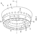
FIG. 3 is a perspective illustration of a combustor. -
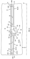
FIG. 4 is a side sectional illustration of a portion of a combustor wall at a quench aperture. -
FIG. 5 is a detailed side sectional illustration of a portion of the combustor wall at the quench aperture. -
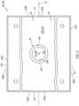
FIG. 6 is a partial illustration of a heat shield tile. -
FIG. 7 is a partial illustration of a deflector at an upstream side of the quench aperture. -
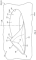
FIG. 8 is a partial perspective illustration of the deflector at the upstream side of the quench aperture. -
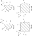
FIGS. 9A and 9B are partial sectional illustrations of a deflector edge with various configurations. -
FIGS. 10A and 10B are partial sectional illustrations of a panel edge with various configurations. -
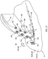
FIG. 11 is a partial perspective schematic illustration of quench air injected into a combustion chamber during turbine engine operation. -
FIG. 1 is a side cutaway illustration of a gearedgas turbine engine 20. Thisturbine engine 20 extends along acenterline axis 22 between anupstream airflow inlet 24 and adownstream airflow exhaust 26. Theturbine engine 20 includes afan section 28, acompressor section 29, acombustor section 30 and aturbine section 31. Thecompressor section 29 includes a low pressure compressor (LPC)section 29A and a high pressure compressor (HPC)section 29B. Theturbine section 31 includes a high pressure turbine (HPT)section 31A and a low pressure turbine (LPT)section 31B. - The engine sections 28-31B are arranged sequentially along the
centerline axis 22 within anengine housing 34. Thisengine housing 34 includes an inner case 36 (e.g., a core case) and an outer case 38 (e.g., a fan case). Theinner case 36 may house one or more of theengine sections 29A-31B; e.g., a core of theturbine engine 20. Theouter case 38 may house at least thefan section 28. - Each of the
engine sections - The
fan rotor 40 is connected to ageartrain 46, for example, through afan shaft 48. Thegeartrain 46 and theLPC rotor 41 are connected to and driven by theLPT rotor 44 through alow speed shaft 49. TheHPC rotor 42 is connected to and driven by theHPT rotor 43 through ahigh speed shaft 50. The shafts 48-50 are rotatably supported by a plurality ofbearings 52; e.g., rolling element and/or thrust bearings. Each of thesebearings 52 is connected to theengine housing 34 by at least one stationary structure such as, for example, an annular support strut. - During operation, air enters the
turbine engine 20 through theairflow inlet 24. This air is directed through thefan section 28 and into acore flowpath 54 and abypass flowpath 56. Thecore flowpath 54 extends sequentially through theengine sections 29A-31B; e.g., the engine core. The air within thecore flowpath 54 may be referred to as "core air". Thebypass flowpath 56 extends through a bypass duct, which bypasses the engine core. The air within thebypass flowpath 56 may be referred to as "bypass air". - The core air is compressed by the
LPC rotor 41 and theHPC rotor 42 and directed into acombustion chamber 58 of acombustor 60 in thecombustor section 30. Fuel is injected into thecombustion chamber 58 and mixed with the compressed core air to provide a fuel-air mixture. This fuel-air mixture is ignited and combustion products thereof flow through and sequentially cause theHPT rotor 43 and theLPT rotor 44 to rotate. The rotation of theHPT rotor 43 and theLPT rotor 44 respectively drive rotation of theHPC rotor 42 and theLPC rotor 41 and, thus, compression of the air received from a core airflow inlet. The rotation of theLPT rotor 44 also drives rotation of thefan rotor 40, which propels the bypass air through and out of thebypass flowpath 56. The propulsion of the bypass air may account for a majority of thrust generated by theturbine engine 20. -
FIG. 2 illustrates a portion of thecombustor section 30 along thecore flowpath 54 between theHPC section 29B and theHPT section 31A. Thiscombustor section 30 includes thecombustor 60, adiffuser plenum 62, one or more fuel injectors 64 (one visible inFIG. 2 ) and one or more igniters 66 (one visible inFIG. 2 ). Briefly, thecombustor 60 is disposed with (e.g., surrounded by) thediffuser plenum 62. Thisdiffuser plenum 62 receives the compressed core air from theHPC section 29B, and provides the received core air for directing into thecombustor 60. In particular, eachfuel injector 64 may include afuel nozzle 68 mated with anair swirler 70. Thefuel nozzle 68 injects the fuel into thecombustion chamber 58. Theair swirler 70 directs some of the core air from thediffuser plenum 62 into thecombustion chamber 58 in a manner that facilitates mixing the core air with the injected fuel. Theigniters 66 ignite the fuel-air mixture within thecombustion chamber 58. One or more quenchapertures FIGS. 3-6 ) in eachcombustor wall combustor 60 may direct additional core air from thediffuser plenum 62 into thecombustion chamber 58 to quench (e.g., stoichiometrically lean) the combustion products; e.g., the ignited fuel-air mixture. With this arrangement, a majority of the compressed core air directed into thecombustion chamber 58 from thediffuser plenum 62 flows through the air swirlers 70 and/or the quenchapertures 72. However, an additional quantity of the compressed core air may be direct into thecombustion chamber 58 from thediffuser plenum 62 through one or more cooling apertures; e.g., seeFIG. 5 . - The
combustor 60 may be configured as an annular combustor; e.g., an annular floating wall combustor. Thecombustor 60 ofFIGS. 2 and3 , for example, includes anannular combustor bulkhead 76, the tubularinner combustor wall 74A ("inner wall") and the tubularouter combustor wall 74B ("outer wall"). Thebulkhead 76 ofFIG. 2 extends radially between and to theinner wall 74A and theouter wall 74B. Thebulkhead 76 may be connected (e.g., mechanically fastened or otherwise attached) to theinner wall 74A and/or theouter wall 74B. Eachcombustor wall 74 projects axially along thecenterline axis 22 out from thebulkhead 76 towards theHPT section 31A. With this arrangement, thecombustion chamber 58 is formed by and extends radially within thecombustor 60 between theinner wall 74A and theouter wall 74B. Thecombustion chamber 58 is formed by and extends axially (in an upstream direction along the core flowpath 54) into thecombustor 60 to thebulkhead 76. Thecombustion chamber 58 also extends within thecombustor 60 circumferentially about (e.g., completely around) thecenterline axis 22, which may configure thecombustion chamber 58 as a full-hoop annulus. - Referring to
FIG. 4 , eachcombustor wall 74 may be configured as a multi-walled structure; e.g., a hollow, dual-walled structure. Thecombustor wall 74 ofFIG. 4 , for example, includes atubular combustor shell 78, a tubularcombustor heat shield 80 and one or more cooling cavities 82 (e.g., impingement cavities) formed by and radially between theshell 78 and theheat shield 80. However, it is contemplated any one or both of thecombustor walls shell 78 is omitted and theheat shield 80 forms a single walled liner / combustor wall. However, for ease of description, eachcombustor wall 74 may be described below as the hollow, dual-walled structure. - Referring to
FIG. 4 , eachcombustor wall 74 may include one or more quench aperture bodies. Each aperture body ofFIG. 4 is configured as an annularheat shield boss 84 connected to and projecting out from a respectiveheat shield panel 86. Thebosses 84 are arranged circumferentially around thecenterline axis 22 in a circular array. Eachboss 84 partially or completely forms a respective quenchaperture 72 in / radially through therespective combustor wall 74. - Referring to
FIG. 2 , theshell 78 extends circumferentially about (e.g., completely around) thecenterline axis 22. Theshell 78 extends axially along thecenterline axis 22 between and to an axialupstream end 88 of theshell 78 and an axialdownstream end 90 of theshell 78. Theshell 78 is connected to thebulkhead 76 at the shellupstream end 88. Theshell 78 may be connected to a stator vane assembly 92 (or a structure of theHPT section 31A) at the shelldownstream end 90. - Referring to
FIG. 5 , theshell 78 extends radially between and to aninterior surface 94 of theshell 78 and anexterior surface 96 of theshell 78. Theshell exterior surface 96 is adjacent and forms a radial peripheral boundary of thediffuser plenum 62. The shellinterior surface 94 is adjacent and forms a radial (e.g., outer or inner) peripheral boundary of each coolingcavity 82. - The
shell 78 may include one or moreshell cooling apertures 98. Each of theseshell cooling apertures 98 may be configured as an impingement aperture. Eachshell cooling aperture 98 ofFIG. 5 , for example, extends (e.g., radially) through theshell 78 from aninlet orifice 100 into the respectiveshell cooling aperture 98 to anoutlet orifice 102 out from the respectiveshell cooling aperture 98. Theinlet orifice 100 is disposed in theshell exterior surface 96. Theoutlet orifice 102 is disposed in the shellinterior surface 94. Theshell cooling apertures 98 thereby fluidly couple thediffuser plenum 62 to each respective coolingcavity 82 within therespective combustor wall 74. Eachshell cooling aperture 98 is also configured to direct a jet of core air into therespective cooling cavity 82 to impinge against thepanel 86. - Referring to
FIG. 2 , theheat shield 80 extends circumferentially about (e.g., completely around) thecenterline axis 22. Theheat shield 80 extends axially along thecenterline axis 22 between and to an axial upstream end of theheat shield 80 and an axial downstream end of theheat shield 80. The heat shield upstream end is located at an interface between therespective combustor wall 74 and thebulkhead 76. The heat shield downstream end may be located at an interface between therespective combustor wall 74 and the stator vane assembly 92 (or the structure of theHPT section 31A). - The
heat shield 80 may include one or moreheat shield tiles tiles centerline axis 22. Theupstream tiles 104A are arranged circumferentially about thecenterline axis 22 and may form an upstream heat shield section / hoop. Thedownstream tiles 104B are arranged circumferentially about thecenterline axis 22 and may form a downstream heat shield section / hoop. Theheat shield 80, however, may alternatively be configured from one or more tubular bodies. - Each tile 104 of
FIGS. 4-6 includes a respective one of thepanels 86 and at least (or only) onewall deflector 106. Each tile 104 may also include one or more tile rails 108A-D (generally referred to as "108") and/or at least (or only) one of thebosses 84. - Referring to
FIGS. 4 and6 , thepanel 86 may be configured as a generally curved (e.g., arcuate) plate. Thepanel 86 ofFIGS. 4 and6 extends axially along thecenterline axis 22 between and to anupstream end 110 of the respective tile 104 and itspanel 86 and adownstream end 112 of the respective tile 104 and itspanel 86. Thepanel 86 ofFIG. 6 extends circumferentially about thecenterline axis 22 between and to opposingcircumferential sides panel 86. Thepanel 86 ofFIG. 5 extends radially between and to aninterior surface 118 of the respective tile 104 and itspanel 86 and an exterior surface 120 of thepanel 86. The panelinterior surface 118 is disposed at (e.g., on, adjacent or proximate) an interior side 122 of the respective tile 104 and itspanel 86. The panelinterior surface 118 ofFIG. 5 , for example, is adjacent and forms a radial (e.g., outer or inner) peripheral boundary of thecombustion chamber 58. The panel exterior surface 120 is disposed at an exterior side 124 of thepanel 86. The panel exterior surface 120 ofFIG. 5 , for example, is adjacent and forms a radial (e.g., inner or outer) peripheral boundary of therespective cooling cavity 82. - The
panel 86 may include one or more of thepanel cooling apertures 126. Each of thesepanel cooling apertures 126 may be configured as an effusion aperture. Eachpanel cooling aperture 126 ofFIG. 5 , for example, extends (e.g., generally radially) through thepanel 86 along acenterline 128 of the respectivepanel cooling aperture 126 from aninlet orifice 130 into the respectivepanel cooling aperture 126 to anoutlet orifice 132 out from the respectivepanel cooling aperture 126. Theinlet orifice 130 is disposed at the panel exterior side 124 in the panel exterior surface 120. Theoutlet orifice 132 is disposed at the panel interior side 122 in the panelinterior surface 118. Thepanel cooling apertures 126 thereby fluidly couple each respective coolingcavity 82 with thecombustion chamber 58. Eachpanel cooling aperture 126 is also configured to direct the core air into therespective combustion chamber 58 to form a film against thepanel 86 and its panelinterior surface 118. To promote formation of the film, the panel coolingaperture centerline 128 may be angularly offset from the panel interior surface 118 (and/or the panel exterior surface 120) by a non-zeroacute angle 134. - Referring to
FIGS. 4 and6 , the tile rails 108 may include one or moreaxial end rails panel 86. Each of these tile rails 108 projects radially out from thepanel 86 and its panel exterior surface 120 to a radialdistal end 136A-D (generally referred to as "136") of the respective tile rail 108. Each of these rail distal ends 136 may be configured to radially engage (e.g., contact, abut against, etc.) theshell 78 and its shellinterior surface 94. - Referring to
FIG. 6 , each of the axial end rails 108A, 108B is disposed at a respective one of the panel ends 110, 112. Each of the axial end rails 108A, 108B extends circumferentially along therespective panel end respective panel side axial end rails cavity 82 extends within therespective combustor wall 74 axially between the respectiveaxial end rails cavity 82 extends within therespective combustor wall 74 circumferentially between the respective circumferential side rails 108C and 108D. Referring toFIG. 5 , each coolingcavity 82 extends within therespective combustor wall 74 radially between the respective panel exterior surface 120 and the shellinterior surface 94. - Referring to
FIG. 6 , theboss 84 may be arranged intermediately (e.g., centered or otherwise positioned) within a respective one of thecooling cavities 82. Theboss 84 ofFIG. 6 , for example, is axially between and axially spaced from the respectiveaxial end rails boss 84 ofFIG. 6 is further circumferentially between and circumferentially spaced from the respective circumferential side rails 108C and 108D. - The
boss 84 ofFIG. 5 is connected to (e.g., formed integral with or otherwise bonded to) thepanel 86. Thisboss 84 projects radially (e.g., along acenterline 138 of a respective quench aperture 72) out from thepanel 86 and its panel exterior surface 120, radially through therespective cooling cavity 82, to a radialdistal end 140 of theboss 84. This bossdistal end 140 may be configured to radially engage (e.g., contact, abut against, etc.) theshell 78 and its shellinterior surface 94. Here, theboss 84 is (e.g., circumferentially and axially) aligned with and extends circumferentially about aport 142 through theshell 78, whichport 142 forms an upstream portion of the respective quenchaperture 72. However, theboss 84 may alternatively project radially into or through theport 142 in other embodiments such that theboss 84 forms the upstream portion of the respective quenchaperture 72. - The
boss 84 ofFIG. 5 extends laterally (e.g., radially relative to the quench aperture centerline 138) between and to a tubular (e.g., cylindrical)inner surface 144 of the respective quenchaperture 72 and a tubular (e.g., cylindrical)outer surface 146 of theboss 84. The apertureinner surface 144 ofFIG. 5 is formed by theboss 84, thepanel 86 and thewall deflector 106. This apertureinner surface 144 may form abore 148 through theheat shield 80, which bore 148 forms a downstream portion of the quenchaperture 72 through therespective combustor wall 74. With this arrangement, the quenchaperture 72 may extend radially (e.g., longitudinally along the quench aperture centerline 138) through therespective combustor wall 74 from an inlet 150 (e.g., an inlet orifice) into the quenchaperture 72 to an outlet 152 (e.g., an orifice orifice) out from the quenchaperture 72. Theaperture inlet 150 ofFIG. 5 is formed by theport 142 and is disposed in theshell exterior surface 96. Theaperture outlet 152 ofFIG. 4 is formed by thebore 148 and is disposed in the panelinterior surface 118 and asurface 154 of thewall deflector 106. For example, an upstream side 156 (e.g., an arcuate leading edge side) of theaperture outlet 152 ofFIG. 5 (e.g., relative to agas flow direction 160 within the combustion chamber 58) as well as a corresponding radially adjacent portion of the apertureinner surface 144 are formed by thewall deflector 106. A downstream side 158 (e.g., an arcuate trailing edge side) of theaperture outlet 152 ofFIG. 5 (e.g., relative to thegas flow direction 160 within the combustion chamber 58) as well as a corresponding radially adjacent portion of the apertureinner surface 144 are formed by thepanel 86. Note, thegas flow direction 160 may include an axial component along thecenterline axis 22 and/or a circumferential component about thecenterline axis 22. A ratio of the axial component to the circumferential component may vary based on combustor flow characteristics. However, it is contemplated the ratio of the axial component to the circumferential component may be less than one (1), equal to one (1) or greater than one (1). The ratio may be less than one where there is relatively high swirl about thecenterline axis 22. The ratio may be greater than one where there is relatively low swirl about thecenterline axis 22. Thus, while theupstream side 156 may be offset (e.g., forward) of thedownstream side 158 along thecenterline axis 22, theupstream side 156 may also be (e.g., clockwise or counterclockwise) offset of thedownstream side 158 about thecenterline axis 22. The present disclosure, however, is not limited to any particular flow direction within thecombustor 60 and itscombustion chamber 58. - The
wall deflector 106 is connected to (e.g., formed integral with or otherwise bonded to) thepanel 86 at the panel interior side 122. Thewall deflector 106 projects (e.g., radially) out from thepanel 86 and its panelinterior surface 118 partially (e.g., slightly) into thecombustion chamber 58 to itsdeflector surface 154. Referring toFIG. 7 , thewall deflector 106 projects longitudinally along thepanel 86 and alongitudinal centerline 162 of thewall deflector 106 from the aperture inner surface 144 (in a direction away from the quenchaperture 72 and its aperture outlet 152) to a distalleading end 164 of thewall deflector 106; e.g., an upstream end of thewall deflector 106 relative to thegas flow direction 160 within thecombustion chamber 58. Thewall deflector 106 extends laterally between and to opposinglateral sides wall deflector 106. Thewall deflector 106 ofFIG. 7 may also extend circumferentially about theaperture outlet 152 more than twenty degrees (20°) between the deflector sides 166 and 168, but less than one-hundred and eighty degrees (180°) for example. Thewall deflector 106 ofFIG. 7 , for example, extends circumferentially about theaperture outlet 152 between sixty or eighty degrees (60°, 80°) and one-hundred and twenty or forty degrees (120°, 140°). - Referring to
FIG. 5 , thewall deflector 106 and itsdeflector surface 154 may form a ramp in the longitudinal direction away from thepanel 86 and its panelinterior surface 118. For example, as thewall deflector 106 extends longitudinally from the quenchaperture 72 and itsaperture outlet 152 to thedeflector leading end 164, thewall deflector 106 ofFIG. 5 (e.g., continuously) tapers towards (e.g., to) thepanel 86 and its panelinterior surface 118. Thedeflector surface 154 ofFIG. 5 thereby slopes to the panelinterior surface 118 at thedeflector leading end 164. Thedeflector surface 154 ofFIG. 5 also slopes away from the panelinterior surface 118 at theaperture outlet 152 / the outletupstream side 156. - Referring to
FIG. 8 , thewall deflector 106 and itsdeflector surface 154 may also or alternatively form a wedge (e.g., a flow splitter) in the lateral direction away from thedeflector centerline 162. For example, as thewall deflector 106 extends laterally to eachdeflector side deflector centerline 162, thewall deflector 106 ofFIG. 8 (e.g., continuously) tapers towards (e.g., to) thepanel 86 and its panelinterior surface 118. Thedeflector surface 154 ofFIG. 8 thereby slopes to the panelinterior surface 118 at eachdeflector side deflector surface 154 ofFIG. 8 also slopes away from the panelinterior surface 118 at or about thedeflector centerline 162. - The
wall deflector 106 and itsdeflector surface 154 may have an apex 170 at (e.g., on, adjacent or proximate) thedeflector centerline 162 and/or theaperture outlet 152 and itsupstream side 156. A peak in thedeflector surface 154 ofFIG. 8 , for example, is (A) disposed on or adjacent an edge 172 (e.g., an exterior corner) of thewall deflector 106 between thedeflector surface 154 and the aperture inner surface 144 (see alsoFIG. 5 ) and (B) laterally aligned with (or passing across) thedeflector centerline 162. - In the longitudinal direction, a geometric slope (e.g., radial rise over longitudinal run) of the taper proximate the
aperture outlet 152 may be greater (e.g., steeper) than a geometric slope of the taper proximate thedeflector leading end 164. Similarly, in the lateral direction, a geometric slope (e.g., radial rise over lateral run) of the taper proximate thedeflector centerline 162 may be greater (e.g., steeper) than a geometric slope of the taper proximate eachdeflector side wall deflector 106. - Referring to
FIG. 9A and 9B , thedeflector surface 154 may be contiguous with and meet the apertureinner surface 144 at thedeflector edge 172 along theupstream side 156 of theaperture outlet 152. Referring toFIG. 9A , thedeflector edge 172 may be configured as a sharp edge. Alternatively, referring toFIG. 9B , thedeflector edge 172 may be configured as an eased edge; e.g., a rounded edge or a beveled edge. Similarly, referring toFIGS. 10A and 10B , the panelinterior surface 118 may be contiguous with and meet the apertureinner surface 144 at anedge 174 of the panel 86 (e.g., an exterior corner) along thedownstream side 158 of theaperture outlet 152. Referring toFIG. 10A , thepanel edge 174 may be configured as a sharp edge. Alternatively, referring toFIG. 10B , thepanel edge 174 may be configured as an eased edge; e.g., a rounded edge or a beveled edge. - With the foregoing arrangement, referring to
FIG. 5 , thedownstream side 158 of theaperture outlet 152 and, thus, the panelinterior surface 118 / the panel interior side 122 are spaced from the panel exterior surface 120 / the panel exterior side 124 by afirst distance 176. Thefirst distance 176 ofFIG. 5 is a thickness of thepanel 86. Theupstream side 156 of theaperture outlet 152 and, thus, thedeflector surface 154 are spaced from the panel exterior surface 120 / the panel exterior side 124 by asecond distance 178. Thesecond distance 178 ofFIG. 5 is a combined thickness of thepanel 86 and thewall deflector 106. Thesecond distance 178 is thereby greater than thefirst distance 176. - Referring to
FIG. 11 , during turbine engine operation, each quenchaperture 72 directs a jet of the quenchair 180 into thecombustion chamber 58 through itsaperture outlet 152. This jet of quenchair 180 penetrates radially into a flow of the combustion products 182 within thecombustion chamber 58. Some of a boundary flow of the combustion products 182 and/or cooling air (e.g., introduced via thepanel cooling apertures 126; seeFIG. 5 ) moving along thecombustor wall 74 is directed laterally around theaperture outlet 152 by thewall deflector 106. Some of the boundary flow of the combustion products 182 and/or the cooling air may also or alternatively be directed radially deeper into thecombustion chamber 58 generally in a direction of the jet of the quenchair 180 by thewall deflector 106. By redirecting the boundary flow of the combustion products 182 and/or the cooling air, thewall deflector 106 may influence (e.g., tailor) one or more vortex systems generated by mixing between the combustion products 182 and the quenchair 180. These vortex systems may include, but are not limited to, aleadingedge vortices 184, lee-side vortices 186,wake vortices 188 and/orhorseshoe vortices 190. This influencing of the vortex system(s) may reduce (e.g., circumferential) variations in downstream mixing and thereby reduce (e.g., circumferential) variations in pattern factor. The influencing of the vortex system(s) may also or alternatively reduce entrainment of combustion products and/or cooling air near thecombustor wall 74 downstream of theaperture outlet 152. Reducing one or more of the foregoing parameters may thereby increase combustion section component and/or turbine section component durability / longevity and/or reduce combustion section cooling requirements and/or turbine section cooling requirements. - In some embodiments, referring to
FIG. 5 , one or more or all of thedeflectors 106 may each be configured with one or more cooling apertures 191 (schematically shown); e.g., effusion apertures. Such cooling aperture(s) 191 may provide and/or extend existing film cooling along thedeflector surface 154. - In some embodiments, one or more protective coatings (e.g., thermal barrier coating(s), etc.) applied to the panel
interior surface 118 may also be applied to one or more portions of eachdeflector 106. The coating(s), for example, may be applied to and cover part or all of thedeflector surface 154. - While the
wall deflectors 106 are described above with respect to the quenchapertures 72, it is contemplated thewall deflectors 106 may also or alternatively be utilized to in conjunction with one or more igniter apertures 192 (seeFIGS. 2 and3 ) through arespective combustor wall 74. The present disclosure therefore is not limited to quench aperture applications, but rather may be utilized for any (e.g., non-cooling hole) wall aperture through arespective combustor wall 74. - The
combustor wall 74 and its wall deflector(s) 106 may be included in various turbine engines other than the one described above. Thecombustor wall 74 and its wall deflector(s) 106, for example, may be included in a geared turbine engine where a geartrain connects one or more shafts to one or more rotors in a fan section, a compressor section and/or any other engine section. Alternatively, thecombustor wall 74 and its wall deflector(s) 106 may be included in a turbine engine configured without a geartrain; e.g., a direct drive turbine engine. Thecombustor wall 74 and its wall deflector(s) 106 may be included in a geared or non-geared turbine engine configured with a single spool, with two spools (e.g., seeFIG. 1 ), or with more than two spools. The turbine engine may be configured as a turbofan engine, a turbojet engine, a turboprop engine, a turboshaft engine, a propfan engine, a pusher fan engine or any other type of turbine engine. The turbine engine may alternatively be configured as an auxiliary power unit (APU) or an industrial gas turbine engine. The present disclosure therefore is not limited to any particular types or configurations of turbine engines. - While various embodiments of the present disclosure have been described, it will be apparent to those of ordinary skill in the art that many more embodiments and implementations are possible within the scope of the disclosure. For example, the present disclosure as described herein includes several aspects and embodiments that include particular features. Although these features may be described individually, it is within the scope of the present disclosure that some or all of these features may be combined with any one of the aspects and remain within the scope of the disclosure. Accordingly, the present disclosure is not to be restricted except in light of the attached claims and their equivalents.
Claims (15)
- An apparatus for a turbine engine (20), comprising:a combustor wall (74) including a panel (86), a deflector (106) and a quench aperture (72) that extends along an aperture centerline (138) through the combustor wall (74) to an aperture outlet (152) into a combustion chamber (58);the panel (86) extending axially along and circumferentially about an axis (22), the panel (86) extending radially between a first panel side (118) and a second panel side (120), the first panel side (118) forming a peripheral boundary of the combustion chamber (58), and the panel (86) forming a downstream side (158) of the aperture outlet (152) at the first panel side (118); andthe deflector (106) projecting out from the panel (86) at the first panel side (118) into the combustion chamber (58), and the deflector (106) forming an upstream side (156) of the aperture outlet (152).
- The apparatus of claim 1, whereinthe deflector (106) projects out from the panel (86) to a deflector surface (154);a tubular surface of the combustor wall (74) forms at least a portion of the quench aperture (72) that extends along the aperture centerline (138) to the aperture outlet (152); andthe tubular surface is contiguous with the deflector surface (154).
- The apparatus of claim 1, whereina tubular surface of the combustor wall (74) forms at least a portion of the quench aperture (72) that extends along the aperture centerline (138) to the aperture outlet (152); andthe tubular surface is formed by the panel (86) and the deflector (106).
- The apparatus of claim 1, 2 or 3, wherein the deflector (106) tapers to the panel (86) as the deflector (106) extends longitudinally away from the aperture outlet (152) to a leading end (164) of the deflector (106).
- The apparatus of claim 4, wherein a slope of the taper proximate the aperture outlet (152) is greater than a slope of the taper proximate the leading end (164) of the deflector (106).
- The apparatus of claim 4 or 5, wherein the deflector (106) tapers to the panel (86) as the deflector (106) extends laterally to a first side (166) of the deflector (106),
wherein, optionally, the deflector (106) tapers to the panel (86) as the deflector (106) extends laterally to a second side (168) of the deflector (106) that is laterally opposite the first side (166) of the deflector (106). - The apparatus of any preceding claim, whereinthe deflector (106) projects out from the panel (86) to a deflector surface (154); andan apex (170) of the deflector surface (154) is located at the upstream side (156) of the aperture outlet (152).
- The apparatus of any preceding claim, wherein the deflector (106) extends circumferentially about the aperture outlet (152) between sixty degrees and one-hundred and forty degrees.
- The apparatus of any preceding claim, wherein the upstream side (156) of the aperture outlet (152) is formed by a sharp edge (172) of the deflector (106).
- The apparatus of any preceding claim, wherein:the downstream side (158) of the aperture outlet (152) is formed by a sharp edge (174) of the panel (86); orthe downstream side (158) of the aperture outlet (152) is formed by an eased edge (174) of the panel (86).
- The apparatus of any preceding claim, whereinthe second panel side (120) is spaced from the aperture outlet (152) along the aperture centerline (138) by a first distance (176) at the downstream side (158) of the aperture outlet (152);the second panel side (120) is spaced from the aperture outlet (152) along the aperture centerline (138) by a second distance (178) at the upstream side (156) of the aperture outlet (152); andthe second distance (178) is greater than the first distance (176).
- The apparatus of any preceding claim, wherein:the combustor wall (74) further includes a boss (84);the boss (84) projects out from the panel (86) at the second panel side (120); andthe boss (84) extends circumferentially around and forms an outer peripheral boundary of the quench aperture (72) within the combustor wall (74),wherein, optionally:the combustor wall (74) further includes a heat shield (80) and a shell (78);the heat shield (80) includes the panel (86), the deflector (106) and the boss (84), and the heat shield (80) is attached to the shell (78); andthe boss (84) projects out from the panel (86) to a distal end (140) of the boss (84), and the distal end (140) engages the shell (78).
- The apparatus of any preceding claim, wherein the combustor wall (74) further includes one or more cooling apertures projecting through the panel (86).
- An apparatus for a turbine engine (20), comprising:a combustor wall (74) including a panel (86), a deflector (106), a plurality of cooling apertures and a wall aperture (72) that extends along an aperture centerline (138) through the combustor wall (74) to an aperture outlet (152) into a combustion chamber (58);the panel (86) extending axially along and circumferentially about an axis (22), the panel (86) extending radially between a first panel surface (118) and a second panel surface (120), and the first panel surface (118) forming a peripheral boundary of the combustion chamber (58);the deflector (106) projecting radially out from the panel (86) into the combustion chamber (58) to a deflector surface (154), the deflector (106) partially forming the aperture outlet (152), and the deflector surface (154) sloping to the first panel surface (118) as the deflector (106) extends longitudinally from the aperture outlet (152); andthe plurality of cooling apertures projecting through the panel (86),wherein, optionally:the wall aperture comprises a quench aperture (72); and/orthe panel (86) forms a trailing edge side (158) of the aperture outlet (152) relative to flow (160) within the combustion chamber (58), and the deflector (106) forms a leading edge side (156) of the aperture outlet (152) relative to the flow (160) within the combustion chamber (58).
- An apparatus for a turbine engine (20), comprising:a combustor wall (74) including a panel (86), a deflector (106) and a quench aperture (72) that extends along an aperture centerline (138) through the combustor wall (74) to an aperture outlet (152) into a combustion chamber (58);the panel (86) extending axially along and circumferentially about an axis (22), the panel (86) extending radially between a first panel side (118) and a second panel side (120), the first panel side (118) forming a peripheral boundary of the combustion chamber (58); andthe deflector (106) integral with the panel (86), the deflector (106) projecting out from the panel (86) at the first panel side (118) into the combustion chamber (58), the deflector (106) forming the aperture outlet (152) with the panel (86), and the deflector (106) tapering towards the panel (86) as the deflector (106) projects longitudinally away from the aperture outlet (152).
Applications Claiming Priority (1)
| Application Number | Priority Date | Filing Date | Title |
|---|---|---|---|
| US18/117,924 US20240302042A1 (en) | 2023-03-06 | 2023-03-06 | Turbine engine combustor wall with aperture deflector |
Publications (2)
| Publication Number | Publication Date |
|---|---|
| EP4428442A1 true EP4428442A1 (en) | 2024-09-11 |
| EP4428442B1 EP4428442B1 (en) | 2025-12-03 |
Family
ID=90362928
Family Applications (1)
| Application Number | Title | Priority Date | Filing Date |
|---|---|---|---|
| EP24161870.1A Active EP4428442B1 (en) | 2023-03-06 | 2024-03-06 | Turbine engine combustor wall with aperture deflector |
Country Status (2)
| Country | Link |
|---|---|
| US (1) | US20240302042A1 (en) |
| EP (1) | EP4428442B1 (en) |
Citations (5)
| Publication number | Priority date | Publication date | Assignee | Title |
|---|---|---|---|---|
| US2541171A (en) * | 1947-01-25 | 1951-02-13 | Kellogg M W Co | Air inlet structure for combustion chambers |
| US20070227149A1 (en) * | 2006-03-30 | 2007-10-04 | Snecma | Configuration of dilution openings in a turbomachine combustion chamber wall |
| US20170370588A1 (en) * | 2016-06-22 | 2017-12-28 | General Electric Company | Combustor assembly for a turbine engine |
| US20200208840A1 (en) * | 2018-12-27 | 2020-07-02 | Rolls-Royce Corporation | Alm enabled combustion liner assembly |
| US20230044804A1 (en) * | 2021-08-03 | 2023-02-09 | Pratt & Whitney Canada Corp. | Combustor with dilution holes |
Family Cites Families (1)
| Publication number | Priority date | Publication date | Assignee | Title |
|---|---|---|---|---|
| EP2946145B1 (en) * | 2013-01-16 | 2020-07-15 | United Technologies Corporation | Combustor cooled quench zone array |
-
2023
- 2023-03-06 US US18/117,924 patent/US20240302042A1/en active Pending
-
2024
- 2024-03-06 EP EP24161870.1A patent/EP4428442B1/en active Active
Patent Citations (5)
| Publication number | Priority date | Publication date | Assignee | Title |
|---|---|---|---|---|
| US2541171A (en) * | 1947-01-25 | 1951-02-13 | Kellogg M W Co | Air inlet structure for combustion chambers |
| US20070227149A1 (en) * | 2006-03-30 | 2007-10-04 | Snecma | Configuration of dilution openings in a turbomachine combustion chamber wall |
| US20170370588A1 (en) * | 2016-06-22 | 2017-12-28 | General Electric Company | Combustor assembly for a turbine engine |
| US20200208840A1 (en) * | 2018-12-27 | 2020-07-02 | Rolls-Royce Corporation | Alm enabled combustion liner assembly |
| US20230044804A1 (en) * | 2021-08-03 | 2023-02-09 | Pratt & Whitney Canada Corp. | Combustor with dilution holes |
Also Published As
| Publication number | Publication date |
|---|---|
| EP4428442B1 (en) | 2025-12-03 |
| US20240302042A1 (en) | 2024-09-12 |
Similar Documents
| Publication | Publication Date | Title |
|---|---|---|
| CN109668174B (en) | Trapped vortex combustor for gas turbine engine and method of operation | |
| US11788725B2 (en) | Trapped vortex combustor for a gas turbine engine with a driver airflow channel | |
| CN114857618B (en) | Combustor for a gas turbine engine | |
| US11892165B2 (en) | Heat shield for fuel nozzle | |
| US12152779B1 (en) | Combustor | |
| EP3601887B1 (en) | Minimization of low pressure vortex in the rail between two adjacent liner panels | |
| EP3040524B1 (en) | Outer diffuser case for a gas turbine engine | |
| EP4417868B1 (en) | Cooling combustor wall boss | |
| EP3321584B1 (en) | Gas turbine engine combustor with an axially non-planar combustor liner panel | |
| US12410916B2 (en) | Annular dome assembly for a combustor | |
| EP4421389B1 (en) | Fuel injector air swirler structure with canted flow guide surface | |
| EP4428442B1 (en) | Turbine engine combustor wall with aperture deflector | |
| US12305571B2 (en) | Combustor | |
| EP4310299B1 (en) | Flow deflector for aperture in gas turbine engine flowpath wall | |
| EP4317784A1 (en) | Swirler with recessed fuel filmer and air assist fuel nozzle | |
| US12044172B2 (en) | Air guide for a gas turbine engine | |
| EP4513089B1 (en) | Combustor | |
| EP4421387A1 (en) | Turbine engine fuel injector assembly with annular fuel outlet | |
| US20240159398A1 (en) | Fuel injector assembly for gas turbine engine | |
| US20260063296A1 (en) | Spill return fuel nozzles for usage as start nozzles |
Legal Events
| Date | Code | Title | Description |
|---|---|---|---|
| PUAI | Public reference made under article 153(3) epc to a published international application that has entered the european phase |
Free format text: ORIGINAL CODE: 0009012 |
|
| STAA | Information on the status of an ep patent application or granted ep patent |
Free format text: STATUS: THE APPLICATION HAS BEEN PUBLISHED |
|
| AK | Designated contracting states |
Kind code of ref document: A1 Designated state(s): AL AT BE BG CH CY CZ DE DK EE ES FI FR GB GR HR HU IE IS IT LI LT LU LV MC ME MK MT NL NO PL PT RO RS SE SI SK SM TR |
|
| STAA | Information on the status of an ep patent application or granted ep patent |
Free format text: STATUS: REQUEST FOR EXAMINATION WAS MADE |
|
| 17P | Request for examination filed |
Effective date: 20250311 |
|
| GRAP | Despatch of communication of intention to grant a patent |
Free format text: ORIGINAL CODE: EPIDOSNIGR1 |
|
| STAA | Information on the status of an ep patent application or granted ep patent |
Free format text: STATUS: GRANT OF PATENT IS INTENDED |
|
| INTG | Intention to grant announced |
Effective date: 20250704 |
|
| GRAS | Grant fee paid |
Free format text: ORIGINAL CODE: EPIDOSNIGR3 |
|
| GRAA | (expected) grant |
Free format text: ORIGINAL CODE: 0009210 |
|
| STAA | Information on the status of an ep patent application or granted ep patent |
Free format text: STATUS: THE PATENT HAS BEEN GRANTED |
|
| AK | Designated contracting states |
Kind code of ref document: B1 Designated state(s): AL AT BE BG CH CY CZ DE DK EE ES FI FR GB GR HR HU IE IS IT LI LT LU LV MC ME MK MT NL NO PL PT RO RS SE SI SK SM TR |
|
| REG | Reference to a national code |
Ref country code: CH Ref legal event code: F10 Free format text: ST27 STATUS EVENT CODE: U-0-0-F10-F00 (AS PROVIDED BY THE NATIONAL OFFICE) Effective date: 20251203 Ref country code: GB Ref legal event code: FG4D |
|
| REG | Reference to a national code |
Ref country code: DE Ref legal event code: R096 Ref document number: 602024001466 Country of ref document: DE |
|
| REG | Reference to a national code |
Ref country code: IE Ref legal event code: FG4D |
|
| REG | Reference to a national code |
Ref country code: NL Ref legal event code: MP Effective date: 20251203 |
|
| PG25 | Lapsed in a contracting state [announced via postgrant information from national office to epo] |
Ref country code: ES Free format text: LAPSE BECAUSE OF FAILURE TO SUBMIT A TRANSLATION OF THE DESCRIPTION OR TO PAY THE FEE WITHIN THE PRESCRIBED TIME-LIMIT Effective date: 20251203 |
|
| REG | Reference to a national code |
Ref country code: LT Ref legal event code: MG9D |
|
| PG25 | Lapsed in a contracting state [announced via postgrant information from national office to epo] |
Ref country code: NO Free format text: LAPSE BECAUSE OF FAILURE TO SUBMIT A TRANSLATION OF THE DESCRIPTION OR TO PAY THE FEE WITHIN THE PRESCRIBED TIME-LIMIT Effective date: 20260303 |
|
| PGFP | Annual fee paid to national office [announced via postgrant information from national office to epo] |
Ref country code: DE Payment date: 20260219 Year of fee payment: 3 |
|
| PG25 | Lapsed in a contracting state [announced via postgrant information from national office to epo] |
Ref country code: FI Free format text: LAPSE BECAUSE OF FAILURE TO SUBMIT A TRANSLATION OF THE DESCRIPTION OR TO PAY THE FEE WITHIN THE PRESCRIBED TIME-LIMIT Effective date: 20251203 Ref country code: HR Free format text: LAPSE BECAUSE OF FAILURE TO SUBMIT A TRANSLATION OF THE DESCRIPTION OR TO PAY THE FEE WITHIN THE PRESCRIBED TIME-LIMIT Effective date: 20251203 |
|
| PGFP | Annual fee paid to national office [announced via postgrant information from national office to epo] |
Ref country code: AT Payment date: 20260301 Year of fee payment: 3 |
|
| PG25 | Lapsed in a contracting state [announced via postgrant information from national office to epo] |
Ref country code: RS Free format text: LAPSE BECAUSE OF FAILURE TO SUBMIT A TRANSLATION OF THE DESCRIPTION OR TO PAY THE FEE WITHIN THE PRESCRIBED TIME-LIMIT Effective date: 20260303 |
|
| PGFP | Annual fee paid to national office [announced via postgrant information from national office to epo] |
Ref country code: FR Payment date: 20260219 Year of fee payment: 3 |
|
| PG25 | Lapsed in a contracting state [announced via postgrant information from national office to epo] |
Ref country code: PL Free format text: LAPSE BECAUSE OF FAILURE TO SUBMIT A TRANSLATION OF THE DESCRIPTION OR TO PAY THE FEE WITHIN THE PRESCRIBED TIME-LIMIT Effective date: 20251203 |
|
| PG25 | Lapsed in a contracting state [announced via postgrant information from national office to epo] |
Ref country code: LV Free format text: LAPSE BECAUSE OF FAILURE TO SUBMIT A TRANSLATION OF THE DESCRIPTION OR TO PAY THE FEE WITHIN THE PRESCRIBED TIME-LIMIT Effective date: 20251203 |
|
| PG25 | Lapsed in a contracting state [announced via postgrant information from national office to epo] |
Ref country code: BG Free format text: LAPSE BECAUSE OF FAILURE TO SUBMIT A TRANSLATION OF THE DESCRIPTION OR TO PAY THE FEE WITHIN THE PRESCRIBED TIME-LIMIT Effective date: 20251203 |