EP4428434A1 - Signaling device for a vehicle - Google Patents
Signaling device for a vehicle Download PDFInfo
- Publication number
- EP4428434A1 EP4428434A1 EP23160752.4A EP23160752A EP4428434A1 EP 4428434 A1 EP4428434 A1 EP 4428434A1 EP 23160752 A EP23160752 A EP 23160752A EP 4428434 A1 EP4428434 A1 EP 4428434A1
- Authority
- EP
- European Patent Office
- Prior art keywords
- optical element
- light source
- light
- holding frame
- lighting device
- Prior art date
- Legal status (The legal status is an assumption and is not a legal conclusion. Google has not performed a legal analysis and makes no representation as to the accuracy of the status listed.)
- Pending
Links
Images
Classifications
-
- F—MECHANICAL ENGINEERING; LIGHTING; HEATING; WEAPONS; BLASTING
- F21—LIGHTING
- F21S—NON-PORTABLE LIGHTING DEVICES; SYSTEMS THEREOF; VEHICLE LIGHTING DEVICES SPECIALLY ADAPTED FOR VEHICLE EXTERIORS
- F21S41/00—Illuminating devices specially adapted for vehicle exteriors, e.g. headlamps
- F21S41/10—Illuminating devices specially adapted for vehicle exteriors, e.g. headlamps characterised by the light source
- F21S41/19—Attachment of light sources or lamp holders
- F21S41/192—Details of lamp holders, terminals or connectors
-
- F—MECHANICAL ENGINEERING; LIGHTING; HEATING; WEAPONS; BLASTING
- F21—LIGHTING
- F21S—NON-PORTABLE LIGHTING DEVICES; SYSTEMS THEREOF; VEHICLE LIGHTING DEVICES SPECIALLY ADAPTED FOR VEHICLE EXTERIORS
- F21S43/00—Signalling devices specially adapted for vehicle exteriors, e.g. brake lamps, direction indicator lights or reversing lights
- F21S43/20—Signalling devices specially adapted for vehicle exteriors, e.g. brake lamps, direction indicator lights or reversing lights characterised by refractors, transparent cover plates, light guides or filters
- F21S43/235—Light guides
- F21S43/242—Light guides characterised by the emission area
- F21S43/245—Light guides characterised by the emission area emitting light from one or more of its major surfaces
-
- F—MECHANICAL ENGINEERING; LIGHTING; HEATING; WEAPONS; BLASTING
- F21—LIGHTING
- F21S—NON-PORTABLE LIGHTING DEVICES; SYSTEMS THEREOF; VEHICLE LIGHTING DEVICES SPECIALLY ADAPTED FOR VEHICLE EXTERIORS
- F21S43/00—Signalling devices specially adapted for vehicle exteriors, e.g. brake lamps, direction indicator lights or reversing lights
- F21S43/20—Signalling devices specially adapted for vehicle exteriors, e.g. brake lamps, direction indicator lights or reversing lights characterised by refractors, transparent cover plates, light guides or filters
- F21S43/235—Light guides
- F21S43/236—Light guides characterised by the shape of the light guide
- F21S43/241—Light guides characterised by the shape of the light guide of complex shape
-
- F—MECHANICAL ENGINEERING; LIGHTING; HEATING; WEAPONS; BLASTING
- F21—LIGHTING
- F21S—NON-PORTABLE LIGHTING DEVICES; SYSTEMS THEREOF; VEHICLE LIGHTING DEVICES SPECIALLY ADAPTED FOR VEHICLE EXTERIORS
- F21S41/00—Illuminating devices specially adapted for vehicle exteriors, e.g. headlamps
- F21S41/10—Illuminating devices specially adapted for vehicle exteriors, e.g. headlamps characterised by the light source
-
- F—MECHANICAL ENGINEERING; LIGHTING; HEATING; WEAPONS; BLASTING
- F21—LIGHTING
- F21S—NON-PORTABLE LIGHTING DEVICES; SYSTEMS THEREOF; VEHICLE LIGHTING DEVICES SPECIALLY ADAPTED FOR VEHICLE EXTERIORS
- F21S41/00—Illuminating devices specially adapted for vehicle exteriors, e.g. headlamps
- F21S41/20—Illuminating devices specially adapted for vehicle exteriors, e.g. headlamps characterised by refractors, transparent cover plates, light guides or filters
- F21S41/24—Light guides
-
- F—MECHANICAL ENGINEERING; LIGHTING; HEATING; WEAPONS; BLASTING
- F21—LIGHTING
- F21S—NON-PORTABLE LIGHTING DEVICES; SYSTEMS THEREOF; VEHICLE LIGHTING DEVICES SPECIALLY ADAPTED FOR VEHICLE EXTERIORS
- F21S41/00—Illuminating devices specially adapted for vehicle exteriors, e.g. headlamps
- F21S41/20—Illuminating devices specially adapted for vehicle exteriors, e.g. headlamps characterised by refractors, transparent cover plates, light guides or filters
- F21S41/25—Projection lenses
- F21S41/265—Composite lenses; Lenses with a patch-like shape
-
- F—MECHANICAL ENGINEERING; LIGHTING; HEATING; WEAPONS; BLASTING
- F21—LIGHTING
- F21S—NON-PORTABLE LIGHTING DEVICES; SYSTEMS THEREOF; VEHICLE LIGHTING DEVICES SPECIALLY ADAPTED FOR VEHICLE EXTERIORS
- F21S41/00—Illuminating devices specially adapted for vehicle exteriors, e.g. headlamps
- F21S41/20—Illuminating devices specially adapted for vehicle exteriors, e.g. headlamps characterised by refractors, transparent cover plates, light guides or filters
- F21S41/29—Attachment thereof
-
- F—MECHANICAL ENGINEERING; LIGHTING; HEATING; WEAPONS; BLASTING
- F21—LIGHTING
- F21S—NON-PORTABLE LIGHTING DEVICES; SYSTEMS THEREOF; VEHICLE LIGHTING DEVICES SPECIALLY ADAPTED FOR VEHICLE EXTERIORS
- F21S41/00—Illuminating devices specially adapted for vehicle exteriors, e.g. headlamps
- F21S41/30—Illuminating devices specially adapted for vehicle exteriors, e.g. headlamps characterised by reflectors
- F21S41/32—Optical layout thereof
- F21S41/322—Optical layout thereof the reflector using total internal reflection
-
- F—MECHANICAL ENGINEERING; LIGHTING; HEATING; WEAPONS; BLASTING
- F21—LIGHTING
- F21S—NON-PORTABLE LIGHTING DEVICES; SYSTEMS THEREOF; VEHICLE LIGHTING DEVICES SPECIALLY ADAPTED FOR VEHICLE EXTERIORS
- F21S41/00—Illuminating devices specially adapted for vehicle exteriors, e.g. headlamps
- F21S41/60—Illuminating devices specially adapted for vehicle exteriors, e.g. headlamps characterised by a variable light distribution
- F21S41/65—Illuminating devices specially adapted for vehicle exteriors, e.g. headlamps characterised by a variable light distribution by acting on light sources
- F21S41/663—Illuminating devices specially adapted for vehicle exteriors, e.g. headlamps characterised by a variable light distribution by acting on light sources by switching light sources
-
- F—MECHANICAL ENGINEERING; LIGHTING; HEATING; WEAPONS; BLASTING
- F21—LIGHTING
- F21S—NON-PORTABLE LIGHTING DEVICES; SYSTEMS THEREOF; VEHICLE LIGHTING DEVICES SPECIALLY ADAPTED FOR VEHICLE EXTERIORS
- F21S43/00—Signalling devices specially adapted for vehicle exteriors, e.g. brake lamps, direction indicator lights or reversing lights
- F21S43/10—Signalling devices specially adapted for vehicle exteriors, e.g. brake lamps, direction indicator lights or reversing lights characterised by the light source
- F21S43/13—Signalling devices specially adapted for vehicle exteriors, e.g. brake lamps, direction indicator lights or reversing lights characterised by the light source characterised by the type of light source
- F21S43/14—Light emitting diodes [LED]
-
- F—MECHANICAL ENGINEERING; LIGHTING; HEATING; WEAPONS; BLASTING
- F21—LIGHTING
- F21S—NON-PORTABLE LIGHTING DEVICES; SYSTEMS THEREOF; VEHICLE LIGHTING DEVICES SPECIALLY ADAPTED FOR VEHICLE EXTERIORS
- F21S43/00—Signalling devices specially adapted for vehicle exteriors, e.g. brake lamps, direction indicator lights or reversing lights
- F21S43/10—Signalling devices specially adapted for vehicle exteriors, e.g. brake lamps, direction indicator lights or reversing lights characterised by the light source
- F21S43/13—Signalling devices specially adapted for vehicle exteriors, e.g. brake lamps, direction indicator lights or reversing lights characterised by the light source characterised by the type of light source
- F21S43/15—Strips of light sources
-
- F—MECHANICAL ENGINEERING; LIGHTING; HEATING; WEAPONS; BLASTING
- F21—LIGHTING
- F21S—NON-PORTABLE LIGHTING DEVICES; SYSTEMS THEREOF; VEHICLE LIGHTING DEVICES SPECIALLY ADAPTED FOR VEHICLE EXTERIORS
- F21S43/00—Signalling devices specially adapted for vehicle exteriors, e.g. brake lamps, direction indicator lights or reversing lights
- F21S43/10—Signalling devices specially adapted for vehicle exteriors, e.g. brake lamps, direction indicator lights or reversing lights characterised by the light source
- F21S43/19—Attachment of light sources or lamp holders
-
- F—MECHANICAL ENGINEERING; LIGHTING; HEATING; WEAPONS; BLASTING
- F21—LIGHTING
- F21S—NON-PORTABLE LIGHTING DEVICES; SYSTEMS THEREOF; VEHICLE LIGHTING DEVICES SPECIALLY ADAPTED FOR VEHICLE EXTERIORS
- F21S43/00—Signalling devices specially adapted for vehicle exteriors, e.g. brake lamps, direction indicator lights or reversing lights
- F21S43/10—Signalling devices specially adapted for vehicle exteriors, e.g. brake lamps, direction indicator lights or reversing lights characterised by the light source
- F21S43/19—Attachment of light sources or lamp holders
- F21S43/195—Details of lamp holders, terminals or connectors
-
- F—MECHANICAL ENGINEERING; LIGHTING; HEATING; WEAPONS; BLASTING
- F21—LIGHTING
- F21S—NON-PORTABLE LIGHTING DEVICES; SYSTEMS THEREOF; VEHICLE LIGHTING DEVICES SPECIALLY ADAPTED FOR VEHICLE EXTERIORS
- F21S43/00—Signalling devices specially adapted for vehicle exteriors, e.g. brake lamps, direction indicator lights or reversing lights
- F21S43/20—Signalling devices specially adapted for vehicle exteriors, e.g. brake lamps, direction indicator lights or reversing lights characterised by refractors, transparent cover plates, light guides or filters
- F21S43/235—Light guides
-
- F—MECHANICAL ENGINEERING; LIGHTING; HEATING; WEAPONS; BLASTING
- F21—LIGHTING
- F21S—NON-PORTABLE LIGHTING DEVICES; SYSTEMS THEREOF; VEHICLE LIGHTING DEVICES SPECIALLY ADAPTED FOR VEHICLE EXTERIORS
- F21S43/00—Signalling devices specially adapted for vehicle exteriors, e.g. brake lamps, direction indicator lights or reversing lights
- F21S43/20—Signalling devices specially adapted for vehicle exteriors, e.g. brake lamps, direction indicator lights or reversing lights characterised by refractors, transparent cover plates, light guides or filters
- F21S43/235—Light guides
- F21S43/236—Light guides characterised by the shape of the light guide
- F21S43/239—Light guides characterised by the shape of the light guide plate-shaped
-
- F—MECHANICAL ENGINEERING; LIGHTING; HEATING; WEAPONS; BLASTING
- F21—LIGHTING
- F21S—NON-PORTABLE LIGHTING DEVICES; SYSTEMS THEREOF; VEHICLE LIGHTING DEVICES SPECIALLY ADAPTED FOR VEHICLE EXTERIORS
- F21S43/00—Signalling devices specially adapted for vehicle exteriors, e.g. brake lamps, direction indicator lights or reversing lights
- F21S43/20—Signalling devices specially adapted for vehicle exteriors, e.g. brake lamps, direction indicator lights or reversing lights characterised by refractors, transparent cover plates, light guides or filters
- F21S43/235—Light guides
- F21S43/242—Light guides characterised by the emission area
- F21S43/243—Light guides characterised by the emission area emitting light from one or more of its extremities
-
- F—MECHANICAL ENGINEERING; LIGHTING; HEATING; WEAPONS; BLASTING
- F21—LIGHTING
- F21S—NON-PORTABLE LIGHTING DEVICES; SYSTEMS THEREOF; VEHICLE LIGHTING DEVICES SPECIALLY ADAPTED FOR VEHICLE EXTERIORS
- F21S43/00—Signalling devices specially adapted for vehicle exteriors, e.g. brake lamps, direction indicator lights or reversing lights
- F21S43/20—Signalling devices specially adapted for vehicle exteriors, e.g. brake lamps, direction indicator lights or reversing lights characterised by refractors, transparent cover plates, light guides or filters
- F21S43/235—Light guides
- F21S43/249—Light guides with two or more light sources being coupled into the light guide
-
- F—MECHANICAL ENGINEERING; LIGHTING; HEATING; WEAPONS; BLASTING
- F21—LIGHTING
- F21S—NON-PORTABLE LIGHTING DEVICES; SYSTEMS THEREOF; VEHICLE LIGHTING DEVICES SPECIALLY ADAPTED FOR VEHICLE EXTERIORS
- F21S43/00—Signalling devices specially adapted for vehicle exteriors, e.g. brake lamps, direction indicator lights or reversing lights
- F21S43/20—Signalling devices specially adapted for vehicle exteriors, e.g. brake lamps, direction indicator lights or reversing lights characterised by refractors, transparent cover plates, light guides or filters
- F21S43/235—Light guides
- F21S43/253—Two or more juxtaposed light guides
-
- F—MECHANICAL ENGINEERING; LIGHTING; HEATING; WEAPONS; BLASTING
- F21—LIGHTING
- F21S—NON-PORTABLE LIGHTING DEVICES; SYSTEMS THEREOF; VEHICLE LIGHTING DEVICES SPECIALLY ADAPTED FOR VEHICLE EXTERIORS
- F21S43/00—Signalling devices specially adapted for vehicle exteriors, e.g. brake lamps, direction indicator lights or reversing lights
- F21S43/20—Signalling devices specially adapted for vehicle exteriors, e.g. brake lamps, direction indicator lights or reversing lights characterised by refractors, transparent cover plates, light guides or filters
- F21S43/2605—Refractors
- F21S43/2621—Refractors characterised by the properties of the light beam shaping surface
- F21S43/26271—Refractors characterised by the properties of the light beam shaping surface using micro-optics, e.g. micro-lenses or micro-structures
-
- F—MECHANICAL ENGINEERING; LIGHTING; HEATING; WEAPONS; BLASTING
- F21—LIGHTING
- F21S—NON-PORTABLE LIGHTING DEVICES; SYSTEMS THEREOF; VEHICLE LIGHTING DEVICES SPECIALLY ADAPTED FOR VEHICLE EXTERIORS
- F21S43/00—Signalling devices specially adapted for vehicle exteriors, e.g. brake lamps, direction indicator lights or reversing lights
- F21S43/20—Signalling devices specially adapted for vehicle exteriors, e.g. brake lamps, direction indicator lights or reversing lights characterised by refractors, transparent cover plates, light guides or filters
- F21S43/27—Attachment thereof
-
- F—MECHANICAL ENGINEERING; LIGHTING; HEATING; WEAPONS; BLASTING
- F21—LIGHTING
- F21S—NON-PORTABLE LIGHTING DEVICES; SYSTEMS THEREOF; VEHICLE LIGHTING DEVICES SPECIALLY ADAPTED FOR VEHICLE EXTERIORS
- F21S45/00—Arrangements within vehicle lighting devices specially adapted for vehicle exteriors, for purposes other than emission or distribution of light
- F21S45/40—Cooling of lighting devices
- F21S45/47—Passive cooling, e.g. using fins, thermal conductive elements or openings
-
- B—PERFORMING OPERATIONS; TRANSPORTING
- B60—VEHICLES IN GENERAL
- B60Q—ARRANGEMENT OF SIGNALLING OR LIGHTING DEVICES, THE MOUNTING OR SUPPORTING THEREOF OR CIRCUITS THEREFOR, FOR VEHICLES IN GENERAL
- B60Q2400/00—Special features or arrangements of exterior signal lamps for vehicles
- B60Q2400/20—Multi-color single source or LED matrix, e.g. yellow blinker and red brake lamp generated by single lamp
-
- F—MECHANICAL ENGINEERING; LIGHTING; HEATING; WEAPONS; BLASTING
- F21—LIGHTING
- F21W—INDEXING SCHEME ASSOCIATED WITH SUBCLASSES F21K, F21L, F21S and F21V, RELATING TO USES OR APPLICATIONS OF LIGHTING DEVICES OR SYSTEMS
- F21W2102/00—Exterior vehicle lighting devices for illuminating purposes
-
- F—MECHANICAL ENGINEERING; LIGHTING; HEATING; WEAPONS; BLASTING
- F21—LIGHTING
- F21W—INDEXING SCHEME ASSOCIATED WITH SUBCLASSES F21K, F21L, F21S and F21V, RELATING TO USES OR APPLICATIONS OF LIGHTING DEVICES OR SYSTEMS
- F21W2103/00—Exterior vehicle lighting devices for signalling purposes
-
- F—MECHANICAL ENGINEERING; LIGHTING; HEATING; WEAPONS; BLASTING
- F21—LIGHTING
- F21W—INDEXING SCHEME ASSOCIATED WITH SUBCLASSES F21K, F21L, F21S and F21V, RELATING TO USES OR APPLICATIONS OF LIGHTING DEVICES OR SYSTEMS
- F21W2103/00—Exterior vehicle lighting devices for signalling purposes
- F21W2103/10—Position lights
-
- F—MECHANICAL ENGINEERING; LIGHTING; HEATING; WEAPONS; BLASTING
- F21—LIGHTING
- F21W—INDEXING SCHEME ASSOCIATED WITH SUBCLASSES F21K, F21L, F21S and F21V, RELATING TO USES OR APPLICATIONS OF LIGHTING DEVICES OR SYSTEMS
- F21W2103/00—Exterior vehicle lighting devices for signalling purposes
- F21W2103/20—Direction indicator lights
-
- F—MECHANICAL ENGINEERING; LIGHTING; HEATING; WEAPONS; BLASTING
- F21—LIGHTING
- F21W—INDEXING SCHEME ASSOCIATED WITH SUBCLASSES F21K, F21L, F21S and F21V, RELATING TO USES OR APPLICATIONS OF LIGHTING DEVICES OR SYSTEMS
- F21W2107/00—Use or application of lighting devices on or in particular types of vehicles
- F21W2107/10—Use or application of lighting devices on or in particular types of vehicles for land vehicles
Definitions
- the invention relates to a lighting device for a vehicle, said lighting device is configured to create a segmented light function, in particular a segmented signal light, composed of at least two segments, said lighting device comprises:
- the invention also relates to a vehicle lamp, in particular a vehicle turn signal lamp, a vehicle headlamp or a vehicle taillamp, comprising a lighting device.
- each segment of the segmented light function is created by a specific optical element (e.g. thick wall optics, which guide light via total internal reflexion towards a light emitting surface of the thick wall optic).
- a specific optical element e.g. thick wall optics, which guide light via total internal reflexion towards a light emitting surface of the thick wall optic.
- blinds and shielding elements make the entire lighting device more complex and such parts are difficult to apply and fixate in a vehicle lamp, because vehicle lamps are subject to vibrations and other mechanical forces.
- the alternative of having a rather large gap between individual optical elements deteriorates the optical impression of a holistic light function, which is being compiled of multiple segments.
- the first optical element comprises a first protrusion, extending away from the lateral surface of the first optical element
- the second optical element comprises at least one second protrusion, extending away from the lateral surface of the second optical element
- first optical element and the second optical element are both secured (or fixed) along the direction of light propagation (the main beam direction), along a direction opposite to the direction of light propagation, and also along a (essentially vertical) plane, which is perpendicular to the direction of light propagation.
- the mounting position can be established in a convenient way, because the first optical element and the second optical element can slide along the main beam direction within the confined space defined by the frame element (which can also be described as a longitudinal hull or shell element) in order to arrive at the mounting position.
- the first receiving element, the second receiving element, the first stopping element, the second stopping and the cover element together advantageously provide a fixation of the first optical element and the second optical element within the frame element.
- the lateral surface of the first optical element limits the first optical element in a direction orthogonal to the main beam direction
- the later surface of the second optical element limits the second optical element in a direction orthogonal to the main beam direction.
- the lighting device may comprise a third or more optical elements, wherein these additional optical elements may comprise protrusions equivalent to the first protrusion of the first optical element
- the frame element may comprise additional receiving elements, wherein each receiving element corresponds to a specific protrusion of a corresponding optical element.
- Each optical element may comprise two or more protrusions, wherein the frame element may comprise multiple receiving elements, wherein each receiving element corresponds to a specific protrusion and is configured to engage with its corresponding protrusion.
- the holding frame further comprises at least one, preferably multiple, distance element, wherein in the mounting position the distance element is disposed at least partially between the first optical element and the second optical element and/or between the first optical element and the holding frame and/or between the second optical element and the holding frame, wherein the at least one distance element is configured to keep the gap between the first optical element and the second optical element and/or between the first optical element and the holding frame and/or between the second optical element and the holding frame, constant along the longitudinal extension of the first optical element, the longitudinal extension of the second optical element, and/or the longitudinal extension of the holding frame.
- the distance elements may be disposed at the distal end portion or the proximal end portion of the frame element.
- the holding frame is formed as a hollow body comprising an inner surface, said inner surface faces the first optical element and the second optical element in the mounting position, and an outer surface opposite to the inner surface, wherein the first receiving element is disposed at the inner surface of the hollow body and the second receiving element is disposed at the proximal end portion.
- the first contact surface is formed at the first protrusion of the first optical element and the second contact surface is formed at the second protrusion of the second optical element.
- the first contact surface is oriented perpendicular to the main beam direction.
- the second contact surface is oriented perpendicular to the main beam direction.
- the first receiving element is formed as a groove along the longitudinal extension of the holding frame and the second receiving element is formed as a receiving recess formed at the proximal end portion of the holding frame, wherein the first protrusion of the first optical element is formed corresponding to the groove, and the second protrusion of the second optical element is formed corresponding to the receiving recess.
- the light source holder is disposed relative to the first optical element and the second optical element, such that the first optical element receives light only from the first light source group and the second optical element receives light only from the second light source group.
- the light source holder comprises at least two reference elements and the first optical element and the second optical element each comprise at least one counter reference element respectively, wherein each counter reference element is configured to engage with a corresponding reference element of the light source holder, such that in the mounting position the engagement of the reference elements with corresponding counter reference elements secure the position of the light source holder relative to the first optical element and the second optical element respectively, preferably such that the first optical element receives light only from the first light source group and the second optical element receives light only from the second light source group.
- the cover element comprises additional reference elements, which are located on the cover element in specific positions, such that, in the mounting position, the additional reference elements align with the reference elements of the light source holder and the counter reference elements of the first optical element and the second optical element.
- the reference elements and the additional elements are formed as through holes
- the counter reference elements are formed as spikes, wherein the shape of the spikes correspond to the shape of the through holes.
- the first light source group and/or the second light source group comprises two different types of light sources disposed alternating to each other on the light source holder, wherein a first light source type is configured to emit white light, wherein a second light source type is configured to emit non-white, in particular amber, light.
- a first light source type is configured to emit white light
- a second light source type is configured to emit non-white, in particular amber, light.
- the light receiving surface, the light emitting surface and the lateral surface of the first optical element and/or the second optical element form a transparent solid body respectively, wherein light received by the light receiving surface traverses within the solid body towards the light emitting surface via total internal reflection at the lateral surface.
- the holding frame at least partially, preferably fully, surrounds the lateral surface of the first optical element and/or the lateral surface of the second optical element.
- the longitudinal extension of the holding frame, the longitudinal extension of the first optical element and the longitudinal extension of the second optical element are essentially parallel to each other.
- the cover element is configured as a cooling device, in particular a cooling plate, wherein in the mounting position the light source holder is disposed between the cover element and the first optical element and the second optical element, wherein the cover element is disposed at a light source averting backside of the light source holder and is configured to cool the first light source group and the second light source group.
- the cover element comprises of a flat portion, to which cooling fins are mounted, wherein the flat portion is oriented perpendicular to the main beam direction in the mounting position and the fins are located on the light source averting backside of the flat portion.
- the mounting means mount the cover element, and preferably the light source holder, to the holding frame, wherein the at least one second protrusion of the second optical element comprises a through hole, wherein in the mounting position the mounting means extend from the cover element through said through hole and into the receiving recess at the proximal end portion of the holding frame, wherein the receiving recess is configured to engage with the mounting means in order to fasten the position of the cover element, the second optical element, and preferably the light source holder, at the proximal end portion of the holding frame.
- the light source holder is mounted to the cover element, wherein the light source holder comprises a, preferably flat, light source holding surface, to which the first light source group and the second light source group is mounted to, such that the first light source group and the second light source group are disposed in the same plane, wherein in the mounting position the light source holding surface is oriented essentially orthogonal to the main beam direction.
- the first optical element and the second optical element are configured to be moveable relative to the holding frame, preferably insertable into a holding portion of the holding frame, along an insertion direction, which is essentially parallel to the main beam direction.
- the light emitting surface of the first optical element and the light emitting surface of the second optical element are disposed essentially in the same plane.
- the first stopping element is disposed at a distal end portion of the first receiving element, in particular, the first stopping element may limit the longitudinal extension of the first receiving element along the main beam direction.
- the second stopping element is disposed at the proximal end portion of the frame element, in particular, the second stopping element may limit the longitudinal extension of the second receiving element along the main beam direction.
- a vehicle lamp in particular a vehicle turn signal lamp, a vehicle headlamp or a vehicle taillamp, is provided, comprising a lighting device according to the invention.
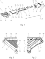
- Fig. 1 shows an exploded view of an embodiment of a lighting device 1 according to the invention.
- the lighting device is preferably for a vehicle, said lighting device 1 is configured to create a segmented light function, in particular a segmented signal light, composed of at least two segments.
- the lighting device 1 comprises a holding frame 2 with a longitudinal extension limited by a proximal end portion 2a and a distal end portion 2b opposite of the proximal end portion 2a.
- the lighting device 1 comprises a light source holder 3 having a first light source group 4a and a second light source group 4b mounted thereto, wherein each light source group 4a, 4b is configured to emit light along a, preferably common, main beam direction x1.
- the first light source group 4a and the second light source group 4b comprises two different types of light sources disposed alternating to each other on the light source holder 3.
- a first light source type is configured to emit white light
- a second light source type is configured to emit non-white, in particular amber, light.
- the lighting device 1 comprises at least two optical elements 5, 6. In the shown embodiment, three optical elements are shown. The third (and every additional) optical element is optional.
- a first optical element 5 comprises a light receiving surface 5a, a light emitting surface 5b and a lateral surface 5c, extending between the light receiving surface 5a and the light emitting surface 5b.
- the lateral surface 5c of the first optical element 5 has a longitudinal extension.
- a second optical element 6 also comprises a light receiving surface 6a, a light emitting surface 6b and a lateral surface 6c, extending between the light receiving surface 6a and the light emitting surface 6b.
- the lateral surface 6c of the second optical element 6 has a longitudinal extension.
- the light receiving surfaces 5a, 6a, the light emitting surfaces 5b, 6b and the lateral surfaces 5c, 6c of the first optical element 5 and the second optical element 6 form a transparent solid body respectively. Light received by the light receiving surfaces 5a, 6a traverses within the respective solid body towards its light emitting surface 5b, 6b via total internal reflection at the respective lateral surface 5c, 6c.
- the light source holder 3, the first optical element 5 and the second optical element 6 are configured to be mounted to the holding frame 2 in a mounting position.
- the light source holder 3 In the mounting position, the light source holder 3 is disposed at the proximal end portion 2a of the holding frame 2, such that the main beam direction x1 of the light source groups 4a, 4b is oriented along the longitudinal extension of the holding frame 2.
- the longitudinal extension of the holding frame 2 In the mounting position the longitudinal extension of the holding frame 2, the longitudinal extension of the first optical element 5 and the longitudinal extension of the second optical element 6 are essentially parallel to each other.
- the holding frame 2 at least partially, preferably fully, surrounds the lateral surface 5c of the first optical element 5 and/or the lateral surface 6c of the second optical element 6, as a shell-like structure.
- the light receiving surface 5a of the first optical element 5 and the light receiving surface 6a of the second optical element 6 are disposed at the proximal end portion 2a of the holding frame 2, such that light from the first light source group 4a is emitted towards the light receiving surface 5a of the first optical element 5 and light from the second light source group 4b is emitted towards the light receiving surface 6a of the second optical element 6, in order to form a segmented light function.
- light received via the light receiving surface 5a of the first optical element 5 traverses through the first optical element 5 and gets emitted via the light emitting surface 5b of the first optical element 5 and light received via the light receiving surface 6a of the second optical element 6 traverses through the second optical element 6 and gets emitted via the light emitting surface 6b of the second optical element 6.
- the longitudinal extension of the lateral surface 5c of the first optical element 5 and the longitudinal extension of the lateral surface 6c of the second optical element 6 extend along the main beam direction ⁇ 1 respectively.
- the light source holder 3 is disposed relative to the first optical element 5 and the second optical element 6, such that the first optical element 5 receives light exclusively from the first light source group 4a and the second optical element 6 receives light exclusively from the second light source group 4b.
- the light emitting surface 5b of the first optical element 5 and the light emitting surface 6b of the second optical element 6 are disposed at the distal end portion 2b of the holding frame 2. Furthermore, in the shown embodiment, in the mounting position the light emitting surface 5b of the first optical element 5 and the light emitting surface 6b of the second optical element 6 are disposed essentially in the same, preferably vertical, plane.
- the holding frame 2 is configured to secure the first optical element 5 and the second optical element 6 in the mounting position, such that the first optical element 5 and the second optical element 6 are secured against a movement along the main beam direction x1 beyond the mounting position and along a direction in a plane perpendicular to the main beam direction x1. Furthermore, the first optical element 5 and the second optical element 6 are spaced relative to each other by a gap, which is defined as a normal distance between the lateral surface 5c of the first optical element 5 and the lateral surface 6c of the second optical element 6.
- the first optical element 5 comprises a first protrusion 5d, extending away from the lateral surface 5c of the first optical element 5 and the second optical element 6 comprises at least one second protrusion 6d, extending away from the lateral surface 6c of the second optical element 6.
- the holding frame 2 comprises a first receiving element 2d1 and a second receiving element 2d2.
- the first receiving element 2d1 is configured to receive the first protrusion 5d of the first optical element 5
- the second receiving element 2d2 is configured to receive the second protrusion 6d of the second optical element 6.
- the first optical element 5 and the second optical element 6 are moveable (or slidable) along the main direction x and immovable along a plane perpendicular to the main beam direction x1.
- the holding frame 2 further comprises a first stopping element 2f1 configured to engage with a first contact surface 5e of the first optical element 5 and a second stopping element 2f2 configured to engage with a second contact surface 6e of the second optical element 6.
- the first stopping element 2f1 engages with the first contact surface 5e
- the second stopping element 2f2 engages with the second contact surface 6e, such that a movement of the first optical element 5 and the second optical element 6 along the main beam direction x1 beyond the mounting position is blocked.
- the lighting device 1 further comprises a cover element 7, wherein in the mounting position, the cover element 7 is mounted to the proximal end portion 2a of the holding frame 2 via mounting means 7a.
- the cover element 7 is configured to secure the first optical element 5 and the second optical element 6 against a movement along a direction opposite to the main beam direction x1.
- the cover element 7 is configured as a cooling device, in particular a cooling plate, wherein in the mounting position the light source holder 3 is disposed between the cover element 7 and the first optical element 5 and the second optical element 6.
- the cover element 7 is disposed at a light source averting backside of the light source holder 3 and is configured to cool the first light source group 4a and the second light source group 4b.
- the mounting means 7a mount the cover element 7, and preferably the light source holder 3, to the holding frame 2.
- the at least one second protrusion 6d of the second optical element 6 comprises a through hole.
- the mounting means 7a extend from the cover element 7 through said through hole and into the receiving recess at the proximal end portion 2a of the holding frame 2.
- the receiving recess is configured to engage with the mounting means 7a in order to fasten the position of the cover element 7, the second optical element 6, and preferably the light source holder 3, at the proximal end portion 2a of the holding frame 2.
- the light source holder 3 may be mounted to the cover element 7.
- the light source holder 3 comprises a, preferably flat, light source holding surface, to which the first light source group 4a and the second light source group 4b is mounted to, such that the first light source group 4a and the second light source group 4b are disposed in the same plane.
- the light source holding surface is oriented essentially orthogonal to the main beam direction x1.
- Fig. 3 shows a partial back view of the assembled lighting device 1, without the light source holder 3 and the cover element 7 mounted thereto.
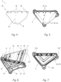
- Fig. 5 shows the lighting device 1 with the light source holder 3 mounted to the proximal end portion 2a of the frame element 2, without the cover element 7 mounted thereto.
- Fig. 2 shows a partial front view, wherein the light emitting surface 5b of the first optical element 5 and the light emitting surface 6b of the second optical element 6 is depicted.
- distance elements 2g and additional distance elements 2h are disposed at least partially between the first optical element 5 and the second optical element 6 and between the first optical element 5 and the holding frame 2 and between the second optical element 6 and the holding frame 2.
- the distance elements 2g, 2h are configured to keep the gap between the first optical element 5 and the second optical element 6 and between the first optical element 5 and the holding frame 2 and between the second optical element 6 and the holding frame 2, constant along the longitudinal extension of the first optical element 5, the longitudinal extension of the second optical element 6, and the longitudinal extension of the holding frame 2.
- the light source holder 3 comprises multiple reference elements 3a, 3b and the first optical element 5 and the second optical element 6 each comprise multiple counter reference element 5f, 6f respectively.
- Each counter reference element 5f, 6f is configured to engage with a corresponding reference element 3a, 3b of the light source holder 3, such that in the mounting position the engagement of the reference elements 3a, 3b with corresponding counter reference elements 5f, 6f secure the position of the light source holder 3 relative to the first optical element 5 and the second optical element 6 respectively.
- the holding frame 2 is formed as a hollow body comprising an inner surface 2c, said inner surface 2c faces the first optical element 5 and the second optical element 6 in the mounting position, and an outer surface 2e opposite to the inner surface 2c.
- the first receiving element 2d1 is disposed at the inner surface 2c of the hollow body and the second receiving element 2d2 is disposed at the proximal end portion 2a.
- the first receiving element 2d1 is formed as a groove along the longitudinal extension of the holding frame 2 and the second receiving element 2d2 is formed as a receiving recess formed at the proximal end portion 2a of the holding frame 2.
- the first protrusion 5d of the first optical element 5 is formed corresponding to the groove
- the second protrusion 6d of the second optical element 6 is formed corresponding to the receiving recess.
- the first stopping element 2f1 is the end portion of the groove
- the second stopping element 2f2 is the end portion of the receiving recess.
- the first contact surface 5e is formed at the first protrusion 5d of the first optical element 5 and the second contact surface 6e is formed at the second protrusion 6d of the second optical element 6.
- the first optical element 5 and the second optical element 6 are configured to be moveable relative to the holding frame 2, preferably insertable into a holding portion of the holding frame 2, along an insertion direction x2, which is essentially parallel to the main beam direction x1.
Landscapes
- Engineering & Computer Science (AREA)
- General Engineering & Computer Science (AREA)
- Physics & Mathematics (AREA)
- Microelectronics & Electronic Packaging (AREA)
- Optics & Photonics (AREA)
- Non-Portable Lighting Devices Or Systems Thereof (AREA)
- Mounting And Adjusting Of Optical Elements (AREA)
- Planar Illumination Modules (AREA)
Abstract
Description
- The invention relates to a lighting device for a vehicle, said lighting device is configured to create a segmented light function, in particular a segmented signal light, composed of at least two segments, said lighting device comprises:
- * a holding frame with a longitudinal extension limited by a proximal end portion and a distal end portion opposite of the proximal end portion,
- * a light source holder having a first light source group and a second light source group mounted thereto, wherein each light source group is configured to emit light along a, preferably common, main beam direction,
- * at least two optical elements, wherein
- a first optical element comprises a light receiving surface, a light emitting surface and a lateral surface, extending between the light receiving surface and the light emitting surface, said lateral surface of the first optical element has a longitudinal extension, wherein
- a second optical element comprises a light receiving surface, a light emitting surface and a lateral surface, extending between the light receiving surface and the light emitting surface, said lateral surface of the second optical element has a longitudinal extension,
- wherein the light source holder, the first optical element and the second optical element are configured to be mounted to the holding frame in a mounting position, in which
- the light source holder is disposed at the proximal end portion of the holding frame such that the main beam direction of the light source groups is oriented along the longitudinal extension of the holding frame,
- the light receiving surface of the first optical element and the light receiving surface of the second optical element are disposed at the proximal end portion of the holding frame, such that light from the first light source group is emitted towards the light receiving surface of the first optical element and light from the second light source group is emitted towards the light receiving surface of the second optical element, wherein light received via the light receiving surface of the first optical element traverses through the first optical element and gets emitted via the light emitting surface of the first optical element, and wherein light received via the light receiving surface of the second optical element traverses through the second optical element and gets emitted via the light emitting surface of the second optical element,
- the longitudinal extension of the lateral surface of the first optical element and the longitudinal extension of the lateral surface of the second optical element extend along the main beam direction respectively, and
- the light emitting surface of the first optical element and the light emitting surface of the second optical element are disposed at the distal end portion of the holding frame,
- wherein the holding frame is configured to secure the first optical element and the second optical element in the mounting position, such that
- the first optical element and the second optical element are secured against a movement along the main beam direction beyond the mounting position and along a direction in a plane perpendicular to the main beam direction, and such that
- the first optical element and the second optical element are spaced relative to each other by a gap, which is defined as a normal distance between the lateral surface of the first optical element and the lateral surface of the second optical element.
- The invention also relates to a vehicle lamp, in particular a vehicle turn signal lamp, a vehicle headlamp or a vehicle taillamp, comprising a lighting device.
- In the prior art lighting devices for vehicles, which are configured to create segmented light functions, in particular segmented signal lights, are well known. Usually, each segment of the segmented light function is created by a specific optical element (e.g. thick wall optics, which guide light via total internal reflexion towards a light emitting surface of the thick wall optic). In order to have a clean distinction between individual light segments, it is known to either have a relatively large gap between individual optical elements, or to dispose shielding elements or blinds between optical elements along the direction of light propagation. By installing blinds or applying large gaps, light from different optical elements can be distinguished more easily by an observer, resulting in a sharp and crisp visualization of the individual segments of the segmented light function. However, blinds and shielding elements make the entire lighting device more complex and such parts are difficult to apply and fixate in a vehicle lamp, because vehicle lamps are subject to vibrations and other mechanical forces. The alternative of having a rather large gap between individual optical elements deteriorates the optical impression of a holistic light function, which is being compiled of multiple segments.
- It is an object of the invention to provide a lighting device for a vehicle, which is capable of creating a segmented light function and at the same has an improved, simplified construction.
- To achieve this object a lighting device according to claim 1 is provided. Preferred embodiments are described in the depended claims.
- According to a first aspect of the invention, the first optical element comprises a first protrusion, extending away from the lateral surface of the first optical element, and the second optical element comprises at least one second protrusion, extending away from the lateral surface of the second optical element, wherein
- the holding frame comprises a first receiving element and a second receiving element, wherein the first receiving element is configured to receive the first protrusion of the first optical element and the second receiving element is configured to receive the second protrusion of the second optical element, wherein when the first protrusion is received by the first receiving element and the second protrusion is received by the second receiving element the first optical element and the second optical element are moveable along the main direction and immovable along a plane perpendicular to the main beam direction, wherein
- the holding frame comprises at least one first stopping element configured to engage with a first contact surface of the first optical element and at least one second stopping element configured to engage with a second contact surface of the second optical element, wherein in the mounting position, the stopping element engages with the first contact surface and the second stopping element engages with the second contact surface, such that a movement of the first optical element and the second optical element along the main beam direction beyond the mounting position is blocked,
- wherein the lighting device further comprises a cover element, wherein in the mounting position, the cover element is mounted to the proximal end portion of the holding frame via mounting means, wherein the cover element is configured to secure the first optical element and the second optical element against a movement along a direction opposite to the main beam direction.
- This has the advantage, that the first optical element and the second optical element are both secured (or fixed) along the direction of light propagation (the main beam direction), along a direction opposite to the direction of light propagation, and also along a (essentially vertical) plane, which is perpendicular to the direction of light propagation. Another advantage of the invention is, that the mounting position can be established in a convenient way, because the first optical element and the second optical element can slide along the main beam direction within the confined space defined by the frame element (which can also be described as a longitudinal hull or shell element) in order to arrive at the mounting position. The first receiving element, the second receiving element, the first stopping element, the second stopping and the cover element together advantageously provide a fixation of the first optical element and the second optical element within the frame element. Preferably, the lateral surface of the first optical element limits the first optical element in a direction orthogonal to the main beam direction, and the later surface of the second optical element limits the second optical element in a direction orthogonal to the main beam direction. The lighting device may comprise a third or more optical elements, wherein these additional optical elements may comprise protrusions equivalent to the first protrusion of the first optical element, furthermore, the frame element may comprise additional receiving elements, wherein each receiving element corresponds to a specific protrusion of a corresponding optical element. Each optical element may comprise two or more protrusions, wherein the frame element may comprise multiple receiving elements, wherein each receiving element corresponds to a specific protrusion and is configured to engage with its corresponding protrusion.
- Advantageously, the holding frame further comprises at least one, preferably multiple, distance element, wherein in the mounting position the distance element is disposed at least partially between the first optical element and the second optical element and/or between the first optical element and the holding frame and/or between the second optical element and the holding frame, wherein the at least one distance element is configured to keep the gap between the first optical element and the second optical element and/or between the first optical element and the holding frame and/or between the second optical element and the holding frame, constant along the longitudinal extension of the first optical element, the longitudinal extension of the second optical element, and/or the longitudinal extension of the holding frame. This has the advantage of providing clear and distinguishable light segments. The distance elements may be disposed at the distal end portion or the proximal end portion of the frame element.
- Advantageously, the holding frame is formed as a hollow body comprising an inner surface, said inner surface faces the first optical element and the second optical element in the mounting position, and an outer surface opposite to the inner surface, wherein the first receiving element is disposed at the inner surface of the hollow body and the second receiving element is disposed at the proximal end portion.
- Advantageously, the first contact surface is formed at the first protrusion of the first optical element and the second contact surface is formed at the second protrusion of the second optical element. Preferably the first contact surface is oriented perpendicular to the main beam direction. Preferably the second contact surface is oriented perpendicular to the main beam direction.
- Advantageously, the first receiving element is formed as a groove along the longitudinal extension of the holding frame and the second receiving element is formed as a receiving recess formed at the proximal end portion of the holding frame, wherein the first protrusion of the first optical element is formed corresponding to the groove, and the second protrusion of the second optical element is formed corresponding to the receiving recess.
- Advantageously, in the mounting position the light source holder is disposed relative to the first optical element and the second optical element, such that the first optical element receives light only from the first light source group and the second optical element receives light only from the second light source group.
- Advantageously, the light source holder comprises at least two reference elements and the first optical element and the second optical element each comprise at least one counter reference element respectively, wherein each counter reference element is configured to engage with a corresponding reference element of the light source holder, such that in the mounting position the engagement of the reference elements with corresponding counter reference elements secure the position of the light source holder relative to the first optical element and the second optical element respectively, preferably such that the first optical element receives light only from the first light source group and the second optical element receives light only from the second light source group. Advantageously, the cover element comprises additional reference elements, which are located on the cover element in specific positions, such that, in the mounting position, the additional reference elements align with the reference elements of the light source holder and the counter reference elements of the first optical element and the second optical element. Preferably, the reference elements and the additional elements are formed as through holes, and the counter reference elements are formed as spikes, wherein the shape of the spikes correspond to the shape of the through holes.
- Advantageously, the first light source group and/or the second light source group comprises two different types of light sources disposed alternating to each other on the light source holder, wherein a first light source type is configured to emit white light, wherein a second light source type is configured to emit non-white, in particular amber, light. This has the advantage of providing a larger variety in the creatable segmented light functions.
- Advantageously, the light receiving surface, the light emitting surface and the lateral surface of the first optical element and/or the second optical element form a transparent solid body respectively, wherein light received by the light receiving surface traverses within the solid body towards the light emitting surface via total internal reflection at the lateral surface.
- Advantageously, in the mounting position the holding frame at least partially, preferably fully, surrounds the lateral surface of the first optical element and/or the lateral surface of the second optical element.
- Advantageously, in the mounting position the longitudinal extension of the holding frame, the longitudinal extension of the first optical element and the longitudinal extension of the second optical element are essentially parallel to each other.
- Advantageously, the cover element is configured as a cooling device, in particular a cooling plate, wherein in the mounting position the light source holder is disposed between the cover element and the first optical element and the second optical element, wherein the cover element is disposed at a light source averting backside of the light source holder and is configured to cool the first light source group and the second light source group. Preferably, the cover element comprises of a flat portion, to which cooling fins are mounted, wherein the flat portion is oriented perpendicular to the main beam direction in the mounting position and the fins are located on the light source averting backside of the flat portion.
- Advantageously, in the mounting position the mounting means mount the cover element, and preferably the light source holder, to the holding frame, wherein the at least one second protrusion of the second optical element comprises a through hole, wherein in the mounting position the mounting means extend from the cover element through said through hole and into the receiving recess at the proximal end portion of the holding frame, wherein the receiving recess is configured to engage with the mounting means in order to fasten the position of the cover element, the second optical element, and preferably the light source holder, at the proximal end portion of the holding frame.
- Advantageously, the light source holder is mounted to the cover element, wherein the light source holder comprises a, preferably flat, light source holding surface, to which the first light source group and the second light source group is mounted to, such that the first light source group and the second light source group are disposed in the same plane, wherein in the mounting position the light source holding surface is oriented essentially orthogonal to the main beam direction.
- Advantageously, in order to establish the mounting position, the first optical element and the second optical element are configured to be moveable relative to the holding frame, preferably insertable into a holding portion of the holding frame, along an insertion direction, which is essentially parallel to the main beam direction.
- Advantageously, in the mounting position the light emitting surface of the first optical element and the light emitting surface of the second optical element are disposed essentially in the same plane.
- Advantageously, the first stopping element is disposed at a distal end portion of the first receiving element, in particular, the first stopping element may limit the longitudinal extension of the first receiving element along the main beam direction.
- Advantageously, the second stopping element is disposed at the proximal end portion of the frame element, in particular, the second stopping element may limit the longitudinal extension of the second receiving element along the main beam direction.
- According to another aspect of the invention, a vehicle lamp, in particular a vehicle turn signal lamp, a vehicle headlamp or a vehicle taillamp, is provided, comprising a lighting device according to the invention.
- Terms indicating an orientation, like "horizontal", "vertical", "left", "right", etc., are to be understood as directions, when the lighting device is mounted to a vehicle head lamp that is installed in a vehicle in its designated position.
- In the following, in order to further demonstrate the present invention, illustrative and non-restrictive embodiments are discussed, as shown in the drawings. Wherein:
- Fig. 1
- shows an exploded view of a lighting device according to an embodiment of the invention;
- Fig. 2
- shows a partial front view of the assembled lighting device of
Fig. 1 ; - Fig. 3
- shows a partial back view of the assembled lighting device of
Fig. 1 without a light source holder and a cover element; - Fig. 4
- shows a light source holder;
- Fig. 5
- shows a back view of the assembled lighting device of
Fig. 1 without a cover element; - Fig. 6
- shows another back side perspective of the assembled lighting device of
Fig. 1 without a cover element and a light source holder; - Fig. 7
- shows a frame element with a first optical element.
-
Fig. 1 shows an exploded view of an embodiment of a lighting device 1 according to the invention. The lighting device is preferably for a vehicle, said lighting device 1 is configured to create a segmented light function, in particular a segmented signal light, composed of at least two segments. - The lighting device 1 comprises a holding
frame 2 with a longitudinal extension limited by aproximal end portion 2a and adistal end portion 2b opposite of theproximal end portion 2a. The lighting device 1 comprises alight source holder 3 having a firstlight source group 4a and a secondlight source group 4b mounted thereto, wherein eachlight source group light source group 4a and the secondlight source group 4b comprises two different types of light sources disposed alternating to each other on thelight source holder 3. Preferably, a first light source type is configured to emit white light, wherein a second light source type is configured to emit non-white, in particular amber, light. - The lighting device 1 comprises at least two
optical elements - A first
optical element 5 comprises alight receiving surface 5a, alight emitting surface 5b and alateral surface 5c, extending between thelight receiving surface 5a and thelight emitting surface 5b. Thelateral surface 5c of the firstoptical element 5 has a longitudinal extension. A secondoptical element 6 also comprises a light receiving surface 6a, alight emitting surface 6b and alateral surface 6c, extending between the light receiving surface 6a and thelight emitting surface 6b. Thelateral surface 6c of the secondoptical element 6 has a longitudinal extension. In the shown embodiment, thelight receiving surfaces 5a, 6a, thelight emitting surfaces optical element 5 and the secondoptical element 6 form a transparent solid body respectively. Light received by thelight receiving surfaces 5a, 6a traverses within the respective solid body towards itslight emitting surface lateral surface - The
light source holder 3, the firstoptical element 5 and the secondoptical element 6 are configured to be mounted to the holdingframe 2 in a mounting position. In the mounting position, thelight source holder 3 is disposed at theproximal end portion 2a of the holdingframe 2, such that the main beam direction x1 of thelight source groups frame 2. In the mounting position the longitudinal extension of the holdingframe 2, the longitudinal extension of the firstoptical element 5 and the longitudinal extension of the secondoptical element 6 are essentially parallel to each other. - Essentially, in the mounting position the holding
frame 2 at least partially, preferably fully, surrounds thelateral surface 5c of the firstoptical element 5 and/or thelateral surface 6c of the secondoptical element 6, as a shell-like structure. - The
light receiving surface 5a of the firstoptical element 5 and the light receiving surface 6a of the secondoptical element 6 are disposed at theproximal end portion 2a of the holdingframe 2, such that light from the firstlight source group 4a is emitted towards thelight receiving surface 5a of the firstoptical element 5 and light from the secondlight source group 4b is emitted towards the light receiving surface 6a of the secondoptical element 6, in order to form a segmented light function. For this purpose, light received via thelight receiving surface 5a of the firstoptical element 5 traverses through the firstoptical element 5 and gets emitted via thelight emitting surface 5b of the firstoptical element 5 and light received via the light receiving surface 6a of the secondoptical element 6 traverses through the secondoptical element 6 and gets emitted via thelight emitting surface 6b of the secondoptical element 6. The longitudinal extension of thelateral surface 5c of the firstoptical element 5 and the longitudinal extension of thelateral surface 6c of the secondoptical element 6 extend along the main beam direction ×1 respectively. Furthermore, in the mounting position thelight source holder 3 is disposed relative to the firstoptical element 5 and the secondoptical element 6, such that the firstoptical element 5 receives light exclusively from the firstlight source group 4a and the secondoptical element 6 receives light exclusively from the secondlight source group 4b. - The
light emitting surface 5b of the firstoptical element 5 and thelight emitting surface 6b of the secondoptical element 6 are disposed at thedistal end portion 2b of the holdingframe 2. Furthermore, in the shown embodiment, in the mounting position thelight emitting surface 5b of the firstoptical element 5 and thelight emitting surface 6b of the secondoptical element 6 are disposed essentially in the same, preferably vertical, plane. - The holding
frame 2 is configured to secure the firstoptical element 5 and the secondoptical element 6 in the mounting position, such that the firstoptical element 5 and the secondoptical element 6 are secured against a movement along the main beam direction x1 beyond the mounting position and along a direction in a plane perpendicular to the main beam direction x1. Furthermore, the firstoptical element 5 and the secondoptical element 6 are spaced relative to each other by a gap, which is defined as a normal distance between thelateral surface 5c of the firstoptical element 5 and thelateral surface 6c of the secondoptical element 6. - In order to establish the secured connection of the first
optical element 5 and the secondoptical element 6 within the holdingframe 2, the firstoptical element 5 comprises afirst protrusion 5d, extending away from thelateral surface 5c of the firstoptical element 5 and the secondoptical element 6 comprises at least onesecond protrusion 6d, extending away from thelateral surface 6c of the secondoptical element 6. The holdingframe 2 comprises a first receiving element 2d1 and a second receiving element 2d2. The first receiving element 2d1 is configured to receive thefirst protrusion 5d of the firstoptical element 5 and the second receiving element 2d2 is configured to receive thesecond protrusion 6d of the secondoptical element 6. When thefirst protrusion 5d is received by the first receiving element 2d1 and thesecond protrusion 6d is received by the second receiving element 2d2 the firstoptical element 5 and the secondoptical element 6 are moveable (or slidable) along the main direction x and immovable along a plane perpendicular to the main beam direction x1. - The holding
frame 2 further comprises a first stopping element 2f1 configured to engage with afirst contact surface 5e of the firstoptical element 5 and a second stopping element 2f2 configured to engage with a second contact surface 6e of the secondoptical element 6. In the mounting position, the first stopping element 2f1 engages with thefirst contact surface 5e and the second stopping element 2f2 engages with the second contact surface 6e, such that a movement of the firstoptical element 5 and the secondoptical element 6 along the main beam direction x1 beyond the mounting position is blocked. - The lighting device 1 further comprises a
cover element 7, wherein in the mounting position, thecover element 7 is mounted to theproximal end portion 2a of the holdingframe 2 via mounting means 7a. Thecover element 7 is configured to secure the firstoptical element 5 and the secondoptical element 6 against a movement along a direction opposite to the main beam direction x1. - In the shown embodiment, the
cover element 7 is configured as a cooling device, in particular a cooling plate, wherein in the mounting position thelight source holder 3 is disposed between thecover element 7 and the firstoptical element 5 and the secondoptical element 6. Thecover element 7 is disposed at a light source averting backside of thelight source holder 3 and is configured to cool the firstlight source group 4a and the secondlight source group 4b. - In the mounting position the mounting means 7a mount the
cover element 7, and preferably thelight source holder 3, to the holdingframe 2. The at least onesecond protrusion 6d of the secondoptical element 6 comprises a through hole. In the mounting position the mounting means 7a extend from thecover element 7 through said through hole and into the receiving recess at theproximal end portion 2a of the holdingframe 2. The receiving recess is configured to engage with the mounting means 7a in order to fasten the position of thecover element 7, the secondoptical element 6, and preferably thelight source holder 3, at theproximal end portion 2a of the holdingframe 2. - The
light source holder 3 may be mounted to thecover element 7. Thelight source holder 3 comprises a, preferably flat, light source holding surface, to which the firstlight source group 4a and the secondlight source group 4b is mounted to, such that the firstlight source group 4a and the secondlight source group 4b are disposed in the same plane. In the mounting position the light source holding surface is oriented essentially orthogonal to the main beam direction x1. -
Fig. 3 shows a partial back view of the assembled lighting device 1, without thelight source holder 3 and thecover element 7 mounted thereto. -
Fig. 5 shows the lighting device 1 with thelight source holder 3 mounted to theproximal end portion 2a of theframe element 2, without thecover element 7 mounted thereto. -
Fig. 2 shows a partial front view, wherein thelight emitting surface 5b of the firstoptical element 5 and thelight emitting surface 6b of the secondoptical element 6 is depicted. Between the firstoptical element 5 and the secondoptical element 6 and theframe element 2 aredistance elements 2g andadditional distance elements 2h. In the mounting position thedistance elements optical element 5 and the secondoptical element 6 and between the firstoptical element 5 and the holdingframe 2 and between the secondoptical element 6 and the holdingframe 2. Thedistance elements optical element 5 and the secondoptical element 6 and between the firstoptical element 5 and the holdingframe 2 and between the secondoptical element 6 and the holdingframe 2, constant along the longitudinal extension of the firstoptical element 5, the longitudinal extension of the secondoptical element 6, and the longitudinal extension of the holdingframe 2. - As depicted in
Fig. 6 and in more detail inFig. 4 and Fig. 5 , thelight source holder 3 comprisesmultiple reference elements optical element 5 and the secondoptical element 6 each comprise multiplecounter reference element counter reference element corresponding reference element light source holder 3, such that in the mounting position the engagement of thereference elements counter reference elements light source holder 3 relative to the firstoptical element 5 and the secondoptical element 6 respectively. - As can be seen in
Fig. 7 , in the shown embodiment, the holdingframe 2 is formed as a hollow body comprising aninner surface 2c, saidinner surface 2c faces the firstoptical element 5 and the secondoptical element 6 in the mounting position, and anouter surface 2e opposite to theinner surface 2c. The first receiving element 2d1 is disposed at theinner surface 2c of the hollow body and the second receiving element 2d2 is disposed at theproximal end portion 2a. - In the shown embodiment, the first receiving element 2d1 is formed as a groove along the longitudinal extension of the holding
frame 2 and the second receiving element 2d2 is formed as a receiving recess formed at theproximal end portion 2a of the holdingframe 2. Thefirst protrusion 5d of the firstoptical element 5 is formed corresponding to the groove, and thesecond protrusion 6d of the secondoptical element 6 is formed corresponding to the receiving recess. The first stopping element 2f1 is the end portion of the groove, the second stopping element 2f2 is the end portion of the receiving recess. In the shown embodiment, thefirst contact surface 5e is formed at thefirst protrusion 5d of the firstoptical element 5 and the second contact surface 6e is formed at thesecond protrusion 6d of the secondoptical element 6. - In order to establish the mounting position, the first
optical element 5 and the secondoptical element 6 are configured to be moveable relative to the holdingframe 2, preferably insertable into a holding portion of the holdingframe 2, along an insertion direction x2, which is essentially parallel to the main beam direction x1. -
- 1
- lighting device
- 2
- holding frame
- 2a
- proximal end portion
- 2b
- distal end portion
- 2c
- inner surface
- 2d1
- first receiving element
- 2d2
- second receiving element
- 2e
- outer surface
- 2f1
- first stopping element
- 2f2
- second stopping element
- 2g, 2h
- distance elements
- 3
- light source holder
- 3a, 3b
- reference elements
- 4a
- first light source group
- 4b
- second light source group
- 5
- first optical element
- 5a
- light receiving surface
- 5b
- light emitting surface
- 5c
- lateral surface
- 5d
- first protrusion
- 5e
- first contact surface
- 5f
- counter reference element
- 6
- second optical element
- 6a
- light receiving surface
- 6b
- light emitting surface
- 6c
- lateral surface
- 6d
- second protrusion
- 6e
- second contact surface
- 6f
- counter reference element
- 7
- cover element
- 7a
- mounting means
- x1
- main beam direction
- x2
- insertion direction
Claims (15)
- Lighting device (1) for a vehicle, said lighting device (1) is configured to create a segmented light function, in particular a segmented signal light, composed of at least two segments, said lighting device (1) comprises:* a holding frame (2) with a longitudinal extension limited by a proximal end portion (2a) and a distal end portion (2b) opposite of the proximal end portion (2a),* a light source holder (3) having a first light source group (4a) and a second light source group (4b) mounted thereto, wherein each light source group (4a, 4b) is configured to emit light along a, preferably common, main beam direction (x1),* at least two optical elements (5, 6), whereina first optical element (5) comprises a light receiving surface (5a), a light emitting surface (5b) and a lateral surface (5c), extending between the light receiving surface (5a) and the light emitting surface (5b), said lateral surface (5c) of the first optical element (5) has a longitudinal extension, whereina second optical element (6) comprises a light receiving surface (6a), a light emitting surface (6b) and a lateral surface (6c), extending between the light receiving surface (6a) and the light emitting surface (6b), said lateral surface (6c) of the second optical element (6) has a longitudinal extension,wherein the light source holder (3), the first optical element (5) and the second optical element (6) are configured to be mounted to the holding frame (2) in a mounting position, in whichthe light source holder (3) is disposed at the proximal end portion (2a) of the holding frame (2) such that the main beam direction (x1) of the light source groups (4a, 4b) is oriented along the longitudinal extension of the holding frame (2),the light receiving surface (5a) of the first optical element (5) and the light receiving surface (6a) of the second optical element (6) are disposed at the proximal end portion (2a) of the holding frame (2), such that light from the first light source group (4a) is emitted towards the light receiving surface (5a) of the first optical element (5) and light from the second light source group (4b) is emitted towards the light receiving surface (6a) of the second optical element (6), wherein light received via the light receiving surface (5a) of the first optical element (5) traverses through the first optical element (5) and gets emitted via the light emitting surface (5b) of the first optical element (5), and wherein light received via the light receiving surface (6a) of the second optical element (6) traverses through the second optical element (6) and gets emitted via the light emitting surface (6b) of the second optical element (6),the longitudinal extension of the lateral surface (5c) of the first optical element (5) and the longitudinal extension of the lateral surface (6c) of the second optical element (6) extend along the main beam direction (x1) respectively, andthe light emitting surface (5b) of the first optical element (5) and the light emitting surface (6b) of the second optical element (6) are disposed at the distal end portion (2b) of the holding frame (2),wherein the holding frame (2) is configured to secure the first optical element (5) and the second optical element (6) in the mounting position, such thatthe first optical element (5) and the second optical element (6) are secured against a movement along the main beam direction (x1) beyond the mounting position and along a direction in a plane perpendicular to the main beam direction (x1), and such thatthe first optical element (5) and the second optical element (6) are spaced relative to each other by a gap, which is defined as a normal distance between the lateral surface (5c) of the first optical element (5) and the lateral surface (6c) of the second optical element (6),characterized in thatthe first optical element (5) comprises a first protrusion (5d), extending away from the lateral surface (5c) of the first optical element (5), and the second optical element (6) comprises a second protrusion (6d), extending away from the lateral surface (6c) of the second optical element (6), whereinthe holding frame (2) comprises a first receiving element (2d1) and a second receiving element (2d2), wherein the first receiving element (2d1) is configured to receive the first protrusion (5d) of the first optical element (5) and the second receiving element (2d2) is configured to receive the second protrusion (6d) of the second optical element (6), wherein when the first protrusion (5d) is received by the first receiving element (2d1) and the second protrusion (6d) is received by the second receiving element (2d2) the first optical element (5) and the second optical element (6) are moveable along the main direction (x) and immovable along a plane perpendicular to the main beam direction (x1), whereinthe holding frame (2) comprises a first stopping element (2f1) configured to engage with a first contact surface (5e) of the first optical element (5) and a second stopping element (2f2) configured to engage with a second contact surface (6e) of the second optical element (6), wherein in the mounting position, the first stopping element (2f1) engages with the first contact surface (5e) and the second stopping element (2f2) engages with the second contact surface (6e), such that a movement of the first optical element (5) and the second optical element (6) along the main beam direction (x1) beyond the mounting position is blocked,wherein the lighting device (1) further comprises a cover element (7), wherein in the mounting position, the cover element (7) is mounted to the proximal end portion (2a) of the holding frame (2) via mounting means (7a), wherein the cover element (7) is configured to secure the first optical element (5) and the second optical element (6) against a movement along a direction opposite to the main beam direction (x1).
- Lighting device (1) according to claim 1, wherein the holding frame (2) further comprises at least one, preferably multiple, distance element (2g, 2h), wherein in the mounting position the distance element (2g) is disposed at least partially between the first optical element (5) and the second optical element (6) and/or between the first optical element (5) and the holding frame (2) and/or between the second optical element (6) and the holding frame (2), wherein the at least one distance element (2g, 2h) is configured to keep the gap between the first optical element (5) and the second optical element (6) and/or between the first optical element (5) and the holding frame (2) and/or between the second optical element (6) and the holding frame (2), constant along the longitudinal extension of the first optical element (5), the longitudinal extension of the second optical element (6), and/or the longitudinal extension of the holding frame (2).
- Lighting device (1) according to any of the preceding claims, wherein the holding frame (2) is formed as a hollow body comprising an inner surface (2c), said inner surface (2c) faces the first optical element (5) and the second optical element (6) in the mounting position, and an outer surface (2e) opposite to the inner surface (2c), wherein the first receiving element (2d1) is disposed at the inner surface (2c) of the hollow body and the second receiving element (2d2) is disposed at the proximal end portion (2a).
- Lighting device (1) according to any of the preceding claims, wherein the first contact surface (5e) is formed at the first protrusion (5d) of the first optical element (5) and the second contact surface (6e) is formed at the second protrusion (6d) of the second optical element (6).
- Lighting device (1) according to any of the preceding claims, wherein the first receiving element (2d1) is formed as a groove along the longitudinal extension of the holding frame (2) and the second receiving element (2d2) is formed as a receiving recess formed at the proximal end portion (2a) of the holding frame (2), wherein the first protrusion (5d) of the first optical element (5) is formed corresponding to the groove, and the second protrusion (6d) of the second optical element (6) is formed corresponding to the receiving recess.
- Lighting device (1) according to any of the preceding claims, wherein the light source holder (3) comprises at least two reference elements (3a, 3b) and the first optical element (5) and the second optical element (6) each comprise at least one counter reference element (5f, 6f) respectively, wherein each counter reference element (5f, 6f) is configured to engage with a corresponding reference element (3a, 3b) of the light source holder (3), such that in the mounting position the engagement of the reference elements (3a, 3b) with corresponding counter reference elements (5f, 6f) secure the position of the light source holder (3) relative to the first optical element (5) and the second optical element (6) respectively, preferably such that the first optical element (5) receives light only from the first light source group (4a) and the second optical element (6) receives light only from the second light source group (4b).
- Lighting device (1) according to any of the preceding claims, wherein the first light source group (4a) and/or the second light source group (4b) comprises two different types of light sources disposed alternating to each other on the light source holder (3), wherein a first light source type is configured to emit white light, wherein a second light source type is configured to emit non-white, in particular amber, light.
- Lighting device (1) according to any of the preceding claims, wherein the light receiving surface (5a, 6a), the light emitting surface (5b, 6b) and the lateral surface (5c, 6c) of the first optical element (5) and/or the second optical element (6) form a transparent solid body respectively, wherein light received by the light receiving surface (5a, 6a) traverses within the solid body towards the light emitting surface (5b, 6b) via total internal reflection at the lateral surface (5c, 6c).
- Lighting device (1) according to any of the preceding claims, wherein in the mounting position the holding frame (2) at least partially, preferably fully, surrounds the lateral surface (5c) of the first optical element (5) and/or the lateral surface (6c) of the second optical element (6).
- Lighting device (1) according to any of the preceding claims, wherein the cover element (7) is configured as a cooling device, in particular a cooling plate, wherein in the mounting position the light source holder (3) is disposed between the cover element (7) and the first optical element (5) and the second optical element (6), wherein the cover element (7) is disposed at a light source averting backside of the light source holder (3) and is configured to cool the first light source group (4a) and the second light source group (4b).
- Lighting device (1) according to any of the preceding claims, wherein in the mounting position the mounting means (7a) mount the cover element (7), and preferably the light source holder (3), to the holding frame (2), wherein the at least one second protrusion (6d) of the second optical element (6) comprises a through hole, wherein in the mounting position the mounting means (7a) extend from the cover element (7) through said through hole and into the receiving recess at the proximal end portion (2a) of the holding frame (2), wherein the receiving recess is configured to engage with the mounting means (7a) in order to fasten the position of the cover element (7), the second optical element (6), and preferably the light source holder (3), at the proximal end portion (2a) of the holding frame (2).
- Lighting device (1) according to any of the preceding claims, wherein the light source holder (3) is mounted to the cover element (7), wherein the light source holder (3) comprises a, preferably flat, light source holding surface, to which the first light source group (4a) and the second light source group (4b) is mounted to, such that the first light source group (4a) and the second light source group (4b) are disposed in the same plane, wherein in the mounting position the light source holding surface is oriented essentially orthogonal to the main beam direction (x1).
- Lighting device (1) according to any of the preceding claims, wherein in order to establish the mounting position, the first optical element (5) and the second optical element (6) are configured to be moveable relative to the holding frame (2), preferably insertable into a holding portion of the holding frame (2), along an insertion direction (x2), which is essentially parallel to the main beam direction (x1).
- Lighting device (1) according to any of the preceding claims, wherein in the mounting position the light emitting surface (5b) of the first optical element (5) and the light emitting surface (6b) of the second optical element (6) are disposed essentially in the same plane.
- Vehicle lamp, in particular a vehicle turn signal lamp, a vehicle headlamp or a vehicle taillamp, comprising a lighting device (1) according to any of the preceding claims.
Priority Applications (5)
| Application Number | Priority Date | Filing Date | Title |
|---|---|---|---|
| EP23160752.4A EP4428434A1 (en) | 2023-03-08 | 2023-03-08 | Signaling device for a vehicle |
| JP2024028371A JP7696034B2 (en) | 2023-03-08 | 2024-02-28 | Vehicle lighting device |
| US18/597,237 US12104762B1 (en) | 2023-03-08 | 2024-03-06 | Lighting device for vehicle |
| CN202410253346.6A CN118623255A (en) | 2023-03-08 | 2024-03-06 | Vehicle lighting device and vehicle lamp including the lighting device |
| KR1020240031901A KR20240137478A (en) | 2023-03-08 | 2024-03-06 | Lighting device for a vehicle |
Applications Claiming Priority (1)
| Application Number | Priority Date | Filing Date | Title |
|---|---|---|---|
| EP23160752.4A EP4428434A1 (en) | 2023-03-08 | 2023-03-08 | Signaling device for a vehicle |
Publications (1)
| Publication Number | Publication Date |
|---|---|
| EP4428434A1 true EP4428434A1 (en) | 2024-09-11 |
Family
ID=85556299
Family Applications (1)
| Application Number | Title | Priority Date | Filing Date |
|---|---|---|---|
| EP23160752.4A Pending EP4428434A1 (en) | 2023-03-08 | 2023-03-08 | Signaling device for a vehicle |
Country Status (5)
| Country | Link |
|---|---|
| US (1) | US12104762B1 (en) |
| EP (1) | EP4428434A1 (en) |
| JP (1) | JP7696034B2 (en) |
| KR (1) | KR20240137478A (en) |
| CN (1) | CN118623255A (en) |
Cited By (1)
| Publication number | Priority date | Publication date | Assignee | Title |
|---|---|---|---|---|
| WO2026068451A1 (en) * | 2024-09-25 | 2026-04-02 | Volkswagen Aktiengesellschaft | Light module for a lighting device of a vehicle, method for operating a light module, and method for producing a light module |
Citations (8)
| Publication number | Priority date | Publication date | Assignee | Title |
|---|---|---|---|---|
| EP2372235A2 (en) * | 2010-03-27 | 2011-10-05 | Automotive Lighting Reutlingen GmbH | Vehicle light with an optical fibre lens adapter |
| WO2012132882A1 (en) * | 2011-03-30 | 2012-10-04 | 株式会社パトライト | Light-emission device |
| EP2924479A2 (en) * | 2014-03-04 | 2015-09-30 | Zizala Lichtsysteme GmbH | Light coupling protection between light functions |
| EP3453947A1 (en) * | 2017-09-12 | 2019-03-13 | PSA Automobiles SA | Vehicle optical block with light guide(s) having protuberance(s) for limiting passage of photons parasites |
| CN211600570U (en) * | 2020-02-17 | 2020-09-29 | 浙江零跑科技有限公司 | An automobile through-type LED front position lamp |
| US20200340640A1 (en) * | 2019-04-26 | 2020-10-29 | Hyundai Mobis Co., Ltd. | Lamp apparatus |
| FR3097026A1 (en) * | 2019-06-04 | 2020-12-11 | Psa Automobiles Sa | Signal light with two cantilevered light guides. |
| CN217843730U (en) * | 2022-07-27 | 2022-11-18 | 广东泰耀汽车科技有限公司 | Automobile rear combined lamp with thick-wall light guide |
Family Cites Families (7)
| Publication number | Priority date | Publication date | Assignee | Title |
|---|---|---|---|---|
| JP6818542B2 (en) * | 2016-12-26 | 2021-01-20 | スタンレー電気株式会社 | Lens holding structure and vehicle lighting equipment |
| EP3473918B1 (en) * | 2017-10-19 | 2021-12-01 | ZKW Group GmbH | Lighting device for a motor vehicle headlight |
| EP3578874A1 (en) * | 2018-06-04 | 2019-12-11 | ZKW Group GmbH | Lighting device for a motor vehicle headlamp |
| JP7291584B2 (en) * | 2019-09-17 | 2023-06-15 | 株式会社小糸製作所 | vehicle lamp |
| DE102020108943B4 (en) * | 2020-03-31 | 2022-04-28 | HELLA GmbH & Co. KGaA | Lighting device for vehicles |
| EP3907429A1 (en) * | 2020-05-04 | 2021-11-10 | ZKW Group GmbH | Lighting device for a motor vehicle |
| DE102022110747B3 (en) * | 2022-05-02 | 2023-11-02 | Motherson Innovations Company Limited | LIGHTING UNIT, VEHICLE COMPONENT AND VEHICLE |
-
2023
- 2023-03-08 EP EP23160752.4A patent/EP4428434A1/en active Pending
-
2024
- 2024-02-28 JP JP2024028371A patent/JP7696034B2/en active Active
- 2024-03-06 KR KR1020240031901A patent/KR20240137478A/en active Pending
- 2024-03-06 US US18/597,237 patent/US12104762B1/en active Active
- 2024-03-06 CN CN202410253346.6A patent/CN118623255A/en active Pending
Patent Citations (8)
| Publication number | Priority date | Publication date | Assignee | Title |
|---|---|---|---|---|
| EP2372235A2 (en) * | 2010-03-27 | 2011-10-05 | Automotive Lighting Reutlingen GmbH | Vehicle light with an optical fibre lens adapter |
| WO2012132882A1 (en) * | 2011-03-30 | 2012-10-04 | 株式会社パトライト | Light-emission device |
| EP2924479A2 (en) * | 2014-03-04 | 2015-09-30 | Zizala Lichtsysteme GmbH | Light coupling protection between light functions |
| EP3453947A1 (en) * | 2017-09-12 | 2019-03-13 | PSA Automobiles SA | Vehicle optical block with light guide(s) having protuberance(s) for limiting passage of photons parasites |
| US20200340640A1 (en) * | 2019-04-26 | 2020-10-29 | Hyundai Mobis Co., Ltd. | Lamp apparatus |
| FR3097026A1 (en) * | 2019-06-04 | 2020-12-11 | Psa Automobiles Sa | Signal light with two cantilevered light guides. |
| CN211600570U (en) * | 2020-02-17 | 2020-09-29 | 浙江零跑科技有限公司 | An automobile through-type LED front position lamp |
| CN217843730U (en) * | 2022-07-27 | 2022-11-18 | 广东泰耀汽车科技有限公司 | Automobile rear combined lamp with thick-wall light guide |
Cited By (1)
| Publication number | Priority date | Publication date | Assignee | Title |
|---|---|---|---|---|
| WO2026068451A1 (en) * | 2024-09-25 | 2026-04-02 | Volkswagen Aktiengesellschaft | Light module for a lighting device of a vehicle, method for operating a light module, and method for producing a light module |
Also Published As
| Publication number | Publication date |
|---|---|
| US20240302020A1 (en) | 2024-09-12 |
| JP2024127809A (en) | 2024-09-20 |
| CN118623255A (en) | 2024-09-10 |
| JP7696034B2 (en) | 2025-06-19 |
| KR20240137478A (en) | 2024-09-20 |
| US12104762B1 (en) | 2024-10-01 |
Similar Documents
| Publication | Publication Date | Title |
|---|---|---|
| EP2762770B1 (en) | Vehicle lighting unit | |
| US6367957B1 (en) | Lighting, especially for motor vehicles | |
| EP1920187B1 (en) | Led headlamp system | |
| CN105423209B (en) | vehicle lighting device using multi-source optical lens | |
| US20080198574A1 (en) | LED apparatus for world homologation | |
| JP5152577B2 (en) | Lighting device using ring-shaped light emitter | |
| EP4428434A1 (en) | Signaling device for a vehicle | |
| CN113958919A (en) | Optical fiber lighting device | |
| KR101968093B1 (en) | Lamp for vehicle | |
| WO1999036896A1 (en) | Lighting means having light emitting diodes | |
| US12146632B2 (en) | Exterior luminaire for a motor vehicle | |
| CN114026361A (en) | Maintaining collimator elements in lighting devices | |
| US11904760B2 (en) | Vehicle lamp including bezel having a first and second through hole | |
| US20180215310A1 (en) | Vehicular light-emitting device | |
| US20220266742A1 (en) | Vehicle lamp body device | |
| JP2017162647A (en) | Light source unit and road lighting device | |
| JP2015185216A (en) | lighting equipment | |
| KR101577999B1 (en) | LED lamp module for automobiles | |
| KR101968094B1 (en) | Lamp for vehicle | |
| CN115195579A (en) | Car light structure | |
| KR101563107B1 (en) | Led lamp for implementing seamless led illumination apparatus | |
| EP4578731A1 (en) | Lighting assembly | |
| JP6760828B2 (en) | Assembling structure of light guide rod in vehicle lighting equipment | |
| JP2019169239A (en) | Vehicular lighting fixture | |
| KR20240088338A (en) | Fastener for lamp and lamp including the same |
Legal Events
| Date | Code | Title | Description |
|---|---|---|---|
| PUAI | Public reference made under article 153(3) epc to a published international application that has entered the european phase |
Free format text: ORIGINAL CODE: 0009012 |
|
| STAA | Information on the status of an ep patent application or granted ep patent |
Free format text: STATUS: THE APPLICATION HAS BEEN PUBLISHED |
|
| AK | Designated contracting states |
Kind code of ref document: A1 Designated state(s): AL AT BE BG CH CY CZ DE DK EE ES FI FR GB GR HR HU IE IS IT LI LT LU LV MC ME MK MT NL NO PL PT RO RS SE SI SK SM TR |
|
| STAA | Information on the status of an ep patent application or granted ep patent |
Free format text: STATUS: REQUEST FOR EXAMINATION WAS MADE |
|
| 17P | Request for examination filed |
Effective date: 20250307 |
|
| RIC1 | Information provided on ipc code assigned before grant |
Ipc: F21S 43/239 20180101AFI20251216BHEP Ipc: F21S 43/243 20180101ALI20251216BHEP Ipc: F21S 43/249 20180101ALI20251216BHEP Ipc: F21S 43/27 20180101ALI20251216BHEP Ipc: F21S 43/14 20180101ALI20251216BHEP Ipc: F21S 43/19 20180101ALI20251216BHEP Ipc: F21S 43/235 20180101ALI20251216BHEP Ipc: F21S 43/20 20180101ALI20251216BHEP |
|
| GRAP | Despatch of communication of intention to grant a patent |
Free format text: ORIGINAL CODE: EPIDOSNIGR1 |
|
| STAA | Information on the status of an ep patent application or granted ep patent |
Free format text: STATUS: GRANT OF PATENT IS INTENDED |
|
| RIN1 | Information on inventor provided before grant (corrected) |
Inventor name: HUSERKA, PAVOL Inventor name: MOZNY, DAVID Inventor name: HUB, MICHAL Inventor name: FALTUS, MICHAL Inventor name: NAVRATIL, JIRI |
|
| INTG | Intention to grant announced |
Effective date: 20260129 |
|
| GRAJ | Information related to disapproval of communication of intention to grant by the applicant or resumption of examination proceedings by the epo deleted |
Free format text: ORIGINAL CODE: EPIDOSDIGR1 |
|
| STAA | Information on the status of an ep patent application or granted ep patent |
Free format text: STATUS: REQUEST FOR EXAMINATION WAS MADE |
|
| GRAP | Despatch of communication of intention to grant a patent |
Free format text: ORIGINAL CODE: EPIDOSNIGR1 |
|
| STAA | Information on the status of an ep patent application or granted ep patent |
Free format text: STATUS: GRANT OF PATENT IS INTENDED |
|
| INTC | Intention to grant announced (deleted) |