EP4428432A1 - Lamp strip connector and lamp strip - Google Patents
Lamp strip connector and lamp strip Download PDFInfo
- Publication number
- EP4428432A1 EP4428432A1 EP22891792.8A EP22891792A EP4428432A1 EP 4428432 A1 EP4428432 A1 EP 4428432A1 EP 22891792 A EP22891792 A EP 22891792A EP 4428432 A1 EP4428432 A1 EP 4428432A1
- Authority
- EP
- European Patent Office
- Prior art keywords
- light strip
- electrical connection
- base
- light
- snap
- Prior art date
- Legal status (The legal status is an assumption and is not a legal conclusion. Google has not performed a legal analysis and makes no representation as to the accuracy of the status listed.)
- Pending
Links
Images


Classifications
-
- H—ELECTRICITY
- H01—ELECTRIC ELEMENTS
- H01R—ELECTRICALLY-CONDUCTIVE CONNECTIONS; STRUCTURAL ASSOCIATIONS OF A PLURALITY OF MUTUALLY-INSULATED ELECTRICAL CONNECTING ELEMENTS; COUPLING DEVICES; CURRENT COLLECTORS
- H01R12/00—Structural associations of a plurality of mutually-insulated electrical connecting elements, specially adapted for printed circuits, e.g. printed circuit boards [PCB], flat or ribbon cables, or like generally planar structures, e.g. terminal strips, terminal blocks; Coupling devices specially adapted for printed circuits, flat or ribbon cables, or like generally planar structures; Terminals specially adapted for contact with, or insertion into, printed circuits, flat or ribbon cables, or like generally planar structures
- H01R12/70—Coupling devices
- H01R12/77—Coupling devices for flexible printed circuits, flat or ribbon cables or like structures
- H01R12/771—Details
- H01R12/772—Strain relieving means
-
- F—MECHANICAL ENGINEERING; LIGHTING; HEATING; WEAPONS; BLASTING
- F21—LIGHTING
- F21S—NON-PORTABLE LIGHTING DEVICES; SYSTEMS THEREOF; VEHICLE LIGHTING DEVICES SPECIALLY ADAPTED FOR VEHICLE EXTERIORS
- F21S4/00—Lighting devices or systems using a string or strip of light sources
- F21S4/20—Lighting devices or systems using a string or strip of light sources with light sources held by or within elongate supports
-
- F—MECHANICAL ENGINEERING; LIGHTING; HEATING; WEAPONS; BLASTING
- F21—LIGHTING
- F21S—NON-PORTABLE LIGHTING DEVICES; SYSTEMS THEREOF; VEHICLE LIGHTING DEVICES SPECIALLY ADAPTED FOR VEHICLE EXTERIORS
- F21S4/00—Lighting devices or systems using a string or strip of light sources
- F21S4/20—Lighting devices or systems using a string or strip of light sources with light sources held by or within elongate supports
- F21S4/22—Lighting devices or systems using a string or strip of light sources with light sources held by or within elongate supports flexible or deformable, e.g. into a curved shape
- F21S4/24—Lighting devices or systems using a string or strip of light sources with light sources held by or within elongate supports flexible or deformable, e.g. into a curved shape of ribbon or tape form, e.g. LED tapes
-
- F—MECHANICAL ENGINEERING; LIGHTING; HEATING; WEAPONS; BLASTING
- F21—LIGHTING
- F21V—FUNCTIONAL FEATURES OR DETAILS OF LIGHTING DEVICES OR SYSTEMS THEREOF; STRUCTURAL COMBINATIONS OF LIGHTING DEVICES WITH OTHER ARTICLES, NOT OTHERWISE PROVIDED FOR
- F21V21/00—Supporting, suspending, or attaching arrangements for lighting devices; Hand grips
- F21V21/002—Supporting, suspending, or attaching arrangements for lighting devices; Hand grips making direct electrical contact, e.g. by piercing
-
- F—MECHANICAL ENGINEERING; LIGHTING; HEATING; WEAPONS; BLASTING
- F21—LIGHTING
- F21V—FUNCTIONAL FEATURES OR DETAILS OF LIGHTING DEVICES OR SYSTEMS THEREOF; STRUCTURAL COMBINATIONS OF LIGHTING DEVICES WITH OTHER ARTICLES, NOT OTHERWISE PROVIDED FOR
- F21V21/00—Supporting, suspending, or attaching arrangements for lighting devices; Hand grips
- F21V21/005—Supporting, suspending, or attaching arrangements for lighting devices; Hand grips for several lighting devices in an end-to-end arrangement, i.e. light tracks
-
- F—MECHANICAL ENGINEERING; LIGHTING; HEATING; WEAPONS; BLASTING
- F21—LIGHTING
- F21V—FUNCTIONAL FEATURES OR DETAILS OF LIGHTING DEVICES OR SYSTEMS THEREOF; STRUCTURAL COMBINATIONS OF LIGHTING DEVICES WITH OTHER ARTICLES, NOT OTHERWISE PROVIDED FOR
- F21V23/00—Arrangement of electric circuit elements in or on lighting devices
- F21V23/06—Arrangement of electric circuit elements in or on lighting devices the elements being coupling devices, e.g. connectors
-
- F—MECHANICAL ENGINEERING; LIGHTING; HEATING; WEAPONS; BLASTING
- F21—LIGHTING
- F21Y—INDEXING SCHEME ASSOCIATED WITH SUBCLASSES F21K, F21L, F21S and F21V, RELATING TO THE FORM OR THE KIND OF THE LIGHT SOURCES OR OF THE COLOUR OF THE LIGHT EMITTED
- F21Y2103/00—Elongate light sources, e.g. fluorescent tubes
- F21Y2103/10—Elongate light sources, e.g. fluorescent tubes comprising a linear array of point-like light-generating elements
-
- F—MECHANICAL ENGINEERING; LIGHTING; HEATING; WEAPONS; BLASTING
- F21—LIGHTING
- F21Y—INDEXING SCHEME ASSOCIATED WITH SUBCLASSES F21K, F21L, F21S and F21V, RELATING TO THE FORM OR THE KIND OF THE LIGHT SOURCES OR OF THE COLOUR OF THE LIGHT EMITTED
- F21Y2115/00—Light-generating elements of semiconductor light sources
- F21Y2115/10—Light-emitting diodes [LED]
-
- H—ELECTRICITY
- H01—ELECTRIC ELEMENTS
- H01R—ELECTRICALLY-CONDUCTIVE CONNECTIONS; STRUCTURAL ASSOCIATIONS OF A PLURALITY OF MUTUALLY-INSULATED ELECTRICAL CONNECTING ELEMENTS; COUPLING DEVICES; CURRENT COLLECTORS
- H01R12/00—Structural associations of a plurality of mutually-insulated electrical connecting elements, specially adapted for printed circuits, e.g. printed circuit boards [PCB], flat or ribbon cables, or like generally planar structures, e.g. terminal strips, terminal blocks; Coupling devices specially adapted for printed circuits, flat or ribbon cables, or like generally planar structures; Terminals specially adapted for contact with, or insertion into, printed circuits, flat or ribbon cables, or like generally planar structures
- H01R12/70—Coupling devices
- H01R12/7005—Guiding, mounting, polarizing or locking means; Extractors
- H01R12/7011—Locking or fixing a connector to a PCB
- H01R12/7017—Snap means
- H01R12/7023—Snap means integral with the coupling device
-
- H—ELECTRICITY
- H01—ELECTRIC ELEMENTS
- H01R—ELECTRICALLY-CONDUCTIVE CONNECTIONS; STRUCTURAL ASSOCIATIONS OF A PLURALITY OF MUTUALLY-INSULATED ELECTRICAL CONNECTING ELEMENTS; COUPLING DEVICES; CURRENT COLLECTORS
- H01R13/00—Details of coupling devices of the kinds covered by groups H01R12/70 or H01R24/00 - H01R33/00
- H01R13/02—Contact members
- H01R13/22—Contacts for co-operating by abutting
- H01R13/24—Contacts for co-operating by abutting resilient; resiliently-mounted
- H01R13/2442—Contacts for co-operating by abutting resilient; resiliently-mounted with a single cantilevered beam
-
- H—ELECTRICITY
- H01—ELECTRIC ELEMENTS
- H01R—ELECTRICALLY-CONDUCTIVE CONNECTIONS; STRUCTURAL ASSOCIATIONS OF A PLURALITY OF MUTUALLY-INSULATED ELECTRICAL CONNECTING ELEMENTS; COUPLING DEVICES; CURRENT COLLECTORS
- H01R13/00—Details of coupling devices of the kinds covered by groups H01R12/70 or H01R24/00 - H01R33/00
- H01R13/58—Means for relieving strain on wire connection, e.g. cord grip, for avoiding loosening of connections between wires and terminals within a coupling device terminating a cable
- H01R13/5833—Means for relieving strain on wire connection, e.g. cord grip, for avoiding loosening of connections between wires and terminals within a coupling device terminating a cable the cable being forced in a tortuous or curved path, e.g. knots in cable
Definitions
- the present application relates to the technical field of light strips, and in particular to a light strip connector and a light strip.
- Low-voltage light strips can be cut infinitely, and currently, there are the following two ways for the cut light strips to achieve electrical conduction: one is welding, and the disadvantage of welding is that it requires a soldering iron during construction and the operation is very troublesome; the other is to use a light strip connector, which can quickly achieve electrical conduction and facilitate installation.
- the following problems are common in the market for strip connectors: first, the elasticity of the spring sheet is poor; due to the requirement of the number of times of plug connection, it is hoped that the spring sheet can have good elasticity; on the other hand, the light strips are available with adhesive and non-adhesive backing, and the thickness of the adhesive backing varies greatly, so the elasticity of the spring sheet is required, and it is hoped that the spring sheet can be compatible with light strips of different thicknesses; secondly, the light strip cannot prevent pulling and dragging, and the light strip is easy to detach from the light strip connector, thus affecting the reliability of the electrical contact of the light strip; or, the light strip can prevent pulling and dragging but cannot satisfy the situation where the lamp beads are arranged densely. Therefore, how to improve the reliability of the light strip connector has become an urgent problem that needs to be solved.
- the object of the present application is to provide a light strip connector and a light strip to solve the problem that the elasticity of the spring sheet is poor, the light strip cannot prevent pulling and dragging, or can prevent pulling and dragging but cannot satisfy the situation where the lamp beads are arranged densely, so as to improve the reliability of the operation of the light strip connector.
- an end of the fixing portion away from the electrical connection structure is provided with a first convex portion extending in a direction close to the cover closure portion, and a side of the cover closure portion close to the base is provided with a matching portion that matches the first convex portion;
- the matching portion comprises a groove and a second convex portion at both ends of the groove and extending in a direction away from the cover closure portion, a projection of the first convex portion on the cover closure portion is in the groove, and a plane where a highest point of the first convex portion is located is higher than a plane where a lowest point of the second convex portion is located.
- the fixing portion comprises a support portion fixedly connected below the conductive terminal and a connection portion below the support portion; a side wall of the support portion close to the base is provided with a first snap portion, the base is provided with a second snap portion at a position corresponding to the first snap portion, and the support portion is snap-connected to the base through snap-fitting of the first snap portion and the second snap portion.
- connection portion comprises a first connection portion at both ends of the connection portion and a second connection portion connected to the first connection portion, and a side of the fixing groove away from a side wall of the base is provided with a blocking portion matching the first connection portion to limit a connection to the first connection portion.
- the conductive terminal comprises a base portion and an elastic portion formed by bending an end of the base portion toward a side close to the base, a first electrical connection portion is provided on the elastic portion, the light strip body is provided with a second electrical connection portion at a position corresponding to the first electrical connection portion, and the conductive terminal is electrically connected to the light strip body under a cooperation of the first electrical connection portion and the second electrical connection portion.
- a plane where a lowest point of the elastic portion is located is lower than a plane where a highest point of the first convex portion is located.
- the base further comprises a partition in the receiving space, a gap is provided between the partition and a side wall of the base, and the electrical connection structure is at least partially received in the fixing groove after the electrical connection structure passes through the gap.
- the two electrical connection structures are arranged in parallel in the receiving space, and an extension direction of the electrical connection structures is identical to an extension direction of the light strip body.
- the present application further discloses a light strip
- the light strip comprises a light strip body and the above light strip connector, an end of the light strip body provided with a second electrical connection portion abuts against a partition of the light strip connector, and the second electrical connection portion is electrically connected to a first electrical connection portion of the light strip connector under a snap connection between the cover closure portion and the base of the light strip connector; and the light strip body comprises a substrate and a light-emitting component electrically connected to the substrate, and two electrical connection structures of the light strip connector are respectively on both sides of the light-emitting component.
- the beneficial effects of the present application are as follows.
- the present application solves the problem that the light strip cannot prevent pulling and dragging through the cooperating extrusion on the light strip body by the matching portion and the first convex portion, and improves the performance of the light strip for preventing pulling and dragging.
- the light strip body is electrically connected to the conductive terminal under the elastic resistance of the elastic portion, thus achieving high reliability.
- the sufficient deformation of the elastic portion itself can effectively improve the compatibility with light strips of different thicknesses.
- the conductive terminals on both sides of the light-emitting component, the situation where the light-emitting components are arranged very densely can be well satisfied.
- a light strip connector 100 provided by the present application is used for connecting adjacent light strips 200 and/or connecting the light strip 200 and a power cord, and the light strip 200 includes a light strip body 5.
- the light strip connector 100 includes a cover closure portion 1, a base 2 and at least one electrical connection structure 4.
- a receiving space 3 is formed between the cover closure portion 1 and the base 2, and the electrical connection structure 4 is in the receiving space 3.
- the end of the receiving space 3 has an open structure, so that the light strip body 5 can abut against a partition 22 in the receiving space 3.
- the electrical connection structure 4 includes a conductive terminal 41 electrically connected to the lamp strip body 5, and a fixing portion 42 fixedly connected to the conductive terminal 41.
- a fixing groove 25 is provided on the base 2, and the fixing portion 42 is at least partially received in the fixing groove 25, and an accommodating space 6 for accommodating the lamp strip body 5 is provided between the conductive terminal 41 and the fixing portion 42.
- a rotating structure is formed between the cover closure portion 1 and the base 2, and the rotation range of the rotating structure is 0° ⁇ 180°.
- the cover closure portion 1 and the base 2 can be opened or closed through the rotating structure, so that the light strip 200 can be easily placed, which facilitate operation.
- the rotating structure is a thin plate, preferably, the thin plate is a plastic thin plate.
- the rotating structure may be a rotating shaft or other components capable of realizing the rotating function, and may be specifically set according to actual usage requirements, which is not further limited in the present application.
- the cover closure portion 1 and the base 2 are made of plastic to enhance the plasticity of the product.
- the cover closure portion 1, the thin plate and the base 2 are an integral injection molding structure, which is beneficial to mass production by producers and high production efficiency. Moreover, it is also convenient for users to use.
- the cover closure portion 1 and the base 2 are rotationally connected through the plastic thin plate, which can effectively make the cover closure portion 1 rotate around the base 2 to facilitate disassembly and/or fastening, snap-fit operations.
- the cover closure portion 1, the thin plate and the base 2 may also adopt a split joint connection structure.
- the cover closure portion 1 includes a first snap portion 11 and an opening 12.
- the first snap portion 11 is used to cooperate with a second snap portion 24 of the base 2 to realize the snap-closure of the cover closure portion 1 on the base 2.
- the cover closure portion 1 is provided with two symmetrically arranged first snap portions 11.
- the number of openings 12 is two, and the openings 12 are located on the sides of the first snap portions 11 close to the rotating structure.
- the width of the opening 12 is slightly larger than the width of a light-emitting component 512 on the lamp strip body 5, in this way, the interference of a matching portion 13 on the light-emitting component 512 can be effectively reduced, so as to adapt to the dense arrangement of the light-emitting components 512 and satisfy the user's experience.
- a side of the cover closure portion 1 close to the base 2 is provided with the matching portion 13 that matches a first convex portion 4222, in other words, the matching portion 13 is formed at the opening 12 of the cover closure portion 1 and extends toward the direction of the receiving space 3.
- the matching portion 13 is used to perform cooperating extrusion on the light strip body 5 with the first convex portion 4222 to achieve anti-pulling fixation of the light strip body 5.
- the matching portion 13 includes a groove 132 and a second convex portion 131 at both ends of the groove and extending in a direction away from the cover closure portion 1.
- the projection of the first convex portion 4222 on the cover closure portion 1 is in the groove 132, and the plane where the highest point of the first convex portion 4222 is located is higher than the plane where the lowest point of the second convex portion 131 is located.
- the light strip body 5 can be extruded into an "S" shape and received into the accommodating space 6, thereby achieving anti-pulling fixation of the light strip body 5.
- the light strip body 5 is deformed under the cooperating extrusion of the matching portion 13 and the first convex portion 4222 to be limited in the groove 132.
- the number of the second convex portions 131 is two, and the groove 132 is formed between the two second convex portions 131.
- the two second convex portions 131 are both tooth-like structures, and outer side walls of the two second convex portions 131 are both inwardly concave structures, so as to be accommodated in the receiving space 3 and improve the overall consistency of the light strip 200. Moreover, it can also save materials, reduce production costs, and improve economic benefits.
- the two second convex portions 131 both face the same direction. In other embodiments, the structures of the two second convex portions 131 may not be exactly the same, which is not limited by the present application.
- the base 2 is provided with an auxiliary portion 21 and a partition 22 at a position corresponding to a support portion 421, the partition 22 is in the receiving space 3.
- a gap 23 is provided between the partition 22 and a side wall of the base 2, and the electrical connection structure 4 is at least partially received in the fixing groove 25 after the electrical connection structure 4 passes through the gap 23. That is, it needs to be ensured that the first convex portion 4222 of the electrical connection structure 4 is exposed in the receiving space 3.
- the partition 22 is between two auxiliary portions 21, and gaps 23 are respectively formed between both sides of the partition 22 and the two auxiliary portions 21, and the fixing portion 42 passes through the gap 23 and is fixedly connected to the base 2.
- the upper surface of the partition 22 is provided with a step portion 221 to support the conductive terminal 41.
- the partition 22 is a blind hole structure, and the side wall of the partition 22 can abut against the light strip body 5, thereby saving materials and reducing production costs.
- the partition 22 may also be a solid structure, which can be determined specifically according to actual requirements, the present application is not limited here.
- the auxiliary portion 21, the partition 22 and the base 2 may also be an integral extrusion molding structure.
- the number of the auxiliary portions 21 is two, and the two auxiliary portions 21 are symmetrically arranged on the inner wall, on the long side, of the base 2.
- the base 2 is provided with a second snap portion 24 at a position corresponding to the first snap portion 11, and the second snap portion 24 matches the first snap portion 11 to realize the snap-closure of the cover closure portion 1.
- the first snap portion 11 is a protrusion block
- the second snap portion 24 is a snap groove.
- the first snap portion 11 is a snap groove
- the second snap portion 24 is a protrusion block.
- the structures of the first snap portion 11 and the second snap portion 24 in the present application are only exemplary and should not be limited thereto, as long as the cover closure portion 1 can be closed on the base 2.
- the conductive terminal 41 includes a base portion 411 and an elastic portion 412 formed by bending an end of the base portion 411 toward a side close to the base 2, and the elastic portion 412 is provided with a first electrical connection portion 413.
- the lowest point of the elastic portion 412 is provided with the first electrical connection portion 413
- the light strip body 5 is provided with a second electrical connection portion 511 at a position corresponding to the first electrical connection portion 413.
- the cover closure portion 1 will press the conductive terminal 41 when the cover closure portion 1 is closed, and the conductive terminal 41 is electrically connected to the light strip body 5 under the cooperation of the first electrical connection portion 413 and the second electrical connection portion 511.
- the second electrical connection portion 511 is electrically connected to the first electrical connection portion 413 under the elastic resistance of the elastic portion 412. In this way, with the sufficient deformation of the elastic portion 412 itself, the reliability of the electrical contact between the light strip body 5 and the conductive terminal 41 can be effectively improved.
- the elastic portion 412 and the first convex portion 4222 are provided on the same electrical connection structure 4, thus improving the installation efficiency.
- the elastic portion 412 and the first convex portion 4222 may also be provided separately.
- the fixing portion 42 includes a support portion 421 fixedly connected below the conductive terminal 41 and a connection portion 422 below the support portion 421, a side wall of the support portion 421 close to the base 2 is provided with a first snap portion 4211, the base 2 is provided with a second snap portion 211 at a position corresponding to the first snap portion 4211, and the support portion 421 is snap-connected to the base 2 through the snap-fitting of the first snap portion 4211 and the second snap portion 211.
- the first snap portion 4211 is a barb
- the second snap portion 211 is a limiting groove.
- the barb is on a side of the support portion 421 close to the auxiliary portion 21, and the connection point between the barb and the support portion 421 is below the end of the barb.
- a blocking wall 212 is provided above the limiting groove.
- the end of the fixing portion 42 away from the electrical connection structure 4 is provided with a first convex portion 4222 extending in a direction close to the cover closure portion 1.
- the plane where the lowest point of the elastic portion 412 is located is lower than the plane where the highest point of the first convex portion 4222 is located.
- connection portion 422 is at least partially in the fixing groove 25, an end of the connection portion 422 facing the fixing groove 25 is provided with a clamping portion 4221, and the connection portion 422 is fixedly connected to the fixing groove 25 through the clamping portion 4221.
- the clamping portion 4221 is connected to the fixing groove 25 in an interference fit manner to improve the stability of the connection between the fixing portion 42 and the base 2.
- the fixing groove 25 may be provided with a give way portion, and the connection portion 422 is fixedly connected to the base 2 through the limitation of the clamping portion 4221 in the give way portion.
- the clamping portion 4221 is an upwardly inclined spike.
- the shape and number of the clamping portion 4221 may be determined according to specific needs, and are not further limited in the present application.
- connection portion 422 includes a first connection portion 422a at both ends of the connection portion 422 and a second connection portion 422b connected to the first connection portion 422a, and the clamping portion 4221 and the first convex portion 4222 are both on the first connection portion 422a.
- a blocking portion 251 matching the first connection portion 422a is provided on the side of the fixing groove 25 away from the side wall of the base 2 to limit the first connection portion 422a, so as to avoid a situation in which the electrical contact between the light strip body 5 and the conductive terminal 41 is poor due to a serious tilt of the first connection portion 422a.
- the second connection portion 422b includes a bent portion 4223, and the bent portion 4223 is formed by bending the second connection portion 422b toward the side close to the blocking portion 251 to further improve the fixing stability of the conductive terminal 41.
- the first connection portion 422a and the second connection portion 422b is an integrally formed structure.
- the two electrical connection structures 4 are arranged in parallel in the receiving space 3, and the extension direction of the electrical connection structures 4 is identical to the extension direction of the light strip body 5.
- the present application further discloses a light strip 200.
- the light strip 200 includes a light strip body 5 and the aforementioned light strip connector 100, and the light strip body 5 is in the receiving space 3 of the light strip connector 100.
- An end of the light strip body 5 provided with the second electrical connection portion 511 abuts against the partition 22 of the light strip connector 100, and the second electrical connection portion 511 is electrically connected to the first electrical connection portion 413 of the light strip connector 100 under the snap connection between the cover closure portion 1 and the base 2 of the light strip connector 100.
- the light strip 200 adopting the light strip connector 100 has a better anti-pulling effect, and improves the stability and reliability of the electrical contact between the light strip body 5 and the conductive terminal 41.
- the light strip body 5 includes a substrate 51 and a light-emitting component 512 electrically connected to the substrate 51.
- two electrical connection structures 4 of the light strip connector 100 are respectively on both sides of the light-emitting component 512.
- the lamp beads are arranged more densely, which can reduce the graininess sense and improve the user's experience.
- the light-emitting component 512 is a lamp bead.
- the light strip body 5 in the present application adopts a flexible printed circuit (FPC), which can save more space.
- the FPC is connected through the light strip connector 100, which has light weight, high reliability and low cost.
- two light strip connectors 100 may be used on the light strip 200. It may be known that the light strip connector 100 is an independent structure, so the light strip connector 100 can be applied for splicing between two adjacent light strip bodies 5, or for electrically connecting the light strip body 5 to an external power supply. Specifically, both sides of the partition 22 of a light strip connector 100 respectively abut against a light strip body 5, thereby realizing the splicing of two adjacent light strip bodies 5. For the other light strip connector 100', both sides of the partition 22' of the light strip connector 100' respectively abut against the light strip body 5 and the external power cord.
- One end of the conductive terminal 41' away from the light strip body 5 is electrically connected to an external power supply through the external power cord to provide power to the light strip body 5.
- the specific structures of the light strip connector 100' and the light strip connector 100 may not be exactly the same, as long as they can achieve electrical connection with the external power cord.
- the present application solves the problem that the light strip 200 cannot prevent pulling and dragging through the cooperating extrusion on the light strip body 5 by the matching portion 13 and the first convex portion 4222, and improves the performance of the light strip 200 for preventing pulling and dragging.
- the conductive terminal 41 with the elastic portion 412, the light strip body 5 is electrically connected to the conductive terminal 41 under the elastic resistance of the elastic portion 412, thus achieving high reliability.
- the sufficient deformation of the elastic portion 412 itself can effectively improve the compatibility with light strips 200 of different thicknesses.
- the conductive terminals 41 on both sides of the light-emitting component 512, the situation where the light-emitting components 512 are arranged very densely can be well satisfied.
Landscapes
- Engineering & Computer Science (AREA)
- General Engineering & Computer Science (AREA)
- Fastening Of Light Sources Or Lamp Holders (AREA)
- Arrangement Of Elements, Cooling, Sealing, Or The Like Of Lighting Devices (AREA)
- Coupling Device And Connection With Printed Circuit (AREA)
Abstract
Description
- The present application claims the priority to
Chinese patent application No. 202122754711.6, filed on November 11, 2021 - The present application relates to the technical field of light strips, and in particular to a light strip connector and a light strip.
- At present, light strips are used more and more widely, especially low-voltage light strips. Low-voltage light strips can be cut infinitely, and currently, there are the following two ways for the cut light strips to achieve electrical conduction: one is welding, and the disadvantage of welding is that it requires a soldering iron during construction and the operation is very troublesome; the other is to use a light strip connector, which can quickly achieve electrical conduction and facilitate installation. However, the following problems are common in the market for strip connectors: first, the elasticity of the spring sheet is poor; due to the requirement of the number of times of plug connection, it is hoped that the spring sheet can have good elasticity; on the other hand, the light strips are available with adhesive and non-adhesive backing, and the thickness of the adhesive backing varies greatly, so the elasticity of the spring sheet is required, and it is hoped that the spring sheet can be compatible with light strips of different thicknesses; secondly, the light strip cannot prevent pulling and dragging, and the light strip is easy to detach from the light strip connector, thus affecting the reliability of the electrical contact of the light strip; or, the light strip can prevent pulling and dragging but cannot satisfy the situation where the lamp beads are arranged densely. Therefore, how to improve the reliability of the light strip connector has become an urgent problem that needs to be solved.
- In view of this, it is indeed necessary to provide a light strip connector and a light strip to solve the above-mentioned problems.
- The object of the present application is to provide a light strip connector and a light strip to solve the problem that the elasticity of the spring sheet is poor, the light strip cannot prevent pulling and dragging, or can prevent pulling and dragging but cannot satisfy the situation where the lamp beads are arranged densely, so as to improve the reliability of the operation of the light strip connector.
- In order to realize the above object, the present application provides a light strip connector, for connecting adjacent light strips and/or connecting a light strip and a power cord, the light strip comprises a light strip body, and the light strip connector comprises a cover closure portion, a base and at least one electrical connection structure; a receiving space is formed between the cover closure portion and the base, the electrical connection structure is in the receiving space, and the electrical connection structure comprises a conductive terminal electrically connected to the light strip body, and a fixing portion fixedly connected to the conductive terminal; a fixing groove is provided on the base, the fixing portion is at least partially received in the fixing groove, and an accommodating space for accommodating the light strip body is provided between the conductive terminal and the fixing portion.
- As a further improvement of the present application, an end of the fixing portion away from the electrical connection structure is provided with a first convex portion extending in a direction close to the cover closure portion, and a side of the cover closure portion close to the base is provided with a matching portion that matches the first convex portion; the matching portion comprises a groove and a second convex portion at both ends of the groove and extending in a direction away from the cover closure portion, a projection of the first convex portion on the cover closure portion is in the groove, and a plane where a highest point of the first convex portion is located is higher than a plane where a lowest point of the second convex portion is located.
- As a further improvement of the present application, the fixing portion comprises a support portion fixedly connected below the conductive terminal and a connection portion below the support portion; a side wall of the support portion close to the base is provided with a first snap portion, the base is provided with a second snap portion at a position corresponding to the first snap portion, and the support portion is snap-connected to the base through snap-fitting of the first snap portion and the second snap portion.
- As a further improvement of the present application, the connection portion is at least partially in the fixing groove, an end of the connection portion facing the fixing groove is provided with a clamping portion, and the connection portion is fixedly connected to the fixing groove through the clamping portion.
- As a further improvement of the present application, the connection portion comprises a first connection portion at both ends of the connection portion and a second connection portion connected to the first connection portion, and a side of the fixing groove away from a side wall of the base is provided with a blocking portion matching the first connection portion to limit a connection to the first connection portion.
- As a further improvement of the present application, the conductive terminal comprises a base portion and an elastic portion formed by bending an end of the base portion toward a side close to the base, a first electrical connection portion is provided on the elastic portion, the light strip body is provided with a second electrical connection portion at a position corresponding to the first electrical connection portion, and the conductive terminal is electrically connected to the light strip body under a cooperation of the first electrical connection portion and the second electrical connection portion.
- As a further improvement of the present application, in a direction perpendicular to the light strip body, a plane where a lowest point of the elastic portion is located is lower than a plane where a highest point of the first convex portion is located.
- As a further improvement of the present application, the base further comprises a partition in the receiving space, a gap is provided between the partition and a side wall of the base, and the electrical connection structure is at least partially received in the fixing groove after the electrical connection structure passes through the gap.
- As a further improvement of the present application, there are two electrical connection structures, the two electrical connection structures are arranged in parallel in the receiving space, and an extension direction of the electrical connection structures is identical to an extension direction of the light strip body.
- To further realize the above object, the present application further discloses a light strip, the light strip comprises a light strip body and the above light strip connector, an end of the light strip body provided with a second electrical connection portion abuts against a partition of the light strip connector, and the second electrical connection portion is electrically connected to a first electrical connection portion of the light strip connector under a snap connection between the cover closure portion and the base of the light strip connector; and the light strip body comprises a substrate and a light-emitting component electrically connected to the substrate, and two electrical connection structures of the light strip connector are respectively on both sides of the light-emitting component.
- The beneficial effects of the present application are as follows. The present application solves the problem that the light strip cannot prevent pulling and dragging through the cooperating extrusion on the light strip body by the matching portion and the first convex portion, and improves the performance of the light strip for preventing pulling and dragging. Secondly, by providing a conductive terminal with an elastic portion, the light strip body is electrically connected to the conductive terminal under the elastic resistance of the elastic portion, thus achieving high reliability. Moreover, the sufficient deformation of the elastic portion itself can effectively improve the compatibility with light strips of different thicknesses. Furthermore, by arranging the conductive terminals on both sides of the light-emitting component, the situation where the light-emitting components are arranged very densely can be well satisfied.
- The technical solutions and other beneficial effects of the present application will be apparent through a detailed description of the specific embodiments of the present application in conjunction with the drawings.
-
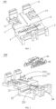
FIG. 1 is a structural schematic diagram of a light strip connector according to a preferred embodiment of the present application; -
FIG. 2 is an exploded view ofFIG. 1 ; -
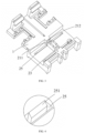
FIG. 3 is a structural schematic diagram of a cover closure portion and a base; -
FIG. 4 is an enlarged view of a structure of the circled part inFIG. 3 ; -
FIG. 5 is a structural schematic diagram of an electrical connection structure; -
FIG. 6 is a front view ofFIG. 5 ; -
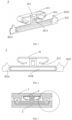
FIG. 7 is a cross-sectional view of a light strip connector; -
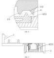
FIG. 8 is an enlarged view of a structure of the circled part inFIG. 7 ; -
FIG. 9 is a partial cross-sectional view of a light strip connector; -
FIG. 10 is a structural schematic diagram of a light strip according to a preferred embodiment of the present application; -
FIG. 11 is a structural schematic diagram of a substrate of a light strip; -
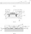
FIG. 12 is a first cross-sectional view of a light strip; -
FIG. 13 is a second cross-sectional view of a light strip; -
FIG. 14 is a structural schematic diagram of a light strip in a first state; -
FIG. 15 is a structural schematic diagram of a light strip in a second state; -
FIG. 16 is a top view ofFIG. 15 ; and -
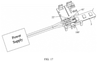
FIG. 17 is a structural schematic diagram of a connection between a light strip connector, a light strip body and an external power supply in the present application. - In order to make objects, technical solutions and advantages of the present application apparent, the present application will be described in detail below with reference to the drawings and specific embodiments.
- Here, it should be noted that, in order to avoid blurring the present application with unnecessary details, only the structures and/or processing steps closely related to the solutions of the present application are illustrated in the drawings, and other details that are not closely related to the present application are omitted.
- Furthermore, it should be noted that the terms "comprise," "comprising," "include," "including," etc., or any other variant thereof are intended to cover non-exclusive inclusion, such that a process, method, article or device including a set of elements includes not only those elements, but also other elements not expressly listed, or other elements that are inherent to such process, method, article or device.
- Please refer to
FIG. 1 to FIG. 9 and in conjunction withFIG. 10 to FIG. 17 , alight strip connector 100 provided by the present application is used for connectingadjacent light strips 200 and/or connecting thelight strip 200 and a power cord, and thelight strip 200 includes alight strip body 5. Thelight strip connector 100 includes acover closure portion 1, abase 2 and at least oneelectrical connection structure 4. Areceiving space 3 is formed between thecover closure portion 1 and thebase 2, and theelectrical connection structure 4 is in thereceiving space 3. The end of thereceiving space 3 has an open structure, so that thelight strip body 5 can abut against apartition 22 in thereceiving space 3. Theelectrical connection structure 4 includes aconductive terminal 41 electrically connected to thelamp strip body 5, and afixing portion 42 fixedly connected to theconductive terminal 41. Afixing groove 25 is provided on thebase 2, and thefixing portion 42 is at least partially received in thefixing groove 25, and anaccommodating space 6 for accommodating thelamp strip body 5 is provided between theconductive terminal 41 and thefixing portion 42. - A rotating structure is formed between the
cover closure portion 1 and thebase 2, and the rotation range of the rotating structure is 0°~180°. Thecover closure portion 1 and thebase 2 can be opened or closed through the rotating structure, so that thelight strip 200 can be easily placed, which facilitate operation. In a preferred embodiment, the rotating structure is a thin plate, preferably, the thin plate is a plastic thin plate. In other embodiments, the rotating structure may be a rotating shaft or other components capable of realizing the rotating function, and may be specifically set according to actual usage requirements, which is not further limited in the present application. Preferably, thecover closure portion 1 and thebase 2 are made of plastic to enhance the plasticity of the product. Preferably, thecover closure portion 1, the thin plate and thebase 2 are an integral injection molding structure, which is beneficial to mass production by producers and high production efficiency. Moreover, it is also convenient for users to use. Thecover closure portion 1 and thebase 2 are rotationally connected through the plastic thin plate, which can effectively make thecover closure portion 1 rotate around thebase 2 to facilitate disassembly and/or fastening, snap-fit operations. In other embodiments, thecover closure portion 1, the thin plate and thebase 2 may also adopt a split joint connection structure. - The
cover closure portion 1 includes afirst snap portion 11 and anopening 12. Thefirst snap portion 11 is used to cooperate with asecond snap portion 24 of thebase 2 to realize the snap-closure of thecover closure portion 1 on thebase 2. Preferably, thecover closure portion 1 is provided with two symmetrically arrangedfirst snap portions 11. The number ofopenings 12 is two, and theopenings 12 are located on the sides of thefirst snap portions 11 close to the rotating structure. In a preferred embodiment, the width of theopening 12 is slightly larger than the width of a light-emittingcomponent 512 on thelamp strip body 5, in this way, the interference of a matchingportion 13 on the light-emittingcomponent 512 can be effectively reduced, so as to adapt to the dense arrangement of the light-emittingcomponents 512 and satisfy the user's experience. - A side of the
cover closure portion 1 close to thebase 2 is provided with the matchingportion 13 that matches a firstconvex portion 4222, in other words, the matchingportion 13 is formed at theopening 12 of thecover closure portion 1 and extends toward the direction of the receivingspace 3. The matchingportion 13 is used to perform cooperating extrusion on thelight strip body 5 with the firstconvex portion 4222 to achieve anti-pulling fixation of thelight strip body 5. - Specifically, the matching
portion 13 includes agroove 132 and a secondconvex portion 131 at both ends of the groove and extending in a direction away from thecover closure portion 1. The projection of the firstconvex portion 4222 on thecover closure portion 1 is in thegroove 132, and the plane where the highest point of the firstconvex portion 4222 is located is higher than the plane where the lowest point of the secondconvex portion 131 is located. In this way, thelight strip body 5 can be extruded into an "S" shape and received into theaccommodating space 6, thereby achieving anti-pulling fixation of thelight strip body 5. In other words, thelight strip body 5 is deformed under the cooperating extrusion of the matchingportion 13 and the firstconvex portion 4222 to be limited in thegroove 132. In a preferred embodiment, the number of the secondconvex portions 131 is two, and thegroove 132 is formed between the two secondconvex portions 131. Preferably, the two secondconvex portions 131 are both tooth-like structures, and outer side walls of the two secondconvex portions 131 are both inwardly concave structures, so as to be accommodated in the receivingspace 3 and improve the overall consistency of thelight strip 200. Moreover, it can also save materials, reduce production costs, and improve economic benefits. Preferably, the two secondconvex portions 131 both face the same direction. In other embodiments, the structures of the two secondconvex portions 131 may not be exactly the same, which is not limited by the present application. - The
base 2 is provided with anauxiliary portion 21 and apartition 22 at a position corresponding to asupport portion 421, thepartition 22 is in the receivingspace 3. Agap 23 is provided between thepartition 22 and a side wall of thebase 2, and theelectrical connection structure 4 is at least partially received in the fixinggroove 25 after theelectrical connection structure 4 passes through thegap 23. That is, it needs to be ensured that the firstconvex portion 4222 of theelectrical connection structure 4 is exposed in the receivingspace 3. Furthermore, thepartition 22 is between twoauxiliary portions 21, andgaps 23 are respectively formed between both sides of thepartition 22 and the twoauxiliary portions 21, and the fixingportion 42 passes through thegap 23 and is fixedly connected to thebase 2. The upper surface of thepartition 22 is provided with astep portion 221 to support theconductive terminal 41. In a preferred embodiment, thepartition 22 is a blind hole structure, and the side wall of thepartition 22 can abut against thelight strip body 5, thereby saving materials and reducing production costs. Of course, in other embodiments, thepartition 22 may also be a solid structure, which can be determined specifically according to actual requirements, the present application is not limited here. In addition, theauxiliary portion 21, thepartition 22 and thebase 2 may also be an integral extrusion molding structure. Preferably, the number of theauxiliary portions 21 is two, and the twoauxiliary portions 21 are symmetrically arranged on the inner wall, on the long side, of thebase 2. - The
base 2 is provided with asecond snap portion 24 at a position corresponding to thefirst snap portion 11, and thesecond snap portion 24 matches thefirst snap portion 11 to realize the snap-closure of thecover closure portion 1. In one embodiment, thefirst snap portion 11 is a protrusion block, and thesecond snap portion 24 is a snap groove. In other embodiments, thefirst snap portion 11 is a snap groove, and thesecond snap portion 24 is a protrusion block. Of course, the structures of thefirst snap portion 11 and thesecond snap portion 24 in the present application are only exemplary and should not be limited thereto, as long as thecover closure portion 1 can be closed on thebase 2. - The
conductive terminal 41 includes abase portion 411 and anelastic portion 412 formed by bending an end of thebase portion 411 toward a side close to thebase 2, and theelastic portion 412 is provided with a firstelectrical connection portion 413. Preferably, the lowest point of theelastic portion 412 is provided with the firstelectrical connection portion 413, and thelight strip body 5 is provided with a secondelectrical connection portion 511 at a position corresponding to the firstelectrical connection portion 413. Thecover closure portion 1 will press theconductive terminal 41 when thecover closure portion 1 is closed, and theconductive terminal 41 is electrically connected to thelight strip body 5 under the cooperation of the firstelectrical connection portion 413 and the secondelectrical connection portion 511. In other words, the secondelectrical connection portion 511 is electrically connected to the firstelectrical connection portion 413 under the elastic resistance of theelastic portion 412. In this way, with the sufficient deformation of theelastic portion 412 itself, the reliability of the electrical contact between thelight strip body 5 and theconductive terminal 41 can be effectively improved. - Preferably, the
elastic portion 412 and the firstconvex portion 4222 are provided on the sameelectrical connection structure 4, thus improving the installation efficiency. Of course, in other embodiments, theelastic portion 412 and the firstconvex portion 4222 may also be provided separately. - The fixing
portion 42 includes asupport portion 421 fixedly connected below theconductive terminal 41 and aconnection portion 422 below thesupport portion 421, a side wall of thesupport portion 421 close to thebase 2 is provided with afirst snap portion 4211, thebase 2 is provided with asecond snap portion 211 at a position corresponding to thefirst snap portion 4211, and thesupport portion 421 is snap-connected to thebase 2 through the snap-fitting of thefirst snap portion 4211 and thesecond snap portion 211. - In a preferred embodiment, the
first snap portion 4211 is a barb, and thesecond snap portion 211 is a limiting groove. The barb is on a side of thesupport portion 421 close to theauxiliary portion 21, and the connection point between the barb and thesupport portion 421 is below the end of the barb. Preferably, a blockingwall 212 is provided above the limiting groove. When theelectrical connection structure 4 moves to the blockingwall 212, the barb is subjected to squeezing pressure to lean toward thesupport portion 421, and when the end of the barb crosses the blockingwall 212, the external squeezing pressure disappears, and the barb restores its own deformation, so as to be accommodated in the limiting groove. This arrangement facilitates thefirst snap portion 4211 to enter thesecond snap portion 211 from the blockingwall 212, which improves the convenience of installation and increases the installation efficiency. - The end of the fixing
portion 42 away from theelectrical connection structure 4 is provided with a firstconvex portion 4222 extending in a direction close to thecover closure portion 1. Preferably, in the direction perpendicular to thelight strip body 5, the plane where the lowest point of theelastic portion 412 is located is lower than the plane where the highest point of the firstconvex portion 4222 is located. Such an arrangement can well realize the reliability of the electrical contact between thelight strip body 5 and theconductive terminal 41 as well as the good anti-pulling fixing effect on thelight strip body 5. - Please refer to
FIG. 5 to FIG. 6 and in conjunction withFIG. 9 , theconnection portion 422 is at least partially in the fixinggroove 25, an end of theconnection portion 422 facing the fixinggroove 25 is provided with aclamping portion 4221, and theconnection portion 422 is fixedly connected to the fixinggroove 25 through the clampingportion 4221. In a preferred embodiment, the clampingportion 4221 is connected to the fixinggroove 25 in an interference fit manner to improve the stability of the connection between the fixingportion 42 and thebase 2. In other embodiments, the fixinggroove 25 may be provided with a give way portion, and theconnection portion 422 is fixedly connected to thebase 2 through the limitation of the clampingportion 4221 in the give way portion. Preferably, the clampingportion 4221 is an upwardly inclined spike. Of course, the shape and number of the clampingportion 4221 may be determined according to specific needs, and are not further limited in the present application. - The
connection portion 422 includes afirst connection portion 422a at both ends of theconnection portion 422 and asecond connection portion 422b connected to thefirst connection portion 422a, and theclamping portion 4221 and the firstconvex portion 4222 are both on thefirst connection portion 422a. A blockingportion 251 matching thefirst connection portion 422a is provided on the side of the fixinggroove 25 away from the side wall of thebase 2 to limit thefirst connection portion 422a, so as to avoid a situation in which the electrical contact between thelight strip body 5 and theconductive terminal 41 is poor due to a serious tilt of thefirst connection portion 422a. Thesecond connection portion 422b includes abent portion 4223, and thebent portion 4223 is formed by bending thesecond connection portion 422b toward the side close to the blockingportion 251 to further improve the fixing stability of theconductive terminal 41. In this embodiment, thefirst connection portion 422a and thesecond connection portion 422b is an integrally formed structure. - In the present embodiment, there are two
electrical connection structures 4, the twoelectrical connection structures 4 are arranged in parallel in the receivingspace 3, and the extension direction of theelectrical connection structures 4 is identical to the extension direction of thelight strip body 5. - Please refer to
FIG. 10 to FIG. 17 and in conjunction withFIG. 1 to FIG. 9 , the present application further discloses alight strip 200. Thelight strip 200 includes alight strip body 5 and the aforementionedlight strip connector 100, and thelight strip body 5 is in the receivingspace 3 of thelight strip connector 100. An end of thelight strip body 5 provided with the secondelectrical connection portion 511 abuts against thepartition 22 of thelight strip connector 100, and the secondelectrical connection portion 511 is electrically connected to the firstelectrical connection portion 413 of thelight strip connector 100 under the snap connection between thecover closure portion 1 and thebase 2 of thelight strip connector 100. Thelight strip 200 adopting thelight strip connector 100 has a better anti-pulling effect, and improves the stability and reliability of the electrical contact between thelight strip body 5 and theconductive terminal 41. - The
light strip body 5 includes asubstrate 51 and a light-emittingcomponent 512 electrically connected to thesubstrate 51. In a preferred embodiment, twoelectrical connection structures 4 of thelight strip connector 100 are respectively on both sides of the light-emittingcomponent 512. Such an arrangement can well adapt to the dense arrangement of lamp beads without worrying about the interference of the lamp beads by theconductive terminal 41. The lamp beads are arranged more densely, which can reduce the graininess sense and improve the user's experience. In the present embodiment, the light-emittingcomponent 512 is a lamp bead. - Compared with a rigid PCB, the
light strip body 5 in the present application adopts a flexible printed circuit (FPC), which can save more space. In addition, the FPC is connected through thelight strip connector 100, which has light weight, high reliability and low cost. - In the present embodiment, two
light strip connectors 100 may be used on thelight strip 200. It may be known that thelight strip connector 100 is an independent structure, so thelight strip connector 100 can be applied for splicing between two adjacentlight strip bodies 5, or for electrically connecting thelight strip body 5 to an external power supply. Specifically, both sides of thepartition 22 of alight strip connector 100 respectively abut against alight strip body 5, thereby realizing the splicing of two adjacentlight strip bodies 5. For the other light strip connector 100', both sides of the partition 22' of the light strip connector 100' respectively abut against thelight strip body 5 and the external power cord. One end of the conductive terminal 41' away from thelight strip body 5 is electrically connected to an external power supply through the external power cord to provide power to thelight strip body 5. The specific structures of the light strip connector 100' and thelight strip connector 100 may not be exactly the same, as long as they can achieve electrical connection with the external power cord. - To sum up, the present application solves the problem that the
light strip 200 cannot prevent pulling and dragging through the cooperating extrusion on thelight strip body 5 by the matchingportion 13 and the firstconvex portion 4222, and improves the performance of thelight strip 200 for preventing pulling and dragging. Secondly, by providing theconductive terminal 41 with theelastic portion 412, thelight strip body 5 is electrically connected to theconductive terminal 41 under the elastic resistance of theelastic portion 412, thus achieving high reliability. Moreover, the sufficient deformation of theelastic portion 412 itself can effectively improve the compatibility withlight strips 200 of different thicknesses. Furthermore, by arranging theconductive terminals 41 on both sides of the light-emittingcomponent 512, the situation where the light-emittingcomponents 512 are arranged very densely can be well satisfied. - The above-mentioned embodiments are merely used to illustrate the technical solutions of the present application, and not to limit the present application. Although the present application is described in detail with reference to the preferred embodiments, those of ordinary skill in the art should understand that modifications or equivalent substitutions may be made to the technical solutions of the present application without departing from the spirit and scope of the technical solutions of the present application.
Claims (10)
- A light strip connector for connecting adjacent light strips and/or connecting a light strip and a power cord, wherein the light strip comprises a light strip body, and the light strip connector comprises a cover closure portion, a base and at least one electrical connection structure;a receiving space is formed between the cover closure portion and the base, the electrical connection structure is in the receiving space, and the electrical connection structure comprises a conductive terminal electrically connected to the light strip body, and a fixing portion fixedly connected to the conductive terminal;a fixing groove is provided on the base, the fixing portion is at least partially received in the fixing groove, and an accommodating space for accommodating the light strip body is provided between the conductive terminal and the fixing portion.
- The light strip connector according to claim 1, wherein an end of the fixing portion away from the electrical connection structure is provided with a first convex portion extending in a direction close to the cover closure portion, and a side of the cover closure portion close to the base is provided with a matching portion that matches the first convex portion;
the matching portion comprises a groove and a second convex portion at both ends of the groove and extending in a direction away from the cover closure portion, a projection of the first convex portion on the cover closure portion is in the groove, and a plane where a highest point of the first convex portion is located is higher than a plane where a lowest point of the second convex portion is located. - The light strip connector according to claim 1, wherein the fixing portion comprises a support portion fixedly connected below the conductive terminal and a connection portion below the support portion;
a side wall of the support portion close to the base is provided with a first snap portion, the base is provided with a second snap portion at a position corresponding to the first snap portion, and the support portion is snap-connected to the base through snap-fitting of the first snap portion and the second snap portion. - The light strip connector according to claim 3, wherein the connection portion is at least partially in the fixing groove, an end of the connection portion facing the fixing groove is provided with a clamping portion, and the connection portion is fixedly connected to the fixing groove through the clamping portion.
- The light strip connector according to claim 3, wherein the connection portion comprises a first connection portion at both ends of the connection portion and a second connection portion connected to the first connection portion, and
a side of the fixing groove away from a side wall of the base is provided with a blocking portion matching the first connection portion to limit a connection to the first connection portion. - The light strip connector according to claim 2, wherein the conductive terminal comprises a base portion and an elastic portion formed by bending an end of the base portion toward a side close to the base, a first electrical connection portion is provided on the elastic portion, the light strip body is provided with a second electrical connection portion at a position corresponding to the first electrical connection portion, and
the conductive terminal is electrically connected to the light strip body under a cooperation of the first electrical connection portion and the second electrical connection portion. - The light strip connector according to claim 6, wherein in a direction perpendicular to the light strip body, a plane where a lowest point of the elastic portion is located is lower than a plane where a highest point of the first convex portion is located.
- The light strip connector according to claim 1, wherein the base further comprises a partition in the receiving space, a gap is provided between the partition and a side wall of the base, and the electrical connection structure is at least partially received in the fixing groove after the electrical connection structure passes through the gap.
- The light strip connector according to claim 1, wherein there are two electrical connection structures, the two electrical connection structures are arranged in parallel in the receiving space, and an extension direction of the electrical connection structures is identical to an extension direction of the light strip body.
- A light strip, comprising a light strip body and a light strip connector according to any one of claims 1 to 9,wherein an end of the light strip body provided with a second electrical connection portion abuts against a partition of the light strip connector, and the second electrical connection portion is electrically connected to a first electrical connection portion of the light strip connector under a snap connection between the cover closure portion and the base of the light strip connector; andthe light strip body comprises a substrate and a light-emitting component electrically connected to the substrate, and two electrical connection structures of the light strip connector are respectively on both sides of the light-emitting component.
Applications Claiming Priority (2)
| Application Number | Priority Date | Filing Date | Title |
|---|---|---|---|
| CN202122754711.6U CN216591197U (en) | 2021-11-11 | 2021-11-11 | Lamp area connector and lamp area |
| PCT/CN2022/127603 WO2023082996A1 (en) | 2021-11-11 | 2022-10-26 | Lamp strip connector and lamp strip |
Publications (2)
| Publication Number | Publication Date |
|---|---|
| EP4428432A1 true EP4428432A1 (en) | 2024-09-11 |
| EP4428432A4 EP4428432A4 (en) | 2025-03-12 |
Family
ID=81645123
Family Applications (1)
| Application Number | Title | Priority Date | Filing Date |
|---|---|---|---|
| EP22891792.8A Pending EP4428432A4 (en) | 2021-11-11 | 2022-10-26 | LAMP STRIP CONNECTOR AND LAMP STRIP |
Country Status (4)
| Country | Link |
|---|---|
| US (1) | US12247723B2 (en) |
| EP (1) | EP4428432A4 (en) |
| CN (1) | CN216591197U (en) |
| WO (1) | WO2023082996A1 (en) |
Families Citing this family (6)
| Publication number | Priority date | Publication date | Assignee | Title |
|---|---|---|---|---|
| CN216591197U (en) | 2021-11-11 | 2022-05-24 | 苏州欧普照明有限公司 | Lamp area connector and lamp area |
| CN218153760U (en) * | 2022-09-30 | 2022-12-27 | 深圳志和光大科技有限公司 | Lamp area and line source |
| CN221747589U (en) * | 2023-12-29 | 2024-09-20 | 欧普(中山)智能科技有限公司 | Light strip connector |
| CN221574415U (en) * | 2023-12-29 | 2024-08-20 | 欧普(中山)智能科技有限公司 | Lamp strip connector |
| US12535203B2 (en) * | 2024-01-11 | 2026-01-27 | Ip Llc A Series Of Moda Light Llc | LED light strip assembly and connector for same |
| USD1103927S1 (en) | 2024-01-11 | 2025-12-02 | Ip Llc | Light strip connector |
Family Cites Families (21)
| Publication number | Priority date | Publication date | Assignee | Title |
|---|---|---|---|---|
| DE10061605A1 (en) * | 2000-12-11 | 2002-06-13 | Taller Gmbh | Flex foil contact arrangement e.g. for automobile applications, has flex foil contact area at distance from chamber on cantilever arm in one piece with contact element |
| CA2671360C (en) * | 2008-07-08 | 2017-01-10 | Virginia Optoelectronics, Inc. | Modular led lighting systems and flexible or rigid strip lighting devices |
| FR2947669B1 (en) * | 2009-07-02 | 2014-04-25 | Yantec | CONNECTOR OF FLAT-CONDUCTIVE RIBBONS, IN PARTICULAR FLEXIBLE LUMINOUS RIBBONS WITH LIGHT-EMITTING DIODES |
| CN102109152B (en) * | 2009-12-24 | 2014-04-02 | 康佳集团股份有限公司 | Connector and backlight module using same |
| CN202550076U (en) * | 2012-02-10 | 2012-11-21 | 达昌电子科技(苏州)有限公司 | Wiring module |
| CN203099477U (en) * | 2012-12-27 | 2013-07-31 | 刘远贵 | Seamless connection type light-emitting diode (LED) light bar |
| US9909743B2 (en) * | 2013-08-14 | 2018-03-06 | Elemental LED, Inc. | Connector for light-emitting diode strip |
| US9239136B1 (en) * | 2013-08-14 | 2016-01-19 | Elemental LED, Inc. | Connector for light-emitting diode strip |
| US9618194B2 (en) * | 2014-08-20 | 2017-04-11 | Rev-A-Shelf Company, Llc | LED lighting system |
| CN204254359U (en) * | 2014-10-30 | 2015-04-08 | 广州市莱帝亚照明科技有限公司 | A kind of light bar connector |
| CN205376820U (en) * | 2016-01-25 | 2016-07-06 | 温州健坤接插件有限公司 | Quick connector for LED strips |
| CN207500875U (en) * | 2017-11-24 | 2018-06-15 | 江门市嘉胜照明有限公司 | A kind of integrated connector without conducting wire light bar |
| CN208222461U (en) * | 2018-06-23 | 2018-12-11 | 黄洪根 | A kind of LED light Belt connector |
| TWI688308B (en) * | 2018-10-12 | 2020-03-11 | 聯嘉光電股份有限公司 | Uniformly emitting linear led light source component and method thereof |
| US20200200339A1 (en) * | 2018-12-20 | 2020-06-25 | Te Connectivity Corporation | Power connector for an led strip assembly of a light fixture |
| CN210219680U (en) * | 2019-07-17 | 2020-03-31 | 广东欧曼科技股份有限公司 | Convenient lamp strip connector |
| DE102019126950A1 (en) * | 2019-10-08 | 2021-04-08 | Zumtobel Lighting Gmbh | Conductor rail for lights or electrical units |
| CN212783942U (en) * | 2020-08-07 | 2021-03-23 | 江门黑氪光电科技有限公司 | Power connector in lamp area |
| CN214254826U (en) * | 2021-02-07 | 2021-09-21 | 昌邑市大华木业有限公司 | Fast-assembling exempts from to weld formula LED lamp area joint |
| CN216591197U (en) * | 2021-11-11 | 2022-05-24 | 苏州欧普照明有限公司 | Lamp area connector and lamp area |
| CN216591196U (en) * | 2021-11-11 | 2022-05-24 | 苏州欧普照明有限公司 | Lamp area connector and lamp area |
-
2021
- 2021-11-11 CN CN202122754711.6U patent/CN216591197U/en active Active
-
2022
- 2022-10-26 WO PCT/CN2022/127603 patent/WO2023082996A1/en not_active Ceased
- 2022-10-26 EP EP22891792.8A patent/EP4428432A4/en active Pending
-
2024
- 2024-03-06 US US18/597,607 patent/US12247723B2/en active Active
Also Published As
| Publication number | Publication date |
|---|---|
| EP4428432A4 (en) | 2025-03-12 |
| CN216591197U (en) | 2022-05-24 |
| WO2023082996A1 (en) | 2023-05-19 |
| US12247723B2 (en) | 2025-03-11 |
| US20240288151A1 (en) | 2024-08-29 |
Similar Documents
| Publication | Publication Date | Title |
|---|---|---|
| US12247723B2 (en) | Light strip connector and light strip | |
| CN110861290A (en) | Curved surface screen laminating device | |
| US7207836B2 (en) | Electrical connector having an engaging element and a metal housing that pertain to different parts | |
| US7320618B2 (en) | Electrical connector having a fastening assembly and a metal housing that pertain to different parts | |
| US8313349B2 (en) | Multi-slot connector | |
| EP3730819B1 (en) | Waterproof assembly and display screen | |
| US20250372319A1 (en) | Electrical device with switch panel | |
| CN201041865Y (en) | Waterproof connector composite structure | |
| CN108321345B (en) | Battery connector | |
| CN104601754B (en) | Charging terminal waterproof construction and the waterproof mobile phone using the structure | |
| CN212841093U (en) | Lamp body fixing structure | |
| CN211530337U (en) | Back panel connector | |
| CN208210077U (en) | Mobile phone side key-press mounting structure | |
| CN219514416U (en) | Casing sealing element, electric equipment casing and electric equipment | |
| CN219350788U (en) | Electrical Interface Components and Electronics | |
| CN218488461U (en) | Flip subassembly and mobile robot | |
| CN220121657U (en) | Quick electric element mounting spring plate structure adaptable to fixing plates with different thicknesses | |
| CN222691022U (en) | A universal fast light strip connector | |
| CN119182008B (en) | USB connector with waterproof function | |
| CN222826671U (en) | An integrated connector | |
| CN215892710U (en) | Air conditioner display box assembly | |
| CN223219218U (en) | Loudspeaker module | |
| CN220291167U (en) | Buckle push type lamp strip connector | |
| CN218218010U (en) | Sealing device and charging device | |
| CN219622577U (en) | Fire control chamber door structure |
Legal Events
| Date | Code | Title | Description |
|---|---|---|---|
| STAA | Information on the status of an ep patent application or granted ep patent |
Free format text: STATUS: THE INTERNATIONAL PUBLICATION HAS BEEN MADE |
|
| PUAI | Public reference made under article 153(3) epc to a published international application that has entered the european phase |
Free format text: ORIGINAL CODE: 0009012 |
|
| STAA | Information on the status of an ep patent application or granted ep patent |
Free format text: STATUS: REQUEST FOR EXAMINATION WAS MADE |
|
| 17P | Request for examination filed |
Effective date: 20240607 |
|
| AK | Designated contracting states |
Kind code of ref document: A1 Designated state(s): AL AT BE BG CH CY CZ DE DK EE ES FI FR GB GR HR HU IE IS IT LI LT LU LV MC ME MK MT NL NO PL PT RO RS SE SI SK SM TR |
|
| DAV | Request for validation of the european patent (deleted) | ||
| DAX | Request for extension of the european patent (deleted) | ||
| A4 | Supplementary search report drawn up and despatched |
Effective date: 20250207 |
|
| RIC1 | Information provided on ipc code assigned before grant |
Ipc: F21Y 115/10 20160101ALI20250203BHEP Ipc: F21Y 103/10 20160101ALI20250203BHEP Ipc: F21V 21/002 20060101ALI20250203BHEP Ipc: F21V 21/005 20060101ALI20250203BHEP Ipc: F21S 4/20 20160101ALI20250203BHEP Ipc: H01R 13/502 20060101ALI20250203BHEP Ipc: H01R 13/40 20060101ALI20250203BHEP Ipc: H01R 13/717 20060101ALI20250203BHEP Ipc: H01R 12/70 20110101ALI20250203BHEP Ipc: F21V 23/06 20060101ALI20250203BHEP Ipc: H01R 13/24 20060101ALI20250203BHEP Ipc: H01R 13/58 20060101ALI20250203BHEP Ipc: H01R 12/77 20110101ALI20250203BHEP Ipc: F21S 4/24 20160101AFI20250203BHEP |