EP4428379A1 - Connecting element - Google Patents
Connecting element Download PDFInfo
- Publication number
- EP4428379A1 EP4428379A1 EP24020073.3A EP24020073A EP4428379A1 EP 4428379 A1 EP4428379 A1 EP 4428379A1 EP 24020073 A EP24020073 A EP 24020073A EP 4428379 A1 EP4428379 A1 EP 4428379A1
- Authority
- EP
- European Patent Office
- Prior art keywords
- insert
- connecting element
- housing
- element according
- protrusion
- Prior art date
- Legal status (The legal status is an assumption and is not a legal conclusion. Google has not performed a legal analysis and makes no representation as to the accuracy of the status listed.)
- Granted
Links
Images





Classifications
-
- F—MECHANICAL ENGINEERING; LIGHTING; HEATING; WEAPONS; BLASTING
- F16—ENGINEERING ELEMENTS AND UNITS; GENERAL MEASURES FOR PRODUCING AND MAINTAINING EFFECTIVE FUNCTIONING OF MACHINES OR INSTALLATIONS; THERMAL INSULATION IN GENERAL
- F16B—DEVICES FOR FASTENING OR SECURING CONSTRUCTIONAL ELEMENTS OR MACHINE PARTS TOGETHER, e.g. NAILS, BOLTS, CIRCLIPS, CLAMPS, CLIPS OR WEDGES; JOINTS OR JOINTING
- F16B7/00—Connections of rods or tubes, e.g. of non-circular section, mutually, including resilient connections
- F16B7/18—Connections of rods or tubes, e.g. of non-circular section, mutually, including resilient connections using screw-thread elements
- F16B7/182—Connections of rods or tubes, e.g. of non-circular section, mutually, including resilient connections using screw-thread elements for coaxial connections of two rods or tubes
-
- F—MECHANICAL ENGINEERING; LIGHTING; HEATING; WEAPONS; BLASTING
- F16—ENGINEERING ELEMENTS AND UNITS; GENERAL MEASURES FOR PRODUCING AND MAINTAINING EFFECTIVE FUNCTIONING OF MACHINES OR INSTALLATIONS; THERMAL INSULATION IN GENERAL
- F16L—PIPES; JOINTS OR FITTINGS FOR PIPES; SUPPORTS FOR PIPES, CABLES OR PROTECTIVE TUBING; MEANS FOR THERMAL INSULATION IN GENERAL
- F16L15/00—Screw-threaded joints; Forms of screw-threads for such joints
- F16L15/006—Screw-threaded joints; Forms of screw-threads for such joints with straight threads
Definitions
- the present invention refers to a connecting element comprising universal constraint means.
- connecting elements having one or more ends, having a thread on one or more of their ends.
- the threads on the different ends can be different.
- These connecting elements may comprise male or female threads, depending on their realization, either external or internal at the end of the element.
- the externally threaded ends, or of male type are usually made according to a specific thread protocol or standard and are characterized by constructive parameters, such as the diameter and the thread pitch, that allow the joining with a corresponding internally threaded end, or of female type, made according to such specific protocol or thread standard and having construction parameters corresponding to those of the male type end.
- a problem with the existing connecting elements is that systems made by means of threaded connecting elements, such as mechanical systems or piping systems (hydraulic, electrical, etc.), are subject to numerous enlargements, repair and/or conversion. Therefore, the lack of versatility of the connecting elements emerges: once the standard and construction parameters of the thread have been chosen, it is not easy to interconnect threaded elements made according to different standards or according to the same standard but with different construction parameters. In fact, transition modules specifically adapted to the purpose are needed. This makes it difficult to extend, repair and/or convert the above systems. In fact, an operator who has to convert, repair and/or extend such systems is obliged to use threaded elements according to the standard of the system components and to follow the specific construction parameters already present. This limits the freedom to intervene of operators.
- a further problem with current connection technologies is that the type of thread has to be predetermined and the system has to be correctly sized a priori.
- an operator who wants to use threaded connecting elements is obliged to establish in advance first the type of standard to be used and then the specific construction parameters to be adopted. Once this choice is made, the operator is obliged to continue to use this standard and these construction parameters even if the system requires unforeseeable changes.
- the aim of this invention is therefore to eliminate the above-mentioned disadvantages.
- the invention achieves the aim by means of a structural modification allowing the connecting element to be associated with interchangeable components belonging to different standards.
- the main advantage obtained by means of this invention is basically the fact that it is possible to have at one's disposal a threaded connecting element that is versatile and compatible both with existing threading standards and with the various construction parameters of the same. Even in production phase it can be advantageous the possibility to concentrate the activity on the realization of a single connecting element that, appropriately equipped with interchangeable components, is suitable for use in various sectors, for example in the mechanical field, agricultural, electrical and hydraulic.
- a further advantage is the fact that it is possible to have at one's disposal a threaded connecting element that can be easily used for the expansion, repair and/or conversion of mechanical systems or piping systems.
- connecting element can be easily reconverted according to the invention, modifying the thread standard used.
- the connecting element according to the invention can be easily converted from a male type connecting element to a female type connecting element, optionally rotating.
- the connecting element according to the invention can be configured by an operator according to his needs, freely choosing the type of standard or protocol to be adopted in each of the housing of the connecting element, through the insertion of appropriate inserts.
- a connecting element 1 comprising a main body 10 wherein a housing 11 is made.
- This housing 11 is preferably located at a first end of the main body 10.
- the housing 11 is delimited by a top edge 12 and by a bottom edge 13, both protruding from a side surface of main body 10.
- the top edge 12 and bottom edge 13 extend outwards with respect to the side surface of the main body 10.
- the connecting element according to the invention may comprise a hollow housing in the main body.
- this housing can be obtained by narrowing the thickness of the side surface of the main body of the connecting element.
- the bottom edge and the top edge are made by the side surface itself of the main body.
- the housing 11 also includes at least one main protrusion 15, made along a direction connecting the top edge 12 and the bottom edge 13 of the housing 11.
- This main protrusion 15 also protrudes from the side surface of the main body 10 and it may affect the entire housing 11 or only part of it.
- the housing 11 is configured to receive at least one annular insert 20.
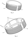
- Figure 3 shows the annular insert 20 comprising constraint means 21 and a slit 22 extending from a top of the insert 20 to a bottom of such insert 20.
- the constraint means 21 of the insert 20 preferably consist of an external thread 21a, or of male type.
- Insert 20 is configured to be inserted into housing 11 of the connecting element 1.
- the structural realization of insert 20 with dimensions complementary to housing 11 prevents the longitudinal translational movement of the insert 20 itself, when it is placed in the housing 11.
- the engagement of slit 22 with the main protrusion 15 of housing 11 prevents the rotary movement of insert 20.
- the insert 20 is housed in the housing 11 of the connecting element 1 through, for example, elastic deformation or combination of parts that can be stably associated with each other.
- Figure 2 shows a connecting element 1 with the insert 20 inserted into the housing 11.
- the connecting element 1 composed in this way ensures structural continuity between main body 10 and the insert 20.
- Figure 4 shows the annular insert 20 comprising constraint means 21 consisting of an external thread 21b, optionally different with respect to the one described above.
- the connecting element according to the invention may include inserts similar to the one described above, except for the type of constraint means installed, that can be for example interlocking or hinged, or also consist of external threads of any type, protocol, standard or size.
- the connecting element according to the invention may include inserts similar to the one described above, except for the type of constraint means installed, that can be for example interlocking or hinged, or also consist of external threads of any type, protocol, standard or size.
- insert 20 also includes a plurality of longitudinal elements 34, protruding from an internal surface, opposite to the threaded one, and extending along a direction connecting the top and bottom of such insert 20.
- These longitudinal elements 34 are configured to confer greater structural stability to the insert 20, when it is housed in housing 11 of the connecting element 1.
- insert 20 is made in a single piece.
- the connecting element 1 according to the invention can comprise inserts 20 made up of several pieces, which can be connected together by constraint means, such as interlocking systems or hinges.
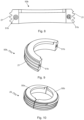
- Figures 6 to 10 show an insert 20 which can be assembled by the union of two distinct elements: a first element 50a and a second element 50b.
- the first element 50a is shown in front view in figure 6 and in perspective view in figure 7 ; it comprises constraint means 21, preferably consisting of an external or male type thread, and association means 51, preferably consisting of a male type interlocking system 51a, configured to interoperate with the second element 50b.
- the latter shown in front view in figure 8 and in perspective view in figure 9 , comprises constraint means 21 of the same type, standard or protocol of the constraint means 21 of the first element 50a, consisting preferably of an external or male type thread, and association means 51, preferably consisting of a female type interlocking system 51b, intended to the connection with the first element 50a.
- the first element 50a and the second element 50b have the shape of a semi-circumference.
- Figure 10 shows the insert 20 when the first element 50a and the second element 50b are connected together by association means 51.
- the insert 20 is configured to be inserted in correspondence of a housing 11 of the connection element 1 by interlocking.
- the connecting element 1 according to the invention can comprise inserts 20 that may be composed through the union of more than two elements.
- Figure 5 shows an embodiment of the connecting element 1 comprising a second housing 11 totally analogous to the one described above, preferably positioned at a second end of the main body 10.
- the main body 10 has at its center a side surface having an anti-slip conformation.
- the connecting element 1 is configured to receive at least two inserts 20.
- figure 5 shows the connecting element 1 with insert 20 inserted in housing 11.
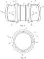
- At least one of the housings 11 of the connecting element 1 may comprise at least one additional protrusion 60, as shown in Figures 11 and 12 .
- the additional protrusion 60 is an interrupted protrusion, i.e. it is connected only to one between the top edge 12 and the bottom edge 13 of the housing 11. In other words, the additional protrusion 60 protrudes from the main body 10 and has a longitudinal extension lower than the distance between the top edge 12 and the bottom edge 13 of the housing 11.
- the main protrusion 15 and the three additional feedback 60 can be distributed in an equidistant way, meaning that they can be angularly spaced at the same distance.
- the windows 72 are made by means of interruption on the side wall of insert 20: unlike slit 22, windows 72 are small in size, enough to accommodate the additional protrusions 60.
- an insert 20 with three windows 72 is represented in a perspective bottom view in figure 13 and in a bottom view in figure 14 .
- the slit 22 and the windows 72 can be distributed in an equidistant way, or they can be angularly spaced of the same distance.
- Figure 15 shows connecting element 1 with insert 20, comprising three windows 72, inserted in housing 11.
- the engagement of the three additional protrusions 60 with the three windows 72 helps to prevent the rotary movement of insert 20 when inserted into housing 11, which ensures the structural stability of the connecting element 1.
- the connecting element 1 may include a main protrusion 15 made in the same way as an additional protrusion 60, i.e. may comprise a main protrusion 15 interrupted nearby the top edge of the housing and/or nearby the bottom edge, without this affecting the stability of the connecting element itself when receiving one or more inserts 20.
- all the main protrusions 15 represented in the attached figures are interrupted.
- the annular insert 20 represented in perspective top view in figure 16 and in perspective bottom view in figure 17 , can be provided with a circumferential relief 85, preferably placed nearby its top portion, protruding radially towards the center of the ring.
- This circumferential relief 85 is interrupted by the slit 22; its radial extension corresponds at least to the radial extension of the protrusions 15; 60.
- this circumferential relief 85 is configured to interoperate with the portion of the housing 11 corresponding to the interruption of the main protrusion 15.
- the annular insert 20 also further comprises blocking means 87, preferably consisting of at least one opening 87a, made by a partial and limited interruption of the bottom of insert 20. Therefore, the top of insert 20 is not interrupted in correspondence of opening 87a.
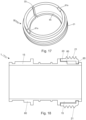
- FIG. 18 An embodiment of the connecting element 1 described above is represented in cross-section in figure 18 and in perspective view in figure 19 .
- the insert 20 acts as an idle ring when inserted in housing 11, being able to freely rotate with respect to the main body 10.
- the connecting element 1 may include a ferrule 90, represented in figures 20 and 21 respectively according to a perspective view and a section perspective view.
- the ferrule 90 comprises first constraint means 92 and second constraint means 94.
- the first constraint means 92 shall be complementary to the constraint means 21 means of insert 20. Preferably, they consist of an internal or female type thread.
- the second constraint means 94 consist of an internal or female type thread.
- Figure 22 shows a cross-section view of the connecting element 1 thus obtained, wherein the system consisting of insert 20 and ferrule 90 behaves once again as a single idle rotating body.
- the insert 20 can be inserted into the housing 11 of the connecting element 1 by means of elastic deformation, after which ferrule 90 can be constrained to this insert 20 by screwing. More in detail, an operator must lock the insert 20 in order to constraint the ferrule 90 to it by screwing. This ensures the continuity and structural stability of the connecting element 1.
- the blocking means 87 consisting of the opening 87a of insert 20, have the function of facilitating the operator in locking insert 20 during the locking and release phases of ferrule 90, possibly by means of appropriate tools configured to be inserted in the opening 87a, such as a screwdriver.
- blocking means 87 could include at least one protrusion to block the insert 20 during the locking and release phases of ferrule 90, possibly by means of appropriate tools.
- the connecting element provided comprising universal constraining means allows the interconnection of threaded connecting elements and the construction of systems comprising threaded joining elements in a versatile, reliable, efficient, easy, economical and reversible way.
- it allows an operator not to predetermine the type of thread and not to size the system a priori.
- it allows the conversion, repair and/or expansion of mechanical systems or piping systems in many sectors, such as mechanical, agricultural, electrical or hydraulic.
- connecting element according to the invention can easily be converted from a male connecting element to a female connecting element.
- each end of the connecting element according to the invention in its respective cylindrical hollow, can receive an additional appendix, such as a hose holder or a cable gland.
Landscapes
- Engineering & Computer Science (AREA)
- General Engineering & Computer Science (AREA)
- Mechanical Engineering (AREA)
- Mutual Connection Of Rods And Tubes (AREA)
- Quick-Acting Or Multi-Walled Pipe Joints (AREA)
Abstract
Description
- The present invention refers to a connecting element comprising universal constraint means.
- In the threading field, solutions are known that allow to interconnect components of different sizes. As an example, there exist connecting elements, having one or more ends, having a thread on one or more of their ends. The threads on the different ends can be different. These connecting elements may comprise male or female threads, depending on their realization, either external or internal at the end of the element.
- Despite numerous standardisation attempts by regulating organs, today several threading standards coexist, including:
- the ISO metric screw thread, commonly used for mechanical purposes, which follows UNI 4535-64;
- the Whitworth thread, alternative to the aforementioned ISO metric screw thread;
- the GAS thread, traditionally used for connecting pipes;
- EDISON and PG threads, usually used for electrical connections and for electrical wire conduits;
- the Lowenherz thread, used for measuring and optical instruments;
- the UST Unified Thread and the BA (British Association) thread, in which the dimensions are expressed in inches;
- the United States Standard thread, also called the SAE thread; and
- the triangular, square and/or trapezoidal thread.
- Therefore, the externally threaded ends, or of male type, are usually made according to a specific thread protocol or standard and are characterized by constructive parameters, such as the diameter and the thread pitch, that allow the joining with a corresponding internally threaded end, or of female type, made according to such specific protocol or thread standard and having construction parameters corresponding to those of the male type end.
- A problem with the existing connecting elements is that systems made by means of threaded connecting elements, such as mechanical systems or piping systems (hydraulic, electrical, etc.), are subject to numerous enlargements, repair and/or conversion. Therefore, the lack of versatility of the connecting elements emerges: once the standard and construction parameters of the thread have been chosen, it is not easy to interconnect threaded elements made according to different standards or according to the same standard but with different construction parameters. In fact, transition modules specifically adapted to the purpose are needed. This makes it difficult to extend, repair and/or convert the above systems. In fact, an operator who has to convert, repair and/or extend such systems is obliged to use threaded elements according to the standard of the system components and to follow the specific construction parameters already present. This limits the freedom to intervene of operators.
- A further problem with current connection technologies is that the type of thread has to be predetermined and the system has to be correctly sized a priori. In fact, an operator who wants to use threaded connecting elements is obliged to establish in advance first the type of standard to be used and then the specific construction parameters to be adopted. Once this choice is made, the operator is obliged to continue to use this standard and these construction parameters even if the system requires unforeseeable changes.
- The aim of this invention is therefore to eliminate the above-mentioned disadvantages.
- The invention achieves the aim by means of a structural modification allowing the connecting element to be associated with interchangeable components belonging to different standards.
- The main advantage obtained by means of this invention is basically the fact that it is possible to have at one's disposal a threaded connecting element that is versatile and compatible both with existing threading standards and with the various construction parameters of the same. Even in production phase it can be advantageous the possibility to concentrate the activity on the realization of a single connecting element that, appropriately equipped with interchangeable components, is suitable for use in various sectors, for example in the mechanical field, agricultural, electrical and hydraulic.
- A further advantage is the fact that it is possible to have at one's disposal a threaded connecting element that can be easily used for the expansion, repair and/or conversion of mechanical systems or piping systems.
- Another advantage is that the connecting element can be easily reconverted according to the invention, modifying the thread standard used.
- In addition, in some embodiments, the connecting element according to the invention can be easily converted from a male type connecting element to a female type connecting element, optionally rotating.
- Furthermore, the connecting element according to the invention can be configured by an operator according to his needs, freely choosing the type of standard or protocol to be adopted in each of the housing of the connecting element, through the insertion of appropriate inserts.
- Further advantages and features of the invention will be more apparent in the detailed description which follows, with reference to the accompanying drawings, which show an example, non-limiting embodiment, in which:
-
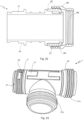
Figure 1 shows a frontal perspective view of a basic version of the invention; -
Figure 2 shows a frontal perspective view of a first alternative of the invention; -
Figure 3 shows a perspective view of a component of the invention; -
Figure 4 shows a perspective view of a second version of the component ofFigure 3 ; -
Figure 5 shows a perspective view of a second alternative of the invention; - Figures from 6 to 10 show a third version of the component of
Figure 3 ; -
Figures 11 and 12 respectively show a side view and a top view of a third variant of the invention; -
Figures 13 and 14 respectively show a perspective bottom view and a bottom view of a fourth version of the component ofFigure 3 ; -
Figure 15 shows in a side view the variant ofFigure 11 in a use condition; -
Figures 16 and17 respectively show a perspective top view and a perspective bottom of a fifth version of the component ofFigure 3 ; -
Figures 18 and19 respectively show a cross-section view and a perspective view of the variant ofFigure 11 in a second use condition; -
Figures 20 and 21 respectively show a side perspective view and a cross-section perspective view of an additional component of the invention; -
Figure 22 shows a cross-section view of the invention in a third use condition; -
Figure 23 shows a perspective view of a further variant of the invention. - Referring to
Figure 1 , it is possible to observe a connectingelement 1 according to the invention comprising amain body 10 wherein ahousing 11 is made. Thishousing 11 is preferably located at a first end of themain body 10. Thehousing 11 is delimited by atop edge 12 and by abottom edge 13, both protruding from a side surface ofmain body 10. In other words, thetop edge 12 andbottom edge 13 extend outwards with respect to the side surface of themain body 10. - Alternatively, the connecting element according to the invention may comprise a hollow housing in the main body. In particular, this housing can be obtained by narrowing the thickness of the side surface of the main body of the connecting element. In this case, the bottom edge and the top edge are made by the side surface itself of the main body.
- The
housing 11 also includes at least onemain protrusion 15, made along a direction connecting thetop edge 12 and thebottom edge 13 of thehousing 11. Thismain protrusion 15 also protrudes from the side surface of themain body 10 and it may affect theentire housing 11 or only part of it. - The
housing 11 is configured to receive at least oneannular insert 20. -
Figure 3 shows theannular insert 20 comprising constraint means 21 and aslit 22 extending from a top of theinsert 20 to a bottom ofsuch insert 20. - The constraint means 21 of the
insert 20 preferably consist of anexternal thread 21a, or of male type. -
Insert 20 is configured to be inserted intohousing 11 of the connectingelement 1. The structural realization ofinsert 20 with dimensions complementary tohousing 11 prevents the longitudinal translational movement of theinsert 20 itself, when it is placed in thehousing 11. The engagement ofslit 22 with themain protrusion 15 ofhousing 11 prevents the rotary movement ofinsert 20. Preferably, theinsert 20 is housed in thehousing 11 of the connectingelement 1 through, for example, elastic deformation or combination of parts that can be stably associated with each other. -
Figure 2 shows a connectingelement 1 with theinsert 20 inserted into thehousing 11. As mentioned above, the connectingelement 1 composed in this way ensures structural continuity betweenmain body 10 and theinsert 20. -
Figure 4 shows theannular insert 20 comprising constraint means 21 consisting of anexternal thread 21b, optionally different with respect to the one described above. - Sometimes, the connecting element according to the invention may include inserts similar to the one described above, except for the type of constraint means installed, that can be for example interlocking or hinged, or also consist of external threads of any type, protocol, standard or size.
- Sometimes, the connecting element according to the invention may include inserts similar to the one described above, except for the type of constraint means installed, that can be for example interlocking or hinged, or also consist of external threads of any type, protocol, standard or size.
- Preferably insert 20 also includes a plurality of
longitudinal elements 34, protruding from an internal surface, opposite to the threaded one, and extending along a direction connecting the top and bottom ofsuch insert 20. Theselongitudinal elements 34 are configured to confer greater structural stability to theinsert 20, when it is housed inhousing 11 of the connectingelement 1. - Preferably, insert 20 is made in a single piece.
- In some case the connecting
element 1 according to the invention can compriseinserts 20 made up of several pieces, which can be connected together by constraint means, such as interlocking systems or hinges. -
Figures 6 to 10 show aninsert 20 which can be assembled by the union of two distinct elements: afirst element 50a and asecond element 50b. Thefirst element 50a is shown in front view infigure 6 and in perspective view infigure 7 ; it comprises constraint means 21, preferably consisting of an external or male type thread, and association means 51, preferably consisting of a maletype interlocking system 51a, configured to interoperate with thesecond element 50b. The latter, shown in front view infigure 8 and in perspective view infigure 9 , comprises constraint means 21 of the same type, standard or protocol of the constraint means 21 of thefirst element 50a, consisting preferably of an external or male type thread, and association means 51, preferably consisting of a femaletype interlocking system 51b, intended to the connection with thefirst element 50a. - Preferably, the
first element 50a and thesecond element 50b have the shape of a semi-circumference. -
Figure 10 shows theinsert 20 when thefirst element 50a and thesecond element 50b are connected together by association means 51. - The
insert 20 is configured to be inserted in correspondence of ahousing 11 of theconnection element 1 by interlocking. - In other cases, the connecting
element 1 according to the invention can compriseinserts 20 that may be composed through the union of more than two elements. -
Figure 5 shows an embodiment of the connectingelement 1 comprising asecond housing 11 totally analogous to the one described above, preferably positioned at a second end of themain body 10. - Optionally, the
main body 10 has at its center a side surface having an anti-slip conformation. - As a consequence, the connecting
element 1 is configured to receive at least two inserts 20. For example,figure 5 shows the connectingelement 1 withinsert 20 inserted inhousing 11. - In some cases, at least one of the
housings 11 of the connectingelement 1 may comprise at least oneadditional protrusion 60, as shown inFigures 11 and 12 . - The
additional protrusion 60 is an interrupted protrusion, i.e. it is connected only to one between thetop edge 12 and thebottom edge 13 of thehousing 11. In other words, theadditional protrusion 60 protrudes from themain body 10 and has a longitudinal extension lower than the distance between thetop edge 12 and thebottom edge 13 of thehousing 11. - Preferably the
additional protrusion 60 protrudes from the side surface of themain body 10 and is realized along a direction connecting respectively thetop edge 12 and thebottom edge 13 of at least one of thehousings 11. Optionally, this direction is orthogonal to thetop edge 12 andbottom edge 13. - For example, in
figures 11 and 12 each of thehousings 11 comprise respectively amain protrusion 15 and threeadditional protrusions 60. - The
main protrusion 15 and the threeadditional feedback 60 can be distributed in an equidistant way, meaning that they can be angularly spaced at the same distance. - In general, the connecting
element 1 may comprise amain body 10 provided with an arbitrary number of housings, such as illustrated infigure 23 , and each housing may comprise a different number ofadditional protrusions 60, also positioned differently with respect to what was described above. - In the event that a connecting
element 1, comprising one or moreadditional protrusions 60, has to be associated with anannular insert 20, the latter shall be provided with one ormore windows 72 made in correspondence of theadditional protrusions 60. - The
windows 72 are made by means of interruption on the side wall of insert 20: unlikeslit 22,windows 72 are small in size, enough to accommodate theadditional protrusions 60. - As an example, an
insert 20 with threewindows 72 is represented in a perspective bottom view infigure 13 and in a bottom view infigure 14 . - The
slit 22 and thewindows 72 can be distributed in an equidistant way, or they can be angularly spaced of the same distance. -
Figure 15 shows connecting element 1 withinsert 20, comprising threewindows 72, inserted inhousing 11. The engagement of the threeadditional protrusions 60 with the threewindows 72 helps to prevent the rotary movement ofinsert 20 when inserted intohousing 11, which ensures the structural stability of the connectingelement 1. - The connecting
element 1 may include amain protrusion 15 made in the same way as anadditional protrusion 60, i.e. may comprise amain protrusion 15 interrupted nearby the top edge of the housing and/or nearby the bottom edge, without this affecting the stability of the connecting element itself when receiving one or more inserts 20. As an example, all themain protrusions 15 represented in the attached figures are interrupted. - The use of interrupted
main protrusions 15 on themain body 10 is well suited to the possibility of using the connectingelement 1 even with the characteristics of a female type junction. In this perspective, theannular insert 20, represented in perspective top view infigure 16 and in perspective bottom view infigure 17 , can be provided with acircumferential relief 85, preferably placed nearby its top portion, protruding radially towards the center of the ring. Thiscircumferential relief 85 is interrupted by theslit 22; its radial extension corresponds at least to the radial extension of theprotrusions 15; 60. In fact, thiscircumferential relief 85 is configured to interoperate with the portion of thehousing 11 corresponding to the interruption of themain protrusion 15. - The
annular insert 20 also further comprises blocking means 87, preferably consisting of at least oneopening 87a, made by a partial and limited interruption of the bottom ofinsert 20. Therefore, the top ofinsert 20 is not interrupted in correspondence ofopening 87a. - In
figures 16 and17 , aninsert 20 comprising twoopenings 87a is shown as an example. - An embodiment of the connecting
element 1 described above is represented in cross-section infigure 18 and in perspective view infigure 19 . In this case, thanks to its structural conformation and to the presence of thecircumferential relief 85, theinsert 20 acts as an idle ring when inserted inhousing 11, being able to freely rotate with respect to themain body 10. - Even if the circumferential relief was made nearby to the bottom of
insert 20, the same functionality would be maintained as long as blocking means 87 remained nearby to that bottom edge. - To assume the functionality of a female connection, the connecting
element 1 may include aferrule 90, represented infigures 20 and 21 respectively according to a perspective view and a section perspective view. - The
ferrule 90 comprises first constraint means 92 and second constraint means 94. The first constraint means 92 shall be complementary to the constraint means 21 means ofinsert 20. Preferably, they consist of an internal or female type thread. The second constraint means 94 consist of an internal or female type thread. -
Figure 22 shows a cross-section view of the connectingelement 1 thus obtained, wherein the system consisting ofinsert 20 andferrule 90 behaves once again as a single idle rotating body. By way of example, theinsert 20 can be inserted into thehousing 11 of the connectingelement 1 by means of elastic deformation, after which ferrule 90 can be constrained to thisinsert 20 by screwing. More in detail, an operator must lock theinsert 20 in order to constraint theferrule 90 to it by screwing. This ensures the continuity and structural stability of the connectingelement 1. - The blocking means 87, consisting of the
opening 87a ofinsert 20, have the function of facilitating the operator in lockinginsert 20 during the locking and release phases offerrule 90, possibly by means of appropriate tools configured to be inserted in theopening 87a, such as a screwdriver. - Alternatively, blocking means 87 could include at least one protrusion to block the
insert 20 during the locking and release phases offerrule 90, possibly by means of appropriate tools. - Therefore, the connecting element provided comprising universal constraining means according to the invention allows the interconnection of threaded connecting elements and the construction of systems comprising threaded joining elements in a versatile, reliable, efficient, easy, economical and reversible way. In particular, it allows an operator not to predetermine the type of thread and not to size the system a priori. Moreover, thanks to the simple but effective replacement of inserts, it allows the conversion, repair and/or expansion of mechanical systems or piping systems in many sectors, such as mechanical, agricultural, electrical or hydraulic.
- It should be noted that the structural seal of the inserts is ensured, while any hydraulic seal must be ensured by the use of suitable seals, for example flat or toroidal, optionally elastic deformable.
- It is also emphasized that the connecting element according to the invention can easily be converted from a male connecting element to a female connecting element.
- It should be noted how each end of the connecting element according to the invention, in its respective cylindrical hollow, can receive an additional appendix, such as a hose holder or a cable gland.
Claims (12)
- Connecting element comprising a main body (10) in which it is made at least one housing (11), delimited by a top edge (12) and by a bottom edge (13), characterised in that the housing (11) comprises at least one main protrusion (15) made along a direction connecting the top edge (12) and the bottom edge (13) of the housing (11).
- Connecting element according to claim 1, characterised by comprising at least one annular insert (20) housed in the housing (11), said insert (20) comprising outer constraint means (21).
- Connecting element according to claim 1 or 2, characterised in that the constraint means (21) of the insert (20) consist of an outer thread (21a, 21b).
- Connecting element according to claim 2 or 3, characterised in that the insert (20) comprises a slit (22).
- Connecting element according to claim 2 or 3, characterised in that the insert (20) comprises at least two elements (50a, 50b) provided with mutually complementary association means (51a, 51b).
- Connecting element according to any one of claims from 2 to 5, characterised in that the insert (20) comprises at least one window (72), made on a sidewall thereof.
- Connecting element according to claim 6, characterised in that at least one housing (11) comprises at least one interrupted additional protrusion (60) complementary to a respective window (72), only connected to one between the top edge (12) and the bottom edge (13).
- Connecting element according to any one of claims from 1 to 7, characterised in that the main protrusion (15) is an interrupted protrusion, only connected to one between the top edge (12) and the bottom edge (13) of the housing (11).
- Connecting element according to claim 8, characterised in that the insert (20) comprises a circumferential relief (85), radially protruding towards the center of the insert (20) with a radial extension that is at least equal to the one of the protrusion (15; 60) and blocking means (87), made nearby the bottom of the insert (20).
- Connecting element according to claim 9, characterised in that the blocking means (87) of the insert (20) consist of at least one opening (87a), made by an interruption of the bottom of the insert (20).
- Connecting element according to claim 9 or 10, characterised by comprising a ferrule (90) provided with first constraint means (92) and second constraint means (94), wherein first constraint means (92) are complementary to the constraint means (21) of the insert (20) and second constraint means (94) consist of an inner thread.
- Connecting element mounting kit, characterised by comprising:- at least one main body (10) according to any one of claims 1, 7, 8;- at least one annular insert (20) according to any one of claims 2, 3, 4, 5, 6, 9, 10; and/or- at least one ferrule (90) according to claim 11.
Applications Claiming Priority (1)
| Application Number | Priority Date | Filing Date | Title |
|---|---|---|---|
| IT102023000004398A IT202300004398A1 (en) | 2023-03-09 | 2023-03-09 | CONNECTING ELEMENT |
Publications (3)
| Publication Number | Publication Date |
|---|---|
| EP4428379A1 true EP4428379A1 (en) | 2024-09-11 |
| EP4428379C0 EP4428379C0 (en) | 2026-02-18 |
| EP4428379B1 EP4428379B1 (en) | 2026-02-18 |
Family
ID=86469004
Family Applications (1)
| Application Number | Title | Priority Date | Filing Date |
|---|---|---|---|
| EP24020073.3A Active EP4428379B1 (en) | 2023-03-09 | 2024-03-08 | Connecting element |
Country Status (3)
| Country | Link |
|---|---|
| US (1) | US12455024B2 (en) |
| EP (1) | EP4428379B1 (en) |
| IT (1) | IT202300004398A1 (en) |
Families Citing this family (2)
| Publication number | Priority date | Publication date | Assignee | Title |
|---|---|---|---|---|
| JP1726596S (en) * | 2022-03-14 | 2022-10-05 | plumbing fittings | |
| USD1114200S1 (en) * | 2023-12-15 | 2026-02-17 | Lupe Estrada | Fuel-air mixer |
Citations (3)
| Publication number | Priority date | Publication date | Assignee | Title |
|---|---|---|---|---|
| US5160172A (en) * | 1990-12-18 | 1992-11-03 | Abb Vetco Gray Inc. | Threaded latch ring tubular connector |
| US20140024250A1 (en) * | 2012-05-15 | 2014-01-23 | Siemens Aktiengesellschaft | Underwater Electrical Connection And Termination Assemblies |
| CN216754168U (en) * | 2021-11-24 | 2022-06-17 | 浙江强伟五金有限公司 | Rotary plastic locking inner plug assembly |
Family Cites Families (9)
| Publication number | Priority date | Publication date | Assignee | Title |
|---|---|---|---|---|
| US944877A (en) * | 1909-06-08 | 1909-12-28 | Ernest August Koschinski | Coupling. |
| US3376054A (en) * | 1964-12-07 | 1968-04-02 | Phillips Petroleum Co | Conduit fittings having band clamping means |
| US4007953A (en) * | 1975-09-10 | 1977-02-15 | International Telephone And Telegraph Corporation | Removable captive coupling nut assembly |
| US4291906A (en) * | 1979-10-19 | 1981-09-29 | Donbavand Martin H | Device for locking and sealing standard cone-socket joints for laboratory apparatus |
| US4634154A (en) * | 1985-02-06 | 1987-01-06 | Fmc Corporation | Lightweight integral pup joint with split female sub |
| US4728130A (en) * | 1987-01-12 | 1988-03-01 | Corzine George S | Locking assembly for push-on fittings |
| US5266050A (en) * | 1991-12-04 | 1993-11-30 | Arlington Industries, Inc. | Quick-connect fitting for electrical junction box |
| US5547229A (en) * | 1994-05-13 | 1996-08-20 | Eidsmore; Paul G. | Fluid coupling assembly |
| US9490619B2 (en) * | 2012-10-25 | 2016-11-08 | Bridgeport Fittings, Inc. | Push-on liquidtight conduit fitting |
-
2023
- 2023-03-09 IT IT102023000004398A patent/IT202300004398A1/en unknown
-
2024
- 2024-03-08 US US18/599,908 patent/US12455024B2/en active Active
- 2024-03-08 EP EP24020073.3A patent/EP4428379B1/en active Active
Patent Citations (4)
| Publication number | Priority date | Publication date | Assignee | Title |
|---|---|---|---|---|
| US5160172A (en) * | 1990-12-18 | 1992-11-03 | Abb Vetco Gray Inc. | Threaded latch ring tubular connector |
| US20140024250A1 (en) * | 2012-05-15 | 2014-01-23 | Siemens Aktiengesellschaft | Underwater Electrical Connection And Termination Assemblies |
| CN216754168U (en) * | 2021-11-24 | 2022-06-17 | 浙江强伟五金有限公司 | Rotary plastic locking inner plug assembly |
| FR3129278A3 (en) * | 2021-11-24 | 2023-05-26 | Zhejiang Qiangwei Hardware Co., Ltd. | PLASTIC ROTARY LOCK INTERNAL PLUG ASSEMBLY |
Also Published As
| Publication number | Publication date |
|---|---|
| US20240301974A1 (en) | 2024-09-12 |
| US12455024B2 (en) | 2025-10-28 |
| EP4428379C0 (en) | 2026-02-18 |
| IT202300004398A1 (en) | 2024-09-09 |
| EP4428379B1 (en) | 2026-02-18 |
Similar Documents
| Publication | Publication Date | Title |
|---|---|---|
| US12455024B2 (en) | Connecting element | |
| US6849803B1 (en) | Electrical connector | |
| CA2581158C (en) | Rotatable liquid-tight conduit connector assembly | |
| US6043432A (en) | Snap in cable connector | |
| US5422437A (en) | Electrical connector assembly | |
| US6908123B2 (en) | Bayonet quick coupler | |
| RU2231184C2 (en) | Plug-and-socket connection | |
| US7955125B1 (en) | Electrical connector with one end threadably connected to a junction box and other end configured to be connected to a mating electrical connector | |
| US9638356B2 (en) | Wall lead-through | |
| US20090142952A1 (en) | Conversion adapter for connector and connector | |
| CA2954326C (en) | Plug housing and assembly | |
| EP2227649B1 (en) | Pipe fitting | |
| US6593531B2 (en) | Add-on housing | |
| EP1798584B1 (en) | Latching trough-coupling system | |
| US20040061334A1 (en) | Plug-in connector for plumbing fixtures | |
| US20060022461A1 (en) | Tubular reducer fitting for ENT tubing | |
| EP1653583B1 (en) | Fitting for helical protection sheaths | |
| US4673234A (en) | Connector/adapter assembly for flexible conduit or electrical cable | |
| BR102024004650A2 (en) | CONNECTION ELEMENT | |
| JP4504154B2 (en) | Connector removal prevention tool | |
| CA3196349A1 (en) | Connection device for a peripherally ribbed pipe | |
| IT202300000939U1 (en) | CONNECTING ELEMENT | |
| KR102932673B1 (en) | Connector and Bushing Integrated Conduit Connection Structure Compatible with Various Types of Conduit | |
| KR101560140B1 (en) | Water-proof optical connector | |
| EP1724511B1 (en) | Quick connector with a retainer |
Legal Events
| Date | Code | Title | Description |
|---|---|---|---|
| PUAI | Public reference made under article 153(3) epc to a published international application that has entered the european phase |
Free format text: ORIGINAL CODE: 0009012 |
|
| STAA | Information on the status of an ep patent application or granted ep patent |
Free format text: STATUS: THE APPLICATION HAS BEEN PUBLISHED |
|
| AK | Designated contracting states |
Kind code of ref document: A1 Designated state(s): AL AT BE BG CH CY CZ DE DK EE ES FI FR GB GR HR HU IE IS IT LI LT LU LV MC ME MK MT NL NO PL PT RO RS SE SI SK SM TR |
|
| STAA | Information on the status of an ep patent application or granted ep patent |
Free format text: STATUS: REQUEST FOR EXAMINATION WAS MADE |
|
| 17P | Request for examination filed |
Effective date: 20250306 |
|
| RAV | Requested validation state of the european patent: fee paid |
Extension state: MD Effective date: 20250306 Extension state: GE Effective date: 20250306 |
|
| GRAP | Despatch of communication of intention to grant a patent |
Free format text: ORIGINAL CODE: EPIDOSNIGR1 |
|
| STAA | Information on the status of an ep patent application or granted ep patent |
Free format text: STATUS: GRANT OF PATENT IS INTENDED |
|
| RIC1 | Information provided on ipc code assigned before grant |
Ipc: F16B 7/18 20060101AFI20250827BHEP |
|
| INTG | Intention to grant announced |
Effective date: 20250918 |
|
| GRAS | Grant fee paid |
Free format text: ORIGINAL CODE: EPIDOSNIGR3 |
|
| GRAA | (expected) grant |
Free format text: ORIGINAL CODE: 0009210 |
|
| STAA | Information on the status of an ep patent application or granted ep patent |
Free format text: STATUS: THE PATENT HAS BEEN GRANTED |
|
| AK | Designated contracting states |
Kind code of ref document: B1 Designated state(s): AL AT BE BG CH CY CZ DE DK EE ES FI FR GB GR HR HU IE IS IT LI LT LU LV MC ME MK MT NL NO PL PT RO RS SE SI SK SM TR |
|
| REG | Reference to a national code |
Ref country code: CH Ref legal event code: F10 Free format text: ST27 STATUS EVENT CODE: U-0-0-F10-F00 (AS PROVIDED BY THE NATIONAL OFFICE) Effective date: 20260218 Ref country code: GB Ref legal event code: FG4D |
|
| REG | Reference to a national code |
Ref country code: IE Ref legal event code: FG4D |
|
| REG | Reference to a national code |
Ref country code: DE Ref legal event code: R096 Ref document number: 602024002542 Country of ref document: DE |
|
| U01 | Request for unitary effect filed |
Effective date: 20260304 |
|
| U07 | Unitary effect registered |
Designated state(s): AT BE BG DE DK EE FI FR IT LT LU LV MT NL PT RO SE SI Effective date: 20260310 |
|
| PGFP | Annual fee paid to national office [announced via postgrant information from national office to epo] |
Ref country code: AT Payment date: 20260301 Year of fee payment: 3 |
|
| REG | Reference to a national code |
Ref country code: CH Ref legal event code: R17 Free format text: ST27 STATUS EVENT CODE: U-0-0-R10-R17 (AS PROVIDED BY THE NATIONAL OFFICE) Effective date: 20260429 |
|
| U20 | Renewal fee for the european patent with unitary effect paid |
Year of fee payment: 3 Effective date: 20260527 |
|
| PG25 | Lapsed in a contracting state [announced via postgrant information from national office to epo] |
Ref country code: RS Free format text: LAPSE BECAUSE OF FAILURE TO SUBMIT A TRANSLATION OF THE DESCRIPTION OR TO PAY THE FEE WITHIN THE PRESCRIBED TIME-LIMIT Effective date: 20260518 |
|
| PG25 | Lapsed in a contracting state [announced via postgrant information from national office to epo] |
Ref country code: ES Free format text: LAPSE BECAUSE OF FAILURE TO SUBMIT A TRANSLATION OF THE DESCRIPTION OR TO PAY THE FEE WITHIN THE PRESCRIBED TIME-LIMIT Effective date: 20260218 |
|
| PG25 | Lapsed in a contracting state [announced via postgrant information from national office to epo] |
Ref country code: PL Free format text: LAPSE BECAUSE OF FAILURE TO SUBMIT A TRANSLATION OF THE DESCRIPTION OR TO PAY THE FEE WITHIN THE PRESCRIBED TIME-LIMIT Effective date: 20260218 |
|
| PG25 | Lapsed in a contracting state [announced via postgrant information from national office to epo] |
Ref country code: GR Free format text: LAPSE BECAUSE OF FAILURE TO SUBMIT A TRANSLATION OF THE DESCRIPTION OR TO PAY THE FEE WITHIN THE PRESCRIBED TIME-LIMIT Effective date: 20260519 |
|
| PG25 | Lapsed in a contracting state [announced via postgrant information from national office to epo] |
Ref country code: NO Free format text: LAPSE BECAUSE OF FAILURE TO SUBMIT A TRANSLATION OF THE DESCRIPTION OR TO PAY THE FEE WITHIN THE PRESCRIBED TIME-LIMIT Effective date: 20260518 |
|
| PG25 | Lapsed in a contracting state [announced via postgrant information from national office to epo] |
Ref country code: HR Free format text: LAPSE BECAUSE OF FAILURE TO SUBMIT A TRANSLATION OF THE DESCRIPTION OR TO PAY THE FEE WITHIN THE PRESCRIBED TIME-LIMIT Effective date: 20260218 |
|
| PG25 | Lapsed in a contracting state [announced via postgrant information from national office to epo] |
Ref country code: IS Free format text: LAPSE BECAUSE OF FAILURE TO SUBMIT A TRANSLATION OF THE DESCRIPTION OR TO PAY THE FEE WITHIN THE PRESCRIBED TIME-LIMIT Effective date: 20260618 |