EP4428374A1 - Propeller fan, blower, and air conditioner - Google Patents
Propeller fan, blower, and air conditioner Download PDFInfo
- Publication number
- EP4428374A1 EP4428374A1 EP21963292.4A EP21963292A EP4428374A1 EP 4428374 A1 EP4428374 A1 EP 4428374A1 EP 21963292 A EP21963292 A EP 21963292A EP 4428374 A1 EP4428374 A1 EP 4428374A1
- Authority
- EP
- European Patent Office
- Prior art keywords
- locus
- blade
- propeller fan
- respect
- rotation shaft
- Prior art date
- Legal status (The legal status is an assumption and is not a legal conclusion. Google has not performed a legal analysis and makes no representation as to the accuracy of the status listed.)
- Withdrawn
Links
Images


Classifications
-
- F—MECHANICAL ENGINEERING; LIGHTING; HEATING; WEAPONS; BLASTING
- F04—POSITIVE - DISPLACEMENT MACHINES FOR LIQUIDS; PUMPS FOR LIQUIDS OR ELASTIC FLUIDS
- F04D—NON-POSITIVE-DISPLACEMENT PUMPS
- F04D29/00—Details, component parts, or accessories
- F04D29/26—Rotors specially for elastic fluids
- F04D29/32—Rotors specially for elastic fluids for axial flow pumps
- F04D29/38—Blades
- F04D29/384—Blades characterised by form
-
- F—MECHANICAL ENGINEERING; LIGHTING; HEATING; WEAPONS; BLASTING
- F04—POSITIVE - DISPLACEMENT MACHINES FOR LIQUIDS; PUMPS FOR LIQUIDS OR ELASTIC FLUIDS
- F04D—NON-POSITIVE-DISPLACEMENT PUMPS
- F04D29/00—Details, component parts, or accessories
- F04D29/26—Rotors specially for elastic fluids
- F04D29/32—Rotors specially for elastic fluids for axial flow pumps
- F04D29/38—Blades
- F04D29/384—Blades characterised by form
- F04D29/386—Skewed blades
-
- F—MECHANICAL ENGINEERING; LIGHTING; HEATING; WEAPONS; BLASTING
- F04—POSITIVE - DISPLACEMENT MACHINES FOR LIQUIDS; PUMPS FOR LIQUIDS OR ELASTIC FLUIDS
- F04D—NON-POSITIVE-DISPLACEMENT PUMPS
- F04D29/00—Details, component parts, or accessories
- F04D29/40—Casings; Connections of working fluid
- F04D29/52—Casings; Connections of working fluid for axial pumps
- F04D29/522—Casings; Connections of working fluid for axial pumps especially adapted for elastic fluid pumps
- F04D29/526—Details of the casing section radially opposing blade tips
-
- F—MECHANICAL ENGINEERING; LIGHTING; HEATING; WEAPONS; BLASTING
- F05—INDEXING SCHEMES RELATING TO ENGINES OR PUMPS IN VARIOUS SUBCLASSES OF CLASSES F01-F04
- F05D—INDEXING SCHEME FOR ASPECTS RELATING TO NON-POSITIVE-DISPLACEMENT MACHINES OR ENGINES, GAS-TURBINES OR JET-PROPULSION PLANTS
- F05D2240/00—Components
- F05D2240/20—Rotors
- F05D2240/30—Characteristics of rotor blades, i.e. of any element transforming dynamic fluid energy to or from rotational energy and being attached to a rotor
- F05D2240/303—Characteristics of rotor blades, i.e. of any element transforming dynamic fluid energy to or from rotational energy and being attached to a rotor related to the leading edge of a rotor blade
-
- F—MECHANICAL ENGINEERING; LIGHTING; HEATING; WEAPONS; BLASTING
- F05—INDEXING SCHEMES RELATING TO ENGINES OR PUMPS IN VARIOUS SUBCLASSES OF CLASSES F01-F04
- F05D—INDEXING SCHEME FOR ASPECTS RELATING TO NON-POSITIVE-DISPLACEMENT MACHINES OR ENGINES, GAS-TURBINES OR JET-PROPULSION PLANTS
- F05D2240/00—Components
- F05D2240/20—Rotors
- F05D2240/30—Characteristics of rotor blades, i.e. of any element transforming dynamic fluid energy to or from rotational energy and being attached to a rotor
- F05D2240/304—Characteristics of rotor blades, i.e. of any element transforming dynamic fluid energy to or from rotational energy and being attached to a rotor related to the trailing edge of a rotor blade
Definitions
- the present disclosure relates to a propeller fan, a blower, and an air conditioner.
- the PLT 1 describes a propeller fan.
- the propeller fan includes a rotation shaft, and a blade rotating around the rotation shaft.
- the present disclosure is intended to solve the problem as described above.
- An object of the present disclosure is to obtain a propeller fan advantageous in energy efficiency.
- a propeller fan according to the present disclosure includes a rotation shaft, and a blade rotating around the rotation shaft.
- a first locus connecting a leading edge of the blade and an outer peripheral end of the blade is tilted with respect to a second locus connecting the center of the rotation shaft and the leading edge so that the outer peripheral end side is inclined toward a trailing side.
- a third locus connecting a root of the blade and an outer peripheral end of the blade is tilted with respect to a fourth locus connecting a center of the rotation shaft and the root so that the outer peripheral end side is inclined toward a trailing side.
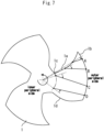
- Fig. 1 is a side view illustrating a propeller fan of Embodiment 1.
- Fig. 2 is a front view illustrating the propeller fan of Embodiment 1.
- the propeller fan according to the present disclosure includes a shaft, and a blade 1 rotating around the rotation shaft.
- the rotation shaft is formed as a boss 2 as an example.
- the propeller fan according to the present embodiment is characterized by the shape of the blade 1. Specifically, at the same position in an axial direction of the rotation shaft, a first locus connecting a leading edge 1a of the blade 1 and an outer peripheral end 1b of the blade 1 is tilted with respect to a second locus connecting a center of the rotation shaft and the leading edge 1a so that the outer peripheral end 1b side is inclined toward a trailing side. Alternatively, at the same position in the axial direction of the rotation shaft, a third locus connecting a root 1c of the blade 1 and the outer peripheral end 1b of the blade 1 is tilted with respect to a fourth locus connecting the center of the rotation shaft and the root 1c so that the outer peripheral end 1b side is inclined toward the trailing side.
- Figs. 1 and 2 illustrate the characteristic of the shape described above.
- lines indicated by reference characters A, B, and C illustrate "the same position in the axial direction of the rotation shaft".
- the first locus and the third locus described above are shown as solid-line loci in Fig. 2 .
- the second locus and the fourth locus are shown as dashed-line loci in Fig. 2 .
- Reference characters A, B, and C in Fig. 2 correspond to reference characters A, B, and C in Fig. 1 , respectively.
- a blade surface where the blade 1 receives a flow F from a fan side face containing a radial component of the propeller fan faces the flow F to no small extent. Accordingly, energy can be efficiently given from the blade 1 to the flow F from the fan side face. According to the present embodiment, it is possible to obtain the propeller fan advantageous in energy efficiency.
- the propeller fan according to the present embodiment is applicable, for example, to any blower.
- a blower is a device that performs air blowing using an air current generated by a propeller fan.
- Fig. 3 is a diagram showing an application example of the propeller fan of Embodiment 1.
- the propeller fan according to the present embodiment can be installed, for example, in an outdoor unit 3 of an air conditioner 10.
- the air conditioner 10 includes an indoor unit 11 that performs, for example, air blowing into a room, and an outdoor unit 3 connected to the indoor unit 11 through a pipe 12.
- the propeller fan applied to the outdoor unit 3 is, for example, covered with a semi-open type bell mouth 4 that does not cover the upstream side of the propeller fan. Note that, also when the propeller fan is applied to a device other than the outdoor unit 3, the propeller can be covered with the semi-open type bell mouth 4 to be used.
- the semi-open type bell mouth 4 covers a part of the blade 1.
- a region in which the blade 1 is not covered with the bell mouth that is, a region R1 in which the blade 1 and the bell mouth 4 do not overlap, a large flow F from the fan side face to the blade 1 can occur.
- the tilt of the first locus with respect to the second locus described above be formed at least in the region R1 in which the bell mouth 4 and the blade 1 do not overlap.
- the tilt of the third locus with respect to the fourth locus be formed at least in the region R1 in which the bell mouth 4 and the blade 1 do not overlap.
- Fig. 4 is a front view illustrating a first modification of the propeller fan of Embodiment 1.
- the flow F from the fan side face containing the radial component tends to become larger toward the downstream side, that is, the trailing edge 1d side of the blade 1.
- the tilt of the first locus with respect to the second locus described above may be increased toward the trailing edge 1d side of the blade 1.
- the tilt of the third locus with respect to the fourth locus may be increased toward the trailing edge 1d side of the blade 1.
- the tilt of the third locus with respect to the fourth locus may be made larger than the tilt of the first locus with respect to the second locus.
- the tilt of the first locus with respect to the second locus does not necessarily have to increase toward the trailing edge 1d side of the blade 1 over the entire area.
- the tilt of the third locus with respect to the fourth locus does not necessarily have to increase toward the trailing edge 1d side of the blade 1 over the entire area.
- Fig. 5 is a diagram showing an application example of a second modification of the propeller fan of Embodiment 1.
- Fig. 6 is a front view illustrating a second modification of the propeller fan of Embodiment 1.
- Lines indicated by reference characters A, B, C, and D in Fig. 5 illustrate "the same position in the axial direction of the rotation shaft" as with the lines indicated by the respective reference characters in Fig. 1 .
- Reference characters A, B, C, and D in Fig. 6 correspond to reference characters A, B, C, and D in Fig. 5 , respectively.
- the tilt to the trailing side of the first locus with respect to the second locus may be made smaller in the region R2 in which the bell mouth 4 and the blade 1 overlap than in the region R1 in which the bell mouth 4 and the blade 1 do not overlap.
- the tilt to the rear of the third locus with respect to the fourth locus may be made smaller in the region R2 in which the bell mouth 4 and the blade 1 overlap than in the region R1 in which the bell mouth 4 and the blade 1 do not overlap.
- the tilt to the trailing side of the third locus with respect to the fourth locus in the region R2 in which the bell mouth 4 and the blade 1 overlap may be made smaller than the tilt to the trailing side of the first locus with respect to the second locus in the region R1 in which the bell mouth 4 and the blade 1 do not overlap. According to this configuration, it is possible to provide the propeller fan having higher energy efficiency.
- the third locus may be tilted with respect to the fourth locus so that the outer peripheral end side of the blade 1 is inclined toward the leading side.
- the first locus may be tilted with respect to the second locus so that the outer peripheral end side of the blade 1 is inclined toward the leading side.
- Fig. 7 is a front view illustrating a third modification of the propeller fan of Embodiment 1.
- the propeller fan according to the present disclosure is also applicable, for example, to a bossless form in which the blades 1 are directly and integrally connected to each other without the boss 2.
- the rotation shaft is formed on the center of the integrally connected blades 1.
- the propeller fan according to the present disclosure can be used in various types of blowers or outdoor units of air conditioners.
Landscapes
- Engineering & Computer Science (AREA)
- Mechanical Engineering (AREA)
- General Engineering & Computer Science (AREA)
- Structures Of Non-Positive Displacement Pumps (AREA)
Abstract
Description
- The present disclosure relates to a propeller fan, a blower, and an air conditioner.
- PLT 1 describes a propeller fan. The propeller fan includes a rotation shaft, and a blade rotating around the rotation shaft.
- [PLT 1]
JP 4467952 B2 - In the conventional propeller fan described in
PLT 1 and the like, sufficient energy cannot be given from the blade to a flow from the side face of the propeller fan. - The present disclosure is intended to solve the problem as described above. An object of the present disclosure is to obtain a propeller fan advantageous in energy efficiency.
- A propeller fan according to the present disclosure includes a rotation shaft, and a blade rotating around the rotation shaft.
- At the same position in an axial direction of the rotation shaft, a first locus connecting a leading edge of the blade and an outer peripheral end of the blade is tilted with respect to a second locus connecting the center of the rotation shaft and the leading edge so that the outer peripheral end side is inclined toward a trailing side.
- Alternatively, at the same position in an axial direction of the rotation shaft part, a third locus connecting a root of the blade and an outer peripheral end of the blade is tilted with respect to a fourth locus connecting a center of the rotation shaft and the root so that the outer peripheral end side is inclined toward a trailing side.
- According to the present disclosure, it is possible to obtain a propeller fan advantageous in energy efficiency.
-
- [
Fig. 1 ]
Fig. 1 is a side view illustrating a propeller fan of Embodiment 1. - [
Fig. 2 ]
Fig. 2 is a front view illustrating the propeller fan of Embodiment 1. - [
Fig. 3 ]
Fig. 3 is a diagram showing an application example of the propeller fan ofEmbodiment 1. - [
Fig. 4 ]
Fig. 4 is a front view illustrating a first modification of the propeller fan of Embodiment 1. - [
Fig. 5 ]
Fig. 5 is a diagram showing an application example of a second modification of the propeller fan ofEmbodiment 1. - [
Fig. 6 ]
Fig. 6 is a front view illustrating the second modification of the propeller fan of Embodiment 1. - [
Fig. 7 ]
Fig. 7 is a front view illustrating a third modification of the propeller fan of Embodiment. - Hereinbelow, an embodiment will be described with reference to the accompanying drawings. Note that common or corresponding elements will be denoted by the same reference signs throughout the drawings, and redundant description will be simplified or omitted in the present disclosure. Note that the present disclosure is not limited to the embodiment described below and can include all combinations and modifications of the configurations disclosed in the following embodiment.
-
Fig. 1 is a side view illustrating a propeller fan of Embodiment 1.Fig. 2 is a front view illustrating the propeller fan of Embodiment 1. The propeller fan according to the present disclosure includes a shaft, and ablade 1 rotating around the rotation shaft. The rotation shaft is formed as aboss 2 as an example. - The propeller fan according to the present embodiment is characterized by the shape of the
blade 1. Specifically, at the same position in an axial direction of the rotation shaft, a first locus connecting a leadingedge 1a of theblade 1 and an outerperipheral end 1b of theblade 1 is tilted with respect to a second locus connecting a center of the rotation shaft and the leadingedge 1a so that the outerperipheral end 1b side is inclined toward a trailing side. Alternatively, at the same position in the axial direction of the rotation shaft, a third locus connecting aroot 1c of theblade 1 and the outerperipheral end 1b of theblade 1 is tilted with respect to a fourth locus connecting the center of the rotation shaft and theroot 1c so that the outerperipheral end 1b side is inclined toward the trailing side. -
Figs. 1 and 2 illustrate the characteristic of the shape described above. InFig. 1 , lines indicated by reference characters A, B, and C illustrate "the same position in the axial direction of the rotation shaft". The first locus and the third locus described above are shown as solid-line loci inFig. 2 . Also, the second locus and the fourth locus are shown as dashed-line loci inFig. 2 . Reference characters A, B, and C inFig. 2 correspond to reference characters A, B, and C inFig. 1 , respectively. - In the propeller fan having the above-mentioned characteristic, a blade surface where the
blade 1 receives a flow F from a fan side face containing a radial component of the propeller fan faces the flow F to no small extent. Accordingly, energy can be efficiently given from theblade 1 to the flow F from the fan side face. According to the present embodiment, it is possible to obtain the propeller fan advantageous in energy efficiency. - The propeller fan according to the present embodiment is applicable, for example, to any blower. A blower is a device that performs air blowing using an air current generated by a propeller fan.
- Also,
Fig. 3 is a diagram showing an application example of the propeller fan ofEmbodiment 1. The propeller fan according to the present embodiment can be installed, for example, in anoutdoor unit 3 of anair conditioner 10. Theair conditioner 10 includes anindoor unit 11 that performs, for example, air blowing into a room, and anoutdoor unit 3 connected to theindoor unit 11 through apipe 12. The propeller fan applied to theoutdoor unit 3 is, for example, covered with a semi-open type bell mouth 4 that does not cover the upstream side of the propeller fan. Note that, also when the propeller fan is applied to a device other than theoutdoor unit 3, the propeller can be covered with the semi-open type bell mouth 4 to be used. - The semi-open type bell mouth 4 covers a part of the
blade 1. A region in which theblade 1 is not covered with the bell mouth, that is, a region R1 in which theblade 1 and the bell mouth 4 do not overlap, a large flow F from the fan side face to theblade 1 can occur. Thus, it is desirable that the tilt of the first locus with respect to the second locus described above be formed at least in the region R1 in which the bell mouth 4 and theblade 1 do not overlap. Similarly, it is desirable that the tilt of the third locus with respect to the fourth locus be formed at least in the region R1 in which the bell mouth 4 and theblade 1 do not overlap. - Also,
Fig. 4 is a front view illustrating a first modification of the propeller fan of Embodiment 1. Typically, the flow F from the fan side face containing the radial component tends to become larger toward the downstream side, that is, thetrailing edge 1d side of theblade 1. Thus, as shown inFig. 4 , the tilt of the first locus with respect to the second locus described above may be increased toward the trailingedge 1d side of theblade 1. Similarly, the tilt of the third locus with respect to the fourth locus may be increased toward the trailingedge 1d side of theblade 1. For example, the tilt of the third locus with respect to the fourth locus may be made larger than the tilt of the first locus with respect to the second locus. Accordingly, it is possible to increase the energy efficiency of the propeller fan. Note that the tilt of the first locus with respect to the second locus does not necessarily have to increase toward the trailingedge 1d side of theblade 1 over the entire area. When not a small region in which the tilt of the first locus with respect to the second locus increases toward the trailingedge 1d side of theblade 1 is present, the effect of energy efficiency improvement can be achieved. Similarly, the tilt of the third locus with respect to the fourth locus does not necessarily have to increase toward the trailingedge 1d side of theblade 1 over the entire area. -
Fig. 5 is a diagram showing an application example of a second modification of the propeller fan ofEmbodiment 1.Fig. 6 is a front view illustrating a second modification of the propeller fan ofEmbodiment 1. Lines indicated by reference characters A, B, C, and D inFig. 5 illustrate "the same position in the axial direction of the rotation shaft" as with the lines indicated by the respective reference characters inFig. 1 . Reference characters A, B, C, and D inFig. 6 correspond to reference characters A, B, C, and D inFig. 5 , respectively. - In a region R2 in which the bell mouth 4 and the
blade 1 overlap, there is less flow F from the fan side face. Thus, the tilt to the trailing side of the first locus with respect to the second locus may be made smaller in the region R2 in which the bell mouth 4 and theblade 1 overlap than in the region R1 in which the bell mouth 4 and theblade 1 do not overlap. Alternatively, the tilt to the rear of the third locus with respect to the fourth locus may be made smaller in the region R2 in which the bell mouth 4 and theblade 1 overlap than in the region R1 in which the bell mouth 4 and theblade 1 do not overlap. Furthermore, the tilt to the trailing side of the third locus with respect to the fourth locus in the region R2 in which the bell mouth 4 and theblade 1 overlap may be made smaller than the tilt to the trailing side of the first locus with respect to the second locus in the region R1 in which the bell mouth 4 and theblade 1 do not overlap. According to this configuration, it is possible to provide the propeller fan having higher energy efficiency. - In particular, as shown in
Fig. 6 , in the region R2 in which the bell mouth 4 and theblade 1 overlap, the third locus may be tilted with respect to the fourth locus so that the outer peripheral end side of theblade 1 is inclined toward the leading side. Similarly, in the region R2 in which the bell mouth 4 and theblade 1 overlap, the first locus may be tilted with respect to the second locus so that the outer peripheral end side of theblade 1 is inclined toward the leading side. - Also,
Fig. 7 is a front view illustrating a third modification of the propeller fan ofEmbodiment 1. As in the third modification shown inFig. 7 , the propeller fan according to the present disclosure is also applicable, for example, to a bossless form in which theblades 1 are directly and integrally connected to each other without theboss 2. In this case, the rotation shaft is formed on the center of the integrally connectedblades 1. - The propeller fan according to the present disclosure can be used in various types of blowers or outdoor units of air conditioners.
-
- 1 Blade
- 1a Leading Edge
- 1b Outer Peripheral End
- 1c Root
- 1d Trailing Edge
- 2 Boss
- 3 Outdoor Unit
- 4 Bell Mouth
- 10 Air Conditioner
- 11 Indoor Unit
- 12 Pipe
Claims (12)
- A propeller fan comprising:a rotation shaft; anda blade rotating around the rotation shaft,at the same position in an axial direction of the rotation shaft, a first locus connecting a leading edge of the blade and an outer peripheral end of the blade being tilted with respect to a second locus connecting a center of the rotation shaft and the leading edge so that the outer peripheral end side is inclined toward a trailing side.
- The propeller fan according to claim 1, wherein the tilt of the first locus with respect to the second locus is formed at least in a region in which a semi-open type bell mouth covering a part of the blade and the blade do not overlap.
- The propeller fan according to claim 2, wherein the tilt to the trailing side of the first locus with respect to the second locus is smaller in a region in which the semi-open type bell mouth and the blade overlap than in the region in which the semi-open type bell mouth and the blade overlap.
- The propeller fan according to claim 2, wherein, in a region in which the semi-open type bell mouth and the blade overlap, the first locus is tilted with respect to the second locus so that the outer peripheral end side is inclined toward the leading side.
- The propeller fan according to claim 1 or 2, wherein there is a region in which the tilt of the first locus with respect to the second locus increases toward the trailing edge side of the blade.
- A propeller fan comprising:a rotation shaft; anda blade rotating around the rotation shaft,at the same position in an axial direction of the rotation shaft, a third locus connecting a root of the blade and an outer peripheral end of the blade being tilted with respect to a fourth locus connecting a center of the rotation shaft and the root so that the outer peripheral end side is inclined toward a trailing side.
- The propeller fan according to claim 3, wherein the tilt of the third locus with respect to the fourth locus is formed at least in a region in which a semi-open type bell mouth covering a part of the blade and the blade do not overlap.
- The propeller fan according to claim 7, wherein the tilt to the trailing side of the third locus with respect to the fourth locus is smaller in a region in which the semi-open type bell mouth and the blade overlap than in the region in which the semi-open type bell mouth and the blade overlap.
- The propeller fan according to claim 6, wherein, in a region in which the semi-open type bell mouth and the blade overlap, the third locus is tilted with respect to the fourth locus so that the outer peripheral end side is inclined toward the leading side.
- The propeller fan according to claim 6 or 7, wherein there is a region in which the tilt of the third locus with respect to the fourth locus increases toward the trailing side of the blade.
- A blower comprising the propeller fan according to any one of claims 1 to 10,
the blower performing air blowing using an air current generated by the propeller fan. - An air conditioner comprising an outdoor unit provided with the propeller fan according to any one of claims 1 to 10.
Applications Claiming Priority (1)
| Application Number | Priority Date | Filing Date | Title |
|---|---|---|---|
| PCT/JP2021/040839 WO2023079697A1 (en) | 2021-11-05 | 2021-11-05 | Propeller fan, blower, and air conditioner |
Publications (2)
| Publication Number | Publication Date |
|---|---|
| EP4428374A1 true EP4428374A1 (en) | 2024-09-11 |
| EP4428374A4 EP4428374A4 (en) | 2025-01-01 |
Family
ID=86240908
Family Applications (1)
| Application Number | Title | Priority Date | Filing Date |
|---|---|---|---|
| EP21963292.4A Withdrawn EP4428374A4 (en) | 2021-11-05 | 2021-11-05 | PROPELLER FAN, BLOWER AND AIR CONDITIONER |
Country Status (5)
| Country | Link |
|---|---|
| US (1) | US12270411B2 (en) |
| EP (1) | EP4428374A4 (en) |
| JP (1) | JP7568133B2 (en) |
| CN (1) | CN118251548A (en) |
| WO (1) | WO2023079697A1 (en) |
Family Cites Families (8)
| Publication number | Priority date | Publication date | Assignee | Title |
|---|---|---|---|---|
| JPS62282198A (en) | 1986-05-30 | 1987-12-08 | Mitsubishi Electric Corp | Axial fan |
| JP3483447B2 (en) * | 1998-01-08 | 2004-01-06 | 松下電器産業株式会社 | Blower |
| JP4190683B2 (en) * | 1999-11-22 | 2008-12-03 | 株式会社小松製作所 | Fan device |
| JP3629702B2 (en) | 2001-12-21 | 2005-03-16 | ダイキン工業株式会社 | Blower |
| JP4467952B2 (en) | 2003-11-10 | 2010-05-26 | 東芝キヤリア株式会社 | Propeller fan, outdoor unit for air conditioner using this |
| JP2006233886A (en) | 2005-02-25 | 2006-09-07 | Mitsubishi Electric Corp | Propeller fan |
| WO2009130954A1 (en) * | 2008-04-22 | 2009-10-29 | 三菱電機株式会社 | Blower and heat pump device using same |
| JP6719641B2 (en) * | 2017-02-28 | 2020-07-08 | 三菱電機株式会社 | Propeller fan, blower and air conditioner |
-
2021
- 2021-11-05 US US18/687,560 patent/US12270411B2/en active Active
- 2021-11-05 CN CN202180103733.6A patent/CN118251548A/en not_active Withdrawn
- 2021-11-05 WO PCT/JP2021/040839 patent/WO2023079697A1/en not_active Ceased
- 2021-11-05 EP EP21963292.4A patent/EP4428374A4/en not_active Withdrawn
- 2021-11-05 JP JP2023557553A patent/JP7568133B2/en active Active
Also Published As
| Publication number | Publication date |
|---|---|
| CN118251548A (en) | 2024-06-25 |
| WO2023079697A1 (en) | 2023-05-11 |
| US12270411B2 (en) | 2025-04-08 |
| US20250003420A1 (en) | 2025-01-02 |
| EP4428374A4 (en) | 2025-01-01 |
| JP7568133B2 (en) | 2024-10-16 |
| JPWO2023079697A1 (en) | 2023-05-11 |
Similar Documents
| Publication | Publication Date | Title |
|---|---|---|
| JP3960776B2 (en) | Blower impeller for air conditioning | |
| EP3348842A1 (en) | Propeller fan, propeller fan device and outdoor unit for air conditioning device | |
| US20080253897A1 (en) | Axial Flow Fan | |
| US20190178252A1 (en) | Inlet for axial fan | |
| WO2013180296A1 (en) | Air blower | |
| AU2013321833A1 (en) | Propeller fan and air conditioner equipped with same | |
| US7238004B2 (en) | Serial fan with a plurality of rotor vanes | |
| EP3473860B1 (en) | Impeller and axial blower | |
| US20150176597A1 (en) | Propeller fan, and air blower, air conditioner, and hot-water supply outdoor unit including the same | |
| JP4859204B2 (en) | Centrifugal fan and air conditioner equipped with the same | |
| EP1916423A1 (en) | Axial flow fan | |
| JPH08240197A (en) | Axial fan | |
| JP2019019759A (en) | Centrifugal fan impeller and centrifugal fan with centrifugal fan impeller | |
| US12270411B2 (en) | Propeller fan, blower, and air conditioner | |
| JP2956317B2 (en) | Air conditioner | |
| JPS6361800A (en) | Axial fan | |
| JP2753182B2 (en) | Axial fan | |
| JPH10311294A (en) | Centrifugal blower | |
| EP3798451B1 (en) | Propeller fan and air conditioner outdoor unit provided with propeller fan | |
| JPH05312191A (en) | Centrifugal fan | |
| JPH11248198A (en) | Ventilation structure | |
| JP2019211146A (en) | Wind direction change device and air blower | |
| JPH1183062A (en) | Air conditioner indoor unit | |
| JP2956566B2 (en) | Impeller for blower | |
| JP2000110782A (en) | Turbo fan |
Legal Events
| Date | Code | Title | Description |
|---|---|---|---|
| STAA | Information on the status of an ep patent application or granted ep patent |
Free format text: STATUS: THE INTERNATIONAL PUBLICATION HAS BEEN MADE |
|
| PUAI | Public reference made under article 153(3) epc to a published international application that has entered the european phase |
Free format text: ORIGINAL CODE: 0009012 |
|
| STAA | Information on the status of an ep patent application or granted ep patent |
Free format text: STATUS: REQUEST FOR EXAMINATION WAS MADE |
|
| 17P | Request for examination filed |
Effective date: 20240307 |
|
| AK | Designated contracting states |
Kind code of ref document: A1 Designated state(s): AL AT BE BG CH CY CZ DE DK EE ES FI FR GB GR HR HU IE IS IT LI LT LU LV MC MK MT NL NO PL PT RO RS SE SI SK SM TR |
|
| A4 | Supplementary search report drawn up and despatched |
Effective date: 20241128 |
|
| RIC1 | Information provided on ipc code assigned before grant |
Ipc: F04D 29/52 20060101ALI20241122BHEP Ipc: F04D 29/38 20060101AFI20241122BHEP |
|
| DAV | Request for validation of the european patent (deleted) | ||
| DAX | Request for extension of the european patent (deleted) | ||
| STAA | Information on the status of an ep patent application or granted ep patent |
Free format text: STATUS: THE APPLICATION HAS BEEN WITHDRAWN |
|
| 18W | Application withdrawn |
Effective date: 20250520 |