EP4428370A1 - Gear pump - Google Patents
Gear pump Download PDFInfo
- Publication number
- EP4428370A1 EP4428370A1 EP24161813.1A EP24161813A EP4428370A1 EP 4428370 A1 EP4428370 A1 EP 4428370A1 EP 24161813 A EP24161813 A EP 24161813A EP 4428370 A1 EP4428370 A1 EP 4428370A1
- Authority
- EP
- European Patent Office
- Prior art keywords
- gear
- pump
- housing
- drive
- bearing
- Prior art date
- Legal status (The legal status is an assumption and is not a legal conclusion. Google has not performed a legal analysis and makes no representation as to the accuracy of the status listed.)
- Pending
Links
Images


Classifications
-
- F—MECHANICAL ENGINEERING; LIGHTING; HEATING; WEAPONS; BLASTING
- F04—POSITIVE - DISPLACEMENT MACHINES FOR LIQUIDS; PUMPS FOR LIQUIDS OR ELASTIC FLUIDS
- F04C—ROTARY-PISTON, OR OSCILLATING-PISTON, POSITIVE-DISPLACEMENT MACHINES FOR LIQUIDS; ROTARY-PISTON, OR OSCILLATING-PISTON, POSITIVE-DISPLACEMENT PUMPS
- F04C2/00—Rotary-piston machines or pumps
- F04C2/08—Rotary-piston machines or pumps of intermeshing-engagement type, i.e. with engagement of co-operating members similar to that of toothed gearing
- F04C2/082—Details specially related to intermeshing engagement type machines or pumps
- F04C2/086—Carter
-
- F—MECHANICAL ENGINEERING; LIGHTING; HEATING; WEAPONS; BLASTING
- F04—POSITIVE - DISPLACEMENT MACHINES FOR LIQUIDS; PUMPS FOR LIQUIDS OR ELASTIC FLUIDS
- F04C—ROTARY-PISTON, OR OSCILLATING-PISTON, POSITIVE-DISPLACEMENT MACHINES FOR LIQUIDS; ROTARY-PISTON, OR OSCILLATING-PISTON, POSITIVE-DISPLACEMENT PUMPS
- F04C2/00—Rotary-piston machines or pumps
- F04C2/08—Rotary-piston machines or pumps of intermeshing-engagement type, i.e. with engagement of co-operating members similar to that of toothed gearing
- F04C2/12—Rotary-piston machines or pumps of intermeshing-engagement type, i.e. with engagement of co-operating members similar to that of toothed gearing of other than internal-axis type
- F04C2/14—Rotary-piston machines or pumps of intermeshing-engagement type, i.e. with engagement of co-operating members similar to that of toothed gearing of other than internal-axis type with toothed rotary pistons
- F04C2/18—Rotary-piston machines or pumps of intermeshing-engagement type, i.e. with engagement of co-operating members similar to that of toothed gearing of other than internal-axis type with toothed rotary pistons with similar tooth forms
-
- F—MECHANICAL ENGINEERING; LIGHTING; HEATING; WEAPONS; BLASTING
- F04—POSITIVE - DISPLACEMENT MACHINES FOR LIQUIDS; PUMPS FOR LIQUIDS OR ELASTIC FLUIDS
- F04C—ROTARY-PISTON, OR OSCILLATING-PISTON, POSITIVE-DISPLACEMENT MACHINES FOR LIQUIDS; ROTARY-PISTON, OR OSCILLATING-PISTON, POSITIVE-DISPLACEMENT PUMPS
- F04C11/00—Combinations of two or more machines or pumps, each being of rotary-piston or oscillating-piston type; Pumping installations
- F04C11/001—Combinations of two or more machines or pumps, each being of rotary-piston or oscillating-piston type; Pumping installations of similar working principle
-
- F—MECHANICAL ENGINEERING; LIGHTING; HEATING; WEAPONS; BLASTING
- F04—POSITIVE - DISPLACEMENT MACHINES FOR LIQUIDS; PUMPS FOR LIQUIDS OR ELASTIC FLUIDS
- F04C—ROTARY-PISTON, OR OSCILLATING-PISTON, POSITIVE-DISPLACEMENT MACHINES FOR LIQUIDS; ROTARY-PISTON, OR OSCILLATING-PISTON, POSITIVE-DISPLACEMENT PUMPS
- F04C15/00—Component parts, details or accessories of machines, pumps or pumping installations, not provided for in groups F04C2/00 - F04C14/00
-
- F—MECHANICAL ENGINEERING; LIGHTING; HEATING; WEAPONS; BLASTING
- F04—POSITIVE - DISPLACEMENT MACHINES FOR LIQUIDS; PUMPS FOR LIQUIDS OR ELASTIC FLUIDS
- F04C—ROTARY-PISTON, OR OSCILLATING-PISTON, POSITIVE-DISPLACEMENT MACHINES FOR LIQUIDS; ROTARY-PISTON, OR OSCILLATING-PISTON, POSITIVE-DISPLACEMENT PUMPS
- F04C15/00—Component parts, details or accessories of machines, pumps or pumping installations, not provided for in groups F04C2/00 - F04C14/00
- F04C15/0057—Driving elements, brakes, couplings, transmission specially adapted for machines or pumps
- F04C15/0061—Means for transmitting movement from the prime mover to driven parts of the pump, e.g. clutches, couplings, transmissions
-
- F—MECHANICAL ENGINEERING; LIGHTING; HEATING; WEAPONS; BLASTING
- F04—POSITIVE - DISPLACEMENT MACHINES FOR LIQUIDS; PUMPS FOR LIQUIDS OR ELASTIC FLUIDS
- F04C—ROTARY-PISTON, OR OSCILLATING-PISTON, POSITIVE-DISPLACEMENT MACHINES FOR LIQUIDS; ROTARY-PISTON, OR OSCILLATING-PISTON, POSITIVE-DISPLACEMENT PUMPS
- F04C2/00—Rotary-piston machines or pumps
- F04C2/08—Rotary-piston machines or pumps of intermeshing-engagement type, i.e. with engagement of co-operating members similar to that of toothed gearing
- F04C2/082—Details specially related to intermeshing engagement type machines or pumps
- F04C2/084—Toothed wheels
-
- F—MECHANICAL ENGINEERING; LIGHTING; HEATING; WEAPONS; BLASTING
- F04—POSITIVE - DISPLACEMENT MACHINES FOR LIQUIDS; PUMPS FOR LIQUIDS OR ELASTIC FLUIDS
- F04C—ROTARY-PISTON, OR OSCILLATING-PISTON, POSITIVE-DISPLACEMENT MACHINES FOR LIQUIDS; ROTARY-PISTON, OR OSCILLATING-PISTON, POSITIVE-DISPLACEMENT PUMPS
- F04C2240/00—Components
- F04C2240/30—Casings or housings
-
- F—MECHANICAL ENGINEERING; LIGHTING; HEATING; WEAPONS; BLASTING
- F04—POSITIVE - DISPLACEMENT MACHINES FOR LIQUIDS; PUMPS FOR LIQUIDS OR ELASTIC FLUIDS
- F04C—ROTARY-PISTON, OR OSCILLATING-PISTON, POSITIVE-DISPLACEMENT MACHINES FOR LIQUIDS; ROTARY-PISTON, OR OSCILLATING-PISTON, POSITIVE-DISPLACEMENT PUMPS
- F04C2240/00—Components
- F04C2240/50—Bearings
Definitions
- the invention relates to a gear pump, in particular for a hydraulic unit in a drive train of a motor vehicle, with a housing which consists of multiple housing parts, with a drive gear and with a pump gear, which are arranged inside the housing.
- the gear pump can be used to provide a volume flow of hydraulic fluid, for example in order to supply an actuator, a coolant circuit or a lubrication system.
- An electric motor can be provided in order to drive the gear pump such that the gear pump can be operated flexibly with the desired output flow and can optionally also be completely switched off in phases in which no output flow is required.
- the object of the invention is to provide a gear pump of the type mentioned at the beginning which can be installed with little effort.
- the pump gear is mounted on a bearing structure formed integrally with one of the housing parts.
- the gear pump according to the invention is characterized by a very low number of components and accordingly by low production costs.
- the installation process is also greatly simplified because there is no need to install separate bearing components for the pump gear, for example a bearing axle.
- the bearing structure is preferably a cylindrical protrusion such that a sliding bearing is available with a relatively large support surface.
- the pump is a single-stage pump and the pump gear is supported axially between a housing part and a housing cover.
- the pump gear is here mounted in an axial direction between the housing part and the housing cover without any additional measures being required.
- the pump is a two-stage pump in which the pump gear of the first stage is arranged between a housing part and a housing intermediate part, and the pump gear of the second stage is supported axially between the housing intermediate part and a housing cover.
- the housing part and the housing intermediate part can be provided with the bearing structure for the pump gear such that all the components can be installed in one direction one after the other.
- the two stages differ in terms of their axial dimensions such that different flow volumes are obtained which are adapted to different applications.
- the drive gear and the pump gear are configured identically. This entails even more reduced production costs because only one type of gear has to be produced.
- the drive gear and the pump gear have a cylindrical bearing portion and a torque-transmission portion which has a cross-sectional shape which differs from a circular shape.
- a cylindrical bearing portion is used, whilst in the case of the drive gear, the torque-transmission portion is used. It has been shown that each of these portions, although it is configured as shorter in the axial direction than the corresponding gear, has a sufficient strength to be able to absorb the stresses which occur.
- the torque-transmission portion can have in cross-section the shape of a slot with rounded end sides, as a result of which there is a low notch effect inside the gear. Moreover, the complementary torque-transmission region on a drive shaft can be produced relatively simply.
- the bearing portion preferably has at least partially a larger radius than the torque-transmission portion such that a shoulder which is active in the axial direction is formed between the bearing portion and the torque-transmission portion, which shoulder can be used for axial positioning.
- a drive shaft is provided which is connected non-rotatably to the drive gear, wherein the drive shaft is fixed in the axial direction in interaction with the drive gear.
- the bearing shaft is fixed in the axial direction by means of the drive gear in the pump housing.
- the drive gear is pressed onto the drive shaft.
- the drive shaft has a bearing collar which is arranged between a housing part and the drive gear.
- This bearing collar which can for example be a retaining ring which is accommodated in a groove of the drive shaft, is then supported in one direction directly on one of the housing parts and in the other direction indirectly, namely via the drive gear, on another of the housing parts.
- the drive shaft is also reliably fixed in the axial direction as a result.
- the drive shaft has a torque-transmission region which is arranged between two bearing regions, wherein a first one of the bearing regions has a larger external diameter than the torque-transmission region, and the second bearing region has a smaller external diameter than the torque-transmission region.
- the graduated external diameters enable the gear pump to be installed in a single direction, which facilitates the installation process.
- a rotor of a drive motor is arranged axially fixedly and non-rotatably on the drive shaft, wherein the first bearing region is arranged between the rotor and the torque-transmission region.
- a gear pump 2 which is provided to provide a hydraulic oil output flow is shown in Figures 1 to 7 .
- This can be used, in particular in the drive train of a motor vehicle, to supply an actuator, for example to supply a clutch actuator or a gear selector, or lubrication points, for example in a gearbox or a clutch, or also in order to provide a flow of cooling oil in order, for example, to cool the friction linings of a friction clutch.
- the gear pump 2 has a drive motor 3 which is configured here as an electric motor with a rotor 5.
- the rotor 5 is installed axially fixedly and non-rotatably on a drive shaft 6 which is mounted in the pump module 8 of the gear pump 2.
- the pump module 8 has a housing 10 which in turn has a housing part 12, a housing intermediate part 14 and a housing cover 16.
- the pump module 8 forms, together with the drive shaft 6 and the rotor 5, a pre-installed assembly which can be installed on a housing 9 of the electric motor 4 in which the stator of the electric motor is also provided.
- the gear pump is here configured as a two-stage pump, wherein a first stage is formed between the housing part 12 and the housing intermediate part 14, and a second stage is formed between the housing intermediate part 14 and the housing cover 16.
- stage applies to the stages of gears which are present.
- Each stage has a drive gear 20 as well as two pump gears 22.
- the pump is configured as a double-suction one for each stage.
- the drive gear 20 and the two pump gears 22 of each stage are configured identically; they therefore differ only in terms of their function.
- the drive gear 20 is driven by the electric motor and the pump gears 22 mesh in the drive gear 20.
- Each of the gears has a cylindrical bearing portion 24 and a torque-transmission portion 26. These are arranged next to each other in the axial direction (see in particular Figures 7c and 8c ). Each of the portions extends here over approximately 50% of the axial length of the gear 20, 22.
- the bearing portion 24 is configured as a cylindrical protrusion.
- the torque-transmission portion 26 has, in contrast, a cross-sectional shape which differs from a circular shape. In the exemplary embodiment shown, the torque-transmission portion 26 has in cross-section the shape of a slot with rounded end sides (see in particular Figures 7b and 8b ).
- the bearing section 24 has a larger cross-section than the torque-transmission portion 26 such that, viewed from the side of the bearing portion 24, an axial abutment shoulder 30 is formed (see in particular Figures 7c and 8c ).
- the drive shaft 6 has a torque-transmission region 32 which is configured with a cross-sectional shape adapted to the torque-transmission portion 26.
- the drive gears 20 are arranged on the torque-transmission region 32 (see in particular Figure 2 ).
- the torque-transmission portion 26 is coupled to the torque-transmission region 32 such that the drive gears 20 are co-rotated when the drive shaft 6 is set in rotation.
- the bearing portion 24 of the drive gears 20 here has no function.
- the drive shaft 6 is fixed in the axial direction inside the housing 10.
- a bearing collar in the form of a retaining ring 34 is provided which engages in a groove in the drive shaft 6.
- the retaining ring 34 (see in particular Figure 2 ) here lies in a depression in the housing intermediate part 14 on the side facing the first stage of the gear pump. Axial stresses on the drive shaft 6 are thus absorbed in one direction directly in the housing intermediate part 14 and in the other direction via the drive gear 20 of the first pump stage of the housing part 12.
- the drive shaft 6 is mounted in the housing 10 by means of two bearing regions 36, 38, wherein the bearing region 36 is configured on the side of the rotor 5 with a large external diameter and the bearing region 38 is configured on the side of the housing cover 16 with a small diameter.
- the torque-transmission region 32 the diameter of which is smaller than the diameter of the bearing region 36 but larger than the diameter of the bearing region 38, lies between them.
- the pump gears 22 are mounted in the housing 10 by means of the bearing portion 24 which is received on a bearing structure 40.
- the bearing structure 40 is in each case designed integrally with one of the housing parts and designed so that it complements the bearing portion 24 in the corresponding pump gear 22.
- the bearing structure 40 is configured as a cylindrical protrusion which is configured integrally with the housing part 12.
- the bearing structure 40 is configured as a cylindrical protrusion which is configured integrally with the housing intermediate part 14.
- the rotor 5 is fastened on the drive shaft 6.
- the rotor 5 can be moulded directly onto the drive shaft 6.
- the housing part 12 is then pushed onto the drive shaft 6 and the pump gears 22 can be placed into the housing part 12 onto the bearing structures 40.
- the drive gear 20 is also installed on the drive shaft 6.
- the retaining ring 34 is attached and the housing intermediate part 14 is installed.
- the drive gear 20 and the pump gears 22 of the second pump stage are in turn installed therein.
- the housing is then closed by means of the housing cover 16.
Landscapes
- Engineering & Computer Science (AREA)
- Mechanical Engineering (AREA)
- General Engineering & Computer Science (AREA)
- Rotary Pumps (AREA)
- Details And Applications Of Rotary Liquid Pumps (AREA)
Abstract
Description
- The invention relates to a gear pump, in particular for a hydraulic unit in a drive train of a motor vehicle, with a housing which consists of multiple housing parts, with a drive gear and with a pump gear, which are arranged inside the housing.
- The gear pump can be used to provide a volume flow of hydraulic fluid, for example in order to supply an actuator, a coolant circuit or a lubrication system.
- An electric motor can be provided in order to drive the gear pump such that the gear pump can be operated flexibly with the desired output flow and can optionally also be completely switched off in phases in which no output flow is required.
- In terms of the costs of the gear pump, it is desirable that the latter can be installed with little effort.
- The object of the invention is to provide a gear pump of the type mentioned at the beginning which can be installed with little effort.
- In order to achieve this object, it is provided according to the invention in the case of a gear pump of the type mentioned at the beginning that the pump gear is mounted on a bearing structure formed integrally with one of the housing parts. The gear pump according to the invention is characterized by a very low number of components and accordingly by low production costs. The installation process is also greatly simplified because there is no need to install separate bearing components for the pump gear, for example a bearing axle.
- The bearing structure is preferably a cylindrical protrusion such that a sliding bearing is available with a relatively large support surface.
- According to an embodiment of the invention, it is provided that the pump is a single-stage pump and the pump gear is supported axially between a housing part and a housing cover. The pump gear is here mounted in an axial direction between the housing part and the housing cover without any additional measures being required.
- According to an alternative embodiment, it is provided that the pump is a two-stage pump in which the pump gear of the first stage is arranged between a housing part and a housing intermediate part, and the pump gear of the second stage is supported axially between the housing intermediate part and a housing cover. In this embodiment, the housing part and the housing intermediate part can be provided with the bearing structure for the pump gear such that all the components can be installed in one direction one after the other.
- According to an embodiment, it is provided here that the two stages differ in terms of their axial dimensions such that different flow volumes are obtained which are adapted to different applications.
- It is preferably provided that two pump gears mesh in the drive gear such that a larger output flow results with small axial dimensions.
- According to a preferred embodiment, it is provided that the drive gear and the pump gear are configured identically. This entails even more reduced production costs because only one type of gear has to be produced.
- According to an embodiment of the invention, it is provided here that the drive gear and the pump gear have a cylindrical bearing portion and a torque-transmission portion which has a cross-sectional shape which differs from a circular shape. Depending on the application of the corresponding gear, one of these portions remains unused; in the case of the pump gear, the cylindrical bearing portion is used, whilst in the case of the drive gear, the torque-transmission portion is used. It has been shown that each of these portions, although it is configured as shorter in the axial direction than the corresponding gear, has a sufficient strength to be able to absorb the stresses which occur.
- The torque-transmission portion can have in cross-section the shape of a slot with rounded end sides, as a result of which there is a low notch effect inside the gear. Moreover, the complementary torque-transmission region on a drive shaft can be produced relatively simply.
- The bearing portion preferably has at least partially a larger radius than the torque-transmission portion such that a shoulder which is active in the axial direction is formed between the bearing portion and the torque-transmission portion, which shoulder can be used for axial positioning.
- According to an embodiment of the invention, a drive shaft is provided which is connected non-rotatably to the drive gear, wherein the drive shaft is fixed in the axial direction in interaction with the drive gear. In this embodiment, there is a saving in an axial bearing for the bearing shaft because the bearing shaft is fixed in the axial direction by means of the drive gear in the pump housing.
- In order to axially fasten the drive gear on the drive shaft, it can be provided that the drive gear is pressed onto the drive shaft.
- It can also be provided that the drive shaft has a bearing collar which is arranged between a housing part and the drive gear. This bearing collar, which can for example be a retaining ring which is accommodated in a groove of the drive shaft, is then supported in one direction directly on one of the housing parts and in the other direction indirectly, namely via the drive gear, on another of the housing parts. The drive shaft is also reliably fixed in the axial direction as a result.
- According to an embodiment, it is provided that the drive shaft has a torque-transmission region which is arranged between two bearing regions, wherein a first one of the bearing regions has a larger external diameter than the torque-transmission region, and the second bearing region has a smaller external diameter than the torque-transmission region. The graduated external diameters enable the gear pump to be installed in a single direction, which facilitates the installation process.
- According to an embodiment of the invention, it is provided that a rotor of a drive motor is arranged axially fixedly and non-rotatably on the drive shaft, wherein the first bearing region is arranged between the rotor and the torque-transmission region. This makes it possible for the drive shaft to be ready installed in the housing together with the pump gear and the drive gear, such that a pre-installed pump module is created, on the drive shaft of which the rotor is already installed. This module can then be installed on a housing of an electric motor such that the gear pump is completed.
- The invention will be described below by means of an embodiment which is illustrated in the appended drawings, in which:
-
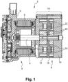
Figure 1 shows a cross-section through a gear pump according to the invention; -
Figure 2 shows a cross-section through the pre-installed pump module; -
Figure 3 shows the housing of the gear pump in a perspective view of the side facing away from the drive motor; -
Figure 4 shows the housing in a perspective view according to that inFigure 3 , wherein the housing cover is removed; -
Figure 5 shows a side view of the gear pump with the housing cover removed; -
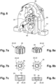
Figure 6 shows the housing part of the first pump stage in a perspective view, wherein only the drive gear is shown therein; -
Figures 7a, 7b and 7c show the gear used in the first pump stage in a perspective view, a plan view and a view in section; and -
Figures 8a, 8b and 8c show the gear used in the second pump stage in a perspective view, a plan view and a view in section. - A
gear pump 2 which is provided to provide a hydraulic oil output flow is shown inFigures 1 to 7 . This can be used, in particular in the drive train of a motor vehicle, to supply an actuator, for example to supply a clutch actuator or a gear selector, or lubrication points, for example in a gearbox or a clutch, or also in order to provide a flow of cooling oil in order, for example, to cool the friction linings of a friction clutch. - The
gear pump 2 has a drive motor 3 which is configured here as an electric motor with arotor 5. - The
rotor 5 is installed axially fixedly and non-rotatably on adrive shaft 6 which is mounted in thepump module 8 of thegear pump 2. - The
pump module 8 has ahousing 10 which in turn has ahousing part 12, a housingintermediate part 14 and ahousing cover 16. - The
pump module 8 forms, together with thedrive shaft 6 and therotor 5, a pre-installed assembly which can be installed on ahousing 9 of theelectric motor 4 in which the stator of the electric motor is also provided. - The gear pump is here configured as a two-stage pump, wherein a first stage is formed between the
housing part 12 and the housingintermediate part 14, and a second stage is formed between the housingintermediate part 14 and thehousing cover 16. The term "stage" applies to the stages of gears which are present. - Each stage has a
drive gear 20 as well as twopump gears 22. The pump is configured as a double-suction one for each stage. - The
drive gear 20 and the twopump gears 22 of each stage are configured identically; they therefore differ only in terms of their function. Thedrive gear 20 is driven by the electric motor and thepump gears 22 mesh in thedrive gear 20. - Each of the gears has a cylindrical bearing
portion 24 and a torque-transmission portion 26. These are arranged next to each other in the axial direction (see in particularFigures 7c and 8c ). Each of the portions extends here over approximately 50% of the axial length of thegear - The
bearing portion 24 is configured as a cylindrical protrusion. The torque-transmission portion 26 has, in contrast, a cross-sectional shape which differs from a circular shape. In the exemplary embodiment shown, the torque-transmission portion 26 has in cross-section the shape of a slot with rounded end sides (see in particularFigures 7b and 8b ). - The
bearing section 24 has a larger cross-section than the torque-transmission portion 26 such that, viewed from the side of thebearing portion 24, anaxial abutment shoulder 30 is formed (see in particularFigures 7c and 8c ). - The
drive shaft 6 has a torque-transmission region 32 which is configured with a cross-sectional shape adapted to the torque-transmission portion 26. Thedrive gears 20 are arranged on the torque-transmission region 32 (see in particularFigure 2 ). The torque-transmission portion 26 is coupled to the torque-transmission region 32 such that thedrive gears 20 are co-rotated when thedrive shaft 6 is set in rotation. The bearingportion 24 of the drive gears 20 here has no function. - The
drive shaft 6 is fixed in the axial direction inside thehousing 10. For this purpose, a bearing collar in the form of a retainingring 34 is provided which engages in a groove in thedrive shaft 6. The retaining ring 34 (see in particularFigure 2 ) here lies in a depression in the housingintermediate part 14 on the side facing the first stage of the gear pump. Axial stresses on thedrive shaft 6 are thus absorbed in one direction directly in the housingintermediate part 14 and in the other direction via thedrive gear 20 of the first pump stage of thehousing part 12. - The
drive shaft 6 is mounted in thehousing 10 by means of two bearingregions bearing region 36 is configured on the side of therotor 5 with a large external diameter and thebearing region 38 is configured on the side of thehousing cover 16 with a small diameter. The torque-transmission region 32, the diameter of which is smaller than the diameter of thebearing region 36 but larger than the diameter of thebearing region 38, lies between them. - The pump gears 22 are mounted in the
housing 10 by means of the bearingportion 24 which is received on a bearingstructure 40. The bearingstructure 40 is in each case designed integrally with one of the housing parts and designed so that it complements the bearingportion 24 in thecorresponding pump gear 22. - For the first pump stage, the bearing
structure 40 is configured as a cylindrical protrusion which is configured integrally with thehousing part 12. - For the second pump stage, the bearing
structure 40 is configured as a cylindrical protrusion which is configured integrally with the housingintermediate part 14. - As can be seen in particular in
Figure 2 , the pump gears 22 sit with their bearingportion 24 on the bearingstructure 40, whilst the torque-transmission portion 26 here has no function. - Because of the structure of the different components of the gear pump, the latter can be installed particularly simply.
- In a first step, the
rotor 5 is fastened on thedrive shaft 6. For example, therotor 5 can be moulded directly onto thedrive shaft 6. - The
housing part 12 is then pushed onto thedrive shaft 6 and the pump gears 22 can be placed into thehousing part 12 onto the bearingstructures 40. Thedrive gear 20 is also installed on thedrive shaft 6. In the next step, the retainingring 34 is attached and the housingintermediate part 14 is installed. Thedrive gear 20 and the pump gears 22 of the second pump stage are in turn installed therein. The housing is then closed by means of thehousing cover 16. - It can be seen that the installation takes place in one direction, for example from left to right with reference to
Figure 2 .
Claims (15)
- Gear pump (2), in particular for a hydraulic unit in a drive train of a motor vehicle, with a housing (10) which consists of multiple housing parts (12, 14, 16), with a drive gear (20) and with a pump gear (22), which are arranged inside the housing (10), characterized in that the pump gear (22) is mounted on a bearing structure (40) designed integrally with one of the housing parts (12, 14, 16).
- Gear pump (2) according to claim 1, characterized in that the bearing structure (40) is a cylindrical protrusion.
- Gear pump (2) according to claim 1 or claim 2, characterized in that the pump is a single-stage pump and the pump gear (22) is supported axially between a housing part (12) and a housing cover (16).
- Gear pump (2) according to claim 1 or claim 2, characterized in that the pump is a two-stage pump in which the pump gear (22) of the first stage is arranged between a housing part (12) and a housing intermediate part (14), and the pump gear (22) of the second stage is supported axially between the housing intermediate part (14) and a housing cover (16).
- Gear pump (2) according to claim 4, characterized in that the two stages differ in terms of their axial dimensions.
- Gear pump (2) according to one of the preceding claims, characterized in that two pump gears (22) mesh in the drive gear (20).
- Gear pump (2) according to one of the preceding claims, characterized in that the drive gear (20) and the pump gear (22) are configured identically.
- Gear pump (2) according to claim 7, characterized in that the drive gear (20) and the pump gear (22) have a cylindrical bearing portion (24) and a torque-transmission portion (26) which has a cross-sectional shape which differs from a circular shape.
- Gear pump (2) according to claim 8, characterized in that the torque-transmission portion (26) has in cross-section the shape of a slot with rounded end sides.
- Gear pump (2) according to claim 8 or claim 9, characterized in that the bearing portion (24) has at least partially a larger radius than the torque-transmission portion (26).
- Gear pump (2) according to one of the preceding claims, characterized in that a drive shaft (6) is provided which is connected non-rotatably to the drive gear (20), wherein the drive shaft (6) is fixed in the axial direction in interaction with the drive gear (20).
- Gear pump (2) according to claim 11, characterized in that the drive shaft (6) has a bearing collar (34) which is arranged between a housing part (12, 14, 16) and the drive gear (20).
- Gear pump (2) according to claim 12, characterized in that the bearing collar (34) is a retaining ring which is accommodated in a groove of the drive shaft (6).
- Gear pump (2) according to one of claims 11 to 13, characterized in that the drive shaft (6) has a torque-transmission region (32) which is arranged between two bearing regions (36, 38), wherein a first one of the bearing regions (36) has a larger external diameter than the torque-transmission region (32), and the second bearing region (38) has a smaller diameter than the torque-transmission region (32).
- Gear pump (2) according to one of claims 11 to 14, characterized in that a rotor (5) of a drive motor (4) is attached axially fixedly and non-rotatably on the drive shaft (6), wherein the first bearing region (36) is arranged between the rotor (5) and the torque-transmission region (32).
Applications Claiming Priority (1)
| Application Number | Priority Date | Filing Date | Title |
|---|---|---|---|
| DE102023105779.0A DE102023105779A1 (en) | 2023-03-08 | 2023-03-08 | Gear pump |
Publications (1)
| Publication Number | Publication Date |
|---|---|
| EP4428370A1 true EP4428370A1 (en) | 2024-09-11 |
Family
ID=90362317
Family Applications (1)
| Application Number | Title | Priority Date | Filing Date |
|---|---|---|---|
| EP24161813.1A Pending EP4428370A1 (en) | 2023-03-08 | 2024-03-06 | Gear pump |
Country Status (4)
| Country | Link |
|---|---|
| US (1) | US12378958B2 (en) |
| EP (1) | EP4428370A1 (en) |
| CN (1) | CN118622693A (en) |
| DE (1) | DE102023105779A1 (en) |
Citations (9)
| Publication number | Priority date | Publication date | Assignee | Title |
|---|---|---|---|---|
| US3692432A (en) * | 1970-12-22 | 1972-09-19 | Ford Motor Co | Two-stage positive displacement pump |
| EP0831232B1 (en) * | 1996-09-19 | 2003-03-05 | Robert Bosch Gmbh | Gear pump |
| US7309218B1 (en) * | 2004-11-10 | 2007-12-18 | Graham Louis Lewis | Gear pump |
| DE102008043871A1 (en) * | 2008-11-19 | 2010-05-20 | Robert Bosch Gmbh | fuel pump |
| DE102009028449A1 (en) * | 2009-08-11 | 2011-02-17 | Robert Bosch Gmbh | Toothed wheel pump, particularly fuel pump, has two toothed wheels, which are arranged and combed together in housing, where fuel of suction area is conveyed to pressure area |
| EP2252795B1 (en) * | 2008-03-17 | 2016-07-13 | Robert Bosch GmbH | Fuel pump |
| US10323636B2 (en) * | 2014-03-21 | 2019-06-18 | Circor Pumps North America, Llc | Gear pump with end plates or bearings having spiral grooves |
| EP3987158A1 (en) * | 2019-06-18 | 2022-04-27 | Vitesco Technologies GmbH | Pump stage assembly, external gear pump, use of a pump stage assembly and vehicle transmission |
| DE102021116160A1 (en) * | 2021-06-22 | 2022-12-22 | Fte Automotive Gmbh | Gear pump and prime mover |
Family Cites Families (6)
| Publication number | Priority date | Publication date | Assignee | Title |
|---|---|---|---|---|
| DE19615725C2 (en) * | 1996-04-20 | 1999-04-08 | Haldex Barnes Gmbh | Gear pump |
| DE102009051443A1 (en) * | 2009-10-30 | 2011-05-05 | Storz Endoskop Produktions Gmbh | Medical toothed wheel pump for use in device for sucking and rinsing of e.g. blood during laparoscopic analysis, has revolving toothed wheel attached to support, and another revolving toothed wheel attached to another support |
| DE102009047709A1 (en) * | 2009-12-09 | 2011-06-16 | Robert Bosch Gmbh | Geared pump i.e. fuel pump, of fuel system in common rail injection system of internal-combustion engine in motor vehicle, has drive element for transferring rotating movement of shaft to gear wheel and exhibiting polygonal profile |
| DE102010038893A1 (en) * | 2010-08-04 | 2012-02-09 | Robert Bosch Gmbh | Fuel pump for supplying fuel in fuel injection system, has drive wheel that is propelled by drive shaft, where drive wheel is mounted on bearing pin by friction bearing |
| CN104712554A (en) * | 2015-04-01 | 2015-06-17 | 山东大学 | Mini-type pump based on Logix gears |
| JP7017028B2 (en) * | 2017-05-01 | 2022-02-08 | 株式会社ジェイテクト | Circumscribed gear pump |
-
2023
- 2023-03-08 DE DE102023105779.0A patent/DE102023105779A1/en active Pending
-
2024
- 2024-03-05 US US18/595,525 patent/US12378958B2/en active Active
- 2024-03-06 CN CN202410253989.0A patent/CN118622693A/en active Pending
- 2024-03-06 EP EP24161813.1A patent/EP4428370A1/en active Pending
Patent Citations (9)
| Publication number | Priority date | Publication date | Assignee | Title |
|---|---|---|---|---|
| US3692432A (en) * | 1970-12-22 | 1972-09-19 | Ford Motor Co | Two-stage positive displacement pump |
| EP0831232B1 (en) * | 1996-09-19 | 2003-03-05 | Robert Bosch Gmbh | Gear pump |
| US7309218B1 (en) * | 2004-11-10 | 2007-12-18 | Graham Louis Lewis | Gear pump |
| EP2252795B1 (en) * | 2008-03-17 | 2016-07-13 | Robert Bosch GmbH | Fuel pump |
| DE102008043871A1 (en) * | 2008-11-19 | 2010-05-20 | Robert Bosch Gmbh | fuel pump |
| DE102009028449A1 (en) * | 2009-08-11 | 2011-02-17 | Robert Bosch Gmbh | Toothed wheel pump, particularly fuel pump, has two toothed wheels, which are arranged and combed together in housing, where fuel of suction area is conveyed to pressure area |
| US10323636B2 (en) * | 2014-03-21 | 2019-06-18 | Circor Pumps North America, Llc | Gear pump with end plates or bearings having spiral grooves |
| EP3987158A1 (en) * | 2019-06-18 | 2022-04-27 | Vitesco Technologies GmbH | Pump stage assembly, external gear pump, use of a pump stage assembly and vehicle transmission |
| DE102021116160A1 (en) * | 2021-06-22 | 2022-12-22 | Fte Automotive Gmbh | Gear pump and prime mover |
Also Published As
| Publication number | Publication date |
|---|---|
| US20240301877A1 (en) | 2024-09-12 |
| DE102023105779A1 (en) | 2024-09-12 |
| CN118622693A (en) | 2024-09-10 |
| US12378958B2 (en) | 2025-08-05 |
Similar Documents
| Publication | Publication Date | Title |
|---|---|---|
| EP3608140B2 (en) | Integrated electric drive powertrain | |
| US10876596B1 (en) | Electric motor with compound planetary gear drive | |
| CN102297130B (en) | High efficiency fixed displacement vane pump | |
| US20140286801A1 (en) | Pumping device for pumping oil from a storage container to a transmission system of a motor vehicle | |
| DE112015000054B4 (en) | Electric oil pump | |
| US12305638B2 (en) | Gear pump and drive machine | |
| US12162449B2 (en) | Electromechanical brake pressure generator including spindle drive unit, braking system | |
| KR102144202B1 (en) | Conveying device for conveying oil | |
| US6158326A (en) | Unit consisting of an electric motor and of a working machine driven thereby | |
| EP1553332B1 (en) | Drive axle assembly | |
| EP3522342A1 (en) | Gear driving device for automotive movable parts | |
| JP2016522353A (en) | Pumping device that pumps oil from the storage container to the transmission of the car | |
| EP4428370A1 (en) | Gear pump | |
| US20050152790A1 (en) | Pumping unit | |
| JP2007506044A (en) | Auxiliary unit transmission for vehicle engine, and auxiliary unit provided with pulley capable of coupling and releasing clutch | |
| KR102419493B1 (en) | fluid pumping system | |
| US20050169773A1 (en) | Oil pump for an automatic transmission of a motor vehicle | |
| KR20170018090A (en) | Transmission arrangement for a vehicle | |
| US20170077784A1 (en) | Auxiliary drive device | |
| US20070274848A1 (en) | Motor-pump assembly | |
| US11506208B2 (en) | Assembly for the hybrid propulsion of a motor vehicle pump | |
| EP2140141B1 (en) | Dual stage pump having intermittent mid-shaft load supports | |
| CN111734808B (en) | Oil return pump of automatic transmission | |
| CN113169621A (en) | Electric motor | |
| CN114207323B (en) | Differential cover of the planetary carrier fastened by crimping |
Legal Events
| Date | Code | Title | Description |
|---|---|---|---|
| PUAI | Public reference made under article 153(3) epc to a published international application that has entered the european phase |
Free format text: ORIGINAL CODE: 0009012 |
|
| STAA | Information on the status of an ep patent application or granted ep patent |
Free format text: STATUS: THE APPLICATION HAS BEEN PUBLISHED |
|
| AK | Designated contracting states |
Kind code of ref document: A1 Designated state(s): AL AT BE BG CH CY CZ DE DK EE ES FI FR GB GR HR HU IE IS IT LI LT LU LV MC ME MK MT NL NO PL PT RO RS SE SI SK SM TR |
|
| STAA | Information on the status of an ep patent application or granted ep patent |
Free format text: STATUS: REQUEST FOR EXAMINATION WAS MADE |
|
| 17P | Request for examination filed |
Effective date: 20250304 |
|
| STAA | Information on the status of an ep patent application or granted ep patent |
Free format text: STATUS: EXAMINATION IS IN PROGRESS |
|
| 17Q | First examination report despatched |
Effective date: 20250626 |
|
| GRAP | Despatch of communication of intention to grant a patent |
Free format text: ORIGINAL CODE: EPIDOSNIGR1 |
|
| STAA | Information on the status of an ep patent application or granted ep patent |
Free format text: STATUS: GRANT OF PATENT IS INTENDED |