EP4428340A1 - Method for manufacturing a composite bladed disk or rotor - Google Patents
Method for manufacturing a composite bladed disk or rotor Download PDFInfo
- Publication number
- EP4428340A1 EP4428340A1 EP24156979.7A EP24156979A EP4428340A1 EP 4428340 A1 EP4428340 A1 EP 4428340A1 EP 24156979 A EP24156979 A EP 24156979A EP 4428340 A1 EP4428340 A1 EP 4428340A1
- Authority
- EP
- European Patent Office
- Prior art keywords
- pair
- adjacent segments
- slots
- component
- finger joint
- Prior art date
- Legal status (The legal status is an assumption and is not a legal conclusion. Google has not performed a legal analysis and makes no representation as to the accuracy of the status listed.)
- Granted
Links
Images



Classifications
-
- F—MECHANICAL ENGINEERING; LIGHTING; HEATING; WEAPONS; BLASTING
- F01—MACHINES OR ENGINES IN GENERAL; ENGINE PLANTS IN GENERAL; STEAM ENGINES
- F01D—NON-POSITIVE DISPLACEMENT MACHINES OR ENGINES, e.g. STEAM TURBINES
- F01D5/00—Blades; Blade-carrying members; Heating, heat-insulating, cooling or antivibration means on the blades or the members
- F01D5/12—Blades
- F01D5/28—Selecting particular materials; Particular measures relating thereto; Measures against erosion or corrosion
- F01D5/282—Selecting composite materials, e.g. blades with reinforcing filaments
-
- F—MECHANICAL ENGINEERING; LIGHTING; HEATING; WEAPONS; BLASTING
- F01—MACHINES OR ENGINES IN GENERAL; ENGINE PLANTS IN GENERAL; STEAM ENGINES
- F01D—NON-POSITIVE DISPLACEMENT MACHINES OR ENGINES, e.g. STEAM TURBINES
- F01D5/00—Blades; Blade-carrying members; Heating, heat-insulating, cooling or antivibration means on the blades or the members
- F01D5/30—Fixing blades to rotors; Blade roots ; Blade spacers
- F01D5/3007—Fixing blades to rotors; Blade roots ; Blade spacers of axial insertion type
-
- F—MECHANICAL ENGINEERING; LIGHTING; HEATING; WEAPONS; BLASTING
- F01—MACHINES OR ENGINES IN GENERAL; ENGINE PLANTS IN GENERAL; STEAM ENGINES
- F01D—NON-POSITIVE DISPLACEMENT MACHINES OR ENGINES, e.g. STEAM TURBINES
- F01D5/00—Blades; Blade-carrying members; Heating, heat-insulating, cooling or antivibration means on the blades or the members
- F01D5/34—Rotor-blade aggregates of unitary construction, e.g. formed of sheet laminae
-
- F—MECHANICAL ENGINEERING; LIGHTING; HEATING; WEAPONS; BLASTING
- F05—INDEXING SCHEMES RELATING TO ENGINES OR PUMPS IN VARIOUS SUBCLASSES OF CLASSES F01-F04
- F05D—INDEXING SCHEME FOR ASPECTS RELATING TO NON-POSITIVE-DISPLACEMENT MACHINES OR ENGINES, GAS-TURBINES OR JET-PROPULSION PLANTS
- F05D2230/00—Manufacture
- F05D2230/20—Manufacture essentially without removing material
- F05D2230/23—Manufacture essentially without removing material by permanently joining parts together
-
- F—MECHANICAL ENGINEERING; LIGHTING; HEATING; WEAPONS; BLASTING
- F05—INDEXING SCHEMES RELATING TO ENGINES OR PUMPS IN VARIOUS SUBCLASSES OF CLASSES F01-F04
- F05D—INDEXING SCHEME FOR ASPECTS RELATING TO NON-POSITIVE-DISPLACEMENT MACHINES OR ENGINES, GAS-TURBINES OR JET-PROPULSION PLANTS
- F05D2230/00—Manufacture
- F05D2230/50—Building or constructing in particular ways
-
- F—MECHANICAL ENGINEERING; LIGHTING; HEATING; WEAPONS; BLASTING
- F05—INDEXING SCHEMES RELATING TO ENGINES OR PUMPS IN VARIOUS SUBCLASSES OF CLASSES F01-F04
- F05D—INDEXING SCHEME FOR ASPECTS RELATING TO NON-POSITIVE-DISPLACEMENT MACHINES OR ENGINES, GAS-TURBINES OR JET-PROPULSION PLANTS
- F05D2230/00—Manufacture
- F05D2230/90—Coating; Surface treatment
-
- F—MECHANICAL ENGINEERING; LIGHTING; HEATING; WEAPONS; BLASTING
- F05—INDEXING SCHEMES RELATING TO ENGINES OR PUMPS IN VARIOUS SUBCLASSES OF CLASSES F01-F04
- F05D—INDEXING SCHEME FOR ASPECTS RELATING TO NON-POSITIVE-DISPLACEMENT MACHINES OR ENGINES, GAS-TURBINES OR JET-PROPULSION PLANTS
- F05D2300/00—Materials; Properties thereof
- F05D2300/60—Properties or characteristics given to material by treatment or manufacturing
- F05D2300/603—Composites; e.g. fibre-reinforced
Definitions
- the present disclosure relates generally to a method for manufacturing a composite bladed disk or rotor for a gas turbine engine.
- a gas turbine engine typically includes, in axial series, a compressor, combustion equipment, and a turbine that drives the compressor. During operation, air is compressed by the compressor, the compressed air is mixed with fuel and combusted by the combustion equipment, and the resulting combustion products are expelled through the turbine.
- the compressor may include a bladed disk or rotor including a disk and a plurality of blades mounted on the disk. It may be advantageous to manufacture the disk from composite materials as opposed to metals, for example, to reduce the weight of the bladed disk or rotor.
- conventional manufacturing techniques may require complex tooling and moulding processes for manufacturing the disk from composite materials as well as complicated assembly processes for mounting the plurality of blades on the disk. Therefore, conventional manufacturing techniques may be complicated and uneconomical.
- a method for manufacturing a composite bladed disk or rotor for a gas turbine engine includes forming a moulded component from at least one composite material.
- the moulded component is axisymmetric about a component axis.
- the method further includes segmenting the moulded component into a plurality of segments disposed adjacent to each other. Each pair of adjacent segments from the plurality of segments includes a pair of surfaces that is formed during segmentation of the moulded component.
- the method further includes providing, via computerised numerical control (CNC) machining, complementary finger joint profiles on the pair of surfaces of the each pair of adjacent segments.
- the method further includes providing a plurality of slots on at least one of the pair of surfaces of the each pair of adjacent segments.
- Each of the plurality of slots at least partially extends along the component axis and perpendicularly to the component axis.
- the method further includes positioning a plurality of blades partially within the plurality of slots.
- the method further includes mating the complementary finger joint profiles provided on the pair of surfaces of the each pair of adjacent segments.
- the method further includes joining the each pair of adjacent segments to each other, such that the plurality of blades is retained within the plurality of slots.
- the method of the present disclosure may facilitate mounting of the plurality of blades to the moulded component (which may correspond to a rotor disk). Specifically, mounting of the plurality of blades to the moulded component may be facilitated by providing the plurality of slots, positioning the plurality of blades partially within the plurality of slots, and joining the each pair of adjacent segments to each other. Each of the plurality of blades may consequently be permanently trapped or retained within a corresponding slot from the plurality of slots.
- the complementary finger joint profiles may allow providing a reliable structural joint between the each pair of adjacent segments, which may be capable of withstanding loads during operation of the gas turbine engine.
- the method may allow tailoring the complementary finger joint profiles to suit the duty/load case of the structural joint. That is, the design and size of the complementary finger joint profiles may be modified according to the performance requirements. This may ensure that segmenting the moulded component into the plurality of segments and joining the plurality of segments may not negatively affect the load bearing capacity of the moulded component.
- the method may further allow the use of blades made from composite materials as well as metals and having different retention features (such as dovetail features and fir-tree features).
- the method may also allow the use of various different composite materials as well as hybrid assemblies containing mixed classes of materials to manufacture the composite bladed disk or rotor, based on desired application requirements.
- the method may therefore be simple, economical, allow flexibility in material choice as per application requirements, and may be carried out without the need to use complex tooling and moulding processes.
- forming the moulded component includes depositing the at least one composite material on a mandrel.
- the method further includes removing the mandrel from the moulded component prior to segmenting the moulded component.
- the moulded component may therefore be economically formed using, for example, filament winding.
- the moulded component forms a plurality of stages of the composite bladed disk or rotor.
- the plurality of blades of the each pair of adjacent segments includes a corresponding stage from the plurality of stages.
- the at least one composite material includes a plurality of composite materials that differ from each other.
- Each of the plurality of segments includes a corresponding composite material from the plurality of composite materials.
- the method may allow forming the plurality of segments with composite materials having different properties (for example, thermal capabilities). Therefore, it may be possible to select composite materials based on the operational thermal environment of a segment. For example, an axially downstream segment may be made from a composite material that has a greater thermal capacity than that of an axially upstream segment.
- each of the complementary finger joint profiles includes a plurality of circumferential fingers concentrically spaced apart from each other with respect to the component axis.
- each of the complementary finger joint profiles comprises a plurality of fingers extending perpendicularly to the component axis.
- the method may allow flexibility in designing the complementary finger joint profiles based on the desired application requirements.
- each adjacent segment of the each pair of adjacent segments has a section thickness defined perpendicularly to the component axis.
- Each of the complementary finger joint profiles includes a plurality of fingers. Each of the plurality of fingers has a length defined along the component axis. The length is from 0.5 times to 2 times of the section thickness.
- the aforementioned length of the plurality of fingers may ensure that a reliable structural joint can be formed between the each pair of adjacent segments when the each pair of adjacent segments are joined.
- each of the plurality of slots is a dovetail slot.
- the dovetail slot of each of the plurality of slots may receive a blade having a dovetail retention feature.
- the method further includes applying a joint adhesive layer on at least one of the complementary finger joint profiles prior to mating the complementary finger joint profiles of the each pair of adjacent segments.
- the joint adhesive layer may improve joining of the each pair of adjacent segments and may improve the robustness of the joint formed between the each pair of adjacent segments.
- joining the each pair of adjacent segments includes curing the joint adhesive layer.
- the joint adhesive layer may include an adhesive that can be cured to provide a strong, permanent, and robust bond between the each pair of adjacent segments.
- An example of such adhesive includes an epoxy adhesive.
- the method further includes applying a slot adhesive layer in each of the plurality of slots prior to positioning the plurality of blades partially within the plurality of slots, such that each of the plurality of blades is bonded to at least one of the each pair of adjacent segments.
- the slot adhesive layer may ensure retention of the plurality of blades with the plurality of slots.
- the method further includes providing an alignment feature on the each pair of adjacent segments.
- the method further includes aligning the each pair of adjacent segments with each other based on the alignment feature prior to mating the complementary finger joint profiles of the each pair of adjacent segments.
- the alignment feature may facilitate aligning of the each pair of adjacent segments with each other, and as a result may improve the robustness of the joint formed between the each pair of adjacent segments.
- the method further includes coupling the moulded component to a drive shaft of the gas turbine engine.
- the drive shaft of the gas turbine engine may drive the composite bladed disk or rotor.
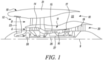
- FIG. 1 illustrates a gas turbine engine 10 having a principal rotational axis 9.
- the engine 10 comprises an air intake 12 and a propulsive fan 23 that generates two airflows: a core airflow
- the gas turbine engine 10 comprises a core 11 that receives the core airflow A.
- the engine core 11 comprises, in axial flow series, a low pressure compressor 14, a high pressure compressor 15, combustion equipment 16, a high pressure turbine 17, a low pressure turbine 19, and a core exhaust nozzle 20.
- a nacelle 21 surrounds the gas turbine engine 10 and defines a bypass duct 22 and a bypass exhaust nozzle 18.
- the bypass airflow B flows through the bypass duct 22.
- the fan 23 is attached to and driven by the low pressure turbine 19 via a shaft 26 and an epicyclic gearbox 30.
- the core airflow A is accelerated and compressed by the low pressure compressor 14 and directed into the high pressure compressor 15 where further compression takes place.
- the compressed air exhausted from the high pressure compressor 15 is directed into the combustion equipment 16 where it is mixed with fuel and the mixture is combusted.
- the resultant hot combustion products then expand through, and thereby drive, the high pressure and low pressure turbines 17, 19 before being exhausted through the core exhaust nozzle 20 to provide some propulsive thrust.
- the high pressure turbine 17 drives the high pressure compressor 15 by a suitable interconnecting shaft 27.
- the fan 23 generally provides the majority of the propulsive thrust.
- the epicyclic gearbox 30 is a reduction gearbox.
- low pressure turbine and “low pressure compressor” as used herein may be taken to mean the lowest pressure turbine stages and lowest pressure compressor stages (i.e., not including the fan 23) respectively and/or the turbine and compressor stages that are connected together by the interconnecting shaft 26 with the lowest rotational speed in the engine (i.e., not including the gearbox output shaft that drives the fan 23).
- the "low pressure turbine” and “low pressure compressor” referred to herein may alternatively be known as the “intermediate pressure turbine” and “intermediate pressure compressor”. Where such alternative nomenclature is used, the fan 23 may be referred to as a first, or lowest pressure, compression stage.
- gas turbine engines to which the present disclosure may be applied may have alternative configurations.
- such engines may have an alternative number of compressors and/or turbines and/or an alternative number of interconnecting shafts.
- the gas turbine engine 10 shown in FIG. 1 has a split flow nozzle 18, 20 meaning that the flow through the bypass duct 22 has its own nozzle 18 that is separate to and radially outside the core exhaust nozzle 20.
- this is not limiting, and any aspect of the present disclosure may also apply to engines in which the flow through the bypass duct 22 and the flow through the core 11 are mixed, or combined, before (or upstream of) a single nozzle, which may be referred to as a mixed flow nozzle.
- One or both nozzles may have a fixed or variable area.
- the described example relates to a turbofan engine, the disclosure may apply, for example, to any type of gas turbine engine, such as an open rotor (in which the fan stage is not surrounded by a nacelle) or turboprop engine, for example.
- the gas turbine engine 10 may not comprise a gearbox 30.
- the geometry of the gas turbine engine 10, and components thereof, is defined by a conventional axis system, comprising an axial direction (which is aligned with the rotational axis 9), a radial direction (in the bottom-to-top direction in FIG. 1 ), and a circumferential direction (perpendicular to the page in the FIG. 1 view).
- the axial, radial, and circumferential directions are mutually perpendicular.
- first and second are used as identifiers. Therefore, such terms should not be construed as limiting of this disclosure.
- the terms “first” and “second” when used in conjunction with a feature or an element can be interchanged throughout the embodiments of this disclosure.
- FIG. 2 shows a flowchart depicting various steps of a method 100 for manufacturing a composite bladed disk or rotor for a gas turbine engine, such as the gas turbine engine 10 of FIG. 1 , in accordance with an embodiment of the present disclosure.
- the composite bladed disk or rotor may be included in, for example, the low pressure compressor 14 or the high pressure compressor 15 of FIG. 1 .
- the method 100 will be described with further reference to FIGS. 3A to 9B , which schematically depict the various steps of the method 100.
- the method 100 includes forming a moulded component from at least one composite material.
- composite material refers to a material including an additive material and a matrix material that supports the additive material.
- the additive material may be embedded in the matrix material.
- the matrix material may be, for example, organic/polymeric and/or ceramic.
- composite materials may include organic/polymer matrix composites and/or ceramic matrix composites.
- the matrix material may be thermosetting or thermoplastic.
- the additive material may be a reinforcing material.
- the additive material may include, but is not limited to, carbon, glass, graphite, aramid, and organic fibre of any length, size, and orientation.
- the moulded component is axisymmetric about a component axis.
- the moulded component may therefore be a rotationally symmetric component.
- the moulded component may correspond to a rotor disk (also referred to as “rotor drum” and “rotor hub”).
- the method 100 may include forming a moulded component 200 from at least one composite material.
- the moulded component 200 may be axisymmetric about a component axis 205.
- the moulded component 200 may be formed using any suitable method, and the disclosure is not limited thereto.
- the moulded component 200 may be formed using automated fibre placement (AFP), filament winding, hand layup, pick and place automation, and the like.
- AFP automated fibre placement
- filament winding filament winding
- hand layup hand layup
- pick and place automation and the like.
- forming the moulded component may include depositing the at least one composite material on a mandrel.
- forming the moulded component 200 may include depositing the at least one composite material on a mandrel 201.
- the mandrel 201 is hatched in FIG. 3A for clarity purposes.
- the at least one composite material may be deposited on the mandrel 201 from a prepreg tape.
- the prepreg tape may be a thermoplastic or a thermosetting composite prepreg tape.
- the moulded component 200 once formed, may be removed from the mandrel 201, as shown in FIG. 3B .
- the mandrel 201 may be a filament winding mandrel that defines an inner surface of the moulded component 200, and the moulded component 200 may be formed using a filament winding process.
- the moulded component 200 may be formed by employing a wet filament winding process using dry carbon fibre and a liquid matrix resin.
- the method 100 further includes segmenting the moulded component into a plurality of segments disposed adjacent to each other.
- Each pair of adjacent segments from the plurality of segments includes a pair of surfaces that is formed during segmentation of the moulded component.
- the method 100 may include segmenting the moulded component 200 into a plurality of segments 210 disposed adjacent to each other.
- the moulded component 200 is segmented into a first segment 210A, a second segment 210B, and a third segment 210C.
- the plurality of segments 210 includes the first segment 210A, the second segment 210B, and the third segment 210C.
- Each pair of adjacent segments 211 from the plurality of segments 210 includes a pair of surfaces 212 that is formed during segmentation of the moulded component 200.
- the reference character "211" is used to generally indicate each pair of adjacent segments from the plurality of segments 210.
- the plurality of segments 210 includes a pair of adjacent segments 211 that includes the first segment 210A and the second segment 210B, and another pair of adjacent segments 211 that includes the second segment 210B and the third segment 210C.
- the each pair of adjacent segments 211 includes the pair of surfaces 212 that is formed during segmentation of the moulded component 200.
- the at least one composite material may include a plurality of composite materials that differ from each other.
- Each of the plurality of segments may include a corresponding composite material from the plurality of composite materials.
- the first segment 210A may include a first composite material
- the second segment 210B may include a second composite material
- the third segment 210C may include a third composite material.
- the first segment 210A may be formed from the first composite material
- the second segment 210B may be formed from the second composite material
- the third segment 210C may be formed from the third composite material.
- the first, second, and third composite materials may differ from each other.
- the first, second, and third composite materials may have different thermal capabilities.
- the method 100 may further include removing the mandrel from the moulded component prior to segmenting the moulded component.
- the method 100 may include removing the mandrel 201 (shown in FIG. 3A ) from the moulded component 200 prior to segmenting the moulded component 200.
- FIG. 3B shows the moulded component 200 with the mandrel 201 removed therefrom.
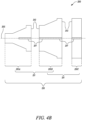
- the method 100 may further include providing an alignment feature on the each pair of adjacent segments.
- the method 100 may include providing an alignment feature 217 on the each pair of adjacent segments 211.
- the alignment feature 217 may include indicia, markings, and the like to facilitate aligning the each pair of adjacent segments 211.
- the alignment feature 217 may be provided on the moulded component 200 prior to segmenting the moulded component 200 into the plurality of segments 210.
- the alignment feature 217 may extend at least partially along the component axis 205.
- the alignment feature 217 may be aligned with the component axis 205.
- the method 100 further includes providing, via computerised numerical control (CNC) machining, complementary finger joint profiles on the pair of surfaces of the each pair of adjacent segments.
- CNC computerised numerical control
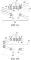
- the method 100 may include providing, via CNC machining, complementary finger joint profiles 215 on the pair of surfaces 212 of the each pair of adjacent segments 211.
- the complementary finger joint profiles 215 may be machined by a cutting tool 218 that is part of a CNC machine.
- the complementary finger joint profiles 215 may be machined by, for example, turning, milling, and/or grinding.
- Each of the complementary finger joint profiles may include a plurality of fingers.
- each of the complementary finger joint profiles 215 may include a plurality of fingers 216.
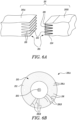
- FIG. 6A shows a perspective view of portions of the first segment 210A and the second segment 210B and exemplary complementary finger joint profiles 215 including the plurality of fingers 216.
- each adjacent segment of the each pair of adjacent segments may have a section thickness defined perpendicularly to the component axis. Further, each of the plurality of fingers may have a length defined along the component axis. The length may be from 0.5 times to 2 times of the section thickness.
- each adjacent segment 211 of the each pair of adjacent segments 211 may have a section thickness 213T defined perpendicularly to the component axis 205.
- each of the first segment 210A and the second segment 210B has the section thickness 213T (only indicated on the first segment 210A for illustrative purposes).
- each of the plurality of fingers 216 may have a length 216L (only indicated on the first segment 210A for illustrative purposes) defined along the component axis 205.
- the length 216L may be from 0.5 times to 2 times of the section thickness 213T.
- the length 216L may be equal to the section thickness 213T.
- the length 216L being from 0.5 times to 2 times of the section thickness 213T may increase the robustness of a joint formed by mating and joining the complementary finger joint profiles 215.
- each of the complementary finger joint profiles may include a plurality of circumferential fingers concentrically spaced apart from each other with respect to the component axis.
- each of the complementary finger joint profiles 215 may include a plurality of circumferential fingers 216A concentrically spaced apart from each other with respect to the component axis 205.
- the plurality of fingers 216 may be circumferential and concentrically spaced apart from each other with respect to the component axis 205.
- each of the complementary finger joint profiles may include a plurality of fingers extending perpendicularly to the component axis.
- each of the complementary finger joint profiles 215 may include a plurality of fingers 216B extending perpendicularly to the component axis 205.
- the plurality of fingers 216 may extend perpendicularly to the component axis 205.
- the plurality of fingers 216B may be linear or curved.
- the each pair of adjacent segments 211 may be indexed and provided with the plurality of slots 220 by, for example, by a cutting tool 219 (shown schematically in FIG. 7A ).
- each of the plurality of slots may be a dovetail slot.
- each of the plurality of slots 220 may be a dovetail slot.
- each of the plurality of slots 220 may be a fir tree slot. It may be noted that the plurality of slots 220 may have any suitable configuration to receive a plurality of aerofoils or blades therein.
- the method 100 further includes positioning a plurality of blades partially within the plurality of slots.
- the method 100 may include positioning a plurality of blades 230 partially within the plurality of slots 220.
- the plurality of blades 230 may be made from composite materials or metallic materials.
- composite blades may be manufactured by laminating composite materials and autoclave and press moulding the laminated composite materials.
- Composite blades may also be 3D woven and resin transfer moulded.
- Composite blades may also be compression moulded from short fibre reinforced composites or a combination of 'continuous' and short fibre composites.
- Composite blades may be injection moulded using short fibre composites or a combination of 'continuous' and short fibre composites.
- Metallic blades they may be cast, forged, machined from solid, additive layer manufactured, metal injection moulded and hot iso-statically pressed, or sintered.
- Each of the plurality of slots 220 may partially receive a corresponding blade 230 from the plurality of blades 230.
- Each of the plurality of blades 230 may include a retention feature (not shown) disposed adjacent to its root. The retention feature of the plurality of blades 230 may be at least partially positioned within the plurality of slots 220.
- the method 100 may further include applying a slot adhesive layer in each of the plurality of slots prior to positioning the plurality of blades partially within the plurality of slots, such that each of the plurality of blades is bonded to at least one of the each pair of adjacent segments.
- the method 100 may include applying a slot adhesive layer 222 (hatched with dots in FIG. 8A ) in each of the plurality of slots 220 prior to positioning the plurality of blades 230 partially within the plurality of slots 220.
- the slot adhesive layer 222 is only shown in one slot 220 in FIG. 8A for illustrative purposes.
- the slot adhesive layer 222 may be continuous or patterned.
- the slot adhesive layer 222 may include, for example, an epoxy adhesive.
- the slot adhesive layer 222 may include any suitable adhesive capable of bonding the plurality of blades 230 to at least one of the each pair of adjacent segments 211.
- applying the slot adhesive layer 222 in each of the plurality of slots 220 is optional and may be omitted.
- the method 100 may include providing an anti-friction coating or an anti-friction liner on each of the plurality of blades 230 or in each of the plurality of slots 220.
- the method 100 may also include providing a biasing member (not shown), such as a spring element, to maintain contact of the plurality of blades 230 against the respective plurality of slots 220.
- the method 100 further includes mating the complementary finger joint profiles provided on the pair of surfaces of the each pair of adjacent segments.
- the method 100 may include mating the complementary finger joint profiles 215 provided on the pair of surfaces 212 of the pair of adjacent segments 211.
- a press or similar tools may be employed to move the each pair of adjacent segments 211 in order to mate the complementary finger joint profiles 215.
- the method 100 may further include aligning the each pair of adjacent segments with each other based on the alignment feature prior to mating the complementary finger joint profiles of the each pair of adjacent segments.
- the method 100 may further include aligning the each pair of adjacent segments 211 with each other based on the alignment feature 217 (shown in FIG. 4A ) prior to mating the complementary finger joint profiles 215 of the each pair of adjacent segments 211.
- the method 100 may further include applying a joint adhesive layer on at least one of the complementary finger joint profiles prior to mating the complementary finger joint profiles of the each pair of adjacent segments.
- the method 100 may further include applying a joint adhesive layer 224 (hatched with dots in FIG. 6A ) on at least one of the complementary finger joint profiles 215 prior to mating the complementary finger joint profiles 215 of the each pair of adjacent segments 211.
- the joint adhesive layer 224 is applied on one of the complementary finger joint profiles 215 (specifically, the finger joint profile 215 of the second segment 110B).
- the joint adhesive layer 224 may be continuous or patterned.
- the joint adhesive layer 224 may be applied at least partially between adjacent fingers 216 from the plurality of fingers 216.
- the joint adhesive layer 224 may include, for example, an epoxy adhesive.
- the joint adhesive layer 224 may include any suitable adhesive capable of bonding the each pair of adjacent segments 211.
- the complementary finger joint profiles 215 may facilitate bonding of the each pair of adjacent segments 211.
- the method 100 further includes joining the each pair of adjacent segments to each other, such that the plurality of blades is retained within the plurality of slots.
- the method 100 may include joining the each pair of adjacent segments 211 to each other, such that the plurality of blades 230 is retained within the plurality of slots 220.
- each pair of adjacent segments 211 may be joined by heating the moulded component 200. Heat may be applied to the moulded component 200, for example, by placing the moulded component 200 in an oven.
- joining the each pair of adjacent segments may include curing the joint adhesive layer.
- joining the each pair of adjacent segments 211 may include curing the joint adhesive layer 224 (shown in FIG. 6A ).
- the joint adhesive layer 224 may be cured by application of heat.
- FIG. 9A shows a bladed disk or rotor 250 manufactured by the method 100 of FIG. 2 .
- the moulded component may form a plurality of stages of the composite bladed disk or rotor.
- the plurality of blades of the each pair of adjacent segments may include a corresponding stage from the plurality of stages.
- the moulded component 200 may form a plurality of stages 251, 252 of the composite bladed disk or rotor 250.
- the composite bladed disk or rotor 250 may be a two-stage axial compressor (having a first stage 251 and a second stage 252).
- the plurality of blades 230 of the each pair of adjacent segments 211 includes a corresponding stage 251, 252 from the plurality of stages 251, 252.
- each of the plurality of segments 210A, 210B, 210C may include a corresponding composite material from the plurality of composite materials that differ from each other.
- the thermal environment may change along the axial length (i.e., along the component axis 205) of the composite bladed disk or rotor 250.
- the method 100 may allow forming the different segments 210A, 210B, 210C with composite materials having different thermal capability based on the thermal environment.
- the third segment 210C may be made from a composite material that has a greater thermal capacity than that of the first segment 210A.
- the gas turbine engine 10 includes the bladed disk or rotor 250.
- the low pressure compressor 14 and/or the high pressure compressor 15 may include the bladed disk or rotor 250.
- the method 100 may further include coupling the moulded component 200 to a drive shaft (e.g., the interconnecting shaft 27) of the gas turbine engine 10.
- a drive shaft e.g., the interconnecting shaft 27
- the moulded component 200 may be machined to accept an insert 240.
- the insert 240 may be interference press-fitted to the moulded component 200.
- the insert 240 may be configured to accept a splined shaft (e.g., the interconnecting shaft 27) of the gas turbine engine 10, thereby allowing coupling of the moulded component 200 to the drive shaft of the gas turbine engine 10.
- the drive shaft may connect the composite bladed disk or rotor 250 to the turbine of the gas turbine engine 10.
- the method 100 may facilitate mounting of the plurality of blades 230 to the moulded component 200. Specifically, mounting of the plurality of blades 230 to the moulded component 200 may be facilitated by providing the plurality of slots 220, positioning the plurality of blades 230 partially within the plurality of slots 220, and joining the each pair of adjacent segments 211 to each other. Each of the plurality of blades 230 may consequently be permanently trapped or retained within a corresponding slot 220 from the plurality of slots 220.
- the complementary finger joint profiles 215 may allow providing a reliable structural joint between the each pair of adjacent segments 211, which may be capable of withstanding loads during operation of the gas turbine engine 10. Moreover, the method 100 may allow tailoring the complementary finger joint profiles 215 to suit the duty/load case of the structural joint. That is, the design and size of the complementary finger joint profiles 215 may be modified according to the performance requirements. This may ensure that segmenting the moulded component 200 into the plurality of segments 210 and joining the plurality of segments 210 may not negatively affect the load bearing capacity of the moulded component 200.
- the method 100 may further allow the use of blades 230 made from composite materials as well as metals and having different retention features (such as dovetail features and fir-tree features).
- the method 100 may also allow the use of various different composite materials as well as hybrid assemblies containing mixed classes of materials to manufacture the composite bladed disk or rotor 250, based on desired application requirements.
- the method 100 may therefore be simple, economical, allow flexibility in material choice as per application requirements, and may be carried out without the need to use complex tooling and moulding processes.
Landscapes
- Engineering & Computer Science (AREA)
- Mechanical Engineering (AREA)
- General Engineering & Computer Science (AREA)
- Chemical & Material Sciences (AREA)
- Materials Engineering (AREA)
- Composite Materials (AREA)
- Ceramic Engineering (AREA)
- Structures Of Non-Positive Displacement Pumps (AREA)
Abstract
Description
- The present disclosure relates generally to a method for manufacturing a composite bladed disk or rotor for a gas turbine engine.
- A gas turbine engine typically includes, in axial series, a compressor, combustion equipment, and a turbine that drives the compressor. During operation, air is compressed by the compressor, the compressed air is mixed with fuel and combusted by the combustion equipment, and the resulting combustion products are expelled through the turbine.
- The compressor may include a bladed disk or rotor including a disk and a plurality of blades mounted on the disk. It may be advantageous to manufacture the disk from composite materials as opposed to metals, for example, to reduce the weight of the bladed disk or rotor. However, conventional manufacturing techniques may require complex tooling and moulding processes for manufacturing the disk from composite materials as well as complicated assembly processes for mounting the plurality of blades on the disk. Therefore, conventional manufacturing techniques may be complicated and uneconomical.
- According to a first aspect there is provided a method for manufacturing a composite bladed disk or rotor for a gas turbine engine. The method includes forming a moulded component from at least one composite material. The moulded component is axisymmetric about a component axis. The method further includes segmenting the moulded component into a plurality of segments disposed adjacent to each other. Each pair of adjacent segments from the plurality of segments includes a pair of surfaces that is formed during segmentation of the moulded component. The method further includes providing, via computerised numerical control (CNC) machining, complementary finger joint profiles on the pair of surfaces of the each pair of adjacent segments. The method further includes providing a plurality of slots on at least one of the pair of surfaces of the each pair of adjacent segments. Each of the plurality of slots at least partially extends along the component axis and perpendicularly to the component axis. The method further includes positioning a plurality of blades partially within the plurality of slots. The method further includes mating the complementary finger joint profiles provided on the pair of surfaces of the each pair of adjacent segments. The method further includes joining the each pair of adjacent segments to each other, such that the plurality of blades is retained within the plurality of slots.
- The method of the present disclosure may facilitate mounting of the plurality of blades to the moulded component (which may correspond to a rotor disk). Specifically, mounting of the plurality of blades to the moulded component may be facilitated by providing the plurality of slots, positioning the plurality of blades partially within the plurality of slots, and joining the each pair of adjacent segments to each other. Each of the plurality of blades may consequently be permanently trapped or retained within a corresponding slot from the plurality of slots.
- Further, the complementary finger joint profiles may allow providing a reliable structural joint between the each pair of adjacent segments, which may be capable of withstanding loads during operation of the gas turbine engine. Moreover, the method may allow tailoring the complementary finger joint profiles to suit the duty/load case of the structural joint. That is, the design and size of the complementary finger joint profiles may be modified according to the performance requirements. This may ensure that segmenting the moulded component into the plurality of segments and joining the plurality of segments may not negatively affect the load bearing capacity of the moulded component.
- The method may further allow the use of blades made from composite materials as well as metals and having different retention features (such as dovetail features and fir-tree features). The method may also allow the use of various different composite materials as well as hybrid assemblies containing mixed classes of materials to manufacture the composite bladed disk or rotor, based on desired application requirements.
- The method may therefore be simple, economical, allow flexibility in material choice as per application requirements, and may be carried out without the need to use complex tooling and moulding processes.
- In some embodiments, forming the moulded component includes depositing the at least one composite material on a mandrel.
- In some embodiments, the method further includes removing the mandrel from the moulded component prior to segmenting the moulded component.
- The moulded component may therefore be economically formed using, for example, filament winding.
- In some embodiments, the moulded component forms a plurality of stages of the composite bladed disk or rotor. The plurality of blades of the each pair of adjacent segments includes a corresponding stage from the plurality of stages.
- In some embodiments, the at least one composite material includes a plurality of composite materials that differ from each other. Each of the plurality of segments includes a corresponding composite material from the plurality of composite materials.
- Advantageously, the method may allow forming the plurality of segments with composite materials having different properties (for example, thermal capabilities). Therefore, it may be possible to select composite materials based on the operational thermal environment of a segment. For example, an axially downstream segment may be made from a composite material that has a greater thermal capacity than that of an axially upstream segment.
- In some embodiments, each of the complementary finger joint profiles includes a plurality of circumferential fingers concentrically spaced apart from each other with respect to the component axis.
- In some embodiments, each of the complementary finger joint profiles comprises a plurality of fingers extending perpendicularly to the component axis.
- Thus, the method may allow flexibility in designing the complementary finger joint profiles based on the desired application requirements.
- In some embodiments, each adjacent segment of the each pair of adjacent segments has a section thickness defined perpendicularly to the component axis. Each of the complementary finger joint profiles includes a plurality of fingers. Each of the plurality of fingers has a length defined along the component axis. The length is from 0.5 times to 2 times of the section thickness.
- The aforementioned length of the plurality of fingers may ensure that a reliable structural joint can be formed between the each pair of adjacent segments when the each pair of adjacent segments are joined.
- In some embodiments, each of the plurality of slots is a dovetail slot.
- The dovetail slot of each of the plurality of slots may receive a blade having a dovetail retention feature.
- In some embodiments, the method further includes applying a joint adhesive layer on at least one of the complementary finger joint profiles prior to mating the complementary finger joint profiles of the each pair of adjacent segments.
- The joint adhesive layer may improve joining of the each pair of adjacent segments and may improve the robustness of the joint formed between the each pair of adjacent segments.
- In some embodiments, joining the each pair of adjacent segments includes curing the joint adhesive layer.
- The joint adhesive layer may include an adhesive that can be cured to provide a strong, permanent, and robust bond between the each pair of adjacent segments. An example of such adhesive includes an epoxy adhesive.
- In some embodiments, the method further includes applying a slot adhesive layer in each of the plurality of slots prior to positioning the plurality of blades partially within the plurality of slots, such that each of the plurality of blades is bonded to at least one of the each pair of adjacent segments.
- The slot adhesive layer may ensure retention of the plurality of blades with the plurality of slots.
- In some embodiments, the method further includes providing an alignment feature on the each pair of adjacent segments. The method further includes aligning the each pair of adjacent segments with each other based on the alignment feature prior to mating the complementary finger joint profiles of the each pair of adjacent segments.
- The alignment feature may facilitate aligning of the each pair of adjacent segments with each other, and as a result may improve the robustness of the joint formed between the each pair of adjacent segments.
- In some embodiments, the method further includes coupling the moulded component to a drive shaft of the gas turbine engine.
- The drive shaft of the gas turbine engine may drive the composite bladed disk or rotor.
- The skilled person will appreciate that except where mutually exclusive, a feature or parameter described in relation to any one of the above aspects may be applied to any other aspect. Furthermore, except where mutually exclusive, any feature or parameter described herein may be applied to any aspect and/or combined with any other feature or parameter described herein.
- Embodiments will now be described by way of example only, with reference to the Figures, in which:
-
FIG. 1 is a sectional side view of a gas turbine engine; -
FIG. 2 is a flowchart depicting various steps of a method for manufacturing a composite bladed disk or rotor for a gas turbine engine in accordance with an embodiment of the present disclosure; -
FIG. 3A is a schematic sectional side view of a moulded component formed on a mandrel in accordance with an embodiment of the present disclosure; -
FIG. 3B is a schematic sectional side view of the moulded component with the mandrel removed therefrom in accordance with an embodiment of the present disclosure; -
FIG. 4A is a schematic sectional side view of the moulded component after segmenting the moulded component into a plurality of segments in accordance with an embodiment of the present disclosure; -
FIG. 4B is a schematic top view of the moulded component in accordance with an embodiment of the present disclosure; -
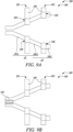
FIG. 5A is a schematic sectional side view of a pair of adjacent segments of the moulded component after providing complementary finger joint profiles in accordance with an embodiment of the present disclosure; -
FIG. 5B is a schematic sectional side view of another pair of adjacent segments of the moulded component after providing complementary finger joint profiles in accordance with an embodiment of the present disclosure; -
FIG. 6A is a schematic perspective view partially showing a pair of adjacent segments and complementary finger joint profiles in accordance with an embodiment of the present disclosure; -
FIG. 6B is a schematic sectional view of a segment of the moulded component taken along line 1-1 ofFIG. 5A and showing an exemplary finger joint profile in accordance with an embodiment of the present disclosure; -
FIG. 7A is a schematic sectional side view of the moulded component after providing a plurality of slots on a pair of surfaces of the pair of adjacent segments of the moulded component in accordance with an embodiment of the present disclosure; -
FIG. 7B is a schematic sectional view of a segment of the moulded component taken along line 2-2 ofFIG. 7A in accordance with an embodiment of the present disclosure; -
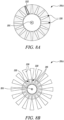
FIG. 8A is a schematic sectional view of the segment ofFIG. 7B with a slot adhesive layer applied in accordance with an embodiment of the present disclosure; -
FIG. 8B is a schematic sectional view of the segment ofFIG. 7B with a plurality of blades partially positioned partially within a plurality of slots in accordance with an embodiment of the present disclosure; -
FIG. 9A is a schematic sectional side view of a composite bladed disk or rotor in accordance with an embodiment of the present disclosure; and -
FIG. 9B is a schematic sectional side view of the composite bladed disk or rotor ofFIG. 9A machined and including an insert in accordance with an embodiment of the present disclosure. - The following table lists the reference numerals used in the drawings with the features to which they refer:
Ref no. Feature FIG. A Core airflow 1 B Bypass airflow 1 9 Axis 1 10 Gas turbine engine 1 11 Core 1 12 Air intake 1 14 Low pressure compressor 1 15 High pressure compressor 1 16 Combustion equipment 1 17 High pressure turbine 1 18 Bypass exhaust nozzle 1 19 Low pressure turbine 1 20 Core exhaust nozzle 1 21 Nacelle 1 22 Bypass duct 1 23 Propulsive fan 1 26 Shaft 1 27 Interconnecting shaft 1 30 Epicyclic gearbox 1 100 Method 2 110 Step 2 120 Step 2 130 Step 2 140 Step 2 150 Step 2 160 Step 2 170 Step 2 200 Moulded component 3A 3B 4A 4B 9A 9B 201 Mandrel 3A 205 Component axis 3A 3B 4A 4B 5A 5B 6B 7B 8A 8B 210 Segments 4A 4B 210A First segment 4A 4B 5A 6A 6B 7A 7B 8A 8B 9A 210B Second segment 4A 4B 5A 5B 6A 7A 9A 210C Third segment 4A 4B 5B 7A 9A 211 Pair of adjacent segments 4A 4B 5A 5B 6A 7A 9A 212 Pair of surfaces 4A 4B 5A 5B 6A 6B 7A 7B 213T Section thickness 5A 215 Complementary finger joint profiles 5A 5B 6A 6B 216 Fingers 5A 5B 6A 6B 7B 8B 216A Circumferential fingers 6B 216B Fingers extending perpendicularly to component axis 6B 216L Length 5A 217 Alignment feature 4B 218 Cutting tool 5A 5B 219 Cutting tool 7A 220 Slots 7A 7B 8A 8B 9A 222 Slot adhesive layer 8A 224 Joint adhesive layer 6A 230 Blades 8B 9A 9B 240 Insert 9B 250 Composite bladed disk or rotor 9A 9B 251 (First) stage 9A 9B 252 (Second) stage 9A 9B 1-1 Line 5A 2-2 Line 7A - Aspects and embodiments of the present disclosure will now be discussed with reference to the accompanying figures. Further aspects and embodiments will be apparent to those skilled in the art.
-
FIG. 1 illustrates agas turbine engine 10 having a principalrotational axis 9. Theengine 10 comprises anair intake 12 and a propulsive fan 23 that generates two airflows: a core airflow - A and a bypass airflow B. The
gas turbine engine 10 comprises a core 11 that receives the core airflow A. Theengine core 11 comprises, in axial flow series, alow pressure compressor 14, ahigh pressure compressor 15,combustion equipment 16, ahigh pressure turbine 17, alow pressure turbine 19, and acore exhaust nozzle 20. Anacelle 21 surrounds thegas turbine engine 10 and defines abypass duct 22 and abypass exhaust nozzle 18. The bypass airflow B flows through thebypass duct 22. The fan 23 is attached to and driven by thelow pressure turbine 19 via ashaft 26 and anepicyclic gearbox 30. - In use, the core airflow A is accelerated and compressed by the
low pressure compressor 14 and directed into thehigh pressure compressor 15 where further compression takes place. The compressed air exhausted from thehigh pressure compressor 15 is directed into thecombustion equipment 16 where it is mixed with fuel and the mixture is combusted. The resultant hot combustion products then expand through, and thereby drive, the high pressure andlow pressure turbines core exhaust nozzle 20 to provide some propulsive thrust. Thehigh pressure turbine 17 drives thehigh pressure compressor 15 by a suitable interconnectingshaft 27. The fan 23 generally provides the majority of the propulsive thrust. Theepicyclic gearbox 30 is a reduction gearbox. - Note that the terms "low pressure turbine" and "low pressure compressor" as used herein may be taken to mean the lowest pressure turbine stages and lowest pressure compressor stages (i.e., not including the fan 23) respectively and/or the turbine and compressor stages that are connected together by the interconnecting
shaft 26 with the lowest rotational speed in the engine (i.e., not including the gearbox output shaft that drives the fan 23). In some literature, the "low pressure turbine" and "low pressure compressor" referred to herein may alternatively be known as the "intermediate pressure turbine" and "intermediate pressure compressor". Where such alternative nomenclature is used, the fan 23 may be referred to as a first, or lowest pressure, compression stage. - Other gas turbine engines to which the present disclosure may be applied may have alternative configurations. For example, such engines may have an alternative number of compressors and/or turbines and/or an alternative number of interconnecting shafts. By way of further example, the
gas turbine engine 10 shown inFIG. 1 has asplit flow nozzle bypass duct 22 has itsown nozzle 18 that is separate to and radially outside thecore exhaust nozzle 20. However, this is not limiting, and any aspect of the present disclosure may also apply to engines in which the flow through thebypass duct 22 and the flow through the core 11 are mixed, or combined, before (or upstream of) a single nozzle, which may be referred to as a mixed flow nozzle. One or both nozzles (whether mixed or split flow) may have a fixed or variable area. Whilst the described example relates to a turbofan engine, the disclosure may apply, for example, to any type of gas turbine engine, such as an open rotor (in which the fan stage is not surrounded by a nacelle) or turboprop engine, for example. In some arrangements, thegas turbine engine 10 may not comprise agearbox 30. - The geometry of the
gas turbine engine 10, and components thereof, is defined by a conventional axis system, comprising an axial direction (which is aligned with the rotational axis 9), a radial direction (in the bottom-to-top direction inFIG. 1 ), and a circumferential direction (perpendicular to the page in theFIG. 1 view). The axial, radial, and circumferential directions are mutually perpendicular. - As used in the present disclosure, the terms "first" and "second" are used as identifiers. Therefore, such terms should not be construed as limiting of this disclosure. The terms "first" and "second" when used in conjunction with a feature or an element can be interchanged throughout the embodiments of this disclosure.
- As used herein, "at least one of A and B" should be understood to mean "only A, only B, or both A and B".
-
FIG. 2 shows a flowchart depicting various steps of amethod 100 for manufacturing a composite bladed disk or rotor for a gas turbine engine, such as thegas turbine engine 10 ofFIG. 1 , in accordance with an embodiment of the present disclosure. The composite bladed disk or rotor may be included in, for example, thelow pressure compressor 14 or thehigh pressure compressor 15 ofFIG. 1 . Themethod 100 will be described with further reference toFIGS. 3A to 9B , which schematically depict the various steps of themethod 100. - At
step 110, themethod 100 includes forming a moulded component from at least one composite material. As used in the present disclosure, the term "composite material" refers to a material including an additive material and a matrix material that supports the additive material. The additive material may be embedded in the matrix material. The matrix material may be, for example, organic/polymeric and/or ceramic. In other words, composite materials may include organic/polymer matrix composites and/or ceramic matrix composites. The matrix material may be thermosetting or thermoplastic. The additive material may be a reinforcing material. The additive material may include, but is not limited to, carbon, glass, graphite, aramid, and organic fibre of any length, size, and orientation. - Furthermore, the moulded component is axisymmetric about a component axis. The moulded component may therefore be a rotationally symmetric component. The moulded component may correspond to a rotor disk (also referred to as "rotor drum" and "rotor hub").
- Referring to
FIG. 3A , for example, themethod 100 may include forming amoulded component 200 from at least one composite material. The mouldedcomponent 200 may be axisymmetric about acomponent axis 205. - The moulded
component 200 may be formed using any suitable method, and the disclosure is not limited thereto. For example, the mouldedcomponent 200 may be formed using automated fibre placement (AFP), filament winding, hand layup, pick and place automation, and the like. - In some embodiments, forming the moulded component may include depositing the at least one composite material on a mandrel. Referring to
FIG. 3A , for example, forming the mouldedcomponent 200 may include depositing the at least one composite material on amandrel 201. Themandrel 201 is hatched inFIG. 3A for clarity purposes. The at least one composite material may be deposited on themandrel 201 from a prepreg tape. The prepreg tape may be a thermoplastic or a thermosetting composite prepreg tape. The mouldedcomponent 200, once formed, may be removed from themandrel 201, as shown inFIG. 3B . - In some examples, the
mandrel 201 may be a filament winding mandrel that defines an inner surface of the mouldedcomponent 200, and the mouldedcomponent 200 may be formed using a filament winding process. In some examples, the mouldedcomponent 200 may be formed by employing a wet filament winding process using dry carbon fibre and a liquid matrix resin. - At
step 120, themethod 100 further includes segmenting the moulded component into a plurality of segments disposed adjacent to each other. Each pair of adjacent segments from the plurality of segments includes a pair of surfaces that is formed during segmentation of the moulded component. - Referring to
FIG. 4A , for example, themethod 100 may include segmenting the mouldedcomponent 200 into a plurality ofsegments 210 disposed adjacent to each other. For example, inFIG. 4A , the mouldedcomponent 200 is segmented into afirst segment 210A, asecond segment 210B, and athird segment 210C. In other words, the plurality ofsegments 210 includes thefirst segment 210A, thesecond segment 210B, and thethird segment 210C. - Each pair of
adjacent segments 211 from the plurality ofsegments 210 includes a pair ofsurfaces 212 that is formed during segmentation of the mouldedcomponent 200. In the present disclosure, the reference character "211" is used to generally indicate each pair of adjacent segments from the plurality ofsegments 210. For example, inFIG. 4A , the plurality ofsegments 210 includes a pair ofadjacent segments 211 that includes thefirst segment 210A and thesecond segment 210B, and another pair ofadjacent segments 211 that includes thesecond segment 210B and thethird segment 210C. Furthermore, the each pair ofadjacent segments 211 includes the pair ofsurfaces 212 that is formed during segmentation of the mouldedcomponent 200. - In some embodiments, the at least one composite material may include a plurality of composite materials that differ from each other. Each of the plurality of segments may include a corresponding composite material from the plurality of composite materials. Referring to
FIG. 4A , for example, thefirst segment 210A may include a first composite material, thesecond segment 210B may include a second composite material, and thethird segment 210C may include a third composite material. In other words, thefirst segment 210A may be formed from the first composite material, thesecond segment 210B may be formed from the second composite material, and thethird segment 210C may be formed from the third composite material. The first, second, and third composite materials may differ from each other. For example, the first, second, and third composite materials may have different thermal capabilities. - In some embodiments, the
method 100 may further include removing the mandrel from the moulded component prior to segmenting the moulded component. Referring toFIGS. 3A and 3B , for example, themethod 100 may include removing the mandrel 201 (shown inFIG. 3A ) from the mouldedcomponent 200 prior to segmenting the mouldedcomponent 200.FIG. 3B shows the mouldedcomponent 200 with themandrel 201 removed therefrom. - In some embodiments, the
method 100 may further include providing an alignment feature on the each pair of adjacent segments. Referring toFIG. 4B , for example, themethod 100 may include providing analignment feature 217 on the each pair ofadjacent segments 211. Thealignment feature 217 may include indicia, markings, and the like to facilitate aligning the each pair ofadjacent segments 211. Thealignment feature 217 may be provided on the mouldedcomponent 200 prior to segmenting the mouldedcomponent 200 into the plurality ofsegments 210. Thealignment feature 217 may extend at least partially along thecomponent axis 205. Thealignment feature 217 may be aligned with thecomponent axis 205. - At
step 130, themethod 100 further includes providing, via computerised numerical control (CNC) machining, complementary finger joint profiles on the pair of surfaces of the each pair of adjacent segments. - Referring to
FIGS. 5A and 5B , for example, themethod 100 may include providing, via CNC machining, complementary fingerjoint profiles 215 on the pair ofsurfaces 212 of the each pair ofadjacent segments 211. The complementary fingerjoint profiles 215 may be machined by acutting tool 218 that is part of a CNC machine. The complementary fingerjoint profiles 215 may be machined by, for example, turning, milling, and/or grinding. - Each of the complementary finger joint profiles may include a plurality of fingers. Referring to
FIGS. 5A and 5B , for example, each of the complementary fingerjoint profiles 215 may include a plurality offingers 216. -
FIG. 6A shows a perspective view of portions of thefirst segment 210A and thesecond segment 210B and exemplary complementary fingerjoint profiles 215 including the plurality offingers 216. - In some embodiments, each adjacent segment of the each pair of adjacent segments may have a section thickness defined perpendicularly to the component axis. Further, each of the plurality of fingers may have a length defined along the component axis. The length may be from 0.5 times to 2 times of the section thickness.
- Referring to
FIG. 5A , for example, eachadjacent segment 211 of the each pair ofadjacent segments 211 may have asection thickness 213T defined perpendicularly to thecomponent axis 205. InFIG. 5A , each of thefirst segment 210A and thesecond segment 210B has thesection thickness 213T (only indicated on thefirst segment 210A for illustrative purposes). Further, each of the plurality offingers 216 may have alength 216L (only indicated on thefirst segment 210A for illustrative purposes) defined along thecomponent axis 205. Thelength 216L may be from 0.5 times to 2 times of thesection thickness 213T. Preferably, thelength 216L may be equal to thesection thickness 213T. Thelength 216L being from 0.5 times to 2 times of thesection thickness 213T may increase the robustness of a joint formed by mating and joining the complementary finger joint profiles 215. - In some embodiments, each of the complementary finger joint profiles may include a plurality of circumferential fingers concentrically spaced apart from each other with respect to the component axis. Referring to
FIG. 6B , for example, each of the complementary fingerjoint profiles 215 may include a plurality of circumferential fingers 216A concentrically spaced apart from each other with respect to thecomponent axis 205. In other words, in some embodiments, the plurality offingers 216 may be circumferential and concentrically spaced apart from each other with respect to thecomponent axis 205. - In some embodiments, each of the complementary finger joint profiles may include a plurality of fingers extending perpendicularly to the component axis. Referring to
FIG. 6B , for example, each of the complementary fingerjoint profiles 215 may include a plurality of fingers 216B extending perpendicularly to thecomponent axis 205. In other words, the plurality offingers 216 may extend perpendicularly to thecomponent axis 205. The plurality of fingers 216B may be linear or curved. - At
step 140, themethod 100 further includes providing a plurality of slots on at least one of the pair of surfaces of the each pair of adjacent segments. Each of the plurality of slots at least partially extends along the component axis and perpendicularly to the component axis. - Referring to
FIG. 7A , for example, themethod 100 may include providing a plurality ofslots 220 on at least one of the pair ofsurfaces 212 of the each pair ofadjacent segments 211. That is, the plurality ofslots 220 may be provided on one of the pair ofsurfaces 212, or alternatively, the plurality ofslots 220 may be provided on each of the pair ofsurfaces 212. InFIG. 7A , the plurality ofslots 220 are provided on each of the pair ofsurfaces 212. - The each pair of
adjacent segments 211 may be indexed and provided with the plurality ofslots 220 by, for example, by a cutting tool 219 (shown schematically inFIG. 7A ). - Referring to
FIG. 7B , each of the plurality ofslots 220 may extend perpendicularly to thecomponent axis 205. Each of the plurality ofslots 220 may further partially extend along thecomponent axis 205. - In some embodiments, each of the plurality of slots may be a dovetail slot. For example, each of the plurality of
slots 220 may be a dovetail slot. Alternatively, in some embodiments, each of the plurality ofslots 220 may be a fir tree slot. It may be noted that the plurality ofslots 220 may have any suitable configuration to receive a plurality of aerofoils or blades therein. - At
step 150, themethod 100 further includes positioning a plurality of blades partially within the plurality of slots. Referring toFIG. 8B , for example, themethod 100 may include positioning a plurality ofblades 230 partially within the plurality ofslots 220. - The plurality of
blades 230 may be made from composite materials or metallic materials. For example, composite blades may be manufactured by laminating composite materials and autoclave and press moulding the laminated composite materials. Composite blades may also be 3D woven and resin transfer moulded. Composite blades may also be compression moulded from short fibre reinforced composites or a combination of 'continuous' and short fibre composites. Composite blades may be injection moulded using short fibre composites or a combination of 'continuous' and short fibre composites. Metallic blades they may be cast, forged, machined from solid, additive layer manufactured, metal injection moulded and hot iso-statically pressed, or sintered. - Each of the plurality of
slots 220 may partially receive acorresponding blade 230 from the plurality ofblades 230. Each of the plurality ofblades 230 may include a retention feature (not shown) disposed adjacent to its root. The retention feature of the plurality ofblades 230 may be at least partially positioned within the plurality ofslots 220. - In some embodiments, the
method 100 may further include applying a slot adhesive layer in each of the plurality of slots prior to positioning the plurality of blades partially within the plurality of slots, such that each of the plurality of blades is bonded to at least one of the each pair of adjacent segments. Referring toFIG. 8A , for example, themethod 100 may include applying a slot adhesive layer 222 (hatched with dots inFIG. 8A ) in each of the plurality ofslots 220 prior to positioning the plurality ofblades 230 partially within the plurality ofslots 220. The slotadhesive layer 222 is only shown in oneslot 220 inFIG. 8A for illustrative purposes. The slotadhesive layer 222 may be continuous or patterned. The slotadhesive layer 222 may include, for example, an epoxy adhesive. The slotadhesive layer 222 may include any suitable adhesive capable of bonding the plurality ofblades 230 to at least one of the each pair ofadjacent segments 211. - It may be noted that applying the slot
adhesive layer 222 in each of the plurality ofslots 220 is optional and may be omitted. In some examples, where applying the slotadhesive layer 222 is omitted, themethod 100 may include providing an anti-friction coating or an anti-friction liner on each of the plurality ofblades 230 or in each of the plurality ofslots 220. Moreover, in some examples, themethod 100 may also include providing a biasing member (not shown), such as a spring element, to maintain contact of the plurality ofblades 230 against the respective plurality ofslots 220. - At
step 160, themethod 100 further includes mating the complementary finger joint profiles provided on the pair of surfaces of the each pair of adjacent segments. Referring toFIG. 6A , for example, themethod 100 may include mating the complementary fingerjoint profiles 215 provided on the pair ofsurfaces 212 of the pair ofadjacent segments 211. A press or similar tools may be employed to move the each pair ofadjacent segments 211 in order to mate the complementary finger joint profiles 215. - In some embodiments, the
method 100 may further include aligning the each pair of adjacent segments with each other based on the alignment feature prior to mating the complementary finger joint profiles of the each pair of adjacent segments. For example, themethod 100 may further include aligning the each pair ofadjacent segments 211 with each other based on the alignment feature 217 (shown inFIG. 4A ) prior to mating the complementary fingerjoint profiles 215 of the each pair ofadjacent segments 211. - In some embodiments, the
method 100 may further include applying a joint adhesive layer on at least one of the complementary finger joint profiles prior to mating the complementary finger joint profiles of the each pair of adjacent segments. Referring toFIG. 6A , for example, themethod 100 may further include applying a joint adhesive layer 224 (hatched with dots inFIG. 6A ) on at least one of the complementary fingerjoint profiles 215 prior to mating the complementary fingerjoint profiles 215 of the each pair ofadjacent segments 211. InFIG. 6A , the jointadhesive layer 224 is applied on one of the complementary finger joint profiles 215 (specifically, the fingerjoint profile 215 of the second segment 110B). The jointadhesive layer 224 may be continuous or patterned. The jointadhesive layer 224 may be applied at least partially betweenadjacent fingers 216 from the plurality offingers 216. The jointadhesive layer 224 may include, for example, an epoxy adhesive. The jointadhesive layer 224 may include any suitable adhesive capable of bonding the each pair ofadjacent segments 211. The complementary fingerjoint profiles 215 may facilitate bonding of the each pair ofadjacent segments 211. - At
step 170, themethod 100 further includes joining the each pair of adjacent segments to each other, such that the plurality of blades is retained within the plurality of slots. Referring toFIG. 9A , for example, themethod 100 may include joining the each pair ofadjacent segments 211 to each other, such that the plurality ofblades 230 is retained within the plurality ofslots 220. - In some embodiments, the each pair of
adjacent segments 211 may be joined by heating the mouldedcomponent 200. Heat may be applied to the mouldedcomponent 200, for example, by placing the mouldedcomponent 200 in an oven. - In some embodiments, joining the each pair of adjacent segments may include curing the joint adhesive layer. For example, joining the each pair of
adjacent segments 211 may include curing the joint adhesive layer 224 (shown inFIG. 6A ). In some examples, the jointadhesive layer 224 may be cured by application of heat. -
FIG. 9A shows a bladed disk orrotor 250 manufactured by themethod 100 ofFIG. 2 . - In some embodiments, the moulded component may form a plurality of stages of the composite bladed disk or rotor. The plurality of blades of the each pair of adjacent segments may include a corresponding stage from the plurality of stages. Referring to
FIG. 9A , for example, the mouldedcomponent 200 may form a plurality ofstages rotor 250. InFIG. 9A , the composite bladed disk orrotor 250 may be a two-stage axial compressor (having afirst stage 251 and a second stage 252). The plurality ofblades 230 of the each pair ofadjacent segments 211 includes acorresponding stage stages - As discussed above, each of the plurality of
segments rotor 250. Advantageously, themethod 100 may allow forming thedifferent segments third segment 210C may be made from a composite material that has a greater thermal capacity than that of thefirst segment 210A. - Referring to
FIGS. 1 and9A , in one aspect, thegas turbine engine 10 includes the bladed disk orrotor 250. Specifically, thelow pressure compressor 14 and/or thehigh pressure compressor 15 may include the bladed disk orrotor 250. - In some embodiments, the
method 100 may further include coupling the mouldedcomponent 200 to a drive shaft (e.g., the interconnecting shaft 27) of thegas turbine engine 10. Referring toFIG. 1 andFIG. 9B , for example, the mouldedcomponent 200 may be machined to accept aninsert 240. Theinsert 240 may be interference press-fitted to the mouldedcomponent 200. Theinsert 240 may be configured to accept a splined shaft (e.g., the interconnecting shaft 27) of thegas turbine engine 10, thereby allowing coupling of the mouldedcomponent 200 to the drive shaft of thegas turbine engine 10. The drive shaft may connect the composite bladed disk orrotor 250 to the turbine of thegas turbine engine 10. - The
method 100 may facilitate mounting of the plurality ofblades 230 to the mouldedcomponent 200. Specifically, mounting of the plurality ofblades 230 to the mouldedcomponent 200 may be facilitated by providing the plurality ofslots 220, positioning the plurality ofblades 230 partially within the plurality ofslots 220, and joining the each pair ofadjacent segments 211 to each other. Each of the plurality ofblades 230 may consequently be permanently trapped or retained within acorresponding slot 220 from the plurality ofslots 220. - Further, the complementary finger
joint profiles 215 may allow providing a reliable structural joint between the each pair ofadjacent segments 211, which may be capable of withstanding loads during operation of thegas turbine engine 10. Moreover, themethod 100 may allow tailoring the complementary fingerjoint profiles 215 to suit the duty/load case of the structural joint. That is, the design and size of the complementary fingerjoint profiles 215 may be modified according to the performance requirements. This may ensure that segmenting the mouldedcomponent 200 into the plurality ofsegments 210 and joining the plurality ofsegments 210 may not negatively affect the load bearing capacity of the mouldedcomponent 200. - The
method 100 may further allow the use ofblades 230 made from composite materials as well as metals and having different retention features (such as dovetail features and fir-tree features). Themethod 100 may also allow the use of various different composite materials as well as hybrid assemblies containing mixed classes of materials to manufacture the composite bladed disk orrotor 250, based on desired application requirements. - The
method 100 may therefore be simple, economical, allow flexibility in material choice as per application requirements, and may be carried out without the need to use complex tooling and moulding processes.
Claims (14)
- A method (100) for manufacturing a composite bladed disk or rotor (250) for a gas turbine engine (10), the method (100) comprising the steps of:forming a moulded component (200) from at least one composite material, wherein the moulded component (200) is axisymmetric about a component axis (205);segmenting the moulded component (200) into a plurality of segments (210) disposed adjacent to each other, wherein each pair of adjacent segments (211) from the plurality of segments (210) comprises a pair of surfaces (212) that is formed during segmentation of the moulded component (200);providing, via computerised numerical control (CNC) machining, complementary finger joint profiles (215) on the pair of surfaces (212) of the each pair of adjacent segments (211);providing a plurality of slots (220) on at least one of the pair of surfaces (212) of the each pair of adjacent segments (211), wherein each of the plurality of slots (220) at least partially extends along the component axis (205) and perpendicularly to the component axis (205);positioning a plurality of blades (230) partially within the plurality of slots (220);mating the complementary finger joint profiles (215) provided on the pair of surfaces (212) of the each pair of adjacent segments (211); andjoining the each pair of adjacent segments (211) to each other, such that the plurality of blades (230) is retained within the plurality of slots (220).
- The method (100) of claim 1, wherein forming the moulded component (200) comprises depositing the at least one composite material on a mandrel (201).
- The method (100) of claim 2, further comprising removing the mandrel (201) from the moulded component (200) prior to segmenting the moulded component (200).
- The method (100) of any preceding claim, wherein the moulded component (200) forms a plurality of stages (251, 252) of the composite bladed disk or rotor (250), and wherein the plurality of blades (230) of the each pair of adjacent segments (211) comprises a corresponding stage (251, 252) from the plurality of stages (251, 252).
- The method (100) of any preceding claim, wherein the at least one composite material comprises a plurality of composite materials that differ from each other, and wherein each of the plurality of segments (211) comprises a corresponding composite material from the plurality of composite materials.
- The method (100) of any preceding claim, wherein each of the complementary finger joint profiles (215) comprises a plurality of circumferential fingers (216A) concentrically spaced apart from each other with respect to the component axis (205).
- The method (100) of any one of claims 1 to 5, wherein each of the complementary finger joint profiles (215) comprises a plurality of fingers (216B) extending perpendicularly to the component axis (205).
- The method (100) of any one of claims 1 to 5, wherein each adjacent segment (211) of the each pair of adjacent segments (211) has a section thickness (213T) defined perpendicularly to the component axis (205), wherein each of the complementary finger joint profiles (215) comprises a plurality of fingers (216), wherein each of the plurality of fingers (216) has a length (216L) defined along the component axis (205), and wherein the length (216L) is from 0.5 times to 2 times of the section thickness (213T).
- The method (100) of any preceding claim, wherein each of the plurality of slots (220) is a dovetail slot.
- The method (100) of any preceding claim, further comprising applying a joint adhesive layer (224) on at least one of the complementary finger joint profiles (215) prior to mating the complementary finger joint profiles (215) of the each pair of adjacent segments (211).
- The method (100) of claim 10, wherein joining the each pair of adjacent segments (211) comprises curing the joint adhesive layer (224).
- The method (100) of any preceding claim, further comprising applying a slot adhesive layer (222) in each of the plurality of slots (220) prior to positioning the plurality of blades (230) partially within the plurality of slots (220), such that each of the plurality of blades (230) is bonded to at least one of the each pair of adjacent segments (211).
- The method (100) of any preceding claim, further comprising:providing an alignment feature (217) on the each pair of adjacent segments (211); andaligning the each pair of adjacent segments (211) with each other based on the alignment feature (217) prior to mating the complementary finger joint profiles (215) of the each pair of adjacent segments (211).
- The method (100) of any preceding claim, further comprising coupling the moulded component (200) to a drive shaft of the gas turbine engine (10).
Applications Claiming Priority (1)
| Application Number | Priority Date | Filing Date | Title |
|---|---|---|---|
| GBGB2303505.8A GB202303505D0 (en) | 2023-03-10 | 2023-03-10 | Method for manufacturing a composite bladed disk or rotor |
Publications (2)
| Publication Number | Publication Date |
|---|---|
| EP4428340A1 true EP4428340A1 (en) | 2024-09-11 |
| EP4428340B1 EP4428340B1 (en) | 2025-06-18 |
Family
ID=86052803
Family Applications (1)
| Application Number | Title | Priority Date | Filing Date |
|---|---|---|---|
| EP24156979.7A Active EP4428340B1 (en) | 2023-03-10 | 2024-02-12 | Method for manufacturing a composite bladed disk or rotor |
Country Status (3)
| Country | Link |
|---|---|
| US (1) | US12359571B2 (en) |
| EP (1) | EP4428340B1 (en) |
| GB (1) | GB202303505D0 (en) |
Citations (4)
| Publication number | Priority date | Publication date | Assignee | Title |
|---|---|---|---|---|
| US3532438A (en) * | 1966-11-29 | 1970-10-06 | Rolls Royce | Aerofoil-shaped blades,and blade assemblies,for use in a fluid flow machine |
| US3632460A (en) * | 1967-06-24 | 1972-01-04 | Rolls Royce | Epicyclic weaving of fiber discs |
| US4464097A (en) * | 1982-04-01 | 1984-08-07 | General Electric Company | Turbomachinery rotor and method of manufacture |
| US11428107B2 (en) * | 2019-06-03 | 2022-08-30 | Rolls-Royce Corporation | Preforms system for CMC blades |
Family Cites Families (5)
| Publication number | Priority date | Publication date | Assignee | Title |
|---|---|---|---|---|
| US4576770A (en) * | 1982-04-01 | 1986-03-18 | General Electric Co. | Method of manufacturing a turbomachinery rotor |
| DE102008008887A1 (en) | 2008-02-13 | 2009-08-27 | Man Turbo Ag | Multi-piece bladed rotor for a turbomachine |
| US8652606B2 (en) | 2010-08-17 | 2014-02-18 | The Boeing Company | Composite structures having composite-to-metal joints and method for making the same |
| FR2975123B1 (en) * | 2011-05-13 | 2013-06-14 | Snecma Propulsion Solide | ROTOR OF TURBOMACHINE COMPRISING AUBES IN COMPOSITE MATERIAL WITH REPORTED HEEL |
| JP6641654B2 (en) | 2016-01-08 | 2020-02-05 | 三菱日立パワーシステムズ株式会社 | Method for removing a moving blade, removal device for performing the method, and rotor set including the removal device |
-
2023
- 2023-03-10 GB GBGB2303505.8A patent/GB202303505D0/en not_active Ceased
-
2024
- 2024-02-12 EP EP24156979.7A patent/EP4428340B1/en active Active
- 2024-02-27 US US18/588,423 patent/US12359571B2/en active Active
Patent Citations (4)
| Publication number | Priority date | Publication date | Assignee | Title |
|---|---|---|---|---|
| US3532438A (en) * | 1966-11-29 | 1970-10-06 | Rolls Royce | Aerofoil-shaped blades,and blade assemblies,for use in a fluid flow machine |
| US3632460A (en) * | 1967-06-24 | 1972-01-04 | Rolls Royce | Epicyclic weaving of fiber discs |
| US4464097A (en) * | 1982-04-01 | 1984-08-07 | General Electric Company | Turbomachinery rotor and method of manufacture |
| US11428107B2 (en) * | 2019-06-03 | 2022-08-30 | Rolls-Royce Corporation | Preforms system for CMC blades |
Also Published As
| Publication number | Publication date |
|---|---|
| US12359571B2 (en) | 2025-07-15 |
| EP4428340B1 (en) | 2025-06-18 |
| GB202303505D0 (en) | 2023-04-26 |
| US20250075625A1 (en) | 2025-03-06 |
Similar Documents
| Publication | Publication Date | Title |
|---|---|---|
| EP3564487A1 (en) | Composite airfoil for gas turbine engines | |
| EP3736412B1 (en) | Fan inter-blade platform with core and polymer matrix composite skin | |
| CN105909553B (en) | Mixed metal and compound spool for rotating machinery | |
| US12203391B2 (en) | Method for manufacturing a composite guide vane having a metallic leading edge | |
| EP4464595A1 (en) | Turbine engine having an airfoil assembly with a trunnion and a spar | |
| CA2945244C (en) | Fabrication of gas turbine engine components using multiple processing steps | |
| EP4428340B1 (en) | Method for manufacturing a composite bladed disk or rotor | |
| US20240301891A1 (en) | Turbomachine and method of assembly | |
| US20240301890A1 (en) | Turbomachine and method of assembly | |
| US12553352B2 (en) | Method and system of forming a composite airfoil having a set of plies | |
| CN118030310B (en) | Turbine and method of assembly | |
| US20240301889A1 (en) | Turbomachine and method of assembly | |
| US20240295224A1 (en) | Turbomachine and method of assembly | |
| US20240418180A1 (en) | Turbomachine and method of assembly | |
| US20240288002A1 (en) | Turbomachine and method of assembly | |
| EP4509697A1 (en) | Turbine engine and a composite airfoil assembly thereof | |
| CN121007033A (en) | Composite airfoils for turbine engines | |
| CN121989477A (en) | Method of manufacturing a composite component for a gas turbine engine | |
| CN121007034A (en) | Composite airfoils for turbine engines | |
| CN117989167A (en) | Airfoil and assembly method thereof | |
| CN118257632A (en) | Composite airfoil assembly having dovetail portion | |
| CN121047650A (en) | Method for manufacturing woven fabrics for composite components | |
| EP4596221A1 (en) | Composite structure for a turbine engine |
Legal Events
| Date | Code | Title | Description |
|---|---|---|---|
| PUAI | Public reference made under article 153(3) epc to a published international application that has entered the european phase |
Free format text: ORIGINAL CODE: 0009012 |
|
| STAA | Information on the status of an ep patent application or granted ep patent |
Free format text: STATUS: REQUEST FOR EXAMINATION WAS MADE |
|
| 17P | Request for examination filed |
Effective date: 20240729 |
|
| AK | Designated contracting states |
Kind code of ref document: A1 Designated state(s): AL AT BE BG CH CY CZ DE DK EE ES FI FR GB GR HR HU IE IS IT LI LT LU LV MC ME MK MT NL NO PL PT RO RS SE SI SK SM TR |
|
| GRAP | Despatch of communication of intention to grant a patent |
Free format text: ORIGINAL CODE: EPIDOSNIGR1 |
|
| STAA | Information on the status of an ep patent application or granted ep patent |
Free format text: STATUS: GRANT OF PATENT IS INTENDED |
|
| GRAS | Grant fee paid |
Free format text: ORIGINAL CODE: EPIDOSNIGR3 |
|
| GRAA | (expected) grant |
Free format text: ORIGINAL CODE: 0009210 |
|
| STAA | Information on the status of an ep patent application or granted ep patent |
Free format text: STATUS: THE PATENT HAS BEEN GRANTED |
|
| INTG | Intention to grant announced |
Effective date: 20250425 |
|
| P01 | Opt-out of the competence of the unified patent court (upc) registered |
Free format text: CASE NUMBER: APP_20720/2025 Effective date: 20250430 |
|
| AK | Designated contracting states |
Kind code of ref document: B1 Designated state(s): AL AT BE BG CH CY CZ DE DK EE ES FI FR GB GR HR HU IE IS IT LI LT LU LV MC ME MK MT NL NO PL PT RO RS SE SI SK SM TR |
|
| REG | Reference to a national code |
Ref country code: GB Ref legal event code: FG4D |
|
| REG | Reference to a national code |
Ref country code: CH Ref legal event code: EP |
|
| REG | Reference to a national code |
Ref country code: DE Ref legal event code: R096 Ref document number: 602024000202 Country of ref document: DE |
|
| REG | Reference to a national code |
Ref country code: CH Ref legal event code: EP |
|
| REG | Reference to a national code |
Ref country code: IE Ref legal event code: FG4D |
|
| PG25 | Lapsed in a contracting state [announced via postgrant information from national office to epo] |
Ref country code: FI Free format text: LAPSE BECAUSE OF FAILURE TO SUBMIT A TRANSLATION OF THE DESCRIPTION OR TO PAY THE FEE WITHIN THE PRESCRIBED TIME-LIMIT Effective date: 20250618 |
|
| REG | Reference to a national code |
Ref country code: LT Ref legal event code: MG9D |
|
| PG25 | Lapsed in a contracting state [announced via postgrant information from national office to epo] |
Ref country code: NO Free format text: LAPSE BECAUSE OF FAILURE TO SUBMIT A TRANSLATION OF THE DESCRIPTION OR TO PAY THE FEE WITHIN THE PRESCRIBED TIME-LIMIT Effective date: 20250918 Ref country code: GR Free format text: LAPSE BECAUSE OF FAILURE TO SUBMIT A TRANSLATION OF THE DESCRIPTION OR TO PAY THE FEE WITHIN THE PRESCRIBED TIME-LIMIT Effective date: 20250919 |
|
| PG25 | Lapsed in a contracting state [announced via postgrant information from national office to epo] |
Ref country code: BG Free format text: LAPSE BECAUSE OF FAILURE TO SUBMIT A TRANSLATION OF THE DESCRIPTION OR TO PAY THE FEE WITHIN THE PRESCRIBED TIME-LIMIT Effective date: 20250618 |
|
| PG25 | Lapsed in a contracting state [announced via postgrant information from national office to epo] |
Ref country code: HR Free format text: LAPSE BECAUSE OF FAILURE TO SUBMIT A TRANSLATION OF THE DESCRIPTION OR TO PAY THE FEE WITHIN THE PRESCRIBED TIME-LIMIT Effective date: 20250618 |
|
| PG25 | Lapsed in a contracting state [announced via postgrant information from national office to epo] |
Ref country code: RS Free format text: LAPSE BECAUSE OF FAILURE TO SUBMIT A TRANSLATION OF THE DESCRIPTION OR TO PAY THE FEE WITHIN THE PRESCRIBED TIME-LIMIT Effective date: 20250918 |
|
| REG | Reference to a national code |
Ref country code: NL Ref legal event code: MP Effective date: 20250618 |
|
| PG25 | Lapsed in a contracting state [announced via postgrant information from national office to epo] |
Ref country code: LV Free format text: LAPSE BECAUSE OF FAILURE TO SUBMIT A TRANSLATION OF THE DESCRIPTION OR TO PAY THE FEE WITHIN THE PRESCRIBED TIME-LIMIT Effective date: 20250618 |
|
| PG25 | Lapsed in a contracting state [announced via postgrant information from national office to epo] |
Ref country code: NL Free format text: LAPSE BECAUSE OF FAILURE TO SUBMIT A TRANSLATION OF THE DESCRIPTION OR TO PAY THE FEE WITHIN THE PRESCRIBED TIME-LIMIT Effective date: 20250618 |
|
| PG25 | Lapsed in a contracting state [announced via postgrant information from national office to epo] |
Ref country code: PT Free format text: LAPSE BECAUSE OF FAILURE TO SUBMIT A TRANSLATION OF THE DESCRIPTION OR TO PAY THE FEE WITHIN THE PRESCRIBED TIME-LIMIT Effective date: 20251020 |
|
| REG | Reference to a national code |
Ref country code: AT Ref legal event code: MK05 Ref document number: 1804345 Country of ref document: AT Kind code of ref document: T Effective date: 20250618 |
|
| PG25 | Lapsed in a contracting state [announced via postgrant information from national office to epo] |
Ref country code: IS Free format text: LAPSE BECAUSE OF FAILURE TO SUBMIT A TRANSLATION OF THE DESCRIPTION OR TO PAY THE FEE WITHIN THE PRESCRIBED TIME-LIMIT Effective date: 20251018 |
|
| PG25 | Lapsed in a contracting state [announced via postgrant information from national office to epo] |
Ref country code: AT Free format text: LAPSE BECAUSE OF FAILURE TO SUBMIT A TRANSLATION OF THE DESCRIPTION OR TO PAY THE FEE WITHIN THE PRESCRIBED TIME-LIMIT Effective date: 20250618 Ref country code: SM Free format text: LAPSE BECAUSE OF FAILURE TO SUBMIT A TRANSLATION OF THE DESCRIPTION OR TO PAY THE FEE WITHIN THE PRESCRIBED TIME-LIMIT Effective date: 20250618 |
|
| PG25 | Lapsed in a contracting state [announced via postgrant information from national office to epo] |
Ref country code: CZ Free format text: LAPSE BECAUSE OF FAILURE TO SUBMIT A TRANSLATION OF THE DESCRIPTION OR TO PAY THE FEE WITHIN THE PRESCRIBED TIME-LIMIT Effective date: 20250618 |
|
| PG25 | Lapsed in a contracting state [announced via postgrant information from national office to epo] |
Ref country code: PL Free format text: LAPSE BECAUSE OF FAILURE TO SUBMIT A TRANSLATION OF THE DESCRIPTION OR TO PAY THE FEE WITHIN THE PRESCRIBED TIME-LIMIT Effective date: 20250618 |
|
| PG25 | Lapsed in a contracting state [announced via postgrant information from national office to epo] |
Ref country code: EE Free format text: LAPSE BECAUSE OF FAILURE TO SUBMIT A TRANSLATION OF THE DESCRIPTION OR TO PAY THE FEE WITHIN THE PRESCRIBED TIME-LIMIT Effective date: 20250618 |
|
| PG25 | Lapsed in a contracting state [announced via postgrant information from national office to epo] |
Ref country code: SK Free format text: LAPSE BECAUSE OF FAILURE TO SUBMIT A TRANSLATION OF THE DESCRIPTION OR TO PAY THE FEE WITHIN THE PRESCRIBED TIME-LIMIT Effective date: 20250618 |
|
| PG25 | Lapsed in a contracting state [announced via postgrant information from national office to epo] |
Ref country code: ES Free format text: LAPSE BECAUSE OF FAILURE TO SUBMIT A TRANSLATION OF THE DESCRIPTION OR TO PAY THE FEE WITHIN THE PRESCRIBED TIME-LIMIT Effective date: 20250618 |
|
| REG | Reference to a national code |
Ref country code: DE Ref legal event code: R097 Ref document number: 602024000202 Country of ref document: DE |
|
| PG25 | Lapsed in a contracting state [announced via postgrant information from national office to epo] |
Ref country code: DK Free format text: LAPSE BECAUSE OF FAILURE TO SUBMIT A TRANSLATION OF THE DESCRIPTION OR TO PAY THE FEE WITHIN THE PRESCRIBED TIME-LIMIT Effective date: 20250618 |
|
| PGFP | Annual fee paid to national office [announced via postgrant information from national office to epo] |
Ref country code: DE Payment date: 20260220 Year of fee payment: 3 |
|
| PG25 | Lapsed in a contracting state [announced via postgrant information from national office to epo] |
Ref country code: IT Free format text: LAPSE BECAUSE OF FAILURE TO SUBMIT A TRANSLATION OF THE DESCRIPTION OR TO PAY THE FEE WITHIN THE PRESCRIBED TIME-LIMIT Effective date: 20250618 |
|
| PGFP | Annual fee paid to national office [announced via postgrant information from national office to epo] |
Ref country code: FR Payment date: 20260224 Year of fee payment: 3 |
|
| PLBE | No opposition filed within time limit |
Free format text: ORIGINAL CODE: 0009261 |
|
| STAA | Information on the status of an ep patent application or granted ep patent |
Free format text: STATUS: NO OPPOSITION FILED WITHIN TIME LIMIT |
|
| REG | Reference to a national code |
Ref country code: CH Ref legal event code: L10 Free format text: ST27 STATUS EVENT CODE: U-0-0-L10-L00 (AS PROVIDED BY THE NATIONAL OFFICE) Effective date: 20260430 |