EP4428339A1 - Blade for a gas turbine engine, gas turbine engine and method for cooling a tip of an airfoil of a blade of a gas turbine engine - Google Patents
Blade for a gas turbine engine, gas turbine engine and method for cooling a tip of an airfoil of a blade of a gas turbine engine Download PDFInfo
- Publication number
- EP4428339A1 EP4428339A1 EP24162007.9A EP24162007A EP4428339A1 EP 4428339 A1 EP4428339 A1 EP 4428339A1 EP 24162007 A EP24162007 A EP 24162007A EP 4428339 A1 EP4428339 A1 EP 4428339A1
- Authority
- EP
- European Patent Office
- Prior art keywords
- airfoil
- tip
- skin core
- side skin
- core passages
- Prior art date
- Legal status (The legal status is an assumption and is not a legal conclusion. Google has not performed a legal analysis and makes no representation as to the accuracy of the status listed.)
- Pending
Links
Images



Classifications
-
- F—MECHANICAL ENGINEERING; LIGHTING; HEATING; WEAPONS; BLASTING
- F01—MACHINES OR ENGINES IN GENERAL; ENGINE PLANTS IN GENERAL; STEAM ENGINES
- F01D—NON-POSITIVE DISPLACEMENT MACHINES OR ENGINES, e.g. STEAM TURBINES
- F01D5/00—Blades; Blade-carrying members; Heating, heat-insulating, cooling or antivibration means on the blades or the members
- F01D5/12—Blades
- F01D5/14—Form or construction
- F01D5/20—Specially-shaped blade tips to seal space between tips and stator
-
- F—MECHANICAL ENGINEERING; LIGHTING; HEATING; WEAPONS; BLASTING
- F01—MACHINES OR ENGINES IN GENERAL; ENGINE PLANTS IN GENERAL; STEAM ENGINES
- F01D—NON-POSITIVE DISPLACEMENT MACHINES OR ENGINES, e.g. STEAM TURBINES
- F01D5/00—Blades; Blade-carrying members; Heating, heat-insulating, cooling or antivibration means on the blades or the members
- F01D5/12—Blades
- F01D5/14—Form or construction
- F01D5/18—Hollow blades, i.e. blades with cooling or heating channels or cavities; Heating, heat-insulating or cooling means on blades
- F01D5/187—Convection cooling
-
- F—MECHANICAL ENGINEERING; LIGHTING; HEATING; WEAPONS; BLASTING
- F05—INDEXING SCHEMES RELATING TO ENGINES OR PUMPS IN VARIOUS SUBCLASSES OF CLASSES F01-F04
- F05D—INDEXING SCHEME FOR ASPECTS RELATING TO NON-POSITIVE-DISPLACEMENT MACHINES OR ENGINES, GAS-TURBINES OR JET-PROPULSION PLANTS
- F05D2240/00—Components
- F05D2240/20—Rotors
- F05D2240/30—Characteristics of rotor blades, i.e. of any element transforming dynamic fluid energy to or from rotational energy and being attached to a rotor
- F05D2240/305—Characteristics of rotor blades, i.e. of any element transforming dynamic fluid energy to or from rotational energy and being attached to a rotor related to the pressure side of a rotor blade
-
- F—MECHANICAL ENGINEERING; LIGHTING; HEATING; WEAPONS; BLASTING
- F05—INDEXING SCHEMES RELATING TO ENGINES OR PUMPS IN VARIOUS SUBCLASSES OF CLASSES F01-F04
- F05D—INDEXING SCHEME FOR ASPECTS RELATING TO NON-POSITIVE-DISPLACEMENT MACHINES OR ENGINES, GAS-TURBINES OR JET-PROPULSION PLANTS
- F05D2240/00—Components
- F05D2240/20—Rotors
- F05D2240/30—Characteristics of rotor blades, i.e. of any element transforming dynamic fluid energy to or from rotational energy and being attached to a rotor
- F05D2240/306—Characteristics of rotor blades, i.e. of any element transforming dynamic fluid energy to or from rotational energy and being attached to a rotor related to the suction side of a rotor blade
-
- F—MECHANICAL ENGINEERING; LIGHTING; HEATING; WEAPONS; BLASTING
- F05—INDEXING SCHEMES RELATING TO ENGINES OR PUMPS IN VARIOUS SUBCLASSES OF CLASSES F01-F04
- F05D—INDEXING SCHEME FOR ASPECTS RELATING TO NON-POSITIVE-DISPLACEMENT MACHINES OR ENGINES, GAS-TURBINES OR JET-PROPULSION PLANTS
- F05D2240/00—Components
- F05D2240/20—Rotors
- F05D2240/30—Characteristics of rotor blades, i.e. of any element transforming dynamic fluid energy to or from rotational energy and being attached to a rotor
- F05D2240/307—Characteristics of rotor blades, i.e. of any element transforming dynamic fluid energy to or from rotational energy and being attached to a rotor related to the tip of a rotor blade
-
- F—MECHANICAL ENGINEERING; LIGHTING; HEATING; WEAPONS; BLASTING
- F05—INDEXING SCHEMES RELATING TO ENGINES OR PUMPS IN VARIOUS SUBCLASSES OF CLASSES F01-F04
- F05D—INDEXING SCHEME FOR ASPECTS RELATING TO NON-POSITIVE-DISPLACEMENT MACHINES OR ENGINES, GAS-TURBINES OR JET-PROPULSION PLANTS
- F05D2260/00—Function
- F05D2260/20—Heat transfer, e.g. cooling
- F05D2260/202—Heat transfer, e.g. cooling by film cooling
Definitions
- Gas turbine engines typically include a compressor section, a combustor section and a turbine section. During operation, air is pressurized in the compressor section and is mixed with fuel and burned in the combustor section to generate hot combustion gases. The hot combustion gases are communicated through the turbine section, which extracts energy from the hot combustion gases to power the compressor section and other gas turbine engine loads.
- Both the compressor and turbine sections may include alternating series of rotating blades and stationary vanes that extend into the core flow path of the gas turbine engine.
- turbine blades rotate and extract energy from the hot combustion gases that are communicated along the core flow path of the gas turbine engine.
- the turbine vanes which generally do not rotate, guide the airflow and prepare it for the next set of blades.
- cooling air is provided to internal cavities of the blades and vanes however and since this cooling air is used to cool the pressure side and suction side of the airfoil or vane it is already significantly heated prior to it reaching a tip of the airfoil or vane.
- a blade for a gas turbine engine including: an airfoil having a leading edge, a pressure side, a suction side and a trailing edge that extend to a tip of the airfoil; a leading edge cavity located within the airfoil; at least one main body cavity located within the airfoil; pressure side skin core passages located within the airfoil; suction side skin core passages located within the airfoil, the at least one main body cavity being fluidly isolated from the pressure side skin core passages and the suction side skin core passages and the at least one main body cavity being located between the pressure side skin core passages and the suction side skin core passages; a trailing edge feed cavity located within the airfoil; and a tip plenum located proximate to the tip of the airfoil, the tip plenum being fluidly coupled to the at least one main body cavity, wherein the tip plenum is located above the pressure side skin core passages and the trailing edge feed cavity and extends to the trailing edge
- a tip shelf located in the tip of the airfoil, a portion of the tip plenum being located below the tip shelf, the tip shelf extending to the pressure side of the airfoil.
- a squealer pocket is located in the tip of the airfoil, the squealer pocket being located proximate to the suction side of the airfoil.
- the squealer pocket is fluidly coupled to a suction side tip plenum that extends proximate to the suction side of the airfoil, the suction side tip plenum is fluidly coupled to the suction side skin core passages.
- cooling openings extend from the tip shelf to the tip plenum.
- an opening is located at the trailing edge of the airfoil, the opening being fluidly coupled to the tip plenum.
- the blade is a turbine blade.
- the tip plenum has a rectangular cross-section.
- the at least one main body cavity is a pair of main body cavities.
- a wall is located between a top portion of the pressure side skin core passages and a bottom of the tip plenum, the wall being angularly arranged with respect to a horizontal line extending from the airfoil.
- the wall is angularly arranged with an angle between 30 and 70 degrees with respect to the horizontal line.
- leading edge cavity, the at least one main body cavity, pressure side skin core passages, suction side skin core passages, and trailing edge feed cavity are configured to have angled surfaces such that the pressure side skin core passages, suction side skin core passages are generally triangular in shape and are interwoven or partially inserted in between complementary angled surfaces of the at least one main body cavity and trailing edge feed cavity.
- the at least one main body cavity is a pair of main body cavities.
- a gas turbine engine including: a fan section; a compressor section; a combustor section; and a turbine section, the turbine section having a plurality blades, each of the plurality of blades having an airfoil, the airfoil having a leading edge, a pressure side, a suction side and a trailing edge that extend to a tip of the airfoil; a leading edge cavity located within the airfoil; at least one main body cavity located within the airfoil; pressure side skin core passages located within the airfoil; suction side skin core passages located within the airfoil, the at least one main body cavity being fluidly isolated from the pressure side skin core passages and the suction side skin core passages and the at least one main body cavity being located between the pressure side skin core passages and the suction side skin core passages; a trailing edge feed cavity located within the airfoil; and a tip plenum located proximate to the tip of the airfoil, the tip plenum
- a tip shelf is located in the tip of the airfoil, a portion of the tip plenum being located below the tip shelf, the tip shelf extending to the pressure side of the airfoil.
- a squealer pocket is located in the tip of the airfoil, the squealer pocket being located proximate to the suction side of the airfoil.
- the squealer pocket is fluidly coupled to a suction side tip plenum that extends proximate to the suction side of the airfoil, the suction side tip plenum is fluidly coupled to the suction side skin core passages.
- a wall is located between a top portion of the pressure side skin core passages and a bottom of the tip plenum, the wall being angularly arranged with respect to a horizontal line extending from the airfoil.
- the wall is angularly arranged with an angle between 30 and 70 degrees with respect to the horizontal line.
- a method for cooling a tip of an airfoil of a blade of a gas turbine engine including: providing cooling air to a tip plenum located proximate to the tip of the airfoil, the tip plenum being fluidly coupled to at least one main body cavity, the at least one main body cavity being isolated from pressure side skin core passages and suction side skin core passages and the at least one main body cavity being located between the pressure side skin core passages and the suction side skin core passages, wherein the tip plenum is located above the pressure side skin core passages and a trailing edge feed cavity and extends to a trailing edge of the airfoil.
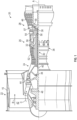
- FIG. 1 schematically illustrates a gas turbine engine 20.
- the gas turbine engine 20 is disclosed herein as a two-spool turbofan that generally incorporates a fan section 22, a compressor section 24, a combustor section 26 and a turbine section 28.
- Alternative engines might include other systems or features.
- the fan section 22 drives air along a bypass flow path B in a bypass duct, while the compressor section 24 drives air along a core flow path C for compression and communication into the combustor section 26 then expansion through the turbine section 28.
- FIG. 1 schematically illustrates a gas turbine engine 20.
- the gas turbine engine 20 is disclosed herein as a two-spool turbofan that generally incorporates a fan section 22, a compressor section 24, a combustor section 26 and a turbine section 28.
- Alternative engines might include other systems or features.
- the fan section 22 drives air along a bypass flow path B in a bypass duct
- the compressor section 24 drives air along a core flow path C for compression and communication into the combustor section 26
- the exemplary engine 20 generally includes a low speed spool 30 and a high speed spool 32 mounted for rotation about an engine central longitudinal axis A relative to an engine static structure 36 via several bearing systems 38. It should be understood that various bearing systems 38 at various locations may alternatively or additionally be provided, and the location of bearing systems 38 may be varied as appropriate to the application.
- the low speed spool 30 generally includes an inner shaft 40 that interconnects a fan 42, a first or low pressure compressor 44 and a first or low pressure turbine 46.
- the inner shaft 40 is connected to the fan 42 through a speed change mechanism, which in exemplary gas turbine engine 20 is illustrated as a geared architecture 48 to drive the fan 42 at a lower speed than the low speed spool 30.
- the high speed spool 32 includes an outer shaft 50 that interconnects a second or high pressure compressor 52 and a second or high pressure turbine 54.
- a combustor 56 is arranged in exemplary gas turbine 20 between the high pressure compressor 52 and the high pressure turbine 54.
- a mid-turbine frame 57 of the engine static structure 36 is arranged generally between the high pressure turbine 54 and the low pressure turbine 46.
- the mid-turbine frame 57 further supports bearing systems 38 in the turbine section 28.
- the inner shaft 40 and the outer shaft 50 are concentric and rotate via bearing systems 38 about the engine central longitudinal axis A which is collinear with their longitudinal axe
- the core airflow is compressed by the low pressure compressor 44 then the high pressure compressor 52, mixed and burned with fuel in the combustor 56, then expanded over the high pressure turbine 54 and low pressure turbine 46.
- the mid-turbine frame 57 includes airfoils 59 which are in the core airflow path C.
- the turbines 46, 54 rotationally drive the respective low speed spool 30 and high speed spool 32 in response to the expansion.
- gear system 48 may be located aft of combustor section 26 or even aft of turbine section 28, and fan section 22 may be positioned forward or aft of the location of gear system 48.
- the engine 20 in one example is a high-bypass geared aircraft engine. It is also understood, that the engine 20 illustrated in FIGS. 1 and 2 is merely exemplary and the present disclosure is contemplated for use with any type of gas turbine engine (geared or otherwise).
- FIG. 2 illustrates a portion of the high pressure turbine (HPT) 54.
- FIG. 2 also illustrates a high pressure turbine stage vanes 70 one of which (e.g., a first stage vane 71) is located forward of a first one of a pair of turbine disks 72 each having a plurality of turbine blades 74 secured thereto.
- the turbine blades 74 rotate proximate to blade outer air seals (BOAS) 75 which are located aft of the first stage vane 71.
- BOAS blade outer air seals
- the other vane 70 is located between the pair of turbine disks 72. This vane 70 may be referred to as the second stage vane 73.
- the first stage vane 71 is the first vane of the high pressure turbine section 54 that is located aft of the combustor section 26 and the second stage vane 73 is located aft of the first stage vane 71 and is located between the pair of turbine disks 72.
- blade outer air seals (BOAS) 75 are disposed between the first stage vane 71 and the second stage vane 73.
- the high pressure turbine stage vanes 70 e.g., first stage vane 71 or second stage vane 73
- the high pressure turbine is subjected to gas temperatures well above the yield capability of its material.
- surface film-cooling is typically used to cool the blades and vanes of the high pressure turbine.
- Surface film-cooling is achieved by supplying cooling air from the cold backside through cooling holes drilled on the high pressure turbine components. Cooling holes are strategically designed and placed on the vane and turbine components in-order to maximize the cooling effectiveness and minimize the efficiency penalty.
- internal cooling passageways and interconnecting cooling openings or crossovers are provided to allow for cooling air flow within the blades and vanes of the high pressure turbine.
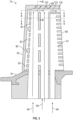
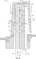
- FIGS. 3-6 a portion of an airfoil 80 of a turbine blade 74 is illustrated in accordance with the present disclosure.
- the airfoil 80 extends from a platform 81 of the turbine blade 74.
- An external wall of the airfoil 80 defines an external surface of the airfoil 80 having a leading edge 82, a pressure side 84, a suction side 86 and a trailing edge 88 of the airfoil 80 and extends to a tip 89 of the airfoil 80.
- the airfoil 80 also has a plurality of internal cooling cavities which include a leading edge cavity 90, main body cavities 92, pressure side skin core passages 94, suction side skin core passages 96, and a trailing edge feed cavity 97. These cavities and passages are provided with cooling air through cooling air supplied to bottom portions of the cavities and passages as illustrated in at least FIGS. 3 and 3A by arrows 99.
- the airfoil 80 may have only a single main body cavity 92 or at least two main body cavities 92 as illustrated.
- the airfoil 80 also has a squealer pocket 98 and a tip plenum 100 each being located proximate to the tip 89 of the airfoil 80.
- the squealer pocket 98 is located proximate to the suction side 86 and the tip plenum 100 is located proximate to the pressure side 84.
- the squealer pocket 98 and tip plenum 100 each extend axially along a portion of the airfoil 80.
- the tip plenum 100 as it extends toward the trailing edge 88 is located proximate to both the suction side 86 and the pressure side 84 of the airfoil 80. Cooling airflow from the suction side skin core passages 96 is provided to the squealer pocket 98 as the squealer pocket 98 is in fluid communication with the suction side skin core passages 96.
- the fluid communication between the suction side skin core passages 96 and the squealer pocket 98 is the only discharge of the fluid within the suction side skin core passages 96.
- the suction side skin core passages 96 also provide cooling air to the suction side 86 via cooling holes 102 that are in fluid communication with the suction side skin core passages 96. This is illustrated by arrows 104 illustrated in at least FIG. 6 .
- the pressure side skin core passages 94 also provide cooling air to the pressure side 84 via cooling holes 106 that are in fluid communication with the pressure side skin core passages 94. This is illustrated by arrows 108 illustrated in at least FIG. 6 .
- the airfoil tip 89 also includes a tip shelf 110.
- Some multiwall airfoil designs have relied on pressure side cooling passages 94 and suction side cooling passages 96 to cool the airfoil tip 89 via the tip plenum 100.
- this air has already been used to cool the pressure side cooling passages 94 and suction side cooling passages 96, this air has been heated by the external surfaces of the airfoil 80.
- This heating of the cooling air by the external surfaces of the airfoil can be on the order of several hundred degrees. As such, the cooling air may be significantly heated by the external surface prior to it reaching the tip 89 of the airfoil 80.
- tip plenums are typically the end of the road for the cooling air before out of exiting cooling holes, the mach numbers of the cooling air in the tip plenum can be pretty low, resulting in low heat transfer coefficients.
- the present disclosure incorporates a tip plenum 100 that is connected to the main body cavities 92 as opposed to the pressure side skin core passages 94 and suction side skin core passages 96.
- the main body cavity or cavities 92 are isolated thermally and fluidly from the pressure side cooling passages 94 and suction side cooling passages 96.
- the tip plenum 100 is only provided with cooling air from the main body cavity or cavities 92.
- the cooling air provided to the tip plenum 100 from the main body cavities 92 is insulated from external heated surfaces acting on the pressure side skin core passages 94 and the suction side skin core passages 96 thus resulting in very little heat up of the cooling air in the main body cavities 92 by the external surfaces of the airfoil 80 prior to it reaching the tip plenum 100.
- interior walls 112 of the airfoil 80 further insulate the main body cavities 92 from the pressure side skin core passages 94 and the suction side skin core passages 96. These interior walls 112 also fluidly isolate the main body cavities 92 from the pressure side skin core passages 94 and the suction side skin core passages 96.
- the tip plenum 100 has a rectangular cross-section. Of course, other cross-section configurations are contemplated to be within the scope of the present disclosure.
- the pressure side skin core passages 94 and the suction side skin core passages 96 are isolated from the tip plenum 100, the pressure side skin core passages 94 and the suction side skin core passages 96 can be configured to optimize heat transfer for cooling the pressure side 84 and the suction side 86 instead of balancing the pressure side 84 and the suction side 86 heat transfer with tip cooling air heat up.
- the tip plenum 100 is fed from at least one main body cavity 92 that is insulated from the pressure side skin core passages 94 and the suction side skin core passages 96.
- the tip plenum is fed by only a single main body cavity 92 or alternatively at least two main body cavities 92.
- main body cavities 92 are contemplated to be within the scope of the present disclosure.
- the tip plenum 100 is located below the airfoil tip 89 and the tip shelf 110. Portions of the tip plenum 100 are also located above a top portion 114 of the pressure side skin core passages 94. For example and as illustrated in at least FIG.
- a wall 116 is located between the top portion 114 of the pressure side skin core passages 94 and portions of the tip plenum 100. Also a wall 118 of the airfoil 80 is also located between portions of the tip plenum 100 and the tip shelf 110.
- the tip plenum 100 also extends towards the trailing edge 88 of the airfoil 80. In one embodiment, the tip plenum 100 extends all the way to the trailing edge 88 of the airfoil 80 such that airflow through the tip plenum 100 exits at an opening 120 illustrated by at least arrow 122.
- the tip plenum 100 which is fed cooling air from at least one main body cavity 92 drags this cooling air across nearly the entire tip 89 of the airfoil 80 extending proximate to the pressure side 84, resulting in high heat transfer.
- the tip plenum 100 is also in fluid communication with the tip shelf 110 via cooling openings 124 such that cooling air is provided to the tip shelf 110 from the tip plenum 100, which is insulated from the pressure side skin core passages 94 and the suction side skin core passages 96. This airflow is at least illustrated by arrows 126. As such, the cooling air fed to the tip shelf 110 via the cooling holes 124 also has very little heat build up.
- the squealer pocket 98 is in fluid communication with the suction side skin core passages 96 via a suction side tip plenum 128 that is in fluid communication with the suction side skin core passages 96 and passages 130 that provide fluid communication between the squealer pocket 98 and the suction side tip plenum 128.
- the squealer pocket 98 is fed separately from the suction side skin core passages 96.
- the tip plenum 100 is located proximate to the tip 89, the suction side plenum 128 which is adjacent to the tip plenum 100 is much smaller resulting in higher heat transfer.
- the squealer pocket 98 is located proximate to the suction side 86 of the airfoil 80.
- the cooling air fed to the suction side squealer pocket 98 also provides cooling to the tip 89 of the airfoil 80 further reducing areas of the tip 89 that are uncooled.
- This direct fluid communication between the suction side skin core passages 96 and the squealer pocket 98 can help position the suction side skin core passages 96 when forming the core that is used for forming the airfoil 80.
- the core is configured to have the shape of the internal cavities and the material of the airfoil 80 is positioned about the core as is known in the related arts and once the airfoil 80 is formed, the core is removed thereafter leaving the cavities and passages defined by the core.
- FIG. 7 an alternative embodiment of the present disclosure is illustrated.
- the view in FIG. 7 is similar to the view illustrated in FIG. 5 however, the leading edge cavity 90, main body cavities 92, pressure side skin core passages 94, suction side skin core passages 96, and trailing edge feed cavity 97 may be configured to have angled surfaces such that the pressure side skin core passages 94, suction side skin core passages 96 are generally triangular in shape and are interwoven or partially inserted in between complementary angled surfaces of the main body cavities 92 and trailing edge feed cavity 97.
- at least some portions of the main body cavities 92 may have a generally diamond shape.
- FIG. 8 is a similar view to FIG. 6 where the cooling airflow in the main body cavity 92 is illustrated by arrow 132. As illustrated, the airflow has to turn 90 degrees to enter the tip plenum 100. This turn may increase a pressure drop and likelihood of flow separation.
- the wall 116 located between the top portion 114 of the pressure side skin core passages 94 and portions of the tip plenum 100 may create a stiff box structure, which may result in higher stresses from between the colder inner wall 134 and the hotter outer wall 136.
- the wall 116 separating the top portion 114 of the pressure side skin core passages 94 and a bottom portion 140 of the tip plenum 100 is angled.
- the angle of the wall 116 may be anywhere between 30 and 70 degrees from a horizontal line 138 extending from the airfoil 80. Of course, other angles are contemplated to be within the scope of the present disclosure.
- the top 114 of the pressure side skin core passages 94 and the bottom portion 140 of the tip plenum 100 is angled to correspond to the angle of wall 116. This angled surface allows the cooling airflow in the main body cavity 92, as illustrated by arrow 142, to turn less than 90 degrees to enter the tip plenum 100.
- the angled wall 116 also provides a compliant flexible structure resulting in lower stresses between the colder inner wall 134 and the hotter outer wall 136.
- the cooling hole opening 106 located closest to the top portion 114 of the pressure side skin core passages 94 is able to be closer to the tip 89 and/or the tip shelf 110 of the airfoil 80 thus allowing these cooling holes 106 on the pressure side 84 to be close to the tip 89 and the tip shelf 110 of the airfoil 80 as opposed to the design of the wall 114 illustrated in FIGS. 6 and 8 .
- the main body cavities 92 of a multiwall airfoil design are protected from external heat loads by the pressure side and suction side skin core cooling cavities 94, 96, thereby significantly reducing the heat up of the cooling air by several hundred degrees. Therefore and by exclusively connecting the tip plenum 100 to the main body cavities 92, colder air or unheated air is provided to the tip plenum 100.
- the angled wall 116 in the alternative embodiment of FIG. 9 reduces the amount of turning that the cooling air has to do to enter the tip plenum 100 from the main body cavities 92, resulting in better flow quality, tip plenum cavity fill, and less pressure drop.
- the angled wall 116 provides a compliant, flexible structure between the colder inner wall 134 and the hotter outer wall 136, resulting in less stress from the thermal fight between the colder inner wall 134 and the hotter outer wall 136.
- the heat transfer along the pressure and suction sides 84, 86 of the airfoil 80 can be optimized for cooling the pressure and suction sides 84, 86, instead of having to balance the cooling of the pressure and suction sides 84, 86 with the tip cooling air heat up.
- a squealer pocket 98 that is connected to the suction side skin core cooling cavities 96 this provides an exit for the cooling air travelling through the suction side skin core cavities 96, maintaining high mach numbers in the suction side skin core cavities 96. In addition, it provides an additional source of cooling for the tip 89 and reduces the size of uncooled tip mass.
- the squealer pocket 98 prints outside the airfoil 80 and can be held onto by the core and wax dies used to form the airfoil 80, connecting the suction side skin core to the squealer pocket 98 provides a way to maintain the suction side cavity 96 position during the casting process, resulting in better wall control.
Landscapes
- Engineering & Computer Science (AREA)
- Mechanical Engineering (AREA)
- General Engineering & Computer Science (AREA)
- Turbine Rotor Nozzle Sealing (AREA)
Abstract
A blade for a gas turbine engine includes an airfoil (80) having a leading edge (82), a pressure side (84), a suction side (86) and a trailing edge (88) that extend to a tip (89) of the airfoil (80); a leading edge cavity (90) located within the airfoil (80); at least one main body cavity (92) located within the airfoil (80); pressure side skin core passages (94) located within the airfoil (80); suction side skin core passages (96) located within the airfoil (80), the at least one main body cavity (92) being fluidly isolated from the pressure side skin core passages (94) and the suction side skin core passages (96) and the at least one main body cavity (92) being located between the pressure side skin core passages (94) and the suction side skin core passages; a trailing edge feed cavity located within the airfoil (80); and a tip plenum (100) located proximate to the tip (89) of the airfoil (80), the tip plenum (100) being fluidly coupled to the at least one main body cavity (92), wherein the tip plenum (100) is located above the pressure side skin core passages (94) and the trailing edge feed cavity and extends to the trailing edge of the airfoil (80).
Description
- This disclosure relates to cooling schemes for components of a gas turbine engine, and more particularly to a component of a gas turbine engine with internal cooling cavities.
- Gas turbine engines typically include a compressor section, a combustor section and a turbine section. During operation, air is pressurized in the compressor section and is mixed with fuel and burned in the combustor section to generate hot combustion gases. The hot combustion gases are communicated through the turbine section, which extracts energy from the hot combustion gases to power the compressor section and other gas turbine engine loads.
- Both the compressor and turbine sections may include alternating series of rotating blades and stationary vanes that extend into the core flow path of the gas turbine engine. For example, in the turbine section, turbine blades rotate and extract energy from the hot combustion gases that are communicated along the core flow path of the gas turbine engine. The turbine vanes, which generally do not rotate, guide the airflow and prepare it for the next set of blades. In order to protect the rotating blades and stationary vanes from the deleterious effects of the hot combustion gases cooling air is provided to internal cavities of the blades and vanes however and since this cooling air is used to cool the pressure side and suction side of the airfoil or vane it is already significantly heated prior to it reaching a tip of the airfoil or vane.
- Accordingly, it is desirable to provide a blades or vanes with internal configurations wherein the cooling air is capable of reaching the tip of the airfoil prior to it being excessively heated.
- Disclosed is a blade for a gas turbine engine, including: an airfoil having a leading edge, a pressure side, a suction side and a trailing edge that extend to a tip of the airfoil; a leading edge cavity located within the airfoil; at least one main body cavity located within the airfoil; pressure side skin core passages located within the airfoil; suction side skin core passages located within the airfoil, the at least one main body cavity being fluidly isolated from the pressure side skin core passages and the suction side skin core passages and the at least one main body cavity being located between the pressure side skin core passages and the suction side skin core passages; a trailing edge feed cavity located within the airfoil; and a tip plenum located proximate to the tip of the airfoil, the tip plenum being fluidly coupled to the at least one main body cavity, wherein the tip plenum is located above the pressure side skin core passages and the trailing edge feed cavity and extends to the trailing edge of the airfoil.
- In an embodiment of the above, a tip shelf located in the tip of the airfoil, a portion of the tip plenum being located below the tip shelf, the tip shelf extending to the pressure side of the airfoil.
- In a further embodiment of any of the above, a squealer pocket is located in the tip of the airfoil, the squealer pocket being located proximate to the suction side of the airfoil.
- In a further embodiment of any of the above, the squealer pocket is fluidly coupled to a suction side tip plenum that extends proximate to the suction side of the airfoil, the suction side tip plenum is fluidly coupled to the suction side skin core passages.
- In a further embodiment of any of the above, cooling openings extend from the tip shelf to the tip plenum.
- In a further embodiment of any of the above, an opening is located at the trailing edge of the airfoil, the opening being fluidly coupled to the tip plenum.
- In a further embodiment of any of the above, the blade is a turbine blade.
- In a further embodiment of any of the above, the tip plenum has a rectangular cross-section.
- In a further embodiment of any of the above, the at least one main body cavity is a pair of main body cavities.
- In a further embodiment of any of the above, a wall is located between a top portion of the pressure side skin core passages and a bottom of the tip plenum, the wall being angularly arranged with respect to a horizontal line extending from the airfoil.
- In a further embodiment of any of the above, the wall is angularly arranged with an angle between 30 and 70 degrees with respect to the horizontal line.
- In a further embodiment of any of the above, the leading edge cavity, the at least one main body cavity, pressure side skin core passages, suction side skin core passages, and trailing edge feed cavity are configured to have angled surfaces such that the pressure side skin core passages, suction side skin core passages are generally triangular in shape and are interwoven or partially inserted in between complementary angled surfaces of the at least one main body cavity and trailing edge feed cavity.
- In a further embodiment of any of the above, the at least one main body cavity is a pair of main body cavities.
- Also disclosed is a gas turbine engine, including: a fan section; a compressor section; a combustor section; and a turbine section, the turbine section having a plurality blades, each of the plurality of blades having an airfoil, the airfoil having a leading edge, a pressure side, a suction side and a trailing edge that extend to a tip of the airfoil; a leading edge cavity located within the airfoil; at least one main body cavity located within the airfoil; pressure side skin core passages located within the airfoil; suction side skin core passages located within the airfoil, the at least one main body cavity being fluidly isolated from the pressure side skin core passages and the suction side skin core passages and the at least one main body cavity being located between the pressure side skin core passages and the suction side skin core passages; a trailing edge feed cavity located within the airfoil; and a tip plenum located proximate to the tip of the airfoil, the tip plenum being fluidly coupled to the at least one main body cavity, wherein the tip plenum is located above the pressure side skin core passages and the trailing edge feed cavity and extends to the trailing edge of the airfoil.
- In an embodiment of the above, a tip shelf is located in the tip of the airfoil, a portion of the tip plenum being located below the tip shelf, the tip shelf extending to the pressure side of the airfoil.
- In a further embodiment of any of the above, a squealer pocket is located in the tip of the airfoil, the squealer pocket being located proximate to the suction side of the airfoil.
- In a further embodiment of any of the above, the squealer pocket is fluidly coupled to a suction side tip plenum that extends proximate to the suction side of the airfoil, the suction side tip plenum is fluidly coupled to the suction side skin core passages.
- In a further embodiment of any of the above, a wall is located between a top portion of the pressure side skin core passages and a bottom of the tip plenum, the wall being angularly arranged with respect to a horizontal line extending from the airfoil.
- In a further embodiment of any of the above, the wall is angularly arranged with an angle between 30 and 70 degrees with respect to the horizontal line.
- Also disclosed is a method for cooling a tip of an airfoil of a blade of a gas turbine engine, including: providing cooling air to a tip plenum located proximate to the tip of the airfoil, the tip plenum being fluidly coupled to at least one main body cavity, the at least one main body cavity being isolated from pressure side skin core passages and suction side skin core passages and the at least one main body cavity being located between the pressure side skin core passages and the suction side skin core passages, wherein the tip plenum is located above the pressure side skin core passages and a trailing edge feed cavity and extends to a trailing edge of the airfoil.
- The following descriptions should not be considered limiting in any way. With reference to the accompanying drawings, like elements are numbered alike:
-
FIG. 1 is a schematic, partial cross-sectional view of a gas turbine engine; -
FIG. 2 is a view of a portion of a turbine section of the gas turbine engine illustrated inFIG. 1 ; -
FIG. 3 is a cross-sectional view of a turbine blade in accordance with the present disclosure; -
FIG. 3A is a cross-sectional view of a turbine blade in accordance with the present disclosure; -
FIG. 4 is a view along lines 4-4 ofFIGS. 3 and3A ; -
FIG. 5 is a view along lines 5-5 ofFIGS. 3 and3A ; -
FIG. 6 is a view along lines 6-6 ofFIGS. 3 and3A ; -
FIG. 7 is a view of an alternative embodiment of the present disclosure along lines 5-5 ofFIGS. 3 and3A ; -
FIG. 8 is another view along lines 6-6 ofFIGS. 3 and3A ; and -
FIG. 9 is a view of an alternative embodiment of the present disclosure along lines 6-6 ofFIGS. 3 and3A . - A detailed description of one or more embodiments of the disclosed apparatus and method are presented herein by way of exemplification and not limitation with reference to the FIGS.
-
FIG. 1 schematically illustrates agas turbine engine 20. Thegas turbine engine 20 is disclosed herein as a two-spool turbofan that generally incorporates afan section 22, acompressor section 24, acombustor section 26 and aturbine section 28. Alternative engines might include other systems or features. Thefan section 22 drives air along a bypass flow path B in a bypass duct, while thecompressor section 24 drives air along a core flow path C for compression and communication into thecombustor section 26 then expansion through theturbine section 28. Although depicted as a two-spool turbofan gas turbine engine in the disclosed non-limiting embodiment, it should be understood that the concepts described herein are not limited to use with two-spool turbofans as the teachings may be applied to other types of turbine engines including three-spool architectures. - The
exemplary engine 20 generally includes alow speed spool 30 and ahigh speed spool 32 mounted for rotation about an engine central longitudinal axis A relative to an enginestatic structure 36 viaseveral bearing systems 38. It should be understood thatvarious bearing systems 38 at various locations may alternatively or additionally be provided, and the location ofbearing systems 38 may be varied as appropriate to the application. - The
low speed spool 30 generally includes aninner shaft 40 that interconnects afan 42, a first orlow pressure compressor 44 and a first orlow pressure turbine 46. Theinner shaft 40 is connected to thefan 42 through a speed change mechanism, which in exemplarygas turbine engine 20 is illustrated as a gearedarchitecture 48 to drive thefan 42 at a lower speed than thelow speed spool 30. Thehigh speed spool 32 includes anouter shaft 50 that interconnects a second orhigh pressure compressor 52 and a second orhigh pressure turbine 54. Acombustor 56 is arranged inexemplary gas turbine 20 between thehigh pressure compressor 52 and thehigh pressure turbine 54. Amid-turbine frame 57 of the enginestatic structure 36 is arranged generally between thehigh pressure turbine 54 and thelow pressure turbine 46. Themid-turbine frame 57 further supports bearingsystems 38 in theturbine section 28. Theinner shaft 40 and theouter shaft 50 are concentric and rotate viabearing systems 38 about the engine central longitudinal axis A which is collinear with their longitudinal axes. - The core airflow is compressed by the
low pressure compressor 44 then thehigh pressure compressor 52, mixed and burned with fuel in thecombustor 56, then expanded over thehigh pressure turbine 54 andlow pressure turbine 46. Themid-turbine frame 57 includesairfoils 59 which are in the core airflow path C. Theturbines low speed spool 30 andhigh speed spool 32 in response to the expansion. It will be appreciated that each of the positions of thefan section 22,compressor section 24,combustor section 26,turbine section 28, and fandrive gear system 48 may be varied. For example,gear system 48 may be located aft ofcombustor section 26 or even aft ofturbine section 28, andfan section 22 may be positioned forward or aft of the location ofgear system 48. - The
engine 20 in one example is a high-bypass geared aircraft engine. It is also understood, that theengine 20 illustrated inFIGS. 1 and2 is merely exemplary and the present disclosure is contemplated for use with any type of gas turbine engine (geared or otherwise). -
FIG. 2 illustrates a portion of the high pressure turbine (HPT) 54.FIG. 2 also illustrates a high pressureturbine stage vanes 70 one of which (e.g., a first stage vane 71) is located forward of a first one of a pair ofturbine disks 72 each having a plurality ofturbine blades 74 secured thereto. Theturbine blades 74 rotate proximate to blade outer air seals (BOAS) 75 which are located aft of thefirst stage vane 71. Theother vane 70 is located between the pair ofturbine disks 72. Thisvane 70 may be referred to as thesecond stage vane 73. As used herein thefirst stage vane 71 is the first vane of the highpressure turbine section 54 that is located aft of thecombustor section 26 and thesecond stage vane 73 is located aft of thefirst stage vane 71 and is located between the pair ofturbine disks 72. In addition, blade outer air seals (BOAS) 75 are disposed between thefirst stage vane 71 and thesecond stage vane 73. The high pressure turbine stage vanes 70 (e.g.,first stage vane 71 or second stage vane 73) are one of a plurality ofvanes 70 that are positioned circumferentially about the axis A of the engine in order to provide astator assembly 76. Hot gases from thecombustor section 26 flow through the turbine in the direction ofarrow 77. Although a two-stage high pressure turbine is illustrated other high pressure turbines are considered to be within the scope of various embodiments of the present disclosure. - The high pressure turbine (HPT) is subjected to gas temperatures well above the yield capability of its material. In order to mitigate such high temperature detrimental effects, surface film-cooling is typically used to cool the blades and vanes of the high pressure turbine. Surface film-cooling is achieved by supplying cooling air from the cold backside through cooling holes drilled on the high pressure turbine components. Cooling holes are strategically designed and placed on the vane and turbine components in-order to maximize the cooling effectiveness and minimize the efficiency penalty.
- In addition, internal cooling passageways and interconnecting cooling openings or crossovers are provided to allow for cooling air flow within the blades and vanes of the high pressure turbine.
- Referring now to at least
FIGS. 3-6 , a portion of anairfoil 80 of aturbine blade 74 is illustrated in accordance with the present disclosure. Although, a turbine blade is illustrated it is understood that various embodiments of the present disclosure may be applied to other rotating blades employed in theengine 20. Theairfoil 80 extends from aplatform 81 of theturbine blade 74. An external wall of theairfoil 80 defines an external surface of theairfoil 80 having a leadingedge 82, apressure side 84, asuction side 86 and a trailingedge 88 of theairfoil 80 and extends to atip 89 of theairfoil 80. Theairfoil 80 also has a plurality of internal cooling cavities which include aleading edge cavity 90,main body cavities 92, pressure sideskin core passages 94, suction sideskin core passages 96, and a trailingedge feed cavity 97. These cavities and passages are provided with cooling air through cooling air supplied to bottom portions of the cavities and passages as illustrated in at leastFIGS. 3 and3A byarrows 99. Theairfoil 80 may have only a singlemain body cavity 92 or at least twomain body cavities 92 as illustrated. - The
airfoil 80 also has asquealer pocket 98 and atip plenum 100 each being located proximate to thetip 89 of theairfoil 80. Thesquealer pocket 98 is located proximate to thesuction side 86 and thetip plenum 100 is located proximate to thepressure side 84. Thesquealer pocket 98 andtip plenum 100 each extend axially along a portion of theairfoil 80. Thetip plenum 100 as it extends toward the trailingedge 88 is located proximate to both thesuction side 86 and thepressure side 84 of theairfoil 80. Cooling airflow from the suction sideskin core passages 96 is provided to thesquealer pocket 98 as thesquealer pocket 98 is in fluid communication with the suction sideskin core passages 96. - In some embodiments, the fluid communication between the suction side
skin core passages 96 and thesquealer pocket 98 is the only discharge of the fluid within the suction sideskin core passages 96. In other embodiments, the suction sideskin core passages 96 also provide cooling air to thesuction side 86 via cooling holes 102 that are in fluid communication with the suction sideskin core passages 96. This is illustrated byarrows 104 illustrated in at leastFIG. 6 . The pressure sideskin core passages 94 also provide cooling air to thepressure side 84 via cooling holes 106 that are in fluid communication with the pressure sideskin core passages 94. This is illustrated byarrows 108 illustrated in at leastFIG. 6 . Theairfoil tip 89 also includes atip shelf 110. - Some multiwall airfoil designs have relied on pressure
side cooling passages 94 and suctionside cooling passages 96 to cool theairfoil tip 89 via thetip plenum 100. However, because this air has already been used to cool the pressureside cooling passages 94 and suctionside cooling passages 96, this air has been heated by the external surfaces of theairfoil 80. This heating of the cooling air by the external surfaces of the airfoil can be on the order of several hundred degrees. As such, the cooling air may be significantly heated by the external surface prior to it reaching thetip 89 of theairfoil 80. In addition and since tip plenums are typically the end of the road for the cooling air before out of exiting cooling holes, the mach numbers of the cooling air in the tip plenum can be pretty low, resulting in low heat transfer coefficients. - The present disclosure incorporates a
tip plenum 100 that is connected to themain body cavities 92 as opposed to the pressure sideskin core passages 94 and suction sideskin core passages 96. In addition, the main body cavity orcavities 92 are isolated thermally and fluidly from the pressureside cooling passages 94 and suctionside cooling passages 96. In other words, thetip plenum 100 is only provided with cooling air from the main body cavity orcavities 92. As such, the cooling air provided to thetip plenum 100 from themain body cavities 92 is insulated from external heated surfaces acting on the pressure sideskin core passages 94 and the suction sideskin core passages 96 thus resulting in very little heat up of the cooling air in themain body cavities 92 by the external surfaces of theairfoil 80 prior to it reaching thetip plenum 100. In addition,interior walls 112 of theairfoil 80 further insulate themain body cavities 92 from the pressure sideskin core passages 94 and the suction sideskin core passages 96. Theseinterior walls 112 also fluidly isolate themain body cavities 92 from the pressure sideskin core passages 94 and the suction sideskin core passages 96. In one non-limiting embodiment, thetip plenum 100 has a rectangular cross-section. Of course, other cross-section configurations are contemplated to be within the scope of the present disclosure. - In addition and since the pressure side
skin core passages 94 and the suction sideskin core passages 96 are isolated from thetip plenum 100, the pressure sideskin core passages 94 and the suction sideskin core passages 96 can be configured to optimize heat transfer for cooling thepressure side 84 and thesuction side 86 instead of balancing thepressure side 84 and thesuction side 86 heat transfer with tip cooling air heat up. - As such, the
tip plenum 100 is fed from at least onemain body cavity 92 that is insulated from the pressure sideskin core passages 94 and the suction sideskin core passages 96. In one non-limiting embodiment, the tip plenum is fed by only a singlemain body cavity 92 or alternatively at least two main body cavities 92. Of course, other numbers ofmain body cavities 92 are contemplated to be within the scope of the present disclosure. As illustrated in at leastFIGS. 4 and6 , thetip plenum 100 is located below theairfoil tip 89 and thetip shelf 110. Portions of thetip plenum 100 are also located above atop portion 114 of the pressure sideskin core passages 94. For example and as illustrated in at leastFIG. 6 , awall 116 is located between thetop portion 114 of the pressure sideskin core passages 94 and portions of thetip plenum 100. Also awall 118 of theairfoil 80 is also located between portions of thetip plenum 100 and thetip shelf 110. Thetip plenum 100 also extends towards the trailingedge 88 of theairfoil 80. In one embodiment, thetip plenum 100 extends all the way to the trailingedge 88 of theairfoil 80 such that airflow through thetip plenum 100 exits at anopening 120 illustrated by at leastarrow 122. - The
tip plenum 100 which is fed cooling air from at least onemain body cavity 92 drags this cooling air across nearly theentire tip 89 of theairfoil 80 extending proximate to thepressure side 84, resulting in high heat transfer. In addition and since there is extra airflow out of thetip plenum 100 through theopening 120 at the trailingedge 88, this pulls extra airflow across thetip 89 at higher mach numbers and heat transfer coefficients thus improving cooling of thetip 89 of theairfoil 80. - The
tip plenum 100 is also in fluid communication with thetip shelf 110 via coolingopenings 124 such that cooling air is provided to thetip shelf 110 from thetip plenum 100, which is insulated from the pressure sideskin core passages 94 and the suction sideskin core passages 96. This airflow is at least illustrated byarrows 126. As such, the cooling air fed to thetip shelf 110 via the cooling holes 124 also has very little heat build up. - In addition and in the present disclosure, the
squealer pocket 98 is in fluid communication with the suction sideskin core passages 96 via a suctionside tip plenum 128 that is in fluid communication with the suction sideskin core passages 96 andpassages 130 that provide fluid communication between thesquealer pocket 98 and the suctionside tip plenum 128. Thus, thesquealer pocket 98 is fed separately from the suction sideskin core passages 96. In addition and since thetip plenum 100 is located proximate to thetip 89, thesuction side plenum 128 which is adjacent to thetip plenum 100 is much smaller resulting in higher heat transfer. As illustrated, thesquealer pocket 98 is located proximate to thesuction side 86 of theairfoil 80. The cooling air fed to the suctionside squealer pocket 98 also provides cooling to thetip 89 of theairfoil 80 further reducing areas of thetip 89 that are uncooled. This direct fluid communication between the suction sideskin core passages 96 and thesquealer pocket 98 can help position the suction sideskin core passages 96 when forming the core that is used for forming theairfoil 80. As is known in the related arts, the core is configured to have the shape of the internal cavities and the material of theairfoil 80 is positioned about the core as is known in the related arts and once theairfoil 80 is formed, the core is removed thereafter leaving the cavities and passages defined by the core. - Referring now to
FIG. 7 an alternative embodiment of the present disclosure is illustrated. The view inFIG. 7 is similar to the view illustrated inFIG. 5 however, theleading edge cavity 90,main body cavities 92, pressure sideskin core passages 94, suction sideskin core passages 96, and trailingedge feed cavity 97 may be configured to have angled surfaces such that the pressure sideskin core passages 94, suction sideskin core passages 96 are generally triangular in shape and are interwoven or partially inserted in between complementary angled surfaces of themain body cavities 92 and trailingedge feed cavity 97. For example and in one non-limiting embodiment, at least some portions of themain body cavities 92 may have a generally diamond shape. - Referring now to
FIGS. 8 and 9 , yet another alternative embodiment of the present disclosure is illustrated.FIG. 8 is a similar view toFIG. 6 where the cooling airflow in themain body cavity 92 is illustrated byarrow 132. As illustrated, the airflow has to turn 90 degrees to enter thetip plenum 100. This turn may increase a pressure drop and likelihood of flow separation. In addition, thewall 116 located between thetop portion 114 of the pressure sideskin core passages 94 and portions of thetip plenum 100 may create a stiff box structure, which may result in higher stresses from between the colderinner wall 134 and the hotterouter wall 136. - Referring now to
FIG. 9 , thewall 116 separating thetop portion 114 of the pressure sideskin core passages 94 and abottom portion 140 of thetip plenum 100 is angled. The angle of thewall 116 may be anywhere between 30 and 70 degrees from a horizontal line 138 extending from theairfoil 80. Of course, other angles are contemplated to be within the scope of the present disclosure. In addition, the top 114 of the pressure sideskin core passages 94 and thebottom portion 140 of thetip plenum 100 is angled to correspond to the angle ofwall 116. This angled surface allows the cooling airflow in themain body cavity 92, as illustrated byarrow 142, to turn less than 90 degrees to enter thetip plenum 100. This lesser turn may result in better flow quality, less pressure drop, and better fill of thetip plenum 100. Theangled wall 116 also provides a compliant flexible structure resulting in lower stresses between the colderinner wall 134 and the hotterouter wall 136. In addition and by providing thetop portion 114 of the pressure sideskin core passages 94 with an angled surface, thecooling hole opening 106 located closest to thetop portion 114 of the pressure sideskin core passages 94 is able to be closer to thetip 89 and/or thetip shelf 110 of theairfoil 80 thus allowing these cooling holes 106 on thepressure side 84 to be close to thetip 89 and thetip shelf 110 of theairfoil 80 as opposed to the design of thewall 114 illustrated inFIGS. 6 and8 . - In accordance with various embodiments of the present disclosure, the
main body cavities 92 of a multiwall airfoil design are protected from external heat loads by the pressure side and suction side skincore cooling cavities tip plenum 100 to themain body cavities 92, colder air or unheated air is provided to thetip plenum 100. - The
angled wall 116 in the alternative embodiment ofFIG. 9 reduces the amount of turning that the cooling air has to do to enter thetip plenum 100 from themain body cavities 92, resulting in better flow quality, tip plenum cavity fill, and less pressure drop. In addition, theangled wall 116 provides a compliant, flexible structure between the colderinner wall 134 and the hotterouter wall 136, resulting in less stress from the thermal fight between the colderinner wall 134 and the hotterouter wall 136. - In addition and by cooling the
tip 89 of theairfoil 80 with air from themain body cavities 92 instead of the pressure sideskin core passages 94 and the suction sideskin core passages 96, the heat transfer along the pressure andsuction sides airfoil 80 can be optimized for cooling the pressure andsuction sides suction sides - Still further and by incorporating a
squealer pocket 98 that is connected to the suction side skincore cooling cavities 96 this provides an exit for the cooling air travelling through the suction sideskin core cavities 96, maintaining high mach numbers in the suction sideskin core cavities 96. In addition, it provides an additional source of cooling for thetip 89 and reduces the size of uncooled tip mass. - Still further and since the
squealer pocket 98 prints outside theairfoil 80 and can be held onto by the core and wax dies used to form theairfoil 80, connecting the suction side skin core to thesquealer pocket 98 provides a way to maintain thesuction side cavity 96 position during the casting process, resulting in better wall control. - The term "about" is intended to include the degree of error associated with measurement of the particular quantity based upon the equipment available at the time of filing the application. For example, "about" can include a range of ± 8% or 5%, or 2% of a given value.
- The terminology used herein is for the purpose of describing particular embodiments only and is not intended to be limiting of the present disclosure. As used herein, the singular forms "a", "an" and "the" are intended to include the plural forms as well, unless the context clearly indicates otherwise. It will be further understood that the terms "comprises" and/or "comprising," when used in this specification, specify the presence of stated features, integers, steps, operations, elements, and/or components, but do not preclude the presence or addition of one or more other features, integers, steps, operations, element components, and/or groups thereof.
- While the present disclosure has been described with reference to an exemplary embodiment or embodiments, it will be understood by those skilled in the art that various changes may be made and equivalents may be substituted for elements thereof without departing from the scope of the present disclosure. In addition, many modifications may be made to adapt a particular situation or material to the teachings of the present disclosure without departing from the essential scope thereof. Therefore, it is intended that the present disclosure not be limited to the particular embodiment disclosed as the best mode contemplated for carrying out this present disclosure, but that the present disclosure will include all embodiments falling within the scope of the claims.
Claims (14)
- A blade for a gas turbine engine, comprising:an airfoil (80) having a leading edge (82), a pressure side (84), a suction side (86) and a trailing edge (88) that extend to a tip (89) of the airfoil (80);a leading edge cavity (90) located within the airfoil (80);at least one main body cavity (92) located within the airfoil (80);pressure side skin core passages (94) located within the airfoil (80);suction side skin core passages (96) located within the airfoil (80), the at least one main body cavity (92) being fluidly isolated from the pressure side skin core passages (94) and the suction side skin core passages (96), and the at least one main body cavity (92) being located between the pressure side skin core passages (94) and the suction side skin core passages (96);a trailing edge feed cavity (97) located within the airfoil (80); anda tip plenum (100) located proximate to the tip (89) of the airfoil (80), the tip plenum (100) being fluidly coupled to the at least one main body cavity (92), wherein the tip plenum (100) is located above the pressure side skin core passages (94) and the trailing edge feed cavity (97) and extends to the trailing edge (88) of the airfoil (80).
- The blade as claimed in claim 1, further comprising an opening (120) located at the trailing edge (88) of the airfoil (80), the opening (120) being fluidly coupled to the tip plenum (100).
- The blade as claimed in claim 1 or 2, wherein the blade (74) is a turbine blade (74).
- The blade as claimed in any preceding claim, wherein the tip plenum (100) has a rectangular cross-section.
- The blade as claimed in any preceding claim, wherein the at least one main body cavity (92) is a pair of main body cavities (92).
- The blade as claimed in any preceding claim, wherein the leading edge cavity (90), the at least one main body cavity (92), the pressure side skin core passages (94), the suction side skin core passages (96), and the trailing edge feed cavity (97) are configured to have angled surfaces such that the pressure side skin core passages (94) and the suction side skin core passages (96) are generally triangular in shape and are interwoven or partially inserted in between complementary angled surfaces of the at least one main body cavity (92) and trailing edge feed cavity (97).
- A gas turbine engine, comprising:a fan section (22);a compressor section (24);a combustor section (26); anda turbine section (54), the turbine section (54) having a plurality blades (74), each of the plurality of blades (74) being a blade as defined in any preceding claim.
- The blade or gas turbine engine as claimed in any preceding claim, further comprising a tip shelf (110) located in the tip (89) of the airfoil (80), a portion of the tip plenum (100) being located below the tip shelf (110), the tip shelf (110) extending to the pressure side (84) of the airfoil (80).
- The blade or gas turbine engine as claimed in claim 8, further comprising cooling openings (124) extending from the tip shelf (110) to the tip plenum (100).
- The blade or gas turbine engine as claimed in any preceding claim, further comprising a squealer pocket (98) located in the tip (89) of the airfoil (80), the squealer pocket (98) being located proximate to the suction side (86) of the airfoil (80).
- The blade or gas turbine engine as claimed in claim 10, wherein the squealer pocket (98) is fluidly coupled to a suction side tip plenum (100) that extends proximate to the suction side (86) of the airfoil (80), the suction side tip plenum (100) is fluidly coupled to the suction side skin core passages (96).
- The blade or gas turbine engine as claimed in any preceding claim, wherein a wall (116) is located between a top portion (114) of the pressure side skin core passages (94) and a bottom (140) of the tip plenum (100), the wall (116) being angularly arranged with respect to a horizontal line (138) extending from the airfoil (80).
- The blade or gas turbine engine as claimed in claim 12, wherein the wall (116) is angularly arranged with an angle between 30 and 70 degrees with respect to the horizontal line (138).
- A method for cooling a tip of an airfoil of a blade of a gas turbine engine, comprising:
providing cooling air to a tip plenum (100) located proximate to the tip (89) of the airfoil (80), the tip plenum (100) being fluidly coupled to at least one main body cavity (92), the at least one main body cavity (92) being isolated from pressure side skin core passages (94) and suction side skin core passages (96) and the at least one main body cavity (92) being located between the pressure side skin core passages (94) and the suction side skin core passages (96), wherein the tip plenum (100) is located above the pressure side skin core passages (94) and a trailing edge feed cavity (97) and extends to a trailing edge (88) of the airfoil (80).
Applications Claiming Priority (1)
| Application Number | Priority Date | Filing Date | Title |
|---|---|---|---|
| US18/118,365 US20240301799A1 (en) | 2023-03-07 | 2023-03-07 | Airfoil tip arrangement for gas turbine engine |
Publications (1)
| Publication Number | Publication Date |
|---|---|
| EP4428339A1 true EP4428339A1 (en) | 2024-09-11 |
Family
ID=90363331
Family Applications (1)
| Application Number | Title | Priority Date | Filing Date |
|---|---|---|---|
| EP24162007.9A Pending EP4428339A1 (en) | 2023-03-07 | 2024-03-07 | Blade for a gas turbine engine, gas turbine engine and method for cooling a tip of an airfoil of a blade of a gas turbine engine |
Country Status (2)
| Country | Link |
|---|---|
| US (1) | US20240301799A1 (en) |
| EP (1) | EP4428339A1 (en) |
Citations (5)
| Publication number | Priority date | Publication date | Assignee | Title |
|---|---|---|---|---|
| US6126396A (en) * | 1998-12-09 | 2000-10-03 | General Electric Company | AFT flowing serpentine airfoil cooling circuit with side wall impingement cooling chambers |
| US6164914A (en) * | 1999-08-23 | 2000-12-26 | General Electric Company | Cool tip blade |
| US7632062B2 (en) * | 2004-04-17 | 2009-12-15 | Rolls-Royce Plc | Turbine rotor blades |
| US20190120064A1 (en) * | 2017-10-24 | 2019-04-25 | United Technologies Corporation | Airfoil cooling circuit |
| US11459897B2 (en) * | 2019-05-03 | 2022-10-04 | Raytheon Technologies Corporation | Cooling schemes for airfoils for gas turbine engines |
Family Cites Families (17)
| Publication number | Priority date | Publication date | Assignee | Title |
|---|---|---|---|---|
| FR1452803A (en) * | 1965-08-02 | 1966-04-15 | Snecma | Improvement in cooling means of turbine blades or other parts |
| US5667359A (en) * | 1988-08-24 | 1997-09-16 | United Technologies Corp. | Clearance control for the turbine of a gas turbine engine |
| US6790005B2 (en) * | 2002-12-30 | 2004-09-14 | General Electric Company | Compound tip notched blade |
| US7195448B2 (en) * | 2004-05-27 | 2007-03-27 | United Technologies Corporation | Cooled rotor blade |
| US7097419B2 (en) * | 2004-07-26 | 2006-08-29 | General Electric Company | Common tip chamber blade |
| US7625178B2 (en) * | 2006-08-30 | 2009-12-01 | Honeywell International Inc. | High effectiveness cooled turbine blade |
| US7871246B2 (en) * | 2007-02-15 | 2011-01-18 | Siemens Energy, Inc. | Airfoil for a gas turbine |
| US9085980B2 (en) * | 2011-03-04 | 2015-07-21 | Honeywell International Inc. | Methods for repairing turbine components |
| US8985940B2 (en) * | 2012-03-30 | 2015-03-24 | Solar Turbines Incorporated | Turbine cooling apparatus |
| US9995148B2 (en) * | 2012-10-04 | 2018-06-12 | General Electric Company | Method and apparatus for cooling gas turbine and rotor blades |
| US10472970B2 (en) * | 2013-01-23 | 2019-11-12 | United Technologies Corporation | Gas turbine engine component having contoured rib end |
| CN106471215B (en) * | 2014-07-07 | 2018-06-19 | 西门子公司 | Gas-turbine blade squealer tip, corresponding manufacture and cooling means and gas-turbine unit |
| CN107109949A (en) * | 2014-11-11 | 2017-08-29 | 西门子公司 | Turbo blade with axial leaf top cooling circuit |
| WO2017039572A1 (en) * | 2015-08-28 | 2017-03-09 | Siemens Aktiengesellschaft | Turbine airfoil having flow displacement feature with partially sealed radial passages |
| US10301946B2 (en) * | 2016-10-26 | 2019-05-28 | General Electric Company | Partially wrapped trailing edge cooling circuits with pressure side impingements |
| US10907479B2 (en) * | 2018-05-07 | 2021-02-02 | Raytheon Technologies Corporation | Airfoil having improved leading edge cooling scheme and damage resistance |
| US11053803B2 (en) * | 2019-06-26 | 2021-07-06 | Raytheon Technologies Corporation | Airfoils and core assemblies for gas turbine engines and methods of manufacture |
-
2023
- 2023-03-07 US US18/118,365 patent/US20240301799A1/en active Pending
-
2024
- 2024-03-07 EP EP24162007.9A patent/EP4428339A1/en active Pending
Patent Citations (5)
| Publication number | Priority date | Publication date | Assignee | Title |
|---|---|---|---|---|
| US6126396A (en) * | 1998-12-09 | 2000-10-03 | General Electric Company | AFT flowing serpentine airfoil cooling circuit with side wall impingement cooling chambers |
| US6164914A (en) * | 1999-08-23 | 2000-12-26 | General Electric Company | Cool tip blade |
| US7632062B2 (en) * | 2004-04-17 | 2009-12-15 | Rolls-Royce Plc | Turbine rotor blades |
| US20190120064A1 (en) * | 2017-10-24 | 2019-04-25 | United Technologies Corporation | Airfoil cooling circuit |
| US11459897B2 (en) * | 2019-05-03 | 2022-10-04 | Raytheon Technologies Corporation | Cooling schemes for airfoils for gas turbine engines |
Also Published As
| Publication number | Publication date |
|---|---|
| US20240301799A1 (en) | 2024-09-12 |
Similar Documents
| Publication | Publication Date | Title |
|---|---|---|
| EP3354846B1 (en) | Aft flowing serpentine cavities and cores for airfoils of gas turbine engines | |
| EP3047105B1 (en) | Platform cooling core for a gas turbine engine rotor blade | |
| EP3330487B1 (en) | Leading edge hybrid cavities and cores for airfoils of gas turbine engine | |
| EP3342978B1 (en) | Integrated squealer pocket tip and tip shelf with hybrid and tip flag core | |
| US10519781B2 (en) | Airfoil turn caps in gas turbine engines | |
| EP3495617B1 (en) | Airfoil with internal cooling passages | |
| US11982231B2 (en) | Hourglass airfoil cooling configuration | |
| EP3346094B1 (en) | Radially diffused tip flag | |
| EP3399145B1 (en) | Airfoil comprising a leading edge hybrid skin core cavity | |
| US20190085705A1 (en) | Component for a turbine engine with a film-hole | |
| EP3508697B1 (en) | Gas turbine engine airfoil-platform cooling configuration with main core resupply | |
| EP3508696B1 (en) | Gas turbine engine airfoil-platform cooling configuration | |
| EP3498979B1 (en) | Cooled airfoil | |
| US20180023415A1 (en) | Air cooled component for a gas turbine engine | |
| EP3047111B1 (en) | Component for a gas turbine engine, corresponding gas turbine engine and method of cooling | |
| EP3495620B1 (en) | Airfoil with internal cooling passages | |
| EP3617454A1 (en) | Variable heat transfer collector baffle | |
| EP4428339A1 (en) | Blade for a gas turbine engine, gas turbine engine and method for cooling a tip of an airfoil of a blade of a gas turbine engine | |
| CN108779679A (en) | Cooled turbo blade | |
| EP3564485A1 (en) | Airfoils, cores, and methods of manufacture for forming airfoils having fluidly connected platform cooling circuits | |
| EP3011140B1 (en) | Gas turbine engine component with rib support | |
| EP4613980A1 (en) | Turbine vane with leading edge cooling | |
| EP3564486A1 (en) | Airfoil having improved cooling scheme | |
| EP4417790A1 (en) | Air foil with staggered cooling hole configuration | |
| EP3495619B1 (en) | Airfoil with internal cooling passages |
Legal Events
| Date | Code | Title | Description |
|---|---|---|---|
| PUAI | Public reference made under article 153(3) epc to a published international application that has entered the european phase |
Free format text: ORIGINAL CODE: 0009012 |
|
| STAA | Information on the status of an ep patent application or granted ep patent |
Free format text: STATUS: THE APPLICATION HAS BEEN PUBLISHED |
|
| AK | Designated contracting states |
Kind code of ref document: A1 Designated state(s): AL AT BE BG CH CY CZ DE DK EE ES FI FR GB GR HR HU IE IS IT LI LT LU LV MC ME MK MT NL NO PL PT RO RS SE SI SK SM TR |
|
| STAA | Information on the status of an ep patent application or granted ep patent |
Free format text: STATUS: REQUEST FOR EXAMINATION WAS MADE |
|
| 17P | Request for examination filed |
Effective date: 20250311 |