EP4428265A2 - Carbon dioxide conversion apparatus - Google Patents
Carbon dioxide conversion apparatus Download PDFInfo
- Publication number
- EP4428265A2 EP4428265A2 EP24153380.1A EP24153380A EP4428265A2 EP 4428265 A2 EP4428265 A2 EP 4428265A2 EP 24153380 A EP24153380 A EP 24153380A EP 4428265 A2 EP4428265 A2 EP 4428265A2
- Authority
- EP
- European Patent Office
- Prior art keywords
- gas
- carbon dioxide
- chamber
- oxygen
- partial oxidation
- Prior art date
- Legal status (The legal status is an assumption and is not a legal conclusion. Google has not performed a legal analysis and makes no representation as to the accuracy of the status listed.)
- Pending
Links
- CURLTUGMZLYLDI-UHFFFAOYSA-N Carbon dioxide Chemical compound O=C=O CURLTUGMZLYLDI-UHFFFAOYSA-N 0.000 title claims abstract description 228
- 229910002092 carbon dioxide Inorganic materials 0.000 title claims abstract description 190
- 239000001569 carbon dioxide Substances 0.000 title claims abstract description 161
- 238000006243 chemical reaction Methods 0.000 title claims abstract description 31
- 239000007789 gas Substances 0.000 claims abstract description 195
- 229910002091 carbon monoxide Inorganic materials 0.000 claims abstract description 118
- UGFAIRIUMAVXCW-UHFFFAOYSA-N Carbon monoxide Chemical compound [O+]#[C-] UGFAIRIUMAVXCW-UHFFFAOYSA-N 0.000 claims abstract description 117
- 239000001301 oxygen Substances 0.000 claims abstract description 90
- 229910052760 oxygen Inorganic materials 0.000 claims abstract description 90
- QVGXLLKOCUKJST-UHFFFAOYSA-N atomic oxygen Chemical compound [O] QVGXLLKOCUKJST-UHFFFAOYSA-N 0.000 claims abstract description 80
- 238000007254 oxidation reaction Methods 0.000 claims abstract description 58
- 239000000126 substance Substances 0.000 claims abstract description 58
- 230000003647 oxidation Effects 0.000 claims abstract description 57
- 238000003786 synthesis reaction Methods 0.000 claims abstract description 56
- 230000015572 biosynthetic process Effects 0.000 claims abstract description 53
- 238000005868 electrolysis reaction Methods 0.000 claims abstract description 41
- 239000001257 hydrogen Substances 0.000 claims abstract description 19
- 229910052739 hydrogen Inorganic materials 0.000 claims abstract description 19
- UFHFLCQGNIYNRP-UHFFFAOYSA-N Hydrogen Chemical compound [H][H] UFHFLCQGNIYNRP-UHFFFAOYSA-N 0.000 claims abstract description 16
- 239000012528 membrane Substances 0.000 claims description 27
- XLYOFNOQVPJJNP-UHFFFAOYSA-N water Substances O XLYOFNOQVPJJNP-UHFFFAOYSA-N 0.000 claims description 18
- -1 oxygen ion Chemical class 0.000 claims description 14
- 239000000446 fuel Substances 0.000 claims description 6
- 150000002431 hydrogen Chemical class 0.000 claims description 5
- 239000012476 oxidizable substance Substances 0.000 claims description 4
- VUZPPFZMUPKLLV-UHFFFAOYSA-N methane;hydrate Chemical compound C.O VUZPPFZMUPKLLV-UHFFFAOYSA-N 0.000 claims description 2
- 238000005259 measurement Methods 0.000 abstract description 22
- VNWKTOKETHGBQD-UHFFFAOYSA-N methane Chemical compound C VNWKTOKETHGBQD-UHFFFAOYSA-N 0.000 description 28
- 230000001105 regulatory effect Effects 0.000 description 28
- 238000000034 method Methods 0.000 description 19
- 238000006722 reduction reaction Methods 0.000 description 15
- 239000007788 liquid Substances 0.000 description 12
- 239000007864 aqueous solution Substances 0.000 description 10
- 239000008151 electrolyte solution Substances 0.000 description 10
- 238000010521 absorption reaction Methods 0.000 description 8
- 239000007787 solid Substances 0.000 description 8
- 150000001412 amines Chemical class 0.000 description 7
- BVKZGUZCCUSVTD-UHFFFAOYSA-L Carbonate Chemical compound [O-]C([O-])=O BVKZGUZCCUSVTD-UHFFFAOYSA-L 0.000 description 6
- 230000033228 biological regulation Effects 0.000 description 6
- 239000003792 electrolyte Substances 0.000 description 6
- 230000001172 regenerating effect Effects 0.000 description 6
- 238000000926 separation method Methods 0.000 description 6
- 230000001276 controlling effect Effects 0.000 description 5
- XLYOFNOQVPJJNP-UHFFFAOYSA-M hydroxide Chemical compound [OH-] XLYOFNOQVPJJNP-UHFFFAOYSA-M 0.000 description 5
- 239000000243 solution Substances 0.000 description 5
- BVKZGUZCCUSVTD-UHFFFAOYSA-M Bicarbonate Chemical compound OC([O-])=O BVKZGUZCCUSVTD-UHFFFAOYSA-M 0.000 description 4
- 239000004215 Carbon black (E152) Substances 0.000 description 4
- YZCKVEUIGOORGS-UHFFFAOYSA-N Hydrogen atom Chemical compound [H] YZCKVEUIGOORGS-UHFFFAOYSA-N 0.000 description 4
- 230000003247 decreasing effect Effects 0.000 description 4
- 229930195733 hydrocarbon Natural products 0.000 description 4
- 150000002430 hydrocarbons Chemical class 0.000 description 4
- OKKJLVBELUTLKV-UHFFFAOYSA-N Methanol Chemical compound OC OKKJLVBELUTLKV-UHFFFAOYSA-N 0.000 description 3
- KWYUFKZDYYNOTN-UHFFFAOYSA-M Potassium hydroxide Chemical compound [OH-].[K+] KWYUFKZDYYNOTN-UHFFFAOYSA-M 0.000 description 3
- 150000002500 ions Chemical group 0.000 description 3
- 238000001179 sorption measurement Methods 0.000 description 3
- 230000002194 synthesizing effect Effects 0.000 description 3
- BHPQYMZQTOCNFJ-UHFFFAOYSA-N Calcium cation Chemical compound [Ca+2] BHPQYMZQTOCNFJ-UHFFFAOYSA-N 0.000 description 2
- 229910052688 Gadolinium Inorganic materials 0.000 description 2
- JLVVSXFLKOJNIY-UHFFFAOYSA-N Magnesium ion Chemical compound [Mg+2] JLVVSXFLKOJNIY-UHFFFAOYSA-N 0.000 description 2
- FKNQFGJONOIPTF-UHFFFAOYSA-N Sodium cation Chemical compound [Na+] FKNQFGJONOIPTF-UHFFFAOYSA-N 0.000 description 2
- 229910001424 calcium ion Inorganic materials 0.000 description 2
- 229910002086 ceria-stabilized zirconia Inorganic materials 0.000 description 2
- 238000002485 combustion reaction Methods 0.000 description 2
- 239000002131 composite material Substances 0.000 description 2
- 238000012937 correction Methods 0.000 description 2
- 238000010586 diagram Methods 0.000 description 2
- 239000002803 fossil fuel Substances 0.000 description 2
- XLYOFNOQVPJJNP-ZSJDYOACSA-N heavy water Substances [2H]O[2H] XLYOFNOQVPJJNP-ZSJDYOACSA-N 0.000 description 2
- 229910001416 lithium ion Inorganic materials 0.000 description 2
- 229910001425 magnesium ion Inorganic materials 0.000 description 2
- 239000011533 mixed conductor Substances 0.000 description 2
- 238000002156 mixing Methods 0.000 description 2
- 230000001590 oxidative effect Effects 0.000 description 2
- BWHMMNNQKKPAPP-UHFFFAOYSA-L potassium carbonate Chemical compound [K+].[K+].[O-]C([O-])=O BWHMMNNQKKPAPP-UHFFFAOYSA-L 0.000 description 2
- 238000010926 purge Methods 0.000 description 2
- 229910001415 sodium ion Inorganic materials 0.000 description 2
- 238000003860 storage Methods 0.000 description 2
- 238000011144 upstream manufacturing Methods 0.000 description 2
- 238000010792 warming Methods 0.000 description 2
- 229910001233 yttria-stabilized zirconia Inorganic materials 0.000 description 2
- NAWXUBYGYWOOIX-SFHVURJKSA-N (2s)-2-[[4-[2-(2,4-diaminoquinazolin-6-yl)ethyl]benzoyl]amino]-4-methylidenepentanedioic acid Chemical compound C1=CC2=NC(N)=NC(N)=C2C=C1CCC1=CC=C(C(=O)N[C@@H](CC(=C)C(O)=O)C(O)=O)C=C1 NAWXUBYGYWOOIX-SFHVURJKSA-N 0.000 description 1
- BTBUEUYNUDRHOZ-UHFFFAOYSA-N Borate Chemical compound [O-]B([O-])[O-] BTBUEUYNUDRHOZ-UHFFFAOYSA-N 0.000 description 1
- OKTJSMMVPCPJKN-UHFFFAOYSA-N Carbon Chemical compound [C] OKTJSMMVPCPJKN-UHFFFAOYSA-N 0.000 description 1
- VEXZGXHMUGYJMC-UHFFFAOYSA-M Chloride anion Chemical compound [Cl-] VEXZGXHMUGYJMC-UHFFFAOYSA-M 0.000 description 1
- MYMOFIZGZYHOMD-UHFFFAOYSA-N Dioxygen Chemical compound O=O MYMOFIZGZYHOMD-UHFFFAOYSA-N 0.000 description 1
- LFQSCWFLJHTTHZ-UHFFFAOYSA-N Ethanol Chemical compound CCO LFQSCWFLJHTTHZ-UHFFFAOYSA-N 0.000 description 1
- HBBGRARXTFLTSG-UHFFFAOYSA-N Lithium ion Chemical compound [Li+] HBBGRARXTFLTSG-UHFFFAOYSA-N 0.000 description 1
- 229910017163 MnFe2O4 Inorganic materials 0.000 description 1
- 229910019142 PO4 Inorganic materials 0.000 description 1
- 239000002202 Polyethylene glycol Substances 0.000 description 1
- NPYPAHLBTDXSSS-UHFFFAOYSA-N Potassium ion Chemical compound [K+] NPYPAHLBTDXSSS-UHFFFAOYSA-N 0.000 description 1
- 229910052777 Praseodymium Inorganic materials 0.000 description 1
- 229910052772 Samarium Inorganic materials 0.000 description 1
- 229910000831 Steel Inorganic materials 0.000 description 1
- 229910021536 Zeolite Inorganic materials 0.000 description 1
- 239000002250 absorbent Substances 0.000 description 1
- 230000002745 absorbent Effects 0.000 description 1
- 239000006096 absorbing agent Substances 0.000 description 1
- 239000003463 adsorbent Substances 0.000 description 1
- 230000033558 biomineral tissue development Effects 0.000 description 1
- 229940063013 borate ion Drugs 0.000 description 1
- NCMHKCKGHRPLCM-UHFFFAOYSA-N caesium(1+) Chemical compound [Cs+] NCMHKCKGHRPLCM-UHFFFAOYSA-N 0.000 description 1
- 229910052799 carbon Inorganic materials 0.000 description 1
- 230000015556 catabolic process Effects 0.000 description 1
- 239000003054 catalyst Substances 0.000 description 1
- 239000003245 coal Substances 0.000 description 1
- 150000001875 compounds Chemical class 0.000 description 1
- 239000000470 constituent Substances 0.000 description 1
- 238000001816 cooling Methods 0.000 description 1
- 238000006731 degradation reaction Methods 0.000 description 1
- HNPSIPDUKPIQMN-UHFFFAOYSA-N dioxosilane;oxo(oxoalumanyloxy)alumane Chemical compound O=[Si]=O.O=[Al]O[Al]=O HNPSIPDUKPIQMN-UHFFFAOYSA-N 0.000 description 1
- 230000000694 effects Effects 0.000 description 1
- 239000012530 fluid Substances 0.000 description 1
- 239000010416 ion conductor Substances 0.000 description 1
- 239000003014 ion exchange membrane Substances 0.000 description 1
- 229910052746 lanthanum Inorganic materials 0.000 description 1
- 238000004519 manufacturing process Methods 0.000 description 1
- 238000012986 modification Methods 0.000 description 1
- 230000004048 modification Effects 0.000 description 1
- 239000003345 natural gas Substances 0.000 description 1
- 239000003208 petroleum Substances 0.000 description 1
- NBIIXXVUZAFLBC-UHFFFAOYSA-K phosphate Chemical compound [O-]P([O-])([O-])=O NBIIXXVUZAFLBC-UHFFFAOYSA-K 0.000 description 1
- 229940085991 phosphate ion Drugs 0.000 description 1
- 229920001223 polyethylene glycol Polymers 0.000 description 1
- 239000011736 potassium bicarbonate Substances 0.000 description 1
- 229910000028 potassium bicarbonate Inorganic materials 0.000 description 1
- 229910000027 potassium carbonate Inorganic materials 0.000 description 1
- TYJJADVDDVDEDZ-UHFFFAOYSA-M potassium hydrogencarbonate Chemical compound [K+].OC([O-])=O TYJJADVDDVDEDZ-UHFFFAOYSA-M 0.000 description 1
- 229910052761 rare earth metal Inorganic materials 0.000 description 1
- 230000008929 regeneration Effects 0.000 description 1
- 238000011069 regeneration method Methods 0.000 description 1
- 229920006395 saturated elastomer Polymers 0.000 description 1
- 229910002076 stabilized zirconia Inorganic materials 0.000 description 1
- 239000003381 stabilizer Substances 0.000 description 1
- 239000010959 steel Substances 0.000 description 1
- 238000006467 substitution reaction Methods 0.000 description 1
- 238000012546 transfer Methods 0.000 description 1
- 238000004056 waste incineration Methods 0.000 description 1
- 229910052727 yttrium Inorganic materials 0.000 description 1
- 239000010457 zeolite Substances 0.000 description 1
Images

Classifications
-
- C—CHEMISTRY; METALLURGY
- C25—ELECTROLYTIC OR ELECTROPHORETIC PROCESSES; APPARATUS THEREFOR
- C25B—ELECTROLYTIC OR ELECTROPHORETIC PROCESSES FOR THE PRODUCTION OF COMPOUNDS OR NON-METALS; APPARATUS THEREFOR
- C25B1/00—Electrolytic production of inorganic compounds or non-metals
- C25B1/01—Products
- C25B1/23—Carbon monoxide or syngas
-
- C—CHEMISTRY; METALLURGY
- C25—ELECTROLYTIC OR ELECTROPHORETIC PROCESSES; APPARATUS THEREFOR
- C25B—ELECTROLYTIC OR ELECTROPHORETIC PROCESSES FOR THE PRODUCTION OF COMPOUNDS OR NON-METALS; APPARATUS THEREFOR
- C25B1/00—Electrolytic production of inorganic compounds or non-metals
- C25B1/01—Products
- C25B1/02—Hydrogen or oxygen
- C25B1/04—Hydrogen or oxygen by electrolysis of water
-
- B—PERFORMING OPERATIONS; TRANSPORTING
- B01—PHYSICAL OR CHEMICAL PROCESSES OR APPARATUS IN GENERAL
- B01D—SEPARATION
- B01D53/00—Separation of gases or vapours; Recovering vapours of volatile solvents from gases; Chemical or biological purification of waste gases, e.g. engine exhaust gases, smoke, fumes, flue gases, aerosols
- B01D53/32—Separation of gases or vapours; Recovering vapours of volatile solvents from gases; Chemical or biological purification of waste gases, e.g. engine exhaust gases, smoke, fumes, flue gases, aerosols by electrical effects other than those provided for in group B01D61/00
- B01D53/326—Separation of gases or vapours; Recovering vapours of volatile solvents from gases; Chemical or biological purification of waste gases, e.g. engine exhaust gases, smoke, fumes, flue gases, aerosols by electrical effects other than those provided for in group B01D61/00 in electrochemical cells
-
- B—PERFORMING OPERATIONS; TRANSPORTING
- B01—PHYSICAL OR CHEMICAL PROCESSES OR APPARATUS IN GENERAL
- B01D—SEPARATION
- B01D53/00—Separation of gases or vapours; Recovering vapours of volatile solvents from gases; Chemical or biological purification of waste gases, e.g. engine exhaust gases, smoke, fumes, flue gases, aerosols
- B01D53/34—Chemical or biological purification of waste gases
- B01D53/46—Removing components of defined structure
- B01D53/62—Carbon oxides
-
- B—PERFORMING OPERATIONS; TRANSPORTING
- B01—PHYSICAL OR CHEMICAL PROCESSES OR APPARATUS IN GENERAL
- B01D—SEPARATION
- B01D53/00—Separation of gases or vapours; Recovering vapours of volatile solvents from gases; Chemical or biological purification of waste gases, e.g. engine exhaust gases, smoke, fumes, flue gases, aerosols
- B01D53/34—Chemical or biological purification of waste gases
- B01D53/74—General processes for purification of waste gases; Apparatus or devices specially adapted therefor
- B01D53/77—Liquid phase processes
- B01D53/78—Liquid phase processes with gas-liquid contact
-
- C—CHEMISTRY; METALLURGY
- C07—ORGANIC CHEMISTRY
- C07C—ACYCLIC OR CARBOCYCLIC COMPOUNDS
- C07C1/00—Preparation of hydrocarbons from one or more compounds, none of them being a hydrocarbon
- C07C1/02—Preparation of hydrocarbons from one or more compounds, none of them being a hydrocarbon from oxides of a carbon
- C07C1/04—Preparation of hydrocarbons from one or more compounds, none of them being a hydrocarbon from oxides of a carbon from carbon monoxide with hydrogen
- C07C1/0485—Set-up of reactors or accessories; Multi-step processes
-
- C—CHEMISTRY; METALLURGY
- C10—PETROLEUM, GAS OR COKE INDUSTRIES; TECHNICAL GASES CONTAINING CARBON MONOXIDE; FUELS; LUBRICANTS; PEAT
- C10K—PURIFYING OR MODIFYING THE CHEMICAL COMPOSITION OF COMBUSTIBLE GASES CONTAINING CARBON MONOXIDE
- C10K3/00—Modifying the chemical composition of combustible gases containing carbon monoxide to produce an improved fuel, e.g. one of different calorific value, which may be free from carbon monoxide
-
- C—CHEMISTRY; METALLURGY
- C25—ELECTROLYTIC OR ELECTROPHORETIC PROCESSES; APPARATUS THEREFOR
- C25B—ELECTROLYTIC OR ELECTROPHORETIC PROCESSES FOR THE PRODUCTION OF COMPOUNDS OR NON-METALS; APPARATUS THEREFOR
- C25B15/00—Operating or servicing cells
- C25B15/02—Process control or regulation
-
- C—CHEMISTRY; METALLURGY
- C25—ELECTROLYTIC OR ELECTROPHORETIC PROCESSES; APPARATUS THEREFOR
- C25B—ELECTROLYTIC OR ELECTROPHORETIC PROCESSES FOR THE PRODUCTION OF COMPOUNDS OR NON-METALS; APPARATUS THEREFOR
- C25B15/00—Operating or servicing cells
- C25B15/08—Supplying or removing reactants or electrolytes; Regeneration of electrolytes
-
- C—CHEMISTRY; METALLURGY
- C25—ELECTROLYTIC OR ELECTROPHORETIC PROCESSES; APPARATUS THEREFOR
- C25B—ELECTROLYTIC OR ELECTROPHORETIC PROCESSES FOR THE PRODUCTION OF COMPOUNDS OR NON-METALS; APPARATUS THEREFOR
- C25B15/00—Operating or servicing cells
- C25B15/08—Supplying or removing reactants or electrolytes; Regeneration of electrolytes
- C25B15/081—Supplying products to non-electrochemical reactors that are combined with the electrochemical cell, e.g. Sabatier reactor
-
- H—ELECTRICITY
- H01—ELECTRIC ELEMENTS
- H01M—PROCESSES OR MEANS, e.g. BATTERIES, FOR THE DIRECT CONVERSION OF CHEMICAL ENERGY INTO ELECTRICAL ENERGY
- H01M8/00—Fuel cells; Manufacture thereof
- H01M8/10—Fuel cells with solid electrolytes
- H01M8/12—Fuel cells with solid electrolytes operating at high temperature, e.g. with stabilised ZrO2 electrolyte
-
- B—PERFORMING OPERATIONS; TRANSPORTING
- B01—PHYSICAL OR CHEMICAL PROCESSES OR APPARATUS IN GENERAL
- B01D—SEPARATION
- B01D2257/00—Components to be removed
- B01D2257/50—Carbon oxides
- B01D2257/504—Carbon dioxide
-
- B—PERFORMING OPERATIONS; TRANSPORTING
- B01—PHYSICAL OR CHEMICAL PROCESSES OR APPARATUS IN GENERAL
- B01D—SEPARATION
- B01D2258/00—Sources of waste gases
- B01D2258/02—Other waste gases
- B01D2258/025—Other waste gases from metallurgy plants
-
- B—PERFORMING OPERATIONS; TRANSPORTING
- B01—PHYSICAL OR CHEMICAL PROCESSES OR APPARATUS IN GENERAL
- B01D—SEPARATION
- B01D2258/00—Sources of waste gases
- B01D2258/02—Other waste gases
- B01D2258/0283—Flue gases
-
- B—PERFORMING OPERATIONS; TRANSPORTING
- B01—PHYSICAL OR CHEMICAL PROCESSES OR APPARATUS IN GENERAL
- B01D—SEPARATION
- B01D2258/00—Sources of waste gases
- B01D2258/02—Other waste gases
- B01D2258/0283—Flue gases
- B01D2258/0291—Flue gases from waste incineration plants
-
- B—PERFORMING OPERATIONS; TRANSPORTING
- B01—PHYSICAL OR CHEMICAL PROCESSES OR APPARATUS IN GENERAL
- B01D—SEPARATION
- B01D53/00—Separation of gases or vapours; Recovering vapours of volatile solvents from gases; Chemical or biological purification of waste gases, e.g. engine exhaust gases, smoke, fumes, flue gases, aerosols
- B01D53/02—Separation of gases or vapours; Recovering vapours of volatile solvents from gases; Chemical or biological purification of waste gases, e.g. engine exhaust gases, smoke, fumes, flue gases, aerosols by adsorption, e.g. preparative gas chromatography
- B01D53/04—Separation of gases or vapours; Recovering vapours of volatile solvents from gases; Chemical or biological purification of waste gases, e.g. engine exhaust gases, smoke, fumes, flue gases, aerosols by adsorption, e.g. preparative gas chromatography with stationary adsorbents
- B01D53/0462—Temperature swing adsorption
-
- B—PERFORMING OPERATIONS; TRANSPORTING
- B01—PHYSICAL OR CHEMICAL PROCESSES OR APPARATUS IN GENERAL
- B01D—SEPARATION
- B01D53/00—Separation of gases or vapours; Recovering vapours of volatile solvents from gases; Chemical or biological purification of waste gases, e.g. engine exhaust gases, smoke, fumes, flue gases, aerosols
- B01D53/02—Separation of gases or vapours; Recovering vapours of volatile solvents from gases; Chemical or biological purification of waste gases, e.g. engine exhaust gases, smoke, fumes, flue gases, aerosols by adsorption, e.g. preparative gas chromatography
- B01D53/04—Separation of gases or vapours; Recovering vapours of volatile solvents from gases; Chemical or biological purification of waste gases, e.g. engine exhaust gases, smoke, fumes, flue gases, aerosols by adsorption, e.g. preparative gas chromatography with stationary adsorbents
- B01D53/047—Pressure swing adsorption
-
- B—PERFORMING OPERATIONS; TRANSPORTING
- B01—PHYSICAL OR CHEMICAL PROCESSES OR APPARATUS IN GENERAL
- B01D—SEPARATION
- B01D53/00—Separation of gases or vapours; Recovering vapours of volatile solvents from gases; Chemical or biological purification of waste gases, e.g. engine exhaust gases, smoke, fumes, flue gases, aerosols
- B01D53/14—Separation of gases or vapours; Recovering vapours of volatile solvents from gases; Chemical or biological purification of waste gases, e.g. engine exhaust gases, smoke, fumes, flue gases, aerosols by absorption
- B01D53/1456—Removing acid components
- B01D53/1475—Removing carbon dioxide
Definitions
- Embodiments relate to a carbon dioxide conversion apparatus and a carbon dioxide conversion method.
- Fossil fuels such as natural gas, coal, and petroleum is combusted to generate carbon dioxide (CO 2 ) which is considered the main factor behind global warming due to a greenhouse effect, and thus the fossil fuels should be used less.
- Known example methods of reducing the carbon dioxide are performed by removing carbon dioxide from an exhaust gas from a carbon dioxide generation source to reduce an amount of the carbon dioxide emitted to the air and then chemically synthesizing a product from the carbon dioxide removed from the exhaust gas.
- An example method of the know example methods is performed by reducing carbon dioxide to produce carbon monoxide (CO), and synthesizing an organic substance from the produced carbon monoxide (CO) and hydrogen (H 2 ), and the example method has developed.
- a part of a purge gas after producing the carbon monoxide is supplied to a carbon dioxide electrolysis device, and the remainder thereof is rendered harmless by air combustion to be emitted into the air.
- the carbon dioxide supplied to the carbon dioxide electrolysis device which includes the carbon dioxide supplied for purging oxygen generated from the carbon dioxide electrolysis device and the carbon dioxide discharged from a combustion apparatus, is emitted to the air without being efficiently used.
- This inefficient use of the carbon dioxide in the carbon dioxide electrolysis device demands to develop a carbon dioxide conversion apparatus and a carbon dioxide conversion method to allow the efficient use of the supplied carbon dioxide, the reduction in emission of the carbon dioxide into the air, and efficient production of the carbon monoxide of a reduction product of carbon dioxide.
- a carbon dioxide conversion apparatus of an embodiment includes: a carbon dioxide capture part configured to capture a carbon dioxide from a carbon dioxide containing gas; a carbon dioxide electrolysis part having a cathode chamber configured to receive the carbon dioxide from the carbon dioxide capture part, and configured to reduce at least one selected from the group consisting of the carbon dioxide and water and produce a first gas containing at least one selected from the group consisting of carbon monoxide and hydrogen, and an anode chamber configured to oxidize an oxidizable substance and produce a second gas containing oxygen and carbon dioxide; a direct-current power supply configured to supply a direct current to the carbon dioxide electrolysis part; an organic-substance synthesis part configured to receive the first gas from the cathode chamber, and configured to synthesize an organic substance from a feed gas containing the first gas; a partial oxidation part having an oxygen removal chamber configured to receive the second gas from the anode chamber, and configured to ionize oxygen in the second gas to produce an oxygen ion a partial oxidation chamber configured to: receive
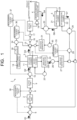
- FIG. 1 is a diagram illustrating the carbon dioxide conversion apparatus of the embodiment.
- a carbon dioxide conversion apparatus 1 illustrated in FIG. 1 includes a CO 2 capture part 2 which captures CO 2 from a carbon dioxide (CO 2 ) containing gas, a CO 2 electrolysis part 3 which converts CO 2 into carbon monoxide (CO) through electrolysis and reduction, an organic-substance synthesis part 4 which synthesizes an organic substance by using a gas containing the carbon monoxide (CO) and hydrogen (H 2 ) supplied from the CO 2 electrolysis part 3 as a feed gas, and an oxygen permeation-membrane partial oxidation part 5 which partially oxidizes a synthesis residual gas of the organic substance discharged from the organic-substance synthesis part 4 to produce CO and H 2 .
- CO 2 capture part 2 which captures CO 2 from a carbon dioxide (CO 2 ) containing gas
- CO 2 electrolysis part 3 which converts CO 2 into carbon monoxide (CO) through electrolysis and reduction
- an organic-substance synthesis part 4
- the CO 2 capture part 2 is configured to separate and capture CO 2 from an emission gas G1 containing CO 2 (CO 2 containing gas) emitted from a thermal power plant, a waste incineration plant, a steel plant, and the like, and supply a CO 2 gas G2 having an increased CO 2 concentration to the CO 2 electrolysis part 3.
- an emission gas G1 containing CO 2 (CO 2 containing gas) emitted from a thermal power plant, a waste incineration plant, a steel plant, and the like, and supply a CO 2 gas G2 having an increased CO 2 concentration to the CO 2 electrolysis part 3.
- the CO 2 capture part 2 can be constituted by applying, for example, a chemical absorption method of using a chemical absorption solution such as an amine aqueous solution, a physical absorption method of using a physical absorption solution such as methanol or a polyethylene glycol solution, a solid absorption method of using a solid absorbent such as an amine compound, a membrane separation method of using a CO 2 separation membrane, a physical adsorption method of using an inorganic substance such as zeolite as an adsorbent, a PSA (Pressure Swing Adsorption method), a TSA (Thermal Swing Adsorption method), or the like.
- a chemical absorption method of using a chemical absorption solution such as an amine aqueous solution
- a physical absorption method of using a physical absorption solution such as methanol or a polyethylene glycol solution
- a solid absorption method of using a solid absorbent such as an amine compound
- a membrane separation method of using a CO 2 separation membrane
- the chemical absorption method and a chemical absorber which use the amine aqueous solution can supply the emission gas G1 to an absorption tower in which the amine aqueous solution is sprayed, and heat the amine aqueous solution containing the absorbed CO 2 in a regeneration tower to capture CO 2 emitted from the amine aqueous solution.
- the capture method and device of CO 2 applied to the CO 2 capture part 2 are not particularly limited, and various methods and devices which allow the capture of CO 2 from the emission gas G1 can be applied.
- the CO 2 capture part 2 can receive the CO 2 containing gas G1 via a first flow rate regulating valve 6 and a gas mixer 7.
- the CO 2 capture part 2 is connected to a cathode chamber (reducing part) 11 of the CO 2 electrolysis part 3 via a first flowmeter 8, a first buffer tank 9, and a second flow rate regulating valve 10.
- the CO 2 capture part 2 is configured to supply a CO 2 gas G2 to the cathode chamber 11 via these components (8, 9, 10).
- the CO 2 electrolysis part 3 is a CO 2 electrolysis device having an electrolysis cell, and includes the cathode chamber (reducing part) 11 and an anode chamber (oxidizing part) 12.
- the cathode chamber 11 includes a reduction electrode (cathode)
- the anode chamber 12 includes an oxidation electrode (anode)
- an electrolytic solution is made to flow through at least the anode chamber 12.
- a CO 2 gas is made to flow through the cathode chamber 11.
- Examples of the electrolytic solution supplied into the anode chamber 12, include a solution using water (H 2 O), and an aqueous solution containing an optional electrolyte.
- Examples of the aqueous solution containing the electrolyte include an aqueous solution containing at least one ion selected from a phosphate ion (PO 4 2- ), a borate ion (BO 3 3- ), a sodium ion (Na + ), a potassium ion (K + ), a calcium ion (Ca 2+ ), a lithium ion (Li + ), a cesium ion (Cs + ), a magnesium ion (Mg 2+ ), a chloride ion (Cl - ), a hydrogen carbonate ion (HCO 3 - ), a carbonate ion (CO 3 2- ), and a hydroxide ion (OH - ).
- Examples of the electrolytic solution include an alkaline aqueous solution containing at least one dissolved compound selected from KOH, KHCO 3 , and K 2 CO 3 .
- the cathode chamber 11 can receive the CO 2 gas G2 captured in the CO 2 capture part 2.
- the cathode chamber 11 has a gas flow path facing a non-illustrated reduction electrode, and the CO 2 gas is supplied to the gas flow path.
- the anode chamber 12 has a liquid flow path facing a non-illustrated oxidation electrode, for example, and the electrolytic solution is supplied to such a liquid flow path.
- the cathode chamber 11 and the anode chamber 12 are separated by a diaphragm 13 capable of moving at least one ion selected from a hydrogen ion (H + ), a hydroxide ion (OH - ), a carbonate ion (CO 3 2- ), and a hydrogen carbonate ion (HCO 3 - ).
- a diaphragm 13 capable of moving at least one ion selected from a hydrogen ion (H + ), a hydroxide ion (OH - ), a carbonate ion (CO 3 2- ), and a hydrogen carbonate ion (HCO 3 - ).
- Examples of the diaphragm 13 include an ion exchange membrane.
- the CO 2 electrolysis part 3 (the CO 2 electrolysis device having the electrolysis cell) may have a single electrolysis cell or a structure in which electrolysis cells are arranged and connected in a plane direction, or may have a stack structure in which a plurality of the electrolysis cells
- Each of the reduction electrode and the oxidation electrode of the CO 2 electrolysis part 3 is connected to a direct-current power supply 14.
- the CO 2 electrolysis part 3 can perform the following electrolytic reaction in response to the supply of a direct current from the direct-current power supply 14 to the reduction electrode and the oxidation electrode. That is, the cathode chamber 11 and the anode chamber 12 of the CO 2 electrolysis part 3, can perform the following reactions.
- the cathode chamber 11 can perform the following electrolytic reaction and the following CO 2 reduction reaction presented by the following formula (1).
- the cathode chamber 11 can perform the reduction reaction of CO 2 to produce CO and a carbonate ion (CO 3 2- ). 2CO 2 + 2e - ⁇ CO + CO 3 2- ... (1)
- the carbonate ion (CO 3 2- ) produced in the cathode chamber 11 moves to the anode chamber 12 via the diaphragm 13.
- the anode chamber 12 can perform an oxidation reaction of the carbonate ion (CO 3 2- ), which is produced in the cathode chamber 11 and moved via the diaphragm 13, to produce CO 2 and O 2 , as presented in the following formula (2).
- the cathode chamber 11 can perform an electrolytic reaction of H 2 O in the electrolytic solution to produce hydrogen (H 2 ) and a hydroxide ion (OH - ), as presented in the following formula (3).
- the produced hydrogen ion (H + ) move to the cathode chamber 11 via the diaphragm 13.
- the hydrogen ion (H + ) reach the cathode chamber 11, and in the cathode chamber 11 which electrons (e - ) reach through an external circuit, hydrogen is produced by a reaction presented in the following formula (6). 4H + + 4e - ⁇ 2H 2 ... (6)
- the cathode chamber 11 can perform the CO 2 reduction reaction presented in the formula (1) to produce CO, and perform the H 2 O electrolytic reaction presented in the formula (3) and the reaction presented in the formula (6) to produce H 2 .
- CO and/or H 2 produced in the cathode chamber 11 are/is discharged from the cathode chamber 11 with unreacted CO 2 and saturated steam.
- a mixed gas (first gas) G3, discharged from the cathode chamber 11, containing CO and/or H 2 and/or CO 2 is subjected to a non-illustrated separation of condensed water through cooling, and thereafter supplied to the organic-substance synthesis part 4 as a part of the feed gas for a synthesis reaction of the organic substance.
- the cathode chamber 11 is connected to the organic-substance synthesis part 4 via a mixer 15, a CO/H 2 concentration meter 16, a second flowmeter 17, a second buffer tank 18, and a compressor 19.
- the mixed gas G3 is fed to the second buffer tank 18, and pressurized to a predetermined pressure by the compressor 19, and thereafter fed to the organic-substance synthesis part 4.
- a CO 2 separation part which separates and captures CO 2 from the mixed gas G3 may be provided between the cathode chamber 11 and the organic-substance synthesis part 4 (for example, between the cathode chamber 11 and the mixer 15).
- the CO 2 separated and captured here is fed to the cathode chamber 11 again.
- the organic-substance synthesis part 4 received the mixed gas containing CO and/or H 2 , can perform at least one reaction selected from a synthesis reaction of an organic substance using, for example, a Fischer-Tropsch synthesis reaction, for example, a reaction of synthesizing hydrocarbon, alcohol, other organic substances, or the like.
- Examples of the organic substance synthesized in the organic-substance synthesis part 4, include a carbon-containing liquid fuel.
- the product of the organic-substance synthesis part 4 (organic substance) is discharged from the organic-substance synthesis part 4, and fed to, for example, a separately installed storage facility such as a tank (not illustrated). From the organic-substance synthesis part 4, a synthesis residual gas G4 of the organic substance is discharged.
- the synthesis residual gas G4 contains an unnecessary product of lower hydrocarbon such as remaining CO, H 2 , CO 2 , or methane (CH 4 ), or the like.
- Such a synthesis residual gas G4 discharged from the organic-substance synthesis part 4 is subjected to an increase in temperature by a regenerative heat exchanger 20, and thereafter fed to a partial oxidation chamber 21 of the oxygen permeation-membrane partial oxidation part 5.
- the oxygen permeation-membrane partial oxidation part 5 is constituted by the partial oxidation chamber 21, an oxygen removal chamber 22, and an oxygen permeation membrane 23 disposed between them.
- the anode chamber 12 of the CO 2 electrolysis part 3 can perform the oxidation of a carbonate ion (CO 3 2- ) and a hydroxide ion (OH - ) to produce oxygen (O 2 ) and carbon dioxide (CO 2 ), as presented in the formula (2) and the formula (4),.
- a gas containing the O 2 and CO 2 produced in the anode chamber 12 (O 2 -CO 2 containing gas/second gas) is discharged from the anode chamber 12 with the electrolytic solution.
- the electrolytic solution containing the O 2 -CO 2 containing gas is fed to a gas/liquid separator 24, and the O 2 -CO 2 containing gas is separated from the electrolytic solution.
- the electrolytic solution separated by the gas/liquid separator 24 is cooled to a predetermined temperature by a cooler 25, and thereafter returned to the anode chamber 12.
- An O 2 -CO 2 containing gas G5 separated by the gas/liquid separator 24 contains CO 2 having a relatively high concentration in which a CO 2 concentration is 30 to 60 vol%, and thus emitting the O 2 -CO 2 containing gas G5 as it is into the air prevents efficient use of CO 2 , and fails to prevent global warming due to CO 2 , or the like.
- the O 2 -CO 2 containing gas G5 contains a relatively large amount of O 2 , and thus feeding the O 2 -CO 2 containing gas G5 as it is to the cathode chamber 11 lowers an operation and a function of the CO 2 electrolysis part 3.
- the O 2 -CO 2 containing gas G5 discharged from the anode chamber 12 of the CO 2 electrolysis part 3 and separated and captured by the gas/liquid separator 24 is fed to the oxygen removal chamber 22 of the oxygen permeation-membrane partial oxidation part 5.
- the O 2 -CO 2 containing gas G5 is fed to the oxygen removal chamber 22 via a cooler 26, a gas/liquid separator 27, a third flow rate regulating valve 28, and a regenerative heat exchanger 29.
- the O 2 -CO 2 containing gas G5 is cooled to a predetermined temperature by the cooler 26, subjected to a separation of condensed water by the gas/liquid separator 27 and an increase in temperature by the regenerative heat exchanger 29, and thereafter fed to the oxygen removal chamber 22.
- the oxygen permeation-membrane partial oxidation part 5 includes the partial oxidation chamber 21, the oxygen removal chamber 22, and the oxygen permeation membrane 23 disposed to separate them.
- the solid oxide electrolyte layer is an ion conductor passing ions such as oxygen ions, but not passing gas.
- solid oxide electrolyte layer for example, stabilized zirconia solid-dissolved with an oxide of a rare-earth element such as Y, Sc, Ce, Gd, or Sm used as a stabilizer, typically, yttria-stabilized zirconia (YSZ), ceria-stabilized zirconia (CSZ), or a composite of them is used.
- a rare-earth element such as Y, Sc, Ce, Gd, or Sm
- YSZ yttria-stabilized zirconia
- CSZ ceria-stabilized zirconia
- the oxygen permeation-membrane partial oxidation part 5 has a structure in which the partial oxidation chamber 21 as a first electrode chamber having a first electrode and the oxygen removal chamber 22 as a second electrode chamber having a second electrode are separated by the oxygen permeation membrane 23 formed of the solid oxide electrolyte layer or the like.
- the two electrodes are directly connected to be shorted therebetween, for example.
- the oxygen removal chamber 22 as the second electrode chamber is responsible for the conversion of oxygen molecules (O 2 ) into oxygen ions (O 2- ).
- the partial oxidation chamber 21 as the first electrode chamber is responsible for the conversion of oxygen ions (O 2- ) into oxygen molecules (O 2 ), and responsible for partial oxidation of the lower hydrocarbon such as methane (CH 4 ).
- the O 2 -CO 2 containing gas G5 discharged from the anode chamber 12 of the CO 2 electrolysis part 3 is supplied to the oxygen removal chamber 22.
- O 2 in the O 2 -CO 2 containing gas G5 is converted into oxygen ions (O 2- ), as presented in the following formula (7).
- the oxygen ions (O 2- ) converted in the oxygen removal chamber 22 are fed to the partial oxidation chamber 21 via the oxygen permeation membrane 23.
- the oxygen ions (O 2- ) fed to the partial oxidation chamber 21 are converted into an oxygen molecule (O 2 ), as presented in the following formula (8). 2O 2- ⁇ O 2 + 4e - ... (8)
- the partial oxidation chamber 21 can partially oxidize an oxidizable substance (substance to be oxidized) such as methane (CH 4 ) contained in the synthesis residual gas G4 to convert the oxidizable substance into CO and H 2 , as presented in the following formula (9).
- the partial oxidation chamber 21 can produce a gas containing CO and H 2 (CO-H 2 containing gas/third gas).
- the partial oxidation indicates a reaction in which in the oxidation of the lower hydrocarbon such as, for example, methane (CH 4 ), as presented in the formula (9), without oxidation to stable CO 2 , C is partially oxidized to produce H 2 -rich CO (partial oxidation state of C).
- an oxidizable substance such as methane (CH 4 ) contained in the synthesis residual gas G4 to convert the oxidizable substance into CO and H 2 , as presented in the following formula (9).
- the partial oxidation chamber 21 can produce a gas containing CO and H 2 (
- the oxygen permeation-membrane partial oxidation part 5 may include an oxygen ion-conducting electrolysis device or an oxygen ion-conducting fuel cell.
- the oxygen ion-conducting electrolysis device can include, for example, a solid oxide electrolysis cell (SOEC).
- SOEC includes a hydrogen electrode chamber, an oxygen electrode chamber, and an oxygen permeation membrane disposed to isolate them.
- a hydrogen electrode (cathode) disposed in the hydrogen electrode chamber and an oxygen electrode (anode) disposed in the oxygen electrode chamber are connected to a power supply.
- a solid oxide fuel cell SOFC
- the SOFC includes a fuel electrode chamber, an air electrode chamber, and an oxygen permeation membrane disposed to isolate them.
- the total amount of the O 2 -CO 2 containing gas discharged from the anode chamber 12 of the CO 2 electrolysis part 3 is supplied to the reduction electrode of the SOFC or the SOEC.
- a CO concentration of a discharge gas from the oxidation electrode of the SOFC or the SOEC may be regulated.
- the reduction electrode of the SOFC or the SOEC can perform a reaction presented in the following formula (11).
- the oxidation electrode of the SOFC or the SOEC can perform reactions presented in the following formula (12) and formula (13).
- a gas G6 containing CO and H 2 (CO-H 2 containing gas (third gas)) is discharged.
- the CO-H 2 containing gas G6 is used as a part of a feed gas in the organic-substance synthesis part 4, and thus fed to the mixer 15 via the regenerative heat exchanger 20, a cooler 30, a gas/liquid separator 31, and a CO concentration meter 32.
- the CO-H 2 containing gas G6 is cooled by the regenerative heat exchanger 20 and the cooler 30, subjected to a removal of condensed water by the gas/liquid separator 31, and thereafter fed to the second buffer tank 18 via the mixer 15.
- the CO-H 2 containing gas G6 is fed from the second buffer tank 18 to the compressor 19 in a mixed state with the CO-H 2 containing gas G3, and pressurized to a predetermined pressure by the compressor 19, and thereafter fed to the organic-substance synthesis part 4.
- an O 2 -CO 2 containing gas whose oxygen concentration is lowered (low-concentration O 2 -CO 2 containing gas) G7 is discharged.
- the O 2 -CO 2 containing gas may have an oxygen concentration lower than an oxygen concentration of the CO 2 gas G2.
- the low-concentration O 2 -CO 2 containing gas G7 contains CO 2 in a relatively high concentration, and is thus subjected to an increase in temperature by the regenerative heat exchanger 29 to be thereafter returned to the CO 2 capture part 2 for reuse.
- the low-concentration O 2 -CO 2 containing gas G7 contains a certain degree of O 2 despite lowering its oxygen concentration.
- the low-concentration O 2 -CO 2 containing gas G7 is returned to the CO 2 capture part 2, subjected to separation and capture of CO 2 in the CO 2 capture part 2, and fed to the cathode chamber 11 of the CO 2 electrolysis part 3 as the CO 2 gas G2 whose CO 2 concentration is increased, to be reused.
- the O 2 -CO 2 containing gas G7 having a low O 2 concentration allows, for example, a reduction in oxygen degradation of the amine aqueous solution (amine absorption solution) used for the CO 2 capture part 2.
- a CO concentration in the CO-H 2 containing gas G6 produced in the partial oxidation chamber 21 of the oxygen permeation-membrane partial oxidation part 5 varies depending on a flow rate of the O 2 -CO 2 containing gas G5 supplied to the oxygen removal chamber 22, or the like.
- the CO concentration in the CO-H 2 containing gas G6 is measured by the CO concentration meter 32 provided on a downstream side of the partial oxidation chamber 21 and the gas/liquid separator 31, and the flow rate of the O 2 -CO 2 containing gas G5 is controlled based on the measured CO concentration by the third flow rate regulating valve 28. This allows the CO concentration in the gas G6 to increase and a CO amount in the feed gas in the organic-substance synthesis part 4 to increase.
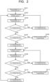
- a concrete flow rate regulation method for the CO concentration in the CO-H 2 containing gas G6 is as illustrated in FIG. 2 , for example.
- a CO concentration 1 in the CO-H 2 containing gas G6 is measured (S101), and the measurement data of the CO concentration 1 is sent to a first measurement control part 33.
- an opening degree signal 1 to increase an opening degree of the third flow rate regulating valve 28 is sent from the first measurement control part 33 to the third flow rate regulating valve 28 (S102).
- a CO concentration 2 in the gas G6 is measured (S103), and whether the CO concentration 2 is higher than the CO concentration 1 (CO concentration 1 ⁇ CO concentration 2) is determined (S104).
- the opening degree signal 1 of the third flow rate regulating valve 28 is increased (S102).
- the measurement of the CO concentration 2 in the gas G6 (S103) and the determination of whether the CO concentration 2 is higher than the CO concentration 1 (S104) are performed.
- the CO concentration 2 is higher than the CO concentration 1 (yes)
- the opening degree signal 1 of the third flow rate regulating valve 28 is maintained (S106).
- the opening degree signal 1 to decrease the opening degree of the third flow rate regulating valve 28 is sent from the first measurement control part 33 to the third flow rate regulating valve 28 (S107).
- the CO concentration 2 in the gas G6 is measured (S108), and whether the CO concentration 2 is higher than the CO concentration 1 (CO concentration 1 ⁇ CO concentration 2) is determined (S109).
- the opening degree signal 1 of the third flow rate regulating valve 28 is decreased (S107).
- the measurement of the CO concentration 2 in the gas G6 (S108) and the determination of whether the CO concentration 2 is higher than the CO concentration 1 (S109) are performed.
- the CO concentration 2 is higher than the CO concentration 1 (yes)
- the opening degree signal 1 of the third flow rate regulating valve 28 is maintained (S111).
- the opening degree signal 1 to increase the opening degree of the third flow rate regulating valve 28 is sent from the first measurement control part 33 to the third flow rate regulating valve 28 (S102). This manner increases the CO concentration in the gas G7, thereby allowing an increase in the CO amount in the feed gas in the organic-substance synthesis part 4.
- a supply part of H 2 (H 2 source) 35 is connected to the mixer 15 via a fourth flow rate regulating valve 34. Supplying H 2 from the H 2 source 35 to the CO-H 2 containing gas allows the regulation of the CO/H 2 ratio of the CO-H 2 containing gas to be supplied to the organic-substance synthesis part 4 as the feed gas.
- a concrete flow rate regulation method for the CO/H 2 ratio in the CO-H 2 containing gas is as illustrated in FIG. 3 , for example.
- the measurement of the CO concentration (S201) and the measurement of the H 2 concentration (S202) in the CO-H 2 containing gas are performed, and their measurement data is sent to a second measurement control part 36.
- the CO/H 2 ratio is found from the measurement data (S203).
- a value of [CO/H 2 ratio - set value] is found, and whether the value of [CO/H 2 ratio - set value] exceeds 0 is determined (S204).
- an opening degree signal 2 of the fourth flow rate regulating valve 34 is increased (S205).
- a flow rate of the CO-H 2 containing gas supplied to the organic-substance synthesis part 4 as the feed gas is also affected by a flow rate of the CO-H 2 containing gas G3 produced in the cathode chamber 11.
- the yield, the synthesis efficiency, and the like of the organic substance in the organic-substance synthesis part 4 are also affected by a supply amount of the feed gas.
- the flow rate of the CO-H 2 containing gas is measured by the second flowmeter 17 provided on an upstream side of the second buffer tank 18, and based on the measured flow rate of the gas, a flow rate of the CO 2 gas G2 to be supplied to the cathode chamber 11 is controlled, and a current value to be supplied from the direct-current power supply 14 to the CO 2 electrolysis part 3 is controlled. This allows the supply amount of the feed gas supplied to the organic-substance synthesis part 4 to approximate a set value.
- a concrete flow rate regulation method of the flow rate of the CO-H 2 containing gas G3 is as illustrated in FIG. 4 , for example
- a flow rate 1 of the CO-H 2 containing gas to be supplied to the organic-substance synthesis part 4 is measured by the second flowmeter 17 (S301), and this measurement data is sent to a third measurement control part 37.
- a value of [flow rate 1 - set value] is found from the measurement data, and whether the value of [flow rate 1 - set value] exceeds 0 is determined (S302).
- an opening degree signal 3 of the second flow rate regulating valve 10 and a signal of a current value (a current value signal) to be supplied from the direct-current power supply 14 are increased (S303).
- the flow rate of the CO-H 2 containing gas supplied to the organic-substance synthesis part 4 as the feed gas is also affected by the flow rate of the CO 2 gas G2 supplied to the cathode chamber 11.
- the flow rate of the CO 2 gas G2 is measured by the first flowmeter 8 provided on an upstream side of the first buffer tank 9, and based on the measured flow rate of the gas, a flow rate of the CO 2 containing gas G1 to be supplied to the CO 2 capture part 2 is controlled by the first flow rate regulating valve 6. This allows the supply amount of the feed gas supplied to the organic-substance synthesis part 4 to approximate the set value.
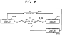
- a concrete flow rate regulation method of the flow rate of the CO 2 containing gas G1 is as illustrated in FIG. 5 , for example.
- a flow rate 2 of the CO 2 gas G2 to be supplied to the cathode chamber 11 is measured by the first flowmeter 8 (S401), and this measurement data is sent to a fourth measurement control part 38.
- a value of [flow rate 2 - set value] is found from the measurement data, and whether the value of [flow rate 2 - set value] exceeds 0 is determined (S402).
- an opening degree signal 4 of the first flow rate regulating valve 6 is increased (S403).
- the opening degree signal 4 of the first flow rate regulating valve 6 is decreased (S404).
- the value of [flow rate 2 - set value] is 0, the opening degree signal 4 of the first flow rate regulating valve 6 is maintained. Repeating such steps allows the flow rate 2 of the CO 2 gas G2 supplied to the cathode chamber 11 to approximate the set value.
- a methane flow rate may be calculated from a flow rate and a methane (CH 4 ) concentration of the synthesis residual gas G4 of the organic substance discharged from the organic-substance synthesis part 4, to control the flow rate of the O 2 -CO 2 containing gas G5 discharged from the anode chamber 12 based on the methane flow rate.
- a required flow rate of the O 2 -CO 2 containing gas G5 a correction of a water vapor content by using a gas temperature or a correction using by an oxygen concentration is also effective.
- a required oxygen amount can be calculated using characteristics of the oxygen permeation-membrane partial oxidation part 5.
- a hydrogen flow rate required for a predetermined CO/H 2 ratio may be calculated to supply hydrogen.
- a supply amount of the CO 2 containing gas may be controlled.
- a blower, a pump, a compressor, or the like may be appropriately disposed, and the flow of the fluid may be assisted by them. Further, a part of a discharge gas from the CO 2 capture part may be supplied for other uses such as underground storage, EOR, and CO 2 fixation (mineralization).
Landscapes
- Chemical & Material Sciences (AREA)
- Engineering & Computer Science (AREA)
- Chemical Kinetics & Catalysis (AREA)
- Organic Chemistry (AREA)
- Electrochemistry (AREA)
- General Chemical & Material Sciences (AREA)
- Metallurgy (AREA)
- Materials Engineering (AREA)
- Oil, Petroleum & Natural Gas (AREA)
- Environmental & Geological Engineering (AREA)
- Analytical Chemistry (AREA)
- Inorganic Chemistry (AREA)
- Health & Medical Sciences (AREA)
- Biomedical Technology (AREA)
- Combustion & Propulsion (AREA)
- Life Sciences & Earth Sciences (AREA)
- Sustainable Energy (AREA)
- Sustainable Development (AREA)
- Manufacturing & Machinery (AREA)
- Automation & Control Theory (AREA)
- Electrolytic Production Of Non-Metals, Compounds, Apparatuses Therefor (AREA)
Abstract
Description
- Embodiments relate to a carbon dioxide conversion apparatus and a carbon dioxide conversion method.
- Fossil fuels such as natural gas, coal, and petroleum is combusted to generate carbon dioxide (CO2) which is considered the main factor behind global warming due to a greenhouse effect, and thus the fossil fuels should be used less. Known example methods of reducing the carbon dioxide are performed by removing carbon dioxide from an exhaust gas from a carbon dioxide generation source to reduce an amount of the carbon dioxide emitted to the air and then chemically synthesizing a product from the carbon dioxide removed from the exhaust gas. An example method of the know example methods is performed by reducing carbon dioxide to produce carbon monoxide (CO), and synthesizing an organic substance from the produced carbon monoxide (CO) and hydrogen (H2), and the example method has developed. A part of a purge gas after producing the carbon monoxide is supplied to a carbon dioxide electrolysis device, and the remainder thereof is rendered harmless by air combustion to be emitted into the air. The carbon dioxide supplied to the carbon dioxide electrolysis device, which includes the carbon dioxide supplied for purging oxygen generated from the carbon dioxide electrolysis device and the carbon dioxide discharged from a combustion apparatus, is emitted to the air without being efficiently used. This inefficient use of the carbon dioxide in the carbon dioxide electrolysis device, demands to develop a carbon dioxide conversion apparatus and a carbon dioxide conversion method to allow the efficient use of the supplied carbon dioxide, the reduction in emission of the carbon dioxide into the air, and efficient production of the carbon monoxide of a reduction product of carbon dioxide.
-
-
FIG. 1 is a diagram illustrating a carbon dioxide conversion apparatus of an embodiment. -
FIG. 2 is a flowchart of controlling a carbon monoxide amount in a third gas in the carbon dioxide conversion apparatus illustrated inFIG. 1 . -
FIG. 3 is a flowchart of controlling a carbon monoxide/hydrogen ratio in the third gas in the carbon dioxide conversion apparatus illustrated inFIG. 1 . -
FIG. 4 is a flowchart of controlling a flow rate of a first gas in the carbon dioxide conversion apparatus illustrated inFIG. 1 . -
FIG. 5 is a flowchart of controlling a flow rate of a carbon dioxide containing gas in the carbon dioxide conversion apparatus illustrated inFIG. 1 . - Hereinafter, a carbon dioxide conversion apparatus of an embodiment will be described with reference to the drawings. In each embodiment presented below, substantially the same constituent parts are denoted by the same reference signs, and a description thereof may be partially omitted. The drawings are schematic, and the relation of the thickness and planar dimension, a thickness ratio among the parts, and so on may be different from actual ones. Note that a symbol of "~" in the following description indicates a range between an upper limit value and a lower limit value of respective numerical values. In this case, the range of the numerical values includes the upper limit value and the lower limit value.
- A carbon dioxide conversion apparatus of an embodiment includes:
a carbon dioxide capture part configured to capture a carbon dioxide from a carbon dioxide containing gas; a carbon dioxide electrolysis part having a cathode chamber configured to receive the carbon dioxide from the carbon dioxide capture part, and configured to reduce at least one selected from the group consisting of the carbon dioxide and water and produce a first gas containing at least one selected from the group consisting of carbon monoxide and hydrogen, and an anode chamber configured to oxidize an oxidizable substance and produce a second gas containing oxygen and carbon dioxide; a direct-current power supply configured to supply a direct current to the carbon dioxide electrolysis part; an organic-substance synthesis part configured to receive the first gas from the cathode chamber, and configured to synthesize an organic substance from a feed gas containing the first gas; a partial oxidation part having an oxygen removal chamber configured to receive the second gas from the anode chamber, and configured to ionize oxygen in the second gas to produce an oxygen ion a partial oxidation chamber configured to: receive a synthesis residual gas to be discharged from the organic-substance synthesis part, the synthesis residual gas containing the organic substance; partially oxidize the synthesis residual gas using the oxygen ion to be produced in the oxygen removal chamber and produce a third gas containing carbon monoxide and hydrogen; and supply the third gas as a part of the feed gas to the organic-substance synthesis part, and an oxygen permeation membrane provided between the oxygen removal chamber and the partial oxidation chamber; and a first control part configured to control an amount of the second gas to be supplied from the anode chamber to the oxygen removal chamber to increase an amount of carbon monoxide in the third gas to be produced in the partial oxidation chamber. -
FIG. 1 is a diagram illustrating the carbon dioxide conversion apparatus of the embodiment. A carbondioxide conversion apparatus 1 illustrated inFIG. 1 includes a CO2 capturepart 2 which captures CO2 from a carbon dioxide (CO2) containing gas, a CO2 electrolysis part 3 which converts CO2 into carbon monoxide (CO) through electrolysis and reduction, an organic-substance synthesis part 4 which synthesizes an organic substance by using a gas containing the carbon monoxide (CO) and hydrogen (H2) supplied from the CO2 electrolysis part 3 as a feed gas, and an oxygen permeation-membranepartial oxidation part 5 which partially oxidizes a synthesis residual gas of the organic substance discharged from the organic-substance synthesis part 4 to produce CO and H2. - The CO2 capture part 2 is configured to separate and capture CO2 from an emission gas G1 containing CO2 (CO2 containing gas) emitted from a thermal power plant, a waste incineration plant, a steel plant, and the like, and supply a CO2 gas G2 having an increased CO2 concentration to the CO2 electrolysis part 3. The CO2 capture
part 2 can be constituted by applying, for example, a chemical absorption method of using a chemical absorption solution such as an amine aqueous solution, a physical absorption method of using a physical absorption solution such as methanol or a polyethylene glycol solution, a solid absorption method of using a solid absorbent such as an amine compound, a membrane separation method of using a CO2 separation membrane, a physical adsorption method of using an inorganic substance such as zeolite as an adsorbent, a PSA (Pressure Swing Adsorption method), a TSA (Thermal Swing Adsorption method), or the like. For example, the chemical absorption method and a chemical absorber which use the amine aqueous solution can supply the emission gas G1 to an absorption tower in which the amine aqueous solution is sprayed, and heat the amine aqueous solution containing the absorbed CO2 in a regeneration tower to capture CO2 emitted from the amine aqueous solution. The capture method and device of CO2 applied to the CO2 capture part 2 are not particularly limited, and various methods and devices which allow the capture of CO2 from the emission gas G1 can be applied. - The CO2 capture
part 2 can receive the CO2 containing gas G1 via a first flowrate regulating valve 6 and a gas mixer 7. The CO2 capturepart 2 is connected to a cathode chamber (reducing part) 11 of the CO2 electrolysis part 3 via afirst flowmeter 8, afirst buffer tank 9, and a second flowrate regulating valve 10. The CO2 capture part 2 is configured to supply a CO2 gas G2 to thecathode chamber 11 via these components (8, 9, 10). - The CO2 electrolysis part 3 is a CO2 electrolysis device having an electrolysis cell, and includes the cathode chamber (reducing part) 11 and an anode chamber (oxidizing part) 12. The
cathode chamber 11 includes a reduction electrode (cathode), theanode chamber 12 includes an oxidation electrode (anode), and an electrolytic solution is made to flow through at least theanode chamber 12. A CO2 gas is made to flow through thecathode chamber 11. Examples of the electrolytic solution supplied into theanode chamber 12, include a solution using water (H2O), and an aqueous solution containing an optional electrolyte. Examples of the aqueous solution containing the electrolyte, include an aqueous solution containing at least one ion selected from a phosphate ion (PO4 2-), a borate ion (BO3 3-), a sodium ion (Na+), a potassium ion (K+), a calcium ion (Ca2+), a lithium ion (Li+), a cesium ion (Cs+), a magnesium ion (Mg2+), a chloride ion (Cl-), a hydrogen carbonate ion (HCO3 -), a carbonate ion (CO3 2-), and a hydroxide ion (OH-). Examples of the electrolytic solution include an alkaline aqueous solution containing at least one dissolved compound selected from KOH, KHCO3, and K2CO3. - The
cathode chamber 11 can receive the CO2 gas G2 captured in the CO2 capturepart 2. Thecathode chamber 11 has a gas flow path facing a non-illustrated reduction electrode, and the CO2 gas is supplied to the gas flow path. Theanode chamber 12 has a liquid flow path facing a non-illustrated oxidation electrode, for example, and the electrolytic solution is supplied to such a liquid flow path. Thecathode chamber 11 and theanode chamber 12 are separated by adiaphragm 13 capable of moving at least one ion selected from a hydrogen ion (H+), a hydroxide ion (OH-), a carbonate ion (CO3 2-), and a hydrogen carbonate ion (HCO3 -). Examples of thediaphragm 13 include an ion exchange membrane. The CO2 electrolysis part 3 (the CO2 electrolysis device having the electrolysis cell) may have a single electrolysis cell or a structure in which electrolysis cells are arranged and connected in a plane direction, or may have a stack structure in which a plurality of the electrolysis cells are stacked to be integrated. - Each of the reduction electrode and the oxidation electrode of the CO2 electrolysis part 3 is connected to a direct-
current power supply 14. The CO2 electrolysis part 3 can perform the following electrolytic reaction in response to the supply of a direct current from the direct-current power supply 14 to the reduction electrode and the oxidation electrode. That is, thecathode chamber 11 and theanode chamber 12 of the CO2 electrolysis part 3, can perform the following reactions. Thecathode chamber 11 can perform the following electrolytic reaction and the following CO2 reduction reaction presented by the following formula (1). Thecathode chamber 11 can perform the reduction reaction of CO2 to produce CO and a carbonate ion (CO3 2-).
2CO2 + 2e- → CO + CO3 2- ... (1)
- The carbonate ion (CO3 2-) produced in the
cathode chamber 11 moves to theanode chamber 12 via thediaphragm 13. Theanode chamber 12 can perform an oxidation reaction of the carbonate ion (CO3 2-), which is produced in thecathode chamber 11 and moved via thediaphragm 13, to produce CO2 and O2, as presented in the following formula (2).
CO3 2- → CO2 + 0.5O2 + 2e- ... (2)
- Moreover, the
cathode chamber 11 can perform an electrolytic reaction of H2O in the electrolytic solution to produce hydrogen (H2) and a hydroxide ion (OH-), as presented in the following formula (3).
2H2O + 2e- → H2 + 2OH- ... (3)
- The hydroxide ion (OH-) produced in the
cathode chamber 11 move to theanode chamber 12 via thediaphragm 13. Then, as presented in the following formula (4), water (H2O) and oxygen (O2) are produced in theanode chamber 12.
2OH- → 0.5O2 + H2O + 2e- ... (4)
- Further, in the
anode chamber 12, as presented in the following formula (5), water (H2O) in the electrolytic solution is electrolyzed to produce oxygen (O2) and a hydrogen ion (H+).
2H2O → 4H+ + Q2 + 4e- ... (5)
- The produced hydrogen ion (H+) move to the
cathode chamber 11 via thediaphragm 13. The hydrogen ion (H+) reach thecathode chamber 11, and in thecathode chamber 11 which electrons (e-) reach through an external circuit, hydrogen is produced by a reaction presented in the following formula (6).
4H+ + 4e- → 2H2 ... (6)
- The
cathode chamber 11 can perform the CO2 reduction reaction presented in the formula (1) to produce CO, and perform the H2O electrolytic reaction presented in the formula (3) and the reaction presented in the formula (6) to produce H2. CO and/or H2 produced in thecathode chamber 11 are/is discharged from thecathode chamber 11 with unreacted CO2 and saturated steam. A mixed gas (first gas) G3, discharged from thecathode chamber 11, containing CO and/or H2 and/or CO2 is subjected to a non-illustrated separation of condensed water through cooling, and thereafter supplied to the organic-substance synthesis part 4 as a part of the feed gas for a synthesis reaction of the organic substance. Thecathode chamber 11 is connected to the organic-substance synthesis part 4 via amixer 15, a CO/H2 concentration meter 16, asecond flowmeter 17, asecond buffer tank 18, and acompressor 19. The mixed gas G3 is fed to thesecond buffer tank 18, and pressurized to a predetermined pressure by thecompressor 19, and thereafter fed to the organic-substance synthesis part 4. Although illustration is omitted, a CO2 separation part which separates and captures CO2 from the mixed gas G3 may be provided between thecathode chamber 11 and the organic-substance synthesis part 4 (for example, between thecathode chamber 11 and the mixer 15). The CO2 separated and captured here is fed to thecathode chamber 11 again. - The organic-
substance synthesis part 4 received the mixed gas containing CO and/or H2, can perform at least one reaction selected from a synthesis reaction of an organic substance using, for example, a Fischer-Tropsch synthesis reaction, for example, a reaction of synthesizing hydrocarbon, alcohol, other organic substances, or the like. Examples of the organic substance synthesized in the organic-substance synthesis part 4, include a carbon-containing liquid fuel. The product of the organic-substance synthesis part 4 (organic substance) is discharged from the organic-substance synthesis part 4, and fed to, for example, a separately installed storage facility such as a tank (not illustrated). From the organic-substance synthesis part 4, a synthesis residual gas G4 of the organic substance is discharged. The synthesis residual gas G4 contains an unnecessary product of lower hydrocarbon such as remaining CO, H2, CO2, or methane (CH4), or the like. Such a synthesis residual gas G4 discharged from the organic-substance synthesis part 4 is subjected to an increase in temperature by aregenerative heat exchanger 20, and thereafter fed to apartial oxidation chamber 21 of the oxygen permeation-membranepartial oxidation part 5. The oxygen permeation-membranepartial oxidation part 5 is constituted by thepartial oxidation chamber 21, anoxygen removal chamber 22, and anoxygen permeation membrane 23 disposed between them. - Meanwhile, The
anode chamber 12 of the CO2 electrolysis part 3 can perform the oxidation of a carbonate ion (CO3 2-) and a hydroxide ion (OH-) to produce oxygen (O2) and carbon dioxide (CO2), as presented in the formula (2) and the formula (4),. A gas containing the O2 and CO2 produced in the anode chamber 12 (O2-CO2 containing gas/second gas) is discharged from theanode chamber 12 with the electrolytic solution. The electrolytic solution containing the O2-CO2 containing gas is fed to a gas/liquid separator 24, and the O2-CO2 containing gas is separated from the electrolytic solution. The electrolytic solution separated by the gas/liquid separator 24 is cooled to a predetermined temperature by a cooler 25, and thereafter returned to theanode chamber 12. - An O2-CO2 containing gas G5 separated by the gas/
liquid separator 24 contains CO2 having a relatively high concentration in which a CO2 concentration is 30 to 60 vol%, and thus emitting the O2-CO2 containing gas G5 as it is into the air prevents efficient use of CO2, and fails to prevent global warming due to CO2, or the like. Moreover, the O2-CO2 containing gas G5 contains a relatively large amount of O2, and thus feeding the O2-CO2 containing gas G5 as it is to thecathode chamber 11 lowers an operation and a function of the CO2 electrolysis part 3. Therefore, the O2-CO2 containing gas G5 discharged from theanode chamber 12 of the CO2 electrolysis part 3 and separated and captured by the gas/liquid separator 24 is fed to theoxygen removal chamber 22 of the oxygen permeation-membranepartial oxidation part 5. The O2-CO2 containing gas G5 is fed to theoxygen removal chamber 22 via a cooler 26, a gas/liquid separator 27, a third flowrate regulating valve 28, and aregenerative heat exchanger 29. The O2-CO2 containing gas G5 is cooled to a predetermined temperature by the cooler 26, subjected to a separation of condensed water by the gas/liquid separator 27 and an increase in temperature by theregenerative heat exchanger 29, and thereafter fed to theoxygen removal chamber 22. - The oxygen permeation-membrane
partial oxidation part 5 includes thepartial oxidation chamber 21, theoxygen removal chamber 22, and theoxygen permeation membrane 23 disposed to separate them. As theoxygen permeation membrane 23, a dense solid oxide electrolyte layer or the like is used. The solid oxide electrolyte layer is an ion conductor passing ions such as oxygen ions, but not passing gas. As the solid oxide electrolyte layer, for example, stabilized zirconia solid-dissolved with an oxide of a rare-earth element such as Y, Sc, Ce, Gd, or Sm used as a stabilizer, typically, yttria-stabilized zirconia (YSZ), ceria-stabilized zirconia (CSZ), or a composite of them is used. - The oxygen permeation-membrane
partial oxidation part 5 has a structure in which thepartial oxidation chamber 21 as a first electrode chamber having a first electrode and theoxygen removal chamber 22 as a second electrode chamber having a second electrode are separated by theoxygen permeation membrane 23 formed of the solid oxide electrolyte layer or the like. The two electrodes are directly connected to be shorted therebetween, for example. Theoxygen removal chamber 22 as the second electrode chamber is responsible for the conversion of oxygen molecules (O2) into oxygen ions (O2-). Thepartial oxidation chamber 21 as the first electrode chamber is responsible for the conversion of oxygen ions (O2-) into oxygen molecules (O2), and responsible for partial oxidation of the lower hydrocarbon such as methane (CH4). When a mixed conductor is used as theoxygen permeation membrane 23, the short caused by the direct connection between the electrodes (catalyst layers) is unnecessary. As the mixed conductor, perovskite such as (La1-xSrx)(Co1-yFey)O3, (Ba1-xSrx)(Co1-yFey)O3, (Pr1-xSrx)(Fe1-yAly)O3, or (La1-x-yBaxSry)(Fe1-zInz)O3, (Ce1-xREx)O2-MnFe2O4(RE = La, Pr, Sm, Gd), or a composite of them is used. - In the oxygen permeation-membrane
partial oxidation part 5 as described above, the O2-CO2 containing gas G5 discharged from theanode chamber 12 of the CO2 electrolysis part 3 is supplied to theoxygen removal chamber 22. In theoxygen removal chamber 22, O2 in the O2-CO2 containing gas G5 is converted into oxygen ions (O2-), as presented in the following formula (7).
O2 + 4e- - 2O2- ... (7)
- The oxygen ions (O2-) converted in the
oxygen removal chamber 22 are fed to thepartial oxidation chamber 21 via theoxygen permeation membrane 23. The oxygen ions (O2-) fed to thepartial oxidation chamber 21 are converted into an oxygen molecule (O2), as presented in the following formula (8).
2O2- → O2 + 4e- ... (8)
- The
partial oxidation chamber 21 can partially oxidize an oxidizable substance (substance to be oxidized) such as methane (CH4) contained in the synthesis residual gas G4 to convert the oxidizable substance into CO and H2, as presented in the following formula (9). Thepartial oxidation chamber 21 can produce a gas containing CO and H2 (CO-H2 containing gas/third gas). The partial oxidation indicates a reaction in which in the oxidation of the lower hydrocarbon such as, for example, methane (CH4), as presented in the formula (9), without oxidation to stable CO2, C is partially oxidized to produce H2-rich CO (partial oxidation state of C).
2CH4 + O2 → 2CO + 4H2 ... (9)
- Moreover, as presented in the following formula (10), CO2 and H2 are converted into CO and H2O by a reverse water shift reaction.
CO2 + H2 - CO + H2O ... (10)
- The oxygen permeation-membrane
partial oxidation part 5 may include an oxygen ion-conducting electrolysis device or an oxygen ion-conducting fuel cell. The oxygen ion-conducting electrolysis device can include, for example, a solid oxide electrolysis cell (SOEC). The SOEC includes a hydrogen electrode chamber, an oxygen electrode chamber, and an oxygen permeation membrane disposed to isolate them. A hydrogen electrode (cathode) disposed in the hydrogen electrode chamber and an oxygen electrode (anode) disposed in the oxygen electrode chamber are connected to a power supply. As the oxygen ion-conducting fuel cell, for example, a solid oxide fuel cell (SOFC) is used. The SOFC includes a fuel electrode chamber, an air electrode chamber, and an oxygen permeation membrane disposed to isolate them. - In this case, the total amount of the O2-CO2 containing gas discharged from the
anode chamber 12 of the CO2 electrolysis part 3 is supplied to the reduction electrode of the SOFC or the SOEC. By controlling an oxygen transfer amount from the reduction electrode of the SOFC or the SOEC to the oxidation electrode of the SOFC or the SOEC by using a current value, a CO concentration of a discharge gas from the oxidation electrode of the SOFC or the SOEC may be regulated. The reduction electrode of the SOFC or the SOEC, can perform a reaction presented in the following formula (11). The oxidation electrode of the SOFC or the SOEC, can perform reactions presented in the following formula (12) and formula (13). - Reduction electrode:
O2 + 2e- → 2O2- ... (11)
- Oxidation electrode:
2O2- → O2 + 2e- ... (12)
CH4 + O2 → CO + 2H2 ... (13)
- From the
partial oxidation chamber 21 of the oxygen permeation-membranepartial oxidation part 5, a gas G6 containing CO and H2 (CO-H2 containing gas (third gas)) is discharged. The CO-H2 containing gas G6 is used as a part of a feed gas in the organic-substance synthesis part 4, and thus fed to themixer 15 via theregenerative heat exchanger 20, a cooler 30, a gas/liquid separator 31, and aCO concentration meter 32. The CO-H2 containing gas G6 is cooled by theregenerative heat exchanger 20 and the cooler 30, subjected to a removal of condensed water by the gas/liquid separator 31, and thereafter fed to thesecond buffer tank 18 via themixer 15. The CO-H2 containing gas G6 is fed from thesecond buffer tank 18 to thecompressor 19 in a mixed state with the CO-H2 containing gas G3, and pressurized to a predetermined pressure by thecompressor 19, and thereafter fed to the organic-substance synthesis part 4. - From the
oxygen removal chamber 22 of the oxygen permeation-membranepartial oxidation part 5, an O2-CO2 containing gas whose oxygen concentration is lowered (low-concentration O2-CO2 containing gas) G7 is discharged. For example, the O2-CO2 containing gas may have an oxygen concentration lower than an oxygen concentration of the CO2 gas G2. The low-concentration O2-CO2 containing gas G7 contains CO2 in a relatively high concentration, and is thus subjected to an increase in temperature by theregenerative heat exchanger 29 to be thereafter returned to the CO2 capture part 2 for reuse. The low-concentration O2-CO2 containing gas G7 contains a certain degree of O2 despite lowering its oxygen concentration. Thus, the low-concentration O2-CO2 containing gas G7 is returned to the CO2 capture part 2, subjected to separation and capture of CO2 in the CO2 capture part 2, and fed to thecathode chamber 11 of the CO2 electrolysis part 3 as the CO2 gas G2 whose CO2 concentration is increased, to be reused. The O2-CO2 containing gas G7 having a low O2 concentration allows, for example, a reduction in oxygen degradation of the amine aqueous solution (amine absorption solution) used for the CO2 capture part 2. - As described above, feeding the synthesis residual gas G4 containing the unnecessary product such as methane (CH4), or the like to the
partial oxidation chamber 21 of the oxygen permeation-membranepartial oxidation part 5, and partially oxidizing methane (CH4) or the like to resynthesize CO and H2 allow efficient use of the synthesis residual gas G4 as a part of the feed gas in the organic-substance synthesis part 4. Further, the supply of the O2-CO2 containing gas G5 discharged from theanode chamber 12 of the CO2 electrolysis part 3 to theoxygen removal chamber 22 contributes to the above-described reproduction of CO and H2, and thereafter an oxygen concentration in the O2-CO2 containing gas G5 is lowered. This allows the return of the low-concentration O2-CO2 containing gas G7 whose CO2 concentration is increased to the CO2 capture part 2 and a promotion of the reuse of CO2. - A CO concentration in the CO-H2 containing gas G6 produced in the
partial oxidation chamber 21 of the oxygen permeation-membranepartial oxidation part 5 varies depending on a flow rate of the O2-CO2 containing gas G5 supplied to theoxygen removal chamber 22, or the like. Thus, the CO concentration in the CO-H2 containing gas G6 is measured by theCO concentration meter 32 provided on a downstream side of thepartial oxidation chamber 21 and the gas/liquid separator 31, and the flow rate of the O2-CO2 containing gas G5 is controlled based on the measured CO concentration by the third flowrate regulating valve 28. This allows the CO concentration in the gas G6 to increase and a CO amount in the feed gas in the organic-substance synthesis part 4 to increase. A concrete flow rate regulation method for the CO concentration in the CO-H2 containing gas G6 is as illustrated inFIG. 2 , for example. - As illustrated in
FIG. 2 , first, aCO concentration 1 in the CO-H2 containing gas G6 is measured (S101), and the measurement data of theCO concentration 1 is sent to a firstmeasurement control part 33. Next, anopening degree signal 1 to increase an opening degree of the third flowrate regulating valve 28 is sent from the firstmeasurement control part 33 to the third flow rate regulating valve 28 (S102). After increasing the opening degree of the third flowrate regulating valve 28, aCO concentration 2 in the gas G6 is measured (S103), and whether theCO concentration 2 is higher than the CO concentration 1 (CO concentration 1 < CO concentration 2) is determined (S104). When theCO concentration 2 is higher than the CO concentration 1 (yes), theopening degree signal 1 of the third flowrate regulating valve 28 is increased (S102). - Similarly, the measurement of the
CO concentration 2 in the gas G6 (S103) and the determination of whether theCO concentration 2 is higher than the CO concentration 1 (S104) are performed. When theCO concentration 2 is higher than the CO concentration 1 (yes), the above-described steps are performed, and when theCO concentration 2 is not higher than the CO concentration 1 (no), whether theCO concentration 2 is roughly equal to the CO concentration 1 (CO concentration 1 = CO concentration 2) is determined (S105). When theCO concentration 2 is roughly equal to the CO concentration 1 (yes), theopening degree signal 1 of the third flowrate regulating valve 28 is maintained (S106). When theCO concentration 2 is not roughly equal to the CO concentration 1 (no), theopening degree signal 1 to decrease the opening degree of the third flowrate regulating valve 28 is sent from the firstmeasurement control part 33 to the third flow rate regulating valve 28 (S107). - Next, the
CO concentration 2 in the gas G6 is measured (S108), and whether theCO concentration 2 is higher than the CO concentration 1 (CO concentration 1 < CO concentration 2) is determined (S109). When theCO concentration 2 is higher than the CO concentration 1 (yes), theopening degree signal 1 of the third flowrate regulating valve 28 is decreased (S107). Similarly, the measurement of theCO concentration 2 in the gas G6 (S108) and the determination of whether theCO concentration 2 is higher than the CO concentration 1 (S109) are performed. When theCO concentration 2 is higher than the CO concentration 1 (yes), the above-described steps are performed, and when theCO concentration 2 is not higher than the CO concentration 1 (no), whether theCO concentration 2 is roughly equal to the CO concentration 1 (CO concentration 1 = CO concentration 2) is determined (S110). When theCO concentration 2 is roughly equal to the CO concentration 1 (yes), theopening degree signal 1 of the third flowrate regulating valve 28 is maintained (S111). When theCO concentration 2 is not roughly equal to the CO concentration 1 (no), theopening degree signal 1 to increase the opening degree of the third flowrate regulating valve 28 is sent from the firstmeasurement control part 33 to the third flow rate regulating valve 28 (S102). This manner increases the CO concentration in the gas G7, thereby allowing an increase in the CO amount in the feed gas in the organic-substance synthesis part 4. - In the CO-H2 containing gas supplied to the organic-
substance synthesis part 4 as the feed gas, increasing the CO concentration in the CO-H2 containing gas G6 produced in thepartial oxidation chamber 21 as described above causes the possibility of an insufficient H2 amount in the feed gas and a decrease in CO/H2 ratio. Thus, a supply part of H2 (H2 source) 35 is connected to themixer 15 via a fourth flowrate regulating valve 34. Supplying H2 from the H2 source 35 to the CO-H2 containing gas allows the regulation of the CO/H2 ratio of the CO-H2 containing gas to be supplied to the organic-substance synthesis part 4 as the feed gas. However, even though H2 is uniformly added from the H2 source 35 to the CO-H2 containing gas, a set value of the CO/H2 ratio cannot be maintained. Thus, the CO concentration and the H2 concentration are measured by the CO/H2 concentration meter 16 provided on a downstream side of thesecond buffer tank 18, and based on the measured CO concentration and H2 concentration, a H2 addition amount from the H2 source 35 is controlled by the fourth flowrate regulating valve 34. This allows the CO/H2 ratio of the CO-H2 containing gas to approximate the set value, and a yield and synthesis efficiency of the organic-substance synthesis part 4 to increase. A concrete flow rate regulation method for the CO/H2 ratio in the CO-H2 containing gas is as illustrated inFIG. 3 , for example. - As illustrated in
FIG. 3 , first, the measurement of the CO concentration (S201) and the measurement of the H2 concentration (S202) in the CO-H2 containing gas are performed, and their measurement data is sent to a secondmeasurement control part 36. In the secondmeasurement control part 36, the CO/H2 ratio is found from the measurement data (S203). Moreover, a value of [CO/H2 ratio - set value] is found, and whether the value of [CO/H2 ratio - set value] exceeds 0 is determined (S204). When the value of [CO/H2 ratio - set value] exceeds 0, anopening degree signal 2 of the fourth flowrate regulating valve 34 is increased (S205). When the value of [CO/H2 ratio - set value] is less than 0, theopening degree signal 2 of the fourth flowrate regulating valve 34 is decreased (S205). When the value of [CO/H2 ratio - set value] is 0, theopening degree signal 2 of the fourth flowrate regulating valve 34 is maintained. Repeating such steps allows the CO/H2 ratio of the CO-H2 containing gas to approximate the set value. - A flow rate of the CO-H2 containing gas supplied to the organic-
substance synthesis part 4 as the feed gas is also affected by a flow rate of the CO-H2 containing gas G3 produced in thecathode chamber 11. The yield, the synthesis efficiency, and the like of the organic substance in the organic-substance synthesis part 4 are also affected by a supply amount of the feed gas. Thus, the flow rate of the CO-H2 containing gas is measured by thesecond flowmeter 17 provided on an upstream side of thesecond buffer tank 18, and based on the measured flow rate of the gas, a flow rate of the CO2 gas G2 to be supplied to thecathode chamber 11 is controlled, and a current value to be supplied from the direct-current power supply 14 to the CO2 electrolysis part 3 is controlled. This allows the supply amount of the feed gas supplied to the organic-substance synthesis part 4 to approximate a set value. A concrete flow rate regulation method of the flow rate of the CO-H2 containing gas G3 is as illustrated inFIG. 4 , for example. - As illustrated in
FIG. 4 , first, aflow rate 1 of the CO-H2 containing gas to be supplied to the organic-substance synthesis part 4 is measured by the second flowmeter 17 (S301), and this measurement data is sent to a thirdmeasurement control part 37. In the thirdmeasurement control part 37, a value of [flow rate 1 - set value] is found from the measurement data, and whether the value of [flow rate 1 - set value] exceeds 0 is determined (S302). When the value of [flow rate 1 - set value] exceeds 0, anopening degree signal 3 of the second flowrate regulating valve 10 and a signal of a current value (a current value signal) to be supplied from the direct-current power supply 14 are increased (S303). When the value of [flow rate 1 - set value] is less than 0, theopening degree signal 3 of the second flowrate regulating valve 10 and the signal of the current value to be supplied from the direct-current power supply 14 are decreased (S304). When the value of [flow rate 1 - set value] is 0, theopening degree signal 3 of the second flowrate regulating valve 10 and the signal of the current value to be supplied from the direct-current power supply 14 are maintained. Repeating such steps allows theflow rate 1 of the CO-H2 containing gas to approximate the set value. - Moreover, the flow rate of the CO-H2 containing gas supplied to the organic-
substance synthesis part 4 as the feed gas is also affected by the flow rate of the CO2 gas G2 supplied to thecathode chamber 11. Thus, the flow rate of the CO2 gas G2 is measured by thefirst flowmeter 8 provided on an upstream side of thefirst buffer tank 9, and based on the measured flow rate of the gas, a flow rate of the CO2 containing gas G1 to be supplied to the CO2 capture part 2 is controlled by the first flowrate regulating valve 6. This allows the supply amount of the feed gas supplied to the organic-substance synthesis part 4 to approximate the set value. A concrete flow rate regulation method of the flow rate of the CO2 containing gas G1 is as illustrated inFIG. 5 , for example. - As illustrated in
FIG. 5 , first, aflow rate 2 of the CO2 gas G2 to be supplied to thecathode chamber 11 is measured by the first flowmeter 8 (S401), and this measurement data is sent to a fourthmeasurement control part 38. In the fourthmeasurement control part 38, a value of [flow rate 2 - set value] is found from the measurement data, and whether the value of [flow rate 2 - set value] exceeds 0 is determined (S402). When the value of [flow rate 2 - set value] exceeds 0, anopening degree signal 4 of the first flowrate regulating valve 6 is increased (S403). When the value of [flow rate 2 - set value] is less than 0, theopening degree signal 4 of the first flowrate regulating valve 6 is decreased (S404). When the value of [flow rate 2 - set value] is 0, theopening degree signal 4 of the first flowrate regulating valve 6 is maintained. Repeating such steps allows theflow rate 2 of the CO2 gas G2 supplied to thecathode chamber 11 to approximate the set value. - In addition to the regulation of the gas concentration, the gas flow rate, and the like as described above, a methane flow rate may be calculated from a flow rate and a methane (CH4) concentration of the synthesis residual gas G4 of the organic substance discharged from the organic-
substance synthesis part 4, to control the flow rate of the O2-CO2 containing gas G5 discharged from theanode chamber 12 based on the methane flow rate. In a required flow rate of the O2-CO2 containing gas G5, a correction of a water vapor content by using a gas temperature or a correction using by an oxygen concentration is also effective. A required oxygen amount can be calculated using characteristics of the oxygen permeation-membranepartial oxidation part 5. Moreover, from a flow rate, a CO concentration, and a H2 concentration after mixing the CO and H2 containing gas G3 discharged from thecathode chamber 11 of the CO2 electrolysis part 3 and the CO and H2 containing gas G6 discharged from thepartial oxidation part 21 of the oxygen permeation-membranepartial oxidation part 5, a hydrogen flow rate required for a predetermined CO/H2 ratio may be calculated to supply hydrogen. - From a flow rate and a CO2 concentration after mixing a bypass flow of the O2-CO2 containing gas discharged from the
anode chamber 12 of the CO2 electrolysis part 3 and the low-concentration O2-CO2 containing gas discharged from the oxygen removal chamber of the oxygen permeation-membranepartial oxidation part 5, and a CO2 concentration of the CO2 containing gas, a supply amount of the CO2 containing gas may be controlled. - Note that though not described and illustrated in the above-described embodiment and
FIG. 1 , a blower, a pump, a compressor, or the like may be appropriately disposed, and the flow of the fluid may be assisted by them. Further, a part of a discharge gas from the CO2 capture part may be supplied for other uses such as underground storage, EOR, and CO2 fixation (mineralization). - Note that the configurations of the above-described embodiments are applicable in combination with each other, and parts thereof are also replaceable. While certain embodiments of the present invention have been described above, these embodiments have been presented by way of example only, and are not intended to limit the scope of the invention. Indeed these embodiments described herein may be embodied in a variety of other forms; furthermore, various omissions, substitutions, and changes in the form of the embodiments described herein may be made without departing from the spirit of the inventions. The accompanying claims and their equivalents are intended to cover such forms or modifications as would fall within the scope and spirit of the inventions.
Claims (7)
- A carbon dioxide conversion apparatus comprising:a carbon dioxide capture part configured to capture a carbon dioxide from a carbon dioxide containing gas;a carbon dioxide electrolysis part havinga cathode chamber configured to receive the carbon dioxide from the carbon dioxide capture part, and configured to reduce at least one selected from the group consisting of the carbon dioxide and water and produce a first gas containing at least one selected from the group consisting of carbon monoxide and hydrogen, andan anode chamber configured to oxidize an oxidizable substance and produce a second gas containing oxygen and carbon dioxide;a direct-current power supply configured to supply a direct current to the carbon dioxide electrolysis part;an organic-substance synthesis part configured to receive the first gas from the cathode chamber, and configured to synthesize an organic substance from a feed gas containing the first gas;a partial oxidation part havingan oxygen removal chamber configured to receive the second gas from the anode chamber, and configured to ionize oxygen in the second gas to produce an oxygen ion,a partial oxidation chamber configured to:receive a synthesis residual gas to be discharged from the organic-substance synthesis part, the synthesis residual gas containing the organic substance;partially oxidize the synthesis residual gas using the oxygen ion to be produced in the oxygen removal chamber and produce a third gas containing carbon monoxide and hydrogen; andsupply the third gas as a part of the feed gas to the organic-substance synthesis part, andan oxygen permeation membrane provided between the oxygen removal chamber and the partial oxidation chamber; anda first control part configured to control an amount of the second gas to be supplied from the anode chamber to the oxygen removal chamber to increase an amount of carbon monoxide in the third gas to be produced in the partial oxidation chamber.
- The apparatus according to claim 1, further comprising:a hydrogen supply part configured to supply a hydrogen gas to the feed gas; anda second control part configured to control an amount of the hydrogen gas to be supplied from the hydrogen supply part to control a ratio of carbon monoxide and hydrogen in the feed gas.
- The apparatus according to claim 1, further comprising
a third control part configured to control an amount of carbon dioxide to be supplied to the cathode chamber and a value of the direct current to be supplied from the direct-current power supply to the carbon dioxide electrolysis part to control an amount of the feed gas to be supplied to the organic-substance synthesis part. - The apparatus according to claim 1, further comprising
a fourth control part configured to control an amount of the carbon dioxide containing gas to the carbon dioxide capture part to control an amount of carbon dioxide to be supplied from the carbon dioxide capture part to the cathode chamber. - The apparatus according to claim 1, wherein
the partial oxidation part is configured to discharge a carbon dioxide-containing residual gas, and supply the carbon dioxide-containing residual gas to the carbon dioxide capture part, the carbon dioxide-containing residual gas having an oxygen concentration lower than an oxygen concentration of the second gas. - The apparatus according to claim 1, wherein
the partial oxidation part includes an oxygen ion-conducting electrolysis device. - The apparatus according to claim 1, wherein
the partial oxidation part includes an oxygen ion-conducting fuel cell.
Applications Claiming Priority (1)
| Application Number | Priority Date | Filing Date | Title |
|---|---|---|---|
| JP2023034960A JP2024126545A (en) | 2023-03-07 | 2023-03-07 | Carbon dioxide conversion device and carbon dioxide conversion method |
Publications (2)
| Publication Number | Publication Date |
|---|---|
| EP4428265A2 true EP4428265A2 (en) | 2024-09-11 |
| EP4428265A3 EP4428265A3 (en) | 2024-12-18 |
Family
ID=89707932
Family Applications (1)
| Application Number | Title | Priority Date | Filing Date |
|---|---|---|---|
| EP24153380.1A Pending EP4428265A3 (en) | 2023-03-07 | 2024-01-23 | Carbon dioxide conversion apparatus |
Country Status (3)
| Country | Link |
|---|---|
| US (1) | US20240301567A1 (en) |
| EP (1) | EP4428265A3 (en) |
| JP (1) | JP2024126545A (en) |
Family Cites Families (7)
| Publication number | Priority date | Publication date | Assignee | Title |
|---|---|---|---|---|
| JP3801249B2 (en) * | 1996-01-22 | 2006-07-26 | 東燃ゼネラル石油株式会社 | Membrane reactor and hydrocarbon partial oxidation method using the same |
| JP4672120B2 (en) * | 2000-08-24 | 2011-04-20 | 三菱重工業株式会社 | Fuel cell device and method of operating fuel cell device. |
| JP2003168455A (en) * | 2001-11-29 | 2003-06-13 | Nissan Motor Co Ltd | Fuel cell system |
| GB2568564B (en) * | 2018-07-17 | 2020-01-01 | Omnagen Ltd | Carbon dioxide conversion using combined fuel cell and electrolysis cell |
| EP4048651A1 (en) * | 2019-12-20 | 2022-08-31 | Siemens Energy Global GmbH & Co. KG | Apparatus and method for utilizing off-gases from a power-to-x system |
| JP7297710B2 (en) * | 2020-03-23 | 2023-06-26 | 株式会社東芝 | carbon dioxide reactor |
| WO2022031726A2 (en) * | 2020-08-03 | 2022-02-10 | Opus 12 Incorporated | System and method for carbon dioxide reactor control |
-
2023
- 2023-03-07 JP JP2023034960A patent/JP2024126545A/en active Pending
-
2024
- 2024-01-22 US US18/418,724 patent/US20240301567A1/en active Pending
- 2024-01-23 EP EP24153380.1A patent/EP4428265A3/en active Pending
Also Published As
| Publication number | Publication date |
|---|---|
| US20240301567A1 (en) | 2024-09-12 |
| JP2024126545A (en) | 2024-09-20 |
| EP4428265A3 (en) | 2024-12-18 |
Similar Documents
| Publication | Publication Date | Title |
|---|---|---|
| US11710841B2 (en) | Reaction device and fuel cell power generation system | |
| US11888199B2 (en) | Operation of molten carbonate fuel cells with high electrolyte fill level | |
| JP6084314B1 (en) | Fuel cell system | |
| KR20200110501A (en) | Oxygen enrichment apparatus, solid oxide fuel cell with the same and operation method thereof | |
| US20240301567A1 (en) | Carbon dioxide conversion apparatus and carbon dioxide conversion method | |
| CN114976155A (en) | Hydrogen fuel cell system combining methanol reforming and solid oxide | |
| US8679436B2 (en) | Process for working up an exhaust gas from a system for producing hydroxylamine or hydroxylammonium salts | |
| US20240360568A1 (en) | Carbon monoxide production device, carbon dioxide electrolysis device, and carbon dioxide electrolysis method | |
| KR101972433B1 (en) | Fuel cell system | |
| US20250289716A1 (en) | Carbon dioxide capture and carbon resource utilization system, for fuel cell, using boil-off gas generated from liquefied natural gas | |
| JP7666869B2 (en) | Carbon Dioxide Treatment Equipment | |
| JP7830265B2 (en) | Carbon dioxide conversion device | |
| EP4427832A1 (en) | Carbon dioxide conversion apparatus and carbon dioxide conversion method | |
| JP4536391B2 (en) | Fuel cell power generation system and fuel cell module | |
| US20240318340A1 (en) | Carbon dioxide conversion device | |
| EP4517888A1 (en) | Carbon dioxide capture and carbon resource utilization system for fuel cell and method using same | |
| KR102491197B1 (en) | Fuel cell system comprising steam reforming reactor and dry reforming reactor | |
| US20240072339A1 (en) | Renewable energy integration with natural-gas based combined hydrogen and electricity production (chep) system and method | |
| JP2024027957A (en) | Carbon monoxide production equipment | |
| KR20160039108A (en) | Fuel Cell System with Pure Oxygen Process |
Legal Events
| Date | Code | Title | Description |
|---|---|---|---|
| PUAI | Public reference made under article 153(3) epc to a published international application that has entered the european phase |
Free format text: ORIGINAL CODE: 0009012 |
|
| STAA | Information on the status of an ep patent application or granted ep patent |
Free format text: STATUS: REQUEST FOR EXAMINATION WAS MADE |
|
| 17P | Request for examination filed |
Effective date: 20240123 |
|
| AK | Designated contracting states |
Kind code of ref document: A2 Designated state(s): AL AT BE BG CH CY CZ DE DK EE ES FI FR GB GR HR HU IE IS IT LI LT LU LV MC ME MK MT NL NO PL PT RO RS SE SI SK SM TR |
|
| PUAL | Search report despatched |
Free format text: ORIGINAL CODE: 0009013 |
|
| AK | Designated contracting states |
Kind code of ref document: A3 Designated state(s): AL AT BE BG CH CY CZ DE DK EE ES FI FR GB GR HR HU IE IS IT LI LT LU LV MC ME MK MT NL NO PL PT RO RS SE SI SK SM TR |
|
| RIC1 | Information provided on ipc code assigned before grant |
Ipc: H01M 8/00 20160101ALI20241111BHEP Ipc: C25B 15/08 20060101ALI20241111BHEP Ipc: C25B 15/02 20210101ALI20241111BHEP Ipc: C25B 1/23 20210101ALI20241111BHEP Ipc: C10G 2/00 20060101ALI20241111BHEP Ipc: C07C 29/151 20060101ALI20241111BHEP Ipc: B01D 53/00 20060101ALI20241111BHEP Ipc: C25B 1/04 20210101AFI20241111BHEP |