EP4428221A1 - Solution state measurement device - Google Patents
Solution state measurement device Download PDFInfo
- Publication number
- EP4428221A1 EP4428221A1 EP23855039.6A EP23855039A EP4428221A1 EP 4428221 A1 EP4428221 A1 EP 4428221A1 EP 23855039 A EP23855039 A EP 23855039A EP 4428221 A1 EP4428221 A1 EP 4428221A1
- Authority
- EP
- European Patent Office
- Prior art keywords
- support portion
- probe
- detecting
- mesh
- support
- Prior art date
- Legal status (The legal status is an assumption and is not a legal conclusion. Google has not performed a legal analysis and makes no representation as to the accuracy of the status listed.)
- Pending
Links
Images




Classifications
-
- C—CHEMISTRY; METALLURGY
- C12—BIOCHEMISTRY; BEER; SPIRITS; WINE; VINEGAR; MICROBIOLOGY; ENZYMOLOGY; MUTATION OR GENETIC ENGINEERING
- C12M—APPARATUS FOR ENZYMOLOGY OR MICROBIOLOGY; APPARATUS FOR CULTURING MICROORGANISMS FOR PRODUCING BIOMASS, FOR GROWING CELLS OR FOR OBTAINING FERMENTATION OR METABOLIC PRODUCTS, i.e. BIOREACTORS OR FERMENTERS
- C12M41/00—Means for regulation, monitoring, measurement or control, e.g. flow regulation
-
- G—PHYSICS
- G01—MEASURING; TESTING
- G01N—INVESTIGATING OR ANALYSING MATERIALS BY DETERMINING THEIR CHEMICAL OR PHYSICAL PROPERTIES
- G01N33/00—Investigating or analysing materials by specific methods not covered by groups G01N1/00 - G01N31/00
- G01N33/18—Water
- G01N33/1886—Water using probes, e.g. submersible probes, buoys
-
- C—CHEMISTRY; METALLURGY
- C12—BIOCHEMISTRY; BEER; SPIRITS; WINE; VINEGAR; MICROBIOLOGY; ENZYMOLOGY; MUTATION OR GENETIC ENGINEERING
- C12M—APPARATUS FOR ENZYMOLOGY OR MICROBIOLOGY; APPARATUS FOR CULTURING MICROORGANISMS FOR PRODUCING BIOMASS, FOR GROWING CELLS OR FOR OBTAINING FERMENTATION OR METABOLIC PRODUCTS, i.e. BIOREACTORS OR FERMENTERS
- C12M1/00—Apparatus for enzymology or microbiology
- C12M1/21—Froth suppressors
-
- C—CHEMISTRY; METALLURGY
- C12—BIOCHEMISTRY; BEER; SPIRITS; WINE; VINEGAR; MICROBIOLOGY; ENZYMOLOGY; MUTATION OR GENETIC ENGINEERING
- C12M—APPARATUS FOR ENZYMOLOGY OR MICROBIOLOGY; APPARATUS FOR CULTURING MICROORGANISMS FOR PRODUCING BIOMASS, FOR GROWING CELLS OR FOR OBTAINING FERMENTATION OR METABOLIC PRODUCTS, i.e. BIOREACTORS OR FERMENTERS
- C12M1/00—Apparatus for enzymology or microbiology
- C12M1/34—Measuring or testing with condition measuring or sensing means, e.g. colony counters
-
- C—CHEMISTRY; METALLURGY
- C12—BIOCHEMISTRY; BEER; SPIRITS; WINE; VINEGAR; MICROBIOLOGY; ENZYMOLOGY; MUTATION OR GENETIC ENGINEERING
- C12M—APPARATUS FOR ENZYMOLOGY OR MICROBIOLOGY; APPARATUS FOR CULTURING MICROORGANISMS FOR PRODUCING BIOMASS, FOR GROWING CELLS OR FOR OBTAINING FERMENTATION OR METABOLIC PRODUCTS, i.e. BIOREACTORS OR FERMENTERS
- C12M23/00—Constructional details, e.g. recesses, hinges
- C12M23/46—Means for fastening
-
- C—CHEMISTRY; METALLURGY
- C12—BIOCHEMISTRY; BEER; SPIRITS; WINE; VINEGAR; MICROBIOLOGY; ENZYMOLOGY; MUTATION OR GENETIC ENGINEERING
- C12M—APPARATUS FOR ENZYMOLOGY OR MICROBIOLOGY; APPARATUS FOR CULTURING MICROORGANISMS FOR PRODUCING BIOMASS, FOR GROWING CELLS OR FOR OBTAINING FERMENTATION OR METABOLIC PRODUCTS, i.e. BIOREACTORS OR FERMENTERS
- C12M29/00—Means for introduction, extraction or recirculation of materials, e.g. pumps
- C12M29/04—Filters; Permeable or porous membranes or plates, e.g. dialysis
-
- C—CHEMISTRY; METALLURGY
- C12—BIOCHEMISTRY; BEER; SPIRITS; WINE; VINEGAR; MICROBIOLOGY; ENZYMOLOGY; MUTATION OR GENETIC ENGINEERING
- C12M—APPARATUS FOR ENZYMOLOGY OR MICROBIOLOGY; APPARATUS FOR CULTURING MICROORGANISMS FOR PRODUCING BIOMASS, FOR GROWING CELLS OR FOR OBTAINING FERMENTATION OR METABOLIC PRODUCTS, i.e. BIOREACTORS OR FERMENTERS
- C12M41/00—Means for regulation, monitoring, measurement or control, e.g. flow regulation
- C12M41/46—Means for regulation, monitoring, measurement or control, e.g. flow regulation of cellular or enzymatic activity or functionality, e.g. cell viability
Definitions
- the present disclosure relates to a device for detecting a solution state, and more particularly, to a device for detecting a solution state which may include a mesh disposed in a path through which a solution is introduced into a probe for detecting the solution state to prevent a bubble from entering a detecting portion of the probe, thereby preventing an error from occurring in the detected solution state.
- 3-Hydropropionic Acid may be a platform compound that may be converted into many other useful chemicals, including acrylic acid, and thus may be widely applied to production of pigments, paints, fibers, or the like.
- the 3-HP may be a representative biodegradable material that may be produced by fermenting colon bacillus.
- the colon bacillus may be cultured and fermented in a culture fluid in a reactor.
- a spectrometer may be installed in this reactor to detect a concentration of the colon bacillus in the culture fluid in real time.
- various detection devices may be installed in the reactor to detect a state (e.g., concentration, capacitance, or inductance) of the culture fluid, thereby predicting a state of the colon bacillus. These detection devices may be typically configured to detect the state of the culture fluid flowing into the detecting portion in real time.
- An agitating device may also be disposed in the reactor for cultivating the colon bacillus.
- the agitating device may be configured to agitate the culture fluid and supply oxygen to the colon bacillus in the culture fluid.
- a bubble or the like may occur in the culture fluid, and the occurring bubble may be introduced into the detecting portion of the detection device along with the culture fluid.
- the state of the culture fluid detected by the detection device may not be uniform. That is, an error may occur in the state of the culture fluid detected by the detection device.
- the present disclosure attempts to provide a device for detecting a solution state which may include a mesh disposed in a path through which a solution is introduced into a probe for detecting the solution state to prevent a bubble from entering the probe.
- a device for detecting a solution state including: a probe including a detecting portion having at least one open surface to detect the solution state; a mesh disposed on a path through which a solution is introduced into the detecting portion; and a support portion disposed on an outside of the probe, and having an opening surrounding the at least one open surface of the detecting portion, wherein the opening defines the path through which the solution is introduced into the detecting portion, and the mesh is mounted in the opening of the support portion.
- An inner surface of the support portion may be spaced apart from an outer surface of the probe by a predetermined distance.
- the support portion may be detachably mounted on an outer surface of the probe through a fastening portion.
- the support portion may include first and second support portions spaced apart from each other by a predetermined distance, and the first and second support portions may be detachably assembled to each other for the mesh to be mounted at the predetermined distance between the first and second support portions.
- the first and second support portions may be screwed to each other.
- the second support portion may be inserted into the first support portion while being spaced apart from the first support portion by the predetermined distance, and a first thread portion may be formed on an inner surface of a lower portion of the first support portion, a second thread portion may be formed on an outer surface of a lower portion of the second support portion, and the first thread portion and the second thread portion may be screwed to each other.
- Upper ends of the first and second support portions may be open.
- a lower end of the first support portion may be open, and a lower end of the second support portion may be open, closed, or openable.
- An inner surface of the second support portion and an outer surface of the probe may be spaced apart from each other by the predetermined distance.
- a fastening portion may be formed in an upper portion of the first support portion, and the support portion may be detachably mounted on an outer surface of the probe through the fastening portion.
- the fastening portion may be disposed above an upper end of the second support portion.
- the mesh may be disposed in the path through which the solution is introduced into the probe to prevent the bubble from entering the probe.
- the mesh may be mounted on the support portion, and the support portion may be detachably mounted on the probe. Accordingly, the mesh and the support portion may thus be easily installed or replaced.
- the support portion may be made larger than the probe by the predetermined size, thereby preventing the bubble from escaping out of the support portion and causing the error in the detection value of the state even if the bubble is present between the support portion and the probe.
- a device for detecting a solution state may include a mesh disposed in a path through which a solution is introduced into a probe to prevent a bubble from entering the probe. Accordingly, it is possible to accurately detect the solution state.
- the mesh may be mounted on a support portion, and the support portion may be detachably mounted on the probe. Accordingly, the mesh and the support portion may thus be easily installed or replaced.
- the support portion may be made larger than the probe by a predetermined size, thereby preventing the bubble from escaping out of the support portion and causing an error in a detection value of the state even if the bubble is present between the support portion and the probe.
- FIG. 1 is a perspective view of a device for detecting a solution state according to an embodiment of the present disclosure
- FIG. 2 is a perspective view of a probe according to an embodiment of the present disclosure
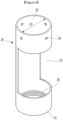
- FIG. 3 is a perspective view of a support portion according to an embodiment of the present disclosure
- FIG. 4 is a perspective view of a first support portion included in the support portion of FIG. 3
- FIG. 5 is a perspective view of a second support portion included in the support portion of FIG. 3 .
- a device for detecting a solution state may include a probe 10, a support portion 20, and a mesh 50.
- the probe 10 may be configured to detect the solution state (e.g., a concentration, a capacitance, or a inductance of a solution).
- the probe 10 may have a pillar shape, and have an upper portion fixed to or passing through an upper portion or a lid of a reactor, and a lower portion immersed in the solution in the reactor.
- a detecting portion 12 may be disposed in the lower portion of the probe 10, and detect the state of the solution which is present in or passes through the detecting portion 12.
- the lower portion of the probe 10, especially at least the detecting portion 12 may be disposed to be immersed in the solution.
- At least one surface of the detecting portion 12 may be open and function as an inlet through which the solution is introduced into the detecting portion 12 or an outlet through which the solution escapes from the detecting portion 12.
- the probe 10 has a circular column shape and the support portion 20 has a cylinder shape.
- the respective shapes of the probe 10 and the support portion 20 are not limited to the circular column shape and the cylinder shape.
- the probe 10 may be shown as having a diameter of D1.
- the support portion 20 may be provided to mount the mesh 50 around the detecting portion 12, and detachably mounted on the probe 10.
- the support portion 20 may have a hollow cylinder shape, and surround the probe 10.
- the support portion 20 may have an opening 22 formed therein.
- the opening 22 may surround a part of an outer peripheral surface of the probe 10, for example, at least the open surface of the detecting portion 12. Therefore, the solution in the reactor may be introduced into the detecting portion 12 only through the opening 22. That is, the opening 22 may form a path through which the solution is introduced into the detecting portion 12 of the probe 10.
- the support portion 20 may be provided as a single item, or may be provided as two or more items and may be detachably assembled to each other.
- the support portion 20 may include a first support portion 30 and a second support portion 40.
- the description exemplifies that the number of items included in the support portion 20 is two. However, it should be understood that the number of items included in the support portion 20 is not necessarily limited to two.
- the first support portion 30 may correspond to an outer shell of the support portion 20.
- the first support portion 30 may include a first opening 32 corresponding to the opening 22.
- the first support portion 30 includes a lower end 34 and an upper end 36.
- the lower end 34 of the first support portion 30 may be open so that the second support portion 40 may be inserted into the first support portion 30 from bottom to top.
- the upper end 36 of the first support portion 30 may be open so that the probe 10 may be inserted into the first support portion 30 from top to bottom, that is, so that the first support portion 30 may be moved from bottom to top to a mounting position of the first support portion 30 on the probe 10.
- the first support portion 30 may be shown as having an inner diameter of D2.
- the first support portion 30 may be detachably assembled to the second support portion 40.
- a first thread portion 39 may be formed on a lower portion of an inner peripheral surface of the first support portion 30, and may be screwed to the second support portion 40.
- the first support portion 30 may be detachably mounted on the outer peripheral surface of the probe 10.
- a fastening portion 38 may be formed in the upper portion of the first support portion 30.
- the fastening portion 38 may be a fastening hole. In this case, a corresponding fastening hole may be formed in the outer peripheral surface of the probe 10.
- the first support portion 30 may be mounted on the outer peripheral surface of the probe 10 by inserting a screw, a pin, or the like into the fastening hole of the first support portion 30 and the corresponding fastening hole of the probe 10.
- the first support portion 30 may be detached from the probe 10 by removing the screw, the pin, or the like from the fastening hole and/or the corresponding fastening hole.
- the description exemplifies that the fastening portion 38 is the fastening hole, and the present disclosure is not limited thereto.
- the second support portion 40 may correspond to an inner shell of the support portion 20.
- the second support portion 40 may include a second opening 42 corresponding to the opening 22. Therefore, when the first support portion 30 and the second support portion 40 are assembled to each other, the first opening 32 and the second opening 42 are coupled to each other to thus form the opening 22.
- the second support portion 40 may include a lower end 44 and an upper end 46.
- the lower end 44 of the second support portion 40 may be open, closed, or openable by a lid, or the like.
- the bubble occurring by an agitating device may have a low specific gravity to float on top of the solution. Therefore, the bubble may not be introduced to the detecting portion 12 through the open lower end 44 of the second support portion 40. Therefore, even when the lower end 44 of the second support portion 40 is open, the open lower end may have little effect on an operation of the detecting portion 12.
- the upper end 46 of the second support portion 40 may be open so that the probe 10 may be inserted into the second support portion 40 from top to bottom, that is, so that the second support portion 40 may be moved from bottom to top to a mounting position of the support portion 40 on the probe 10.
- the second support portion 40 may be shown as having an outer diameter of D3 and the second support portion 40 may be shown as having an inner diameter of D4.
- the second support portion 40 may be detachably assembled to the first support portion 30.
- a second thread portion 49 may be formed on a lower portion of an outer peripheral surface of the second support portion 40, and may be screwed to the first thread portion 39 of the first support portion 30.
- the upper end 46 of the second support portion 40 may be disposed below the fastening portion 38 so that the support portion 20 formed by coupling the first support portion 30 with the second support portion 40, may be detachably mounted on the outer peripheral surface of the probe 10. That is, the fastening portion 38 may be disposed above the upper end 46 of the second support portion 40. Therefore, the support portion 20 may be detachably mounted on the outer peripheral surface of the probe 10 by using only the fastening portion 38 without forming a fastening portion corresponding to the fastening portion 38 in the second support portion 40.
- the inner diameter D2 or the inner surface of the first support portion 30 may be spaced apart from the outer diameter D3 or the outer surface of the second support portion 40 by a predetermined distance.
- the predetermined distance may be provided to install the mesh 50 between the inner diameter D2 or the inner surface of the first support portion 30 and the outer diameter D3 or the outer surface of the second support portion 40.
- the predetermined distance is not limited thereto, and may range from 0.3 mm to 1 mm.
- the outer diameter D1 or the outer surface of the probe 10 and the inner diameter D4 or the inner surface of the second support portion 40 may be spaced apart from each other by the predetermined distance G1. Even if the bubble is present or introduced between the probe 10 and the support portion 20, the bubble may escape through the predetermined distance G1.
- the predetermined distance G1 is not limited thereto, and may range from 2 mm to 5 mm.
- the mesh 50 may be mounted in the opening 22 surrounding the open surface of the detecting portion 12 of the probe 10. That is, the mesh 50 may be disposed on the path through which the solution is introduced into the detecting portion 12 of the probe 10, thus preventing the bubble in the solution from being introduced into the detecting portion 12 of the probe 10. As described above, the mesh 50 may be mounted at the predetermined distance between the inner diameter D2 or the inner surface of the first support portion 30 and the outer diameter D3 or the outer surface of the second support portion 40. In addition, the lower end of the mesh 50 may not deviate from the predetermined distance by being supported by the first and second thread portions 39 and 49 screwed to each other.
- the mesh 50 may deviate only upward from the predetermined distance, which means that the mesh 50 does not deviate from the support portion 20 without a user's intention to detach the mesh 50.
- the mesh 50 is not limited to any particular size as long as the mesh has a large size enough to prevent the bubble from being introduced into the detecting portion 12.
- the mesh 50 could be a 300 mesh or a 500 mesh.
- the mesh 50 may have a size determined based on the size, flow rate, or the like of the bubble occurring in an operation condition of the reactor.
- the mesh 50 may be 100 mesh to 1000 mesh.
- a material of the mesh 50 is not particularly limited, and the mesh 50 may be used as long as the mesh 50 is made of a material that does not corrode in a liquid.
- the material of the mesh 50 may be a metal material such as a steel use stainless (SUS) material or a plastic material, which has a strong corrosion resistance.
- a hole in the mesh 50 is not limited to any particular shape as long as the mesh 50 may prevent passage of the bubble and reduce its flow rate.
- the hole may have various shapes, such as a circle or a polygon.
- the probe 10 may have the circular column shape, and may be configured to include the upper portion fixed to or passing through the upper portion or lid of the reactor and the lower portion immersed in the solution in the reactor.
- the support portion 20 may be formed by screwing the first and second thread portions 39 and 49 to each other and assembling the first and second support portions 30 and 40 to each other.
- the opening 22 may be formed by coupling the first and second openings 32 and 42 to each other.
- the upper end 46 of the second support portion 40 may be disposed below the fastening portion 38, and the inner diameter D2 of the first support portion 30 and the outer diameter D3 of the second support portion 40 may be spaced apart from each other by the predetermined distance.
- the mesh 50 may be inserted downward into the predetermined distance between the inner diameter D2 of the first support portion 30 and the outer diameter D3 of the second support portion 40.
- the mesh 50 may be mounted in the opening 22, which is the path through which the solution is introduced into the detecting portion 12 of the probe 10.
- the support portion 20 equipped with the mesh 50 may then be mounted on the outer peripheral surface of the probe 10 through the fastening portion 38.
- the mesh 50 may surround the open surface of the detecting portion 12, and the outer diameter D1 of the probe 10 and the inner diameter D4 of the second support portion 40 may be spaced apart from each other by the predetermined distance G1, thus forming a space for the bubble to escape between the probe 10 and the support portion 20.
- FIG. 6 shows a spectrum depending on the presence or absence of the bubble in the probe.
- FIG. 6 shows the spectrum for the cases where the bubble is present and absent in the detecting portion 12 of the probe 10 when the reactor is stopped.
- a dotted line represents the spectrum when the bubble is absent in the detecting portion 12
- a solid line represents the spectrum when bubble is present in the detecting portion 12.
- a peak having an intensity of 7000 ⁇ , 5000 ⁇ , or 4000 ⁇ may be generated.
- the bubble may cause the error in the detection value of the detecting portion 12, and the peak may not be generated or may have a low intensity even when the peak is generated.
- FIG. 7 shows an example of a spectrum of the culture fluid detected using the device for detecting a solution state according to an embodiment of the present disclosure
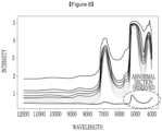
- FIG. 8 shows an example of a spectrum of a culture fluid detected using a device for detecting a solution state according to the prior art.
- FIGS. 7 and 8 show a change in the spectrum that is detected in a process of cultivating the colon bacillus for 24 hours.
- the spectrum indicated by the dotted line in FIG. 6 is generated when the spectrum of the culture fluid is detected using the device for detecting a solution state according to an embodiment of the present disclosure. That is, the device for detecting a solution state according to an embodiment of the present disclosure may prevent the bubble from being introduced to the detecting portion 12, thus acquiring an accurate spectrum.
- an abnormal section may be observed at a low wavelength when detecting the spectrum of the culture fluid using the device for detecting a solution state according to the prior art. That is, the device for detecting a solution state according to the prior art may not have a means to prevent the bubble from being introduced to the detecting portion, and an error may occur in the detection value.
Landscapes
- Chemical & Material Sciences (AREA)
- Health & Medical Sciences (AREA)
- Life Sciences & Earth Sciences (AREA)
- Engineering & Computer Science (AREA)
- Bioinformatics & Cheminformatics (AREA)
- Organic Chemistry (AREA)
- Zoology (AREA)
- Wood Science & Technology (AREA)
- Biotechnology (AREA)
- Biochemistry (AREA)
- General Health & Medical Sciences (AREA)
- Genetics & Genomics (AREA)
- General Engineering & Computer Science (AREA)
- Sustainable Development (AREA)
- Biomedical Technology (AREA)
- Microbiology (AREA)
- Analytical Chemistry (AREA)
- Medicinal Chemistry (AREA)
- Clinical Laboratory Science (AREA)
- Food Science & Technology (AREA)
- Pathology (AREA)
- Physics & Mathematics (AREA)
- General Physics & Mathematics (AREA)
- Immunology (AREA)
- Apparatus Associated With Microorganisms And Enzymes (AREA)
- Optical Measuring Cells (AREA)
- Measurement Of Radiation (AREA)
- Investigating Or Analyzing Materials By The Use Of Electric Means (AREA)
- Automatic Analysis And Handling Materials Therefor (AREA)
Abstract
Description
- This application claims priority to and the benefit of
Korean Patent Application No. 10-2022-0102208 filed in the Korean Intellectual Property Office on August 16, 2022 - The present disclosure relates to a device for detecting a solution state, and more particularly, to a device for detecting a solution state which may include a mesh disposed in a path through which a solution is introduced into a probe for detecting the solution state to prevent a bubble from entering a detecting portion of the probe, thereby preventing an error from occurring in the detected solution state.
- 3-Hydropropionic Acid (3-HP) may be a platform compound that may be converted into many other useful chemicals, including acrylic acid, and thus may be widely applied to production of pigments, paints, fibers, or the like. The 3-HP may be a representative biodegradable material that may be produced by fermenting colon bacillus.
- The colon bacillus may be cultured and fermented in a culture fluid in a reactor. A spectrometer may be installed in this reactor to detect a concentration of the colon bacillus in the culture fluid in real time. In addition, various detection devices may be installed in the reactor to detect a state (e.g., concentration, capacitance, or inductance) of the culture fluid, thereby predicting a state of the colon bacillus. These detection devices may be typically configured to detect the state of the culture fluid flowing into the detecting portion in real time.
- An agitating device may also be disposed in the reactor for cultivating the colon bacillus. The agitating device may be configured to agitate the culture fluid and supply oxygen to the colon bacillus in the culture fluid. When the agitating device is operated and agitates the culture fluid, a bubble or the like may occur in the culture fluid, and the occurring bubble may be introduced into the detecting portion of the detection device along with the culture fluid. As such, when the bubble is present in or passes through the detecting portion, the state of the culture fluid detected by the detection device may not be uniform. That is, an error may occur in the state of the culture fluid detected by the detection device.
- The above information disclosed in this Background section is provided only to assist in more understanding of the background of the present disclosure, and may thus include information not included in the prior art already known to those skilled in the art to which the present disclosure pertains.
- The present disclosure attempts to provide a device for detecting a solution state which may include a mesh disposed in a path through which a solution is introduced into a probe for detecting the solution state to prevent a bubble from entering the probe.
- According to an embodiment, privided is a device for detecting a solution state, the device including: a probe including a detecting portion having at least one open surface to detect the solution state; a mesh disposed on a path through which a solution is introduced into the detecting portion; and a support portion disposed on an outside of the probe, and having an opening surrounding the at least one open surface of the detecting portion, wherein the opening defines the path through which the solution is introduced into the detecting portion, and the mesh is mounted in the opening of the support portion.
- An inner surface of the support portion may be spaced apart from an outer surface of the probe by a predetermined distance.
- The support portion may be detachably mounted on an outer surface of the probe through a fastening portion.
- The support portion may include first and second support portions spaced apart from each other by a predetermined distance, and the first and second support portions may be detachably assembled to each other for the mesh to be mounted at the predetermined distance between the first and second support portions.
- The first and second support portions may be screwed to each other.
- The second support portion may be inserted into the first support portion while being spaced apart from the first support portion by the predetermined distance, and a first thread portion may be formed on an inner surface of a lower portion of the first support portion, a second thread portion may be formed on an outer surface of a lower portion of the second support portion, and the first thread portion and the second thread portion may be screwed to each other.
- Upper ends of the first and second support portions may be open.
- A lower end of the first support portion may be open, and a lower end of the second support portion may be open, closed, or openable.
- An inner surface of the second support portion and an outer surface of the probe may be spaced apart from each other by the predetermined distance.
- A fastening portion may be formed in an upper portion of the first support portion, and the support portion may be detachably mounted on an outer surface of the probe through the fastening portion.
- The fastening portion may be disposed above an upper end of the second support portion.
- According to the present disclosure, the mesh may be disposed in the path through which the solution is introduced into the probe to prevent the bubble from entering the probe.
- In addition, the mesh may be mounted on the support portion, and the support portion may be detachably mounted on the probe. Accordingly, the mesh and the support portion may thus be easily installed or replaced.
- In addition, the support portion may be made larger than the probe by the predetermined size, thereby preventing the bubble from escaping out of the support portion and causing the error in the detection value of the state even if the bubble is present between the support portion and the probe.
- Other effects which may be acquired or predicted by the embodiments of the present disclosure are disclosed directly or implicitly in the detailed description of the embodiments of the present disclosure. That is, various effects predicted based on the embodiments of the present disclosure are disclosed in the detailed description described below.
- Embodiments in the specification may be better understood by reference to the following description in connection with the accompanying drawings in which like reference numerals refer to identical or functionally similar elements.
-
FIG. 1 is a perspective view of a device for detecting a solution state according to an embodiment of the present disclosure. -
FIG. 2 is a perspective view of a probe according to an embodiment of the present disclosure. -
FIG. 3 is a perspective view of a support portion according to an embodiment of the present disclosure. -
FIG. 4 is a perspective view of a first support portion included in the support portion ofFIG. 3 . -
FIG. 5 is a perspective view of a second support portion included in the support portion ofFIG. 3 . -
FIG. 6 shows a spectrum depending on the presence or absence of a bubble in the probe. -
FIG. 7 shows an example of a spectrum of a culture fluid detected using a device for detecting a solution state according to an embodiment of the present disclosure. -
FIG. 8 shows an example of a spectrum of a culture fluid detected using a device for detecting a solution state according to the prior art. - It should be understood that the drawings referenced above are not necessarily drawn to scale, and present a rather simplified representation of various preferred features showing the basic principles of the present disclosure. For example, specific design features of the present disclosure, including its specific dimension, orientation, position and shape, are determined in part by the particular intended application and environment of use.
- A term used herein is only to describe a specific embodiment, and is not intended to limit the present disclosure. A term of a singular number used herein is intended to include its plural number unless the context clearly indicates otherwise. It should also be understood that the terms "include" and/or "including," when used in the specification, specify the presence of the recited features, integers, steps, operations, elements and/or components, and do not exclude the presence or addition of one or more of other features, integers, steps, operations, elements, components and/or groups thereof. A term "and/or" used herein includes any one or all combinations of the associated listed items.
- A device for detecting a solution state according to an embodiment of the present disclosure may include a mesh disposed in a path through which a solution is introduced into a probe to prevent a bubble from entering the probe. Accordingly, it is possible to accurately detect the solution state. In addition, the mesh may be mounted on a support portion, and the support portion may be detachably mounted on the probe. Accordingly, the mesh and the support portion may thus be easily installed or replaced. In addition, the support portion may be made larger than the probe by a predetermined size, thereby preventing the bubble from escaping out of the support portion and causing an error in a detection value of the state even if the bubble is present between the support portion and the probe.
- Hereinafter, an embodiment of the present disclosure is described in detail with reference to the accompanying drawings.
-
FIG. 1 is a perspective view of a device for detecting a solution state according to an embodiment of the present disclosure;FIG. 2 is a perspective view of a probe according to an embodiment of the present disclosure;FIG. 3 is a perspective view of a support portion according to an embodiment of the present disclosure;FIG. 4 is a perspective view of a first support portion included in the support portion ofFIG. 3 ; andFIG. 5 is a perspective view of a second support portion included in the support portion ofFIG. 3 . - As shown in
FIGS. 1 to 5 , a device for detecting a solution state according to an embodiment of the present disclosure may include aprobe 10, asupport portion 20, and amesh 50. - As shown in
FIGS. 1 and2 , theprobe 10 may be configured to detect the solution state (e.g., a concentration, a capacitance, or a inductance of a solution). Theprobe 10 may have a pillar shape, and have an upper portion fixed to or passing through an upper portion or a lid of a reactor, and a lower portion immersed in the solution in the reactor. For example, a detectingportion 12 may be disposed in the lower portion of theprobe 10, and detect the state of the solution which is present in or passes through the detectingportion 12. For this purpose, the lower portion of theprobe 10, especially at least the detectingportion 12, may be disposed to be immersed in the solution. In addition, at least one surface of the detectingportion 12 may be open and function as an inlet through which the solution is introduced into the detectingportion 12 or an outlet through which the solution escapes from the detectingportion 12. In this specification, it is exemplified that theprobe 10 has a circular column shape and thesupport portion 20 has a cylinder shape. However, the respective shapes of theprobe 10 and thesupport portion 20 are not limited to the circular column shape and the cylinder shape. When theprobe 10 has the circular column shape, theprobe 10 may be shown as having a diameter of D1. - As shown in
FIGS. 1 and3 , thesupport portion 20 may be provided to mount themesh 50 around the detectingportion 12, and detachably mounted on theprobe 10. When theprobe 10 has the circular column shape, thesupport portion 20 may have a hollow cylinder shape, and surround theprobe 10. Thesupport portion 20 may have anopening 22 formed therein. Theopening 22 may surround a part of an outer peripheral surface of theprobe 10, for example, at least the open surface of the detectingportion 12. Therefore, the solution in the reactor may be introduced into the detectingportion 12 only through theopening 22. That is, theopening 22 may form a path through which the solution is introduced into the detectingportion 12 of theprobe 10. - The
support portion 20 may be provided as a single item, or may be provided as two or more items and may be detachably assembled to each other. In an example, thesupport portion 20 may include afirst support portion 30 and asecond support portion 40. Here, the description exemplifies that the number of items included in thesupport portion 20 is two. However, it should be understood that the number of items included in thesupport portion 20 is not necessarily limited to two. - As shown in
FIGS. 1 ,3 and4 , thefirst support portion 30 may correspond to an outer shell of thesupport portion 20. Thefirst support portion 30 may include afirst opening 32 corresponding to theopening 22. In addition, thefirst support portion 30 includes alower end 34 and anupper end 36. Thelower end 34 of thefirst support portion 30 may be open so that thesecond support portion 40 may be inserted into thefirst support portion 30 from bottom to top. Similarly, theupper end 36 of thefirst support portion 30 may be open so that theprobe 10 may be inserted into thefirst support portion 30 from top to bottom, that is, so that thefirst support portion 30 may be moved from bottom to top to a mounting position of thefirst support portion 30 on theprobe 10. When thefirst support portion 30 has the hollow cylinder shape, thefirst support portion 30 may be shown as having an inner diameter of D2. - The
first support portion 30 may be detachably assembled to thesecond support portion 40. In an example, afirst thread portion 39 may be formed on a lower portion of an inner peripheral surface of thefirst support portion 30, and may be screwed to thesecond support portion 40. In addition, thefirst support portion 30 may be detachably mounted on the outer peripheral surface of theprobe 10. For this purpose, afastening portion 38 may be formed in the upper portion of thefirst support portion 30. In an example, thefastening portion 38 may be a fastening hole. In this case, a corresponding fastening hole may be formed in the outer peripheral surface of theprobe 10. Accordingly, thefirst support portion 30 may be mounted on the outer peripheral surface of theprobe 10 by inserting a screw, a pin, or the like into the fastening hole of thefirst support portion 30 and the corresponding fastening hole of theprobe 10. In addition, thefirst support portion 30 may be detached from theprobe 10 by removing the screw, the pin, or the like from the fastening hole and/or the corresponding fastening hole. Here, the description exemplifies that thefastening portion 38 is the fastening hole, and the present disclosure is not limited thereto. - As shown in
FIGS. 1 ,3 and5 , thesecond support portion 40 may correspond to an inner shell of thesupport portion 20. Thesecond support portion 40 may include asecond opening 42 corresponding to theopening 22. Therefore, when thefirst support portion 30 and thesecond support portion 40 are assembled to each other, thefirst opening 32 and thesecond opening 42 are coupled to each other to thus form theopening 22. - The
second support portion 40 may include alower end 44 and anupper end 46. Thelower end 44 of thesecond support portion 40 may be open, closed, or openable by a lid, or the like. In general, the bubble occurring by an agitating device may have a low specific gravity to float on top of the solution. Therefore, the bubble may not be introduced to the detectingportion 12 through the openlower end 44 of thesecond support portion 40. Therefore, even when thelower end 44 of thesecond support portion 40 is open, the open lower end may have little effect on an operation of the detectingportion 12. Theupper end 46 of thesecond support portion 40 may be open so that theprobe 10 may be inserted into thesecond support portion 40 from top to bottom, that is, so that thesecond support portion 40 may be moved from bottom to top to a mounting position of thesupport portion 40 on theprobe 10. When thesecond support portion 40 has the hollow cylinder shape, thesecond support portion 40 may be shown as having an outer diameter of D3 and thesecond support portion 40 may be shown as having an inner diameter of D4. - As described above, the
second support portion 40 may be detachably assembled to thefirst support portion 30. In an example, asecond thread portion 49 may be formed on a lower portion of an outer peripheral surface of thesecond support portion 40, and may be screwed to thefirst thread portion 39 of thefirst support portion 30. In addition, theupper end 46 of thesecond support portion 40 may be disposed below thefastening portion 38 so that thesupport portion 20 formed by coupling thefirst support portion 30 with thesecond support portion 40, may be detachably mounted on the outer peripheral surface of theprobe 10. That is, thefastening portion 38 may be disposed above theupper end 46 of thesecond support portion 40. Therefore, thesupport portion 20 may be detachably mounted on the outer peripheral surface of theprobe 10 by using only thefastening portion 38 without forming a fastening portion corresponding to thefastening portion 38 in thesecond support portion 40. - In an example, the inner diameter D2 or the inner surface of the
first support portion 30 may be spaced apart from the outer diameter D3 or the outer surface of thesecond support portion 40 by a predetermined distance. The predetermined distance may be provided to install themesh 50 between the inner diameter D2 or the inner surface of thefirst support portion 30 and the outer diameter D3 or the outer surface of thesecond support portion 40. The predetermined distance is not limited thereto, and may range from 0.3 mm to 1 mm. In addition, the outer diameter D1 or the outer surface of theprobe 10 and the inner diameter D4 or the inner surface of thesecond support portion 40 may be spaced apart from each other by the predetermined distance G1. Even if the bubble is present or introduced between theprobe 10 and thesupport portion 20, the bubble may escape through the predetermined distance G1. The predetermined distance G1 is not limited thereto, and may range from 2 mm to 5 mm. - The
mesh 50 may be mounted in theopening 22 surrounding the open surface of the detectingportion 12 of theprobe 10. That is, themesh 50 may be disposed on the path through which the solution is introduced into the detectingportion 12 of theprobe 10, thus preventing the bubble in the solution from being introduced into the detectingportion 12 of theprobe 10. As described above, themesh 50 may be mounted at the predetermined distance between the inner diameter D2 or the inner surface of thefirst support portion 30 and the outer diameter D3 or the outer surface of thesecond support portion 40. In addition, the lower end of themesh 50 may not deviate from the predetermined distance by being supported by the first andsecond thread portions mesh 50 may deviate only upward from the predetermined distance, which means that themesh 50 does not deviate from thesupport portion 20 without a user's intention to detach themesh 50. Themesh 50 is not limited to any particular size as long as the mesh has a large size enough to prevent the bubble from being introduced into the detectingportion 12. In an example, themesh 50 could be a 300 mesh or a 500 mesh. In another example, themesh 50 may have a size determined based on the size, flow rate, or the like of the bubble occurring in an operation condition of the reactor. For example, themesh 50 may be 100 mesh to 1000 mesh. - A material of the
mesh 50 is not particularly limited, and themesh 50 may be used as long as themesh 50 is made of a material that does not corrode in a liquid. In an example, the material of themesh 50 may be a metal material such as a steel use stainless (SUS) material or a plastic material, which has a strong corrosion resistance. - In addition, a hole in the
mesh 50 is not limited to any particular shape as long as themesh 50 may prevent passage of the bubble and reduce its flow rate. In an example, the hole may have various shapes, such as a circle or a polygon. - Hereinafter, the description briefly describes a process of installing the device for detecting a solution state on the
probe 10. In an example, theprobe 10 may have the circular column shape, and may be configured to include the upper portion fixed to or passing through the upper portion or lid of the reactor and the lower portion immersed in the solution in the reactor. - First, the
support portion 20 may be formed by screwing the first andsecond thread portions second support portions opening 22 may be formed by coupling the first andsecond openings upper end 46 of thesecond support portion 40 may be disposed below thefastening portion 38, and the inner diameter D2 of thefirst support portion 30 and the outer diameter D3 of thesecond support portion 40 may be spaced apart from each other by the predetermined distance. - In this state, the
mesh 50 may be inserted downward into the predetermined distance between the inner diameter D2 of thefirst support portion 30 and the outer diameter D3 of thesecond support portion 40. Themesh 50 may be mounted in theopening 22, which is the path through which the solution is introduced into the detectingportion 12 of theprobe 10. - The
support portion 20 equipped with themesh 50 may then be mounted on the outer peripheral surface of theprobe 10 through thefastening portion 38. Here, themesh 50 may surround the open surface of the detectingportion 12, and the outer diameter D1 of theprobe 10 and the inner diameter D4 of thesecond support portion 40 may be spaced apart from each other by the predetermined distance G1, thus forming a space for the bubble to escape between theprobe 10 and thesupport portion 20. - Hereinafter, the description describes an effect of the device for detecting a solution state according to an embodiment of the present disclosure.
-
FIG. 6 shows a spectrum depending on the presence or absence of the bubble in the probe.FIG. 6 shows the spectrum for the cases where the bubble is present and absent in the detectingportion 12 of theprobe 10 when the reactor is stopped. InFIG. 6 , a dotted line represents the spectrum when the bubble is absent in the detectingportion 12, and a solid line represents the spectrum when bubble is present in the detectingportion 12. - As may be seen from the dotted line in
FIG. 6 , when the bubble is absent in the detectingportion 12, a peak having an intensity of 7000 Å, 5000 Å, or 4000 Å may be generated. However, as may be seen from the solid line inFIG. 6 , when the bubble is present in the detectingportion 12, the bubble may cause the error in the detection value of the detectingportion 12, and the peak may not be generated or may have a low intensity even when the peak is generated. -
FIG. 7 shows an example of a spectrum of the culture fluid detected using the device for detecting a solution state according to an embodiment of the present disclosure; andFIG. 8 shows an example of a spectrum of a culture fluid detected using a device for detecting a solution state according to the prior art.FIGS. 7 and8 show a change in the spectrum that is detected in a process of cultivating the colon bacillus for 24 hours. - As shown in
FIG. 7 , it may be seen that the spectrum indicated by the dotted line inFIG. 6 is generated when the spectrum of the culture fluid is detected using the device for detecting a solution state according to an embodiment of the present disclosure. That is, the device for detecting a solution state according to an embodiment of the present disclosure may prevent the bubble from being introduced to the detectingportion 12, thus acquiring an accurate spectrum. - As shown in
FIG. 8 , an abnormal section may be observed at a low wavelength when detecting the spectrum of the culture fluid using the device for detecting a solution state according to the prior art. That is, the device for detecting a solution state according to the prior art may not have a means to prevent the bubble from being introduced to the detecting portion, and an error may occur in the detection value. - Although the embodiments of the present disclosure have been described hereinabove, the scope of the present disclosure is not limited thereto, and all equivalent modifications easily modified by those skilled in the art to which the present disclosure pertains are intended to fall within the scope and spirit of the present disclosure.
Claims (11)
- A device for detecting a solution state, the device comprising:a probe including a detecting portion having at least one open surface to detect the solution state;a mesh disposed on a path through which a solution is introduced into the detecting portion; anda support portion disposed on an outside of the probe, and having an opening surrounding the at least one open surface of the detecting portion,wherein the opening defines the path through which the solution is introduced into the detecting portion, andthe mesh is mounted in the opening of the support portion.
- The device of claim 1, wherein
an inner surface of the support portion is spaced apart from an outer surface of the probe by a predetermined distance. - The device of claim 1, wherein
the support portion is detachably mounted on an outer surface of the probe through a fastening portion. - The device of claim 1, whereinthe support portion includes first and second support portions spaced apart from each other by a predetermined distance, andthe first and second support portions are detachably assembled to each other for the mesh to be mounted at the predetermined distance between the first and second support portions.
- The device of claim 4, wherein
the first and second support portions are screwed to each other. - The device of claim 5, whereinthe second support portion is inserted into the first support portion while being spaced apart from the first support portion by the predetermined distance, anda first thread portion is formed on an inner surface of a lower portion of the first support portion, a second thread portion is formed on an outer surface of a lower portion of the second support portion, and the first thread portion and the second thread portion are screwed to each other.
- The device of claim 4, wherein
upper ends of the first and second support portions are open. - The device of claim 4, whereina lower end of the first support portion is open, anda lower end of the second support portion is open, closed, or openable.
- The device of claim 4, wherein
an inner surface of the second support portion and an outer surface of the probe are spaced apart from each other by the predetermined distance. - The device of claim 4, whereina fastening portion is formed in an upper portion of the first support portion, andthe support portion is detachably mounted on an outer surface of the probe through the fastening portion.
- The device of claim 10, wherein
the fastening portion is disposed above an upper end of the second support portion.
Applications Claiming Priority (3)
| Application Number | Priority Date | Filing Date | Title |
|---|---|---|---|
| KR20220102208 | 2022-08-16 | ||
| KR1020230085322A KR20240024009A (en) | 2022-08-16 | 2023-06-30 | Device of detecting state of solution |
| PCT/KR2023/009556 WO2024039068A1 (en) | 2022-08-16 | 2023-07-06 | Solution state measurement device |
Publications (2)
| Publication Number | Publication Date |
|---|---|
| EP4428221A1 true EP4428221A1 (en) | 2024-09-11 |
| EP4428221A4 EP4428221A4 (en) | 2025-04-09 |
Family
ID=89942087
Family Applications (1)
| Application Number | Title | Priority Date | Filing Date |
|---|---|---|---|
| EP23855039.6A Pending EP4428221A4 (en) | 2022-08-16 | 2023-07-06 | Solution state measurement device |
Country Status (4)
| Country | Link |
|---|---|
| US (1) | US20250043229A1 (en) |
| EP (1) | EP4428221A4 (en) |
| JP (1) | JP7733241B2 (en) |
| WO (1) | WO2024039068A1 (en) |
Family Cites Families (10)
| Publication number | Priority date | Publication date | Assignee | Title |
|---|---|---|---|---|
| JPS5850306Y2 (en) * | 1978-05-25 | 1983-11-16 | 株式会社明電舎 | Water quality measuring device |
| JPH053971Y2 (en) * | 1986-05-27 | 1993-01-29 | ||
| JP2006317285A (en) * | 2005-05-12 | 2006-11-24 | Matsushita Electric Ind Co Ltd | Biosensor |
| JP5041721B2 (en) * | 2006-03-29 | 2012-10-03 | 中国電力株式会社 | Plankton distribution research ship |
| EP2449368A2 (en) * | 2009-06-30 | 2012-05-09 | Advanced Technology Materials, Inc. | Fluid monitoring apparatus |
| KR20110040356A (en) * | 2009-10-14 | 2011-04-20 | (주)이지정보기술 | Sensor socket with protection filter for pollution prevention |
| GB2479783A (en) * | 2010-04-23 | 2011-10-26 | Aber Instr Ltd | A bioreactor with an impedance or biomass measuring probe. |
| KR101489630B1 (en) * | 2013-05-27 | 2015-02-06 | 주식회사 과학기술분석센타 | water sensor probe of which sensor is cleaned for itself |
| KR101887472B1 (en) * | 2018-05-08 | 2018-09-10 | 대한민국 | Anti-fouling sensor unit using a principle of sea-water electric cell |
| WO2020009022A1 (en) * | 2018-07-06 | 2020-01-09 | 味の素株式会社 | Sensor cover, sensor device provided with same, liquid property measuring method and method for producing metabolite in aeration culture |
-
2023
- 2023-07-06 WO PCT/KR2023/009556 patent/WO2024039068A1/en not_active Ceased
- 2023-07-06 EP EP23855039.6A patent/EP4428221A4/en active Pending
- 2023-07-06 US US18/718,150 patent/US20250043229A1/en active Pending
- 2023-07-06 JP JP2024529264A patent/JP7733241B2/en active Active
Also Published As
| Publication number | Publication date |
|---|---|
| US20250043229A1 (en) | 2025-02-06 |
| JP2024541399A (en) | 2024-11-08 |
| JP7733241B2 (en) | 2025-09-02 |
| WO2024039068A1 (en) | 2024-02-22 |
| EP4428221A4 (en) | 2025-04-09 |
Similar Documents
| Publication | Publication Date | Title |
|---|---|---|
| US4330385A (en) | Dissolved oxygen measurement instrument | |
| US9228863B2 (en) | Retractable assembly | |
| KR101754738B1 (en) | Corrosion apparatus for sample | |
| US20110163028A1 (en) | Biofilm Reactor Containing Spiral Structure and Water Treatment Device Using the Same | |
| US20250043229A1 (en) | Device for Detecting Solution State | |
| JP2023184548A (en) | Sensor cover, sensor device equipped with the same, method for measuring liquid properties, and method for producing metabolic products in aerated culture | |
| CN118251486A (en) | Solution state detection device | |
| KR20240024009A (en) | Device of detecting state of solution | |
| KR100754853B1 (en) | Appropriate metering and reaction device for water quality analysis system | |
| WO2021062222A1 (en) | Chemistry vessel agitator | |
| CN207623217U (en) | A kind of water quality automatic checkout equipment | |
| CN211905339U (en) | Water toxicity detection device | |
| US12078609B2 (en) | System and method for measuring a variable of a liquid | |
| JP3191725U (en) | Tubular parts | |
| CN220496378U (en) | Multi-connected mixed reaction device | |
| KR102936362B1 (en) | Agitator | |
| CN223016841U (en) | Fermentation tank body device based on dissolved oxygen concentration detection | |
| JP6339804B2 (en) | Incubator | |
| US20240110886A1 (en) | Amperometric sensor with bubble shedding clip | |
| EP4553481A1 (en) | Device for measuring state of solution | |
| US20250198889A1 (en) | Inductive Stirring System for Chemical Analysis System | |
| US20080145921A1 (en) | Tissue Bath System With Air Heating | |
| WO2015028833A2 (en) | Sample holder vessel, especially for automated sampling | |
| CN223910849U (en) | PH on-line detection device for reaction kettle and reaction kettle | |
| CN217262182U (en) | Pushing, hand hole or manhole structure |
Legal Events
| Date | Code | Title | Description |
|---|---|---|---|
| STAA | Information on the status of an ep patent application or granted ep patent |
Free format text: STATUS: THE INTERNATIONAL PUBLICATION HAS BEEN MADE |
|
| PUAI | Public reference made under article 153(3) epc to a published international application that has entered the european phase |
Free format text: ORIGINAL CODE: 0009012 |
|
| STAA | Information on the status of an ep patent application or granted ep patent |
Free format text: STATUS: REQUEST FOR EXAMINATION WAS MADE |
|
| 17P | Request for examination filed |
Effective date: 20240605 |
|
| AK | Designated contracting states |
Kind code of ref document: A1 Designated state(s): AL AT BE BG CH CY CZ DE DK EE ES FI FR GB GR HR HU IE IS IT LI LT LU LV MC ME MK MT NL NO PL PT RO RS SE SI SK SM TR |
|
| A4 | Supplementary search report drawn up and despatched |
Effective date: 20250310 |
|
| RIC1 | Information provided on ipc code assigned before grant |
Ipc: G01N 33/18 20060101ALI20250304BHEP Ipc: C12M 1/21 20060101ALI20250304BHEP Ipc: C12M 1/34 20060101AFI20250304BHEP |
|
| DAV | Request for validation of the european patent (deleted) | ||
| DAX | Request for extension of the european patent (deleted) |