EP4428091A2 - High temperature piezo-resistive pressure sensor and packaging assembly therefor - Google Patents
High temperature piezo-resistive pressure sensor and packaging assembly therefor Download PDFInfo
- Publication number
- EP4428091A2 EP4428091A2 EP24161954.3A EP24161954A EP4428091A2 EP 4428091 A2 EP4428091 A2 EP 4428091A2 EP 24161954 A EP24161954 A EP 24161954A EP 4428091 A2 EP4428091 A2 EP 4428091A2
- Authority
- EP
- European Patent Office
- Prior art keywords
- pressure sensor
- glass frit
- pressure
- diaphragm
- housing
- Prior art date
- Legal status (The legal status is an assumption and is not a legal conclusion. Google has not performed a legal analysis and makes no representation as to the accuracy of the status listed.)
- Pending
Links
Images




Classifications
-
- G—PHYSICS
- G01—MEASURING; TESTING
- G01L—MEASURING FORCE, STRESS, TORQUE, WORK, MECHANICAL POWER, MECHANICAL EFFICIENCY, OR FLUID PRESSURE
- G01L9/00—Measuring steady of quasi-steady pressure of fluid or fluent solid material by electric or magnetic pressure-sensitive elements; Transmitting or indicating the displacement of mechanical pressure-sensitive elements, used to measure the steady or quasi-steady pressure of a fluid or fluent solid material, by electric or magnetic means
- G01L9/0041—Transmitting or indicating the displacement of flexible diaphragms
- G01L9/0042—Constructional details associated with semiconductive diaphragm sensors, e.g. etching, or constructional details of non-semiconductive diaphragms
- G01L9/0047—Diaphragm with non uniform thickness, e.g. with grooves, bosses or continuously varying thickness
-
- G—PHYSICS
- G01—MEASURING; TESTING
- G01L—MEASURING FORCE, STRESS, TORQUE, WORK, MECHANICAL POWER, MECHANICAL EFFICIENCY, OR FLUID PRESSURE
- G01L9/00—Measuring steady of quasi-steady pressure of fluid or fluent solid material by electric or magnetic pressure-sensitive elements; Transmitting or indicating the displacement of mechanical pressure-sensitive elements, used to measure the steady or quasi-steady pressure of a fluid or fluent solid material, by electric or magnetic means
- G01L9/0041—Transmitting or indicating the displacement of flexible diaphragms
- G01L9/0051—Transmitting or indicating the displacement of flexible diaphragms using variations in ohmic resistance
- G01L9/0052—Transmitting or indicating the displacement of flexible diaphragms using variations in ohmic resistance of piezoresistive elements
-
- B—PERFORMING OPERATIONS; TRANSPORTING
- B81—MICROSTRUCTURAL TECHNOLOGY
- B81B—MICROSTRUCTURAL DEVICES OR SYSTEMS, e.g. MICROMECHANICAL DEVICES
- B81B7/00—Microstructural systems ; Auxiliary parts of microstructural devices or systems
- B81B7/0032—Packages or encapsulation
- B81B7/0035—Packages or encapsulation for maintaining a controlled atmosphere inside of the chamber containing the MEMS
- B81B7/0041—Packages or encapsulation for maintaining a controlled atmosphere inside of the chamber containing the MEMS maintaining a controlled atmosphere with techniques not provided for in B81B7/0038
-
- G—PHYSICS
- G01—MEASURING; TESTING
- G01L—MEASURING FORCE, STRESS, TORQUE, WORK, MECHANICAL POWER, MECHANICAL EFFICIENCY, OR FLUID PRESSURE
- G01L19/00—Details of, or accessories for, apparatus for measuring steady or quasi-steady pressure of a fluent medium insofar as such details or accessories are not special to particular types of pressure gauges
- G01L19/0061—Electrical connection means
- G01L19/0069—Electrical connection means from the sensor to its support
-
- G—PHYSICS
- G01—MEASURING; TESTING
- G01L—MEASURING FORCE, STRESS, TORQUE, WORK, MECHANICAL POWER, MECHANICAL EFFICIENCY, OR FLUID PRESSURE
- G01L19/00—Details of, or accessories for, apparatus for measuring steady or quasi-steady pressure of a fluent medium insofar as such details or accessories are not special to particular types of pressure gauges
- G01L19/0061—Electrical connection means
- G01L19/0084—Electrical connection means to the outside of the housing
-
- G—PHYSICS
- G01—MEASURING; TESTING
- G01L—MEASURING FORCE, STRESS, TORQUE, WORK, MECHANICAL POWER, MECHANICAL EFFICIENCY, OR FLUID PRESSURE
- G01L19/00—Details of, or accessories for, apparatus for measuring steady or quasi-steady pressure of a fluent medium insofar as such details or accessories are not special to particular types of pressure gauges
- G01L19/14—Housings
- G01L19/147—Details about the mounting of the sensor to support or covering means
-
- G—PHYSICS
- G01—MEASURING; TESTING
- G01L—MEASURING FORCE, STRESS, TORQUE, WORK, MECHANICAL POWER, MECHANICAL EFFICIENCY, OR FLUID PRESSURE
- G01L9/00—Measuring steady of quasi-steady pressure of fluid or fluent solid material by electric or magnetic pressure-sensitive elements; Transmitting or indicating the displacement of mechanical pressure-sensitive elements, used to measure the steady or quasi-steady pressure of a fluid or fluent solid material, by electric or magnetic means
- G01L9/0041—Transmitting or indicating the displacement of flexible diaphragms
- G01L9/0042—Constructional details associated with semiconductive diaphragm sensors, e.g. etching, or constructional details of non-semiconductive diaphragms
-
- G—PHYSICS
- G01—MEASURING; TESTING
- G01L—MEASURING FORCE, STRESS, TORQUE, WORK, MECHANICAL POWER, MECHANICAL EFFICIENCY, OR FLUID PRESSURE
- G01L9/00—Measuring steady of quasi-steady pressure of fluid or fluent solid material by electric or magnetic pressure-sensitive elements; Transmitting or indicating the displacement of mechanical pressure-sensitive elements, used to measure the steady or quasi-steady pressure of a fluid or fluent solid material, by electric or magnetic means
- G01L9/0041—Transmitting or indicating the displacement of flexible diaphragms
- G01L9/0042—Constructional details associated with semiconductive diaphragm sensors, e.g. etching, or constructional details of non-semiconductive diaphragms
- G01L9/0048—Details about the mounting of the diaphragm to its support or about the diaphragm edges, e.g. notches, round shapes for stress relief
-
- G—PHYSICS
- G01—MEASURING; TESTING
- G01L—MEASURING FORCE, STRESS, TORQUE, WORK, MECHANICAL POWER, MECHANICAL EFFICIENCY, OR FLUID PRESSURE
- G01L9/00—Measuring steady of quasi-steady pressure of fluid or fluent solid material by electric or magnetic pressure-sensitive elements; Transmitting or indicating the displacement of mechanical pressure-sensitive elements, used to measure the steady or quasi-steady pressure of a fluid or fluent solid material, by electric or magnetic means
- G01L9/0041—Transmitting or indicating the displacement of flexible diaphragms
- G01L9/0051—Transmitting or indicating the displacement of flexible diaphragms using variations in ohmic resistance
- G01L9/0052—Transmitting or indicating the displacement of flexible diaphragms using variations in ohmic resistance of piezoresistive elements
- G01L9/0055—Transmitting or indicating the displacement of flexible diaphragms using variations in ohmic resistance of piezoresistive elements bonded on a diaphragm
-
- B—PERFORMING OPERATIONS; TRANSPORTING
- B81—MICROSTRUCTURAL TECHNOLOGY
- B81B—MICROSTRUCTURAL DEVICES OR SYSTEMS, e.g. MICROMECHANICAL DEVICES
- B81B2201/00—Specific applications of microelectromechanical systems
- B81B2201/02—Sensors
- B81B2201/0264—Pressure sensors
-
- B—PERFORMING OPERATIONS; TRANSPORTING
- B81—MICROSTRUCTURAL TECHNOLOGY
- B81B—MICROSTRUCTURAL DEVICES OR SYSTEMS, e.g. MICROMECHANICAL DEVICES
- B81B2203/00—Basic microelectromechanical structures
- B81B2203/01—Suspended structures, i.e. structures allowing a movement
- B81B2203/0127—Diaphragms, i.e. structures separating two media that can control the passage from one medium to another; Membranes, i.e. diaphragms with filtering function
-
- B—PERFORMING OPERATIONS; TRANSPORTING
- B81—MICROSTRUCTURAL TECHNOLOGY
- B81B—MICROSTRUCTURAL DEVICES OR SYSTEMS, e.g. MICROMECHANICAL DEVICES
- B81B2203/00—Basic microelectromechanical structures
- B81B2203/03—Static structures
- B81B2203/0315—Cavities
Definitions
- the subject disclosure is directed to pressure sensors, and more particularly, to a high temperature piezo-resistive pressure sensor and a packaging assembly for a high temperature piezo-resistive pressure sensor.
- MEMS pressure sensors have a wide range of useful applications in many commercial and industrial systems including aerospace, automotive, oil and gas drilling and consumer electronics. In most applications, MEMS pressure sensors convert a pressure signal to an electrical signal through a piezo-resistive effect. This sensing principle has significant advantages when employed in high temperature environments in terms of stability, signal processing convenience and accuracy.
- the sensor packaging assembly In a high temperature environment, not only does the pressure sensor and its individual components have to survive and function correctly, the sensor packaging assembly must also be designed to withstand high operating temperatures. It would be beneficial to provide a piezo-resistive pressure sensor and a packaging assembly therefor that can perform reliably in a high temperature operating environment.
- the subject disclosure is directed to a new and useful packaging assembly and method for a piezo-resistive pressure sensor that is suitable for use in a wide variety of high-temperature applications and environments including aerospace, consumer electronics, oil and gas drilling and industrial controls.
- the assembly includes a pressure sensor having an upper substrate and a lower substrate that are bonded to one another by way of a first glass frit having a first bonding temperature, so as to define a hermetically sealed pressure sensing chamber therebetween.
- the assembly further includes a housing defining an internal cavity having a base with a support surface for supporting the pressure sensor.
- the housing is formed from a stainless steel material and the base is formed from a material such as Kovar (an iron-nickel-cobalt alloy) or the like.
- the pressure sensor is bonded to the support surface of the base by a second glass frit having a bonding temperature that is lower than the bonding temperature of the first glass frit.
- the lower substrate of the pressure sensor is bonded to a compliant pedestal substrate by way of a third glass frit having a bonding temperature equal to the bonding temperature of the first glass frit.
- the pedestal substrate provides a stress buffer for the pressure sensor.
- a diaphragm is operatively associated with the pressure chamber for converting a mechanical stress to an electrical signal indicative of a sensed pressure.
- the diaphragm has at least a piezo-resistive layer thereon made from a single silicon material or a polysilicon material. Alternatively, the diaphragm may be made entirely from a single silicon material or a polysilicon material.
- the pressure sensor and the housing are adapted and configured to sense an absolute pressure. In other embodiments of the subject disclosure, the pressure sensor and the housing are adapted and configured to sense a differential pressure.
- the housing of the packaging assembly includes a pair of electrical connectors for electrically communicating with the diaphragm.
- bonding wires extend between the electrical connectors of the housing and a conductive bond pad associated with the upper substrate, and the conductive bond pad communicates with electrical conductors connected to the diaphragm by way of a metallic layer deposited between the upper and lower substrates outboard from the first glass frit.
- the metallic layer has a melting temperature that is less than the first bonding temperature.
- the metallic layer is formed from an alloy such as, for example, a gold alloy or the like, having a melting temperature that is less than the first bonding temperature.
- bonding wires extend between the electrical connectors of the housing and a conductive bond pad associated with the upper substrate, and the conductive bond pad communicates with electrical conductors connected to the diaphragm by way of separate bonding wires outboard from the first glass frit.
- bonding wires extend between the electrical connectors of the housing and electrical conductors connected to the diaphragm outboard from the first glass frit.
- the subject disclosure is also directed to a high-temperature pressure sensor that includes an upper substrate, a lower substrate bonded to the upper substrate by way of a glass frit so as to define a hermetically sealed pressure sensing chamber therebetween, a diaphragm operatively associated with the pressure chamber for converting a mechanical stress to an electrical signal indicative of a sensed pressure, and a metallic layer deposited between the upper substrate and the lower substrate outboard from the glass frit.
- the metallic layer is electrically connected to the diaphragm and to a conductive bond pad associated with the upper substrate.
- the pressure sensor is adapted and configured to sense an absolute pressure. In other embodiments of the subject disclosure, the pressure sensor is adapted and configured to sense a differential pressure.
- the lower substrate of the pressure sensor is bonded to a compliant pedestal substrate by way of a glass frit having a bonding temperature equal to the bonding temperature of the glass frit glass frit used to bond the upper and lower substrates together.
- the pedestal substrate provides a stress buffer for the pressure sensor.
- the metallic layer is a gold alloy or the like having a melting temperature that is less than the bonding temperature of the glass two frits, and the diaphragm has at least a piezo-resistive layer thereon made from a single silicon material or a polysilicon material.
- Fig. 1 a high-temperature pressure sensor constructed in accordance with an embodiment of the subject disclosure and designated generally by reference numeral 10.
- Pressure sensor 10 is a MEMS device fabricated as a die in a wafer batch process. Those skilled in the art will readily appreciate that this provides a significant manufacturing cost benefit.
- pressure sensor 10 includes an upper substrate 12, a lower substrate 14 bonded to the upper substrate 12 by way of a glass frit 16 so as to define a hermetically sealed pressure sensing chamber 18 between the two substrates.
- the upper and lower substrates 12, 14 are preferably formed from Silicon (Si) or a similar material.
- a piezo-resistive diaphragm 20 is operatively associated with the pressure chamber 18 for converting a mechanical stress to an electrical signal indicative of a sensed pressure.
- the diaphragm 20 has at least a piezo-resistive upper layer thereon made from a single crystal silicon material or a polysilicon material. Alternatively, the diaphragm 20 may be made entirely from a single crystal silicon material or a polysilicon material.
- a patterned metallic layer 22 is deposited between the upper substrate 12 and the lower substrate 14 outboard from the glass frit 16.
- the metallic layer 22 is electrically connected to the diaphragm 20 by way of metal connectors 24a, 24b and to a conductive bond pad 26 that is associated with the upper substrate 12. More particularly, the conductive bond pad 26, which his deposited on the top surface of the upper substrate 12 extends through a series of passages or vias 28 that are outboard from the pressure chamber 18, so as to connect with the metallic layer 22.
- a passivation layer 25 is deposited around all the surfaces of the upper substrate 12 associated with the bond pad 26, including the vias 28.
- the patterned metallic layer 22 has a melting temperature that is less than the bonding temperature of the glass frit 16. Thus, it will advantageously melt and form a conductive path between the bond pad 26 and the connectors 24a, 24b before the glass frit 16 begins to melt.
- the patterned layer 22 is a gold-tin alloy (AuSn) which will begin to melt at 280°C and the glass frit 16 is formed from a material that has a bonding temperature of about 400°C.
- AuSn gold-tin alloy
- the glass frit 16 is formed from a material that has a bonding temperature of about 400°C.
- Adhesion and barrier layers are preferably associated with piezo-resistive diaphragm 20 and the patterned AuSn layer.
- the barrier layer could be Nickel (Ni) and the adhesion layer could be Chromium (Cr) or Zirconium (Zr).
- a dielectric insulation layer 30 is deposited on the top surface of the lower substrate, beneath the diaphragm, and the connectors 24a, 24b. This insulation layer can be Silicon Oxide (SiO 2 ), Silicon Nitride (SiN) or both.
- Pressure sensor 10 is adapted and configured to sense an absolute pressure. More particularly, there is a recessed cavity 32 etched into the bottom surface of the lower substrate 14 for pressure income. The incoming pressure exerts a force on the substrate 14, within the cavity 32, below the diaphragm 20. This causes the diaphragm 20 to deflect, which in turn generates a mechanical stress on the piezo-resistive surface layer of the diaphragm 20. More particularly, the piezo-resistive surface layer defines a Wheastone bridge circuit that converts the mechanical stress to an electrical signal indicative of an absolute pressure measurement.
- the pressure sensor 10 is packaged with a housing 50, which his preferably made from a stainless steel material.
- the housing 50 is generally cylindrical in shape and has an interior cavity 52 for receiving the pressure sensor 10. More particularly, there is a base 54 for supporting the sensor 10 within the interior cavity 52 of housing 50.
- the base 54 has a disc-like shape and is made of Kovar° (i.e., an alloy of nickel, cobalt and iron) or a similar alloy, and it is threaded into the cavity 52 and subsequently spot welded or brazed in place during assembly to make a sealed connection.
- a central port 56 extends through the base 54 to communicate with the recessed cavity 32 etched into the bottom surface of the lower substrate 14. The central port 56 communicates with a pressure port 55 formed in the bottom of housing 50.
- the pressure sensor 10 is bonded to the upper surface of thereof by a second glass frit 58, which has a bonding temperature that is lower than the bonding temperature of the glass frit 16 that hermetically bonds the upper substrate 12 to the lower substrate 14 during the die fabrication process.
- the first glass frit 16 will not reflow.
- the maximum operating temperature of the packaged sensor assembly will be effectively limited by the bonding temperature of the second glass frit 58. However, by proper material selection this temperature can withstand operating temperatures of 350°C or more.
- the package assembly is constructed from materials, such as Kovar ® and stainless steel, it can tolerate operating temperatures of 350°C or more without concern.
- a stainless steel ring 60 is welded to the top of the housing 50.
- the ring 60 has a pair of through bores 62a, 62b to accommodate a pair L-shaped external electrical connection pins 64a, 64b.
- Glass insulators 66a, 66b support the pins 64a, 64b within bores 62a, 62b.
- a central access port 68 is formed in the ring 60 to enable electrical connection of the connector pins 64a, 64b to the conductive bond pad 26 on the upper substrate 12 by way of bond wires 70a, 70b.
- a stainless steel spacer disc 72 is installed above ring 60 to close the central access port 68 in the disc 60. Thereafter, a final ring clamp 74 is threaded to the top of the housing 50 to secure all of the packaging components of together and finish the assembly. It is envisioned that the interior cavity 52 of housing 50 could be filled with filling material, such as Ecofoam ® , to stabilize the bonding wires 70a, 70b.
- FIG. 5 there is shown another high-temperature pressure sensor constructed in accordance with the subject disclosure, which is configured for absolute pressure sensing and is designated generally by reference numeral 200.
- Pressure sensor 200 is similar to pressure sensor 10, but it includes a smaller upper substrate 112 that is electrically bonded to the connectors 24a, 24b on the lower substrate 14 by separate bonding wires 120a, 120b, rather than by way of a deposited gold alloy layer. More particularly, the bond wires 120a, 120b extend between a conductive bond pad 126 on the upper substrate 112 and the connectors 24a, 24b on the lower substrate 14.
- Fig. 6 shows the pressure sensor 200 packaged within a stainless steel housing 50 in the same manner as described above with respect to pressure sensor 10.
- bond wires 70a, 70b connect the bond pad 126 on upper substrate 112 to connector pins 64a, 64b. This assembly process is performed through the central access port 68 in the disc 60.
- Fig. 7 also shows the pressure sensor 200 packaged within a stainless steel housing 50, but in this embodiment, the electrical connectors 24a, 24b on the lower substrate 14 are directly connected to the connector pins 64a, 64b by way of bonding wires 220a, 220b. Consequently, in this embodiment, there is no metal bond pad associated with the upper substrate 112. However, this is a slightly more difficult assembly process, given the size and location of central access port 68.
- a compliant pedestal substrate 80 with a pressure port 82 is additionally bonded to a bottom surface of the lower substrate 14 by way of a glass frit 84.
- Glass frit 84 has a bonding temperature equal to the bonding temperature of the glass frit 16 used to bond the upper substrate 12 to the lower substrate 14.
- a glass frit 86 is used to bond the pedestal 80 to the support surface if the base 54 in housing 50. Glass frit 86 has a lower bonding temperature than glass frits 16 and 84.
Landscapes
- Physics & Mathematics (AREA)
- General Physics & Mathematics (AREA)
- Chemical & Material Sciences (AREA)
- Analytical Chemistry (AREA)
- Engineering & Computer Science (AREA)
- Microelectronics & Electronic Packaging (AREA)
- Computer Hardware Design (AREA)
- Measuring Fluid Pressure (AREA)
Abstract
Description
- The subject disclosure is directed to pressure sensors, and more particularly, to a high temperature piezo-resistive pressure sensor and a packaging assembly for a high temperature piezo-resistive pressure sensor.
- MEMS pressure sensors have a wide range of useful applications in many commercial and industrial systems including aerospace, automotive, oil and gas drilling and consumer electronics. In most applications, MEMS pressure sensors convert a pressure signal to an electrical signal through a piezo-resistive effect. This sensing principle has significant advantages when employed in high temperature environments in terms of stability, signal processing convenience and accuracy.
- In a high temperature environment, not only does the pressure sensor and its individual components have to survive and function correctly, the sensor packaging assembly must also be designed to withstand high operating temperatures. It would be beneficial to provide a piezo-resistive pressure sensor and a packaging assembly therefor that can perform reliably in a high temperature operating environment.
- The subject disclosure is directed to a new and useful packaging assembly and method for a piezo-resistive pressure sensor that is suitable for use in a wide variety of high-temperature applications and environments including aerospace, consumer electronics, oil and gas drilling and industrial controls.
- The assembly includes a pressure sensor having an upper substrate and a lower substrate that are bonded to one another by way of a first glass frit having a first bonding temperature, so as to define a hermetically sealed pressure sensing chamber therebetween. The assembly further includes a housing defining an internal cavity having a base with a support surface for supporting the pressure sensor. Preferably, the housing is formed from a stainless steel material and the base is formed from a material such as Kovar (an iron-nickel-cobalt alloy) or the like.
- The pressure sensor is bonded to the support surface of the base by a second glass frit having a bonding temperature that is lower than the bonding temperature of the first glass frit. In an embodiment of the subject disclosure, the lower substrate of the pressure sensor is bonded to a compliant pedestal substrate by way of a third glass frit having a bonding temperature equal to the bonding temperature of the first glass frit. The pedestal substrate provides a stress buffer for the pressure sensor.
- A diaphragm is operatively associated with the pressure chamber for converting a mechanical stress to an electrical signal indicative of a sensed pressure. The diaphragm has at least a piezo-resistive layer thereon made from a single silicon material or a polysilicon material. Alternatively, the diaphragm may be made entirely from a single silicon material or a polysilicon material. In certain embodiments of the subject disclosure, the pressure sensor and the housing are adapted and configured to sense an absolute pressure. In other embodiments of the subject disclosure, the pressure sensor and the housing are adapted and configured to sense a differential pressure.
- The housing of the packaging assembly includes a pair of electrical connectors for electrically communicating with the diaphragm. In certain embodiments of the subject disclosure, bonding wires extend between the electrical connectors of the housing and a conductive bond pad associated with the upper substrate, and the conductive bond pad communicates with electrical conductors connected to the diaphragm by way of a metallic layer deposited between the upper and lower substrates outboard from the first glass frit. The metallic layer has a melting temperature that is less than the first bonding temperature. The metallic layer is formed from an alloy such as, for example, a gold alloy or the like, having a melting temperature that is less than the first bonding temperature.
- In another embodiment of the subject disclosure, bonding wires extend between the electrical connectors of the housing and a conductive bond pad associated with the upper substrate, and the conductive bond pad communicates with electrical conductors connected to the diaphragm by way of separate bonding wires outboard from the first glass frit. In yet another embodiment of the subject disclosure, bonding wires extend between the electrical connectors of the housing and electrical conductors connected to the diaphragm outboard from the first glass frit.
- The subject disclosure is also directed to a high-temperature pressure sensor that includes an upper substrate, a lower substrate bonded to the upper substrate by way of a glass frit so as to define a hermetically sealed pressure sensing chamber therebetween, a diaphragm operatively associated with the pressure chamber for converting a mechanical stress to an electrical signal indicative of a sensed pressure, and a metallic layer deposited between the upper substrate and the lower substrate outboard from the glass frit. The metallic layer is electrically connected to the diaphragm and to a conductive bond pad associated with the upper substrate. In certain embodiments of the subject disclosure, the pressure sensor is adapted and configured to sense an absolute pressure. In other embodiments of the subject disclosure, the pressure sensor is adapted and configured to sense a differential pressure.
- In an embodiment of the subject disclosure, the lower substrate of the pressure sensor is bonded to a compliant pedestal substrate by way of a glass frit having a bonding temperature equal to the bonding temperature of the glass frit glass frit used to bond the upper and lower substrates together. The pedestal substrate provides a stress buffer for the pressure sensor. The metallic layer is a gold alloy or the like having a melting temperature that is less than the bonding temperature of the glass two frits, and the diaphragm has at least a piezo-resistive layer thereon made from a single silicon material or a polysilicon material.
- These and other features of the high-temperature piezo-resistive pressure sensor of the subject disclosure of the packaging assembly therefor will become more readily apparent from the following detailed description of the preferred embodiments taken in conjunction with the drawings.
- So that those skilled in the art will readily understand how to make and use the pressure sensors of the subject disclosure without undue experimentation, embodiments thereof will be described in detail herein below with reference to the figures wherein:
-
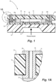
Fig. 1 is a cross-sectional view of a pressure sensor constructed in accordance with the subject disclosure, which is configured for absolute pressure sensing; -
Fig. 1A is an enlarged localized view fromFig. 1 showing the passivation layer deposited on the surfaces of the upper substrate; -
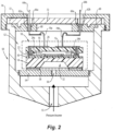
Fig. 2 is a cross-sectional view of the pressure sensor ofFig. 1 packaged in a housing assembly; -
Fig. 3 is a cross-sectional view of a pressure sensor constructed in accordance with the subject disclosure, which is configured for differential pressure sensing; -
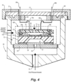
Fig. 4 is a cross-sectional view of the pressure sensor ofFig. 3 packaged in a housing assembly; -
Fig. 5 is a cross-sectional view of another pressure sensor constructed in accordance with the subject disclosure, which is configured for absolute pressure sensing; -
Fig. 6 is a cross-sectional view of the pressure sensor ofFig. 5 packaged in a housing assembly, having a first arrangement of bonding wires; -
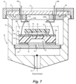
Fig. 7 is a cross-sectional view of the pressure sensor ofFig. 5 packaged in a housing assembly, having a second arrangement of bonding wires; -
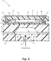
Fig. 8 is a cross-sectional view of the pressure sensor ofFig. 1 with a pedestal substrate added as a stress buffer; and -
Fig. 9 is a cross-sectional view of the pressure sensor ofFig. 8 packaged in a housing assembly. - Referring now to the drawings wherein like reference numeral identify similar features or components of the subject disclosure, there is illustrated in
Fig. 1 , a high-temperature pressure sensor constructed in accordance with an embodiment of the subject disclosure and designated generally byreference numeral 10.Pressure sensor 10 is a MEMS device fabricated as a die in a wafer batch process. Those skilled in the art will readily appreciate that this provides a significant manufacturing cost benefit. - Referring to
Fig. 1 ,pressure sensor 10 includes anupper substrate 12, alower substrate 14 bonded to theupper substrate 12 by way of a glass frit 16 so as to define a hermetically sealedpressure sensing chamber 18 between the two substrates. The upper andlower substrates - A piezo-
resistive diaphragm 20 is operatively associated with thepressure chamber 18 for converting a mechanical stress to an electrical signal indicative of a sensed pressure. Thediaphragm 20 has at least a piezo-resistive upper layer thereon made from a single crystal silicon material or a polysilicon material. Alternatively, thediaphragm 20 may be made entirely from a single crystal silicon material or a polysilicon material. - A patterned
metallic layer 22 is deposited between theupper substrate 12 and thelower substrate 14 outboard from the glass frit 16. Themetallic layer 22 is electrically connected to thediaphragm 20 by way ofmetal connectors conductive bond pad 26 that is associated with theupper substrate 12. More particularly, theconductive bond pad 26, which his deposited on the top surface of theupper substrate 12 extends through a series of passages orvias 28 that are outboard from thepressure chamber 18, so as to connect with themetallic layer 22. As best seen inFig. 1A , apassivation layer 25 is deposited around all the surfaces of theupper substrate 12 associated with thebond pad 26, including thevias 28. - The patterned
metallic layer 22 has a melting temperature that is less than the bonding temperature of the glass frit 16. Thus, it will advantageously melt and form a conductive path between thebond pad 26 and theconnectors glass frit 16 begins to melt. - Preferably, the patterned
layer 22 is a gold-tin alloy (AuSn) which will begin to melt at 280°C and theglass frit 16 is formed from a material that has a bonding temperature of about 400°C. These dual bonding materials will achieve both hermetic vacuum sealing and electrical connection. More particularly, the glass frit bonding achieves the vacuum and the AuSn bonding achieves the electrical connection. - Adhesion and barrier layers are preferably associated with piezo-
resistive diaphragm 20 and the patterned AuSn layer. The barrier layer could be Nickel (Ni) and the adhesion layer could be Chromium (Cr) or Zirconium (Zr). Preferably, adielectric insulation layer 30 is deposited on the top surface of the lower substrate, beneath the diaphragm, and theconnectors -
Pressure sensor 10 is adapted and configured to sense an absolute pressure. More particularly, there is a recessedcavity 32 etched into the bottom surface of thelower substrate 14 for pressure income. The incoming pressure exerts a force on thesubstrate 14, within thecavity 32, below thediaphragm 20. This causes thediaphragm 20 to deflect, which in turn generates a mechanical stress on the piezo-resistive surface layer of thediaphragm 20. More particularly, the piezo-resistive surface layer defines a Wheastone bridge circuit that converts the mechanical stress to an electrical signal indicative of an absolute pressure measurement. - Referring now to
Fig. 2 , thepressure sensor 10 is packaged with ahousing 50, which his preferably made from a stainless steel material. Thehousing 50 is generally cylindrical in shape and has aninterior cavity 52 for receiving thepressure sensor 10. More particularly, there is a base 54 for supporting thesensor 10 within theinterior cavity 52 ofhousing 50. Thebase 54 has a disc-like shape and is made of Kovar° (i.e., an alloy of nickel, cobalt and iron) or a similar alloy, and it is threaded into thecavity 52 and subsequently spot welded or brazed in place during assembly to make a sealed connection. Acentral port 56 extends through the base 54 to communicate with the recessedcavity 32 etched into the bottom surface of thelower substrate 14. Thecentral port 56 communicates with apressure port 55 formed in the bottom ofhousing 50. - Once the
base 54 is secured, thepressure sensor 10 is bonded to the upper surface of thereof by asecond glass frit 58, which has a bonding temperature that is lower than the bonding temperature of theglass frit 16 that hermetically bonds theupper substrate 12 to thelower substrate 14 during the die fabrication process. Thus, during package assembly, thefirst glass frit 16 will not reflow. It should be understood that the maximum operating temperature of the packaged sensor assembly will be effectively limited by the bonding temperature of thesecond glass frit 58. However, by proper material selection this temperature can withstand operating temperatures of 350°C or more. Moreover, because the package assembly is constructed from materials, such as Kovar® and stainless steel, it can tolerate operating temperatures of 350°C or more without concern. - After securing the
pressure sensor 10 to the supporting surface of thebase 54, astainless steel ring 60 is welded to the top of thehousing 50. Thering 60 has a pair of throughbores electrical connection pins Glass insulators 66a, 66b support thepins bores - A
central access port 68 is formed in thering 60 to enable electrical connection of the connector pins 64a, 64b to theconductive bond pad 26 on theupper substrate 12 by way ofbond wires steel spacer disc 72 is installed abovering 60 to close thecentral access port 68 in thedisc 60. Thereafter, afinal ring clamp 74 is threaded to the top of thehousing 50 to secure all of the packaging components of together and finish the assembly. It is envisioned that theinterior cavity 52 ofhousing 50 could be filled with filling material, such as Ecofoam®, to stabilize thebonding wires - Referring now to
Fig. 3 , there is illustrated another embodiment of a high-temperature pressure sensor designated generally byreference numeral 100, that is substantially identical to thepressure sensor 10 described above and shown inFigs. 1 and2 , except thatpressure sensor 100 is adapted and configured to sense a differential pressure. Thus, in addition to the recessedcavity 32 etched into the bottom surface of thelower substrate 14 for pressure income, there is apressure port 15 formed in theupper substrate 12 providing direct communication with thepressure chamber 18 for a second incoming pressure. Accordingly, thestainless steel housing 50 within whichpressure sensor 100 is packaged has asecond pressure port 150 provided in a side wall thereof, as shown inFig. 4 . - Referring now to
Fig. 5 , there is shown another high-temperature pressure sensor constructed in accordance with the subject disclosure, which is configured for absolute pressure sensing and is designated generally byreference numeral 200.Pressure sensor 200 is similar topressure sensor 10, but it includes a smallerupper substrate 112 that is electrically bonded to theconnectors lower substrate 14 byseparate bonding wires bond wires conductive bond pad 126 on theupper substrate 112 and theconnectors lower substrate 14. -
Fig. 6 shows thepressure sensor 200 packaged within astainless steel housing 50 in the same manner as described above with respect topressure sensor 10. In this regard,bond wires bond pad 126 onupper substrate 112 toconnector pins central access port 68 in thedisc 60. -
Fig. 7 also shows thepressure sensor 200 packaged within astainless steel housing 50, but in this embodiment, theelectrical connectors lower substrate 14 are directly connected to the connector pins 64a, 64b by way ofbonding wires upper substrate 112. However, this is a slightly more difficult assembly process, given the size and location ofcentral access port 68. - Referring to
Fig. 8 , there is illustrated the high-temperature pressure sensor 10 ofFig. 1 , wherein acompliant pedestal substrate 80 with apressure port 82 is additionally bonded to a bottom surface of thelower substrate 14 by way of aglass frit 84.Glass frit 84 has a bonding temperature equal to the bonding temperature of theglass frit 16 used to bond theupper substrate 12 to thelower substrate 14. As shown inFig. 9 , for packaging, aglass frit 86 is used to bond thepedestal 80 to the support surface if the base 54 inhousing 50.Glass frit 86 has a lower bonding temperature than glass frits 16 and 84. - While the subject disclosure has been shown and described with reference to preferred embodiments, those skilled in the art will readily appreciate that changes and/or modifications may be made thereto without departing from the scope of the subject disclosure.
Claims (15)
- A packaged pressure sensor assembly comprising:a) a pressure sensor (100, 200) including an upper substrate and a lower substrate bonded to one another by way of a first glass frit having a first bonding temperature, so as to define a hermetically sealed pressure sensing chamber therebetween; andb) a housing defining an internal cavity having a base with a support surface for supporting the pressure sensor (100, 200), wherein the pressure sensor (100, 200) is bonded to the support surface of the base by a second glass frit having a second bonding temperature that is lower than the first bonding temperature.
- The packaged pressure sensor assembly of Claim 1, wherein a diaphragm is operatively associated with the pressure chamber for converting a mechanical stress to an electrical signal indicative of a sensed pressure.
- The packaged pressure sensor assembly of Claim 2, wherein the pressure sensor (100, 200) and the housing are adapted and configured to sense an absolute pressure, or wherein the pressure sensor (100, 200) and the housing are adapted and configured to sense a differential pressure.
- The packaged pressure sensor assembly of Claim 2, wherein the housing includes a pair of electrical connectors for electrically communicating with the diaphragm.
- The packaged pressure sensor assembly of Claim 4, wherein bonding wires extend between the electrical connectors of the housing and a conductive bond pad associated with the upper substrate, and wherein the conductive bond pad communicates with electrical conductors connected to the diaphragm by way of a metallic layer deposited between the upper and lower substrates outboard from the first glass frit, or
wherein bonding wires extend between the electrical connectors of the housing and a conductive bond pad associated with the upper substrate, and wherein the conductive bond pad communicates with electrical conductors connected to the diaphragm by way of separate bonding wires outboard from the first glass frit, or wherein bonding wires extend between the electrical connectors of the housing and electrical conductors connected to the diaphragm outboard from the first glass frit. - The packaged pressure sensor assembly of Claim 4, wherein the lower substrate of the pressure sensor (100, 200) is bonded to a compliant pedestal substrate by way of another glass frit having a bonding temperature equal to the bonding temperature of the first glass frit.
- The packaged pressure sensor assembly of Claim 5, wherein the metallic layer has a melting temperature that is less than the first bonding temperature.
- The packaged pressure sensor assembly of Claim 9, wherein the metallic layer is formed from an alloy having a melting temperature that is less than the first bonding temperature, and optionally wherein the metallic layer is a gold alloy.
- The packaged pressure sensor assembly of Claim 2, wherein the diaphragm has at least a piezo-resistive layer thereon made from a single silicon material or a polysilicon material.
- The packaged pressure sensor assembly of any preceding Claim, wherein the housing is formed from stainless steel and the base is formed from an alloy of nickel, cobalt and iron.
- A pressure sensor (100, 200) comprising:a) an upper substrate;b) a lower substrate bonded to the upper substrate by way of a glass frit so as to define a hermetically sealed pressure sensing chamber therebetween;c) a diaphragm operatively associated with the pressure chamber for converting a mechanical stress to an electrical signal indicative of a sensed pressure; andd) a metallic layer deposited between the upper substrate and the lower substrate outboard from the glass frit, wherein the metallic layer is electrically connected to the diaphragm and to a conductive bond pad associated with the upper substrate.
- The pressure sensor of Claim 11, which is adapted and configured to sense an absolute pressure, or which is adapted and configured to sense a differential pressure.
- The pressure sensor of Claim 11 or 12, wherein the lower substrate is bonded to a compliant pedestal substrate by way of another glass frit having a bonding temperature that is equal to a bonding temperature of the glass frit between the upper and lower substrates.
- The pressure sensor of any of Claims 11 to 13, wherein the patterned metallic layer is a gold alloy having a melting temperature that is less than the bonding temperature of the glass frits.
- The pressure sensor of any of Claims 11 to 14, wherein the diaphragm has at least a piezo-resistive layer thereon made from a single silicon material or a polysilicon material.
Applications Claiming Priority (1)
| Application Number | Priority Date | Filing Date | Title |
|---|---|---|---|
| US18/118,809 US20240302237A1 (en) | 2023-03-08 | 2023-03-08 | High temperature piezo-resistive pressure sensor and packaging assembly therefor |
Publications (2)
| Publication Number | Publication Date |
|---|---|
| EP4428091A2 true EP4428091A2 (en) | 2024-09-11 |
| EP4428091A3 EP4428091A3 (en) | 2024-12-18 |
Family
ID=90363701
Family Applications (1)
| Application Number | Title | Priority Date | Filing Date |
|---|---|---|---|
| EP24161954.3A Pending EP4428091A3 (en) | 2023-03-08 | 2024-03-07 | High temperature piezo-resistive pressure sensor and packaging assembly therefor |
Country Status (2)
| Country | Link |
|---|---|
| US (1) | US20240302237A1 (en) |
| EP (1) | EP4428091A3 (en) |
Families Citing this family (2)
| Publication number | Priority date | Publication date | Assignee | Title |
|---|---|---|---|---|
| US12038340B2 (en) * | 2021-12-16 | 2024-07-16 | Whirlpool Corporation | Sensor assembly for vacuum insulated structure |
| EP4729911A1 (en) * | 2024-10-21 | 2026-04-22 | Kistler Holding AG | Piezoresistive pressure sensor and method of manufacturing such a piezoresistive pressure sensor |
Family Cites Families (4)
| Publication number | Priority date | Publication date | Assignee | Title |
|---|---|---|---|---|
| US5600071A (en) * | 1995-09-05 | 1997-02-04 | Motorola, Inc. | Vertically integrated sensor structure and method |
| US7775119B1 (en) * | 2009-03-03 | 2010-08-17 | S3C, Inc. | Media-compatible electrically isolated pressure sensor for high temperature applications |
| US9010190B2 (en) * | 2012-04-20 | 2015-04-21 | Rosemount Aerospace Inc. | Stress isolated MEMS structures and methods of manufacture |
| US10549982B2 (en) * | 2016-02-15 | 2020-02-04 | Stmicroelectronics S.R.L. | Pressure sensor encapsulated in elastomeric material, and system including the pressure sensor |
-
2023
- 2023-03-08 US US18/118,809 patent/US20240302237A1/en active Pending
-
2024
- 2024-03-07 EP EP24161954.3A patent/EP4428091A3/en active Pending
Also Published As
| Publication number | Publication date |
|---|---|
| EP4428091A3 (en) | 2024-12-18 |
| US20240302237A1 (en) | 2024-09-12 |
Similar Documents
| Publication | Publication Date | Title |
|---|---|---|
| US5515732A (en) | Capacitive pressure sensor and reference with stress isolating pedestal | |
| US6351996B1 (en) | Hermetic packaging for semiconductor pressure sensors | |
| US6346742B1 (en) | Chip-scale packaged pressure sensor | |
| CN102341685B (en) | Media-compatible electrically isolated pressure sensor for high temperature applications | |
| EP0202786B1 (en) | Piezoresistive pressure transducer | |
| US6450039B1 (en) | Pressure sensor and method of manufacturing the same | |
| US5157972A (en) | Pressure sensor with high modules support | |
| US20240302237A1 (en) | High temperature piezo-resistive pressure sensor and packaging assembly therefor | |
| US20130214370A1 (en) | System and method for minimizing deflection of a membrance of an absolute pressure sensor | |
| JP2010504529A (en) | Transmitter for use in harsh environments | |
| JP2012211869A (en) | Pressure sensor device | |
| US11994440B2 (en) | High temperature protected wire bonded sensors | |
| US7698951B2 (en) | Pressure-sensor apparatus | |
| EP2725334B1 (en) | A pressure sensor having a membrane and a method for fabricating the same | |
| US10254186B2 (en) | Pressure sensor | |
| EP0405633B1 (en) | Pressure/Differential measuring device | |
| US20250256956A1 (en) | Method for Fabricating a Hermetically Sealed Contact and Hermetically Sealed Contact | |
| CN118243263B (en) | Pressure sensing module, pressure sensor and electronic equipment | |
| CN118089999B (en) | Pressure sensor, pressure sensing device and electronic device | |
| JP2012225875A (en) | Pressure sensor |
Legal Events
| Date | Code | Title | Description |
|---|---|---|---|
| PUAI | Public reference made under article 153(3) epc to a published international application that has entered the european phase |
Free format text: ORIGINAL CODE: 0009012 |
|
| STAA | Information on the status of an ep patent application or granted ep patent |
Free format text: STATUS: THE APPLICATION HAS BEEN PUBLISHED |
|
| AK | Designated contracting states |
Kind code of ref document: A2 Designated state(s): AL AT BE BG CH CY CZ DE DK EE ES FI FR GB GR HR HU IE IS IT LI LT LU LV MC ME MK MT NL NO PL PT RO RS SE SI SK SM TR |
|
| PUAL | Search report despatched |
Free format text: ORIGINAL CODE: 0009013 |
|
| AK | Designated contracting states |
Kind code of ref document: A3 Designated state(s): AL AT BE BG CH CY CZ DE DK EE ES FI FR GB GR HR HU IE IS IT LI LT LU LV MC ME MK MT NL NO PL PT RO RS SE SI SK SM TR |
|
| RIC1 | Information provided on ipc code assigned before grant |
Ipc: B81B 3/00 20060101AFI20241113BHEP |
|
| STAA | Information on the status of an ep patent application or granted ep patent |
Free format text: STATUS: REQUEST FOR EXAMINATION WAS MADE |
|
| 17P | Request for examination filed |
Effective date: 20250604 |