EP4428069A1 - Positioning device and system - Google Patents
Positioning device and system Download PDFInfo
- Publication number
- EP4428069A1 EP4428069A1 EP22891820.7A EP22891820A EP4428069A1 EP 4428069 A1 EP4428069 A1 EP 4428069A1 EP 22891820 A EP22891820 A EP 22891820A EP 4428069 A1 EP4428069 A1 EP 4428069A1
- Authority
- EP
- European Patent Office
- Prior art keywords
- bearing member
- driving
- energy storage
- storage cabinet
- pushing
- Prior art date
- Legal status (The legal status is an assumption and is not a legal conclusion. Google has not performed a legal analysis and makes no representation as to the accuracy of the status listed.)
- Granted
Links
Images


Classifications
-
- B—PERFORMING OPERATIONS; TRANSPORTING
- B65—CONVEYING; PACKING; STORING; HANDLING THIN OR FILAMENTARY MATERIAL
- B65G—TRANSPORT OR STORAGE DEVICES, e.g. CONVEYORS FOR LOADING OR TIPPING, SHOP CONVEYOR SYSTEMS OR PNEUMATIC TUBE CONVEYORS
- B65G35/00—Mechanical conveyors not otherwise provided for
- B65G35/06—Mechanical conveyors not otherwise provided for comprising a load-carrier moving along a path, e.g. a closed path, and adapted to be engaged by any one of a series of traction elements spaced along the path
-
- H—ELECTRICITY
- H01—ELECTRIC ELEMENTS
- H01M—PROCESSES OR MEANS, e.g. BATTERIES, FOR THE DIRECT CONVERSION OF CHEMICAL ENERGY INTO ELECTRICAL ENERGY
- H01M10/00—Secondary cells; Manufacture thereof
- H01M10/04—Construction or manufacture in general
- H01M10/0404—Machines for assembling batteries
-
- B—PERFORMING OPERATIONS; TRANSPORTING
- B65—CONVEYING; PACKING; STORING; HANDLING THIN OR FILAMENTARY MATERIAL
- B65G—TRANSPORT OR STORAGE DEVICES, e.g. CONVEYORS FOR LOADING OR TIPPING, SHOP CONVEYOR SYSTEMS OR PNEUMATIC TUBE CONVEYORS
- B65G43/00—Control devices, e.g. for safety, warning or fault-correcting
-
- F—MECHANICAL ENGINEERING; LIGHTING; HEATING; WEAPONS; BLASTING
- F16—ENGINEERING ELEMENTS AND UNITS; GENERAL MEASURES FOR PRODUCING AND MAINTAINING EFFECTIVE FUNCTIONING OF MACHINES OR INSTALLATIONS; THERMAL INSULATION IN GENERAL
- F16M—FRAMES, CASINGS OR BEDS OF ENGINES, MACHINES OR APPARATUS, NOT SPECIFIC TO ENGINES, MACHINES OR APPARATUS PROVIDED FOR ELSEWHERE; STANDS; SUPPORTS
- F16M11/00—Stands or trestles as supports for apparatus or articles placed thereon ; Stands for scientific apparatus such as gravitational force meters
- F16M11/02—Heads
- F16M11/04—Means for attachment of apparatus; Means allowing adjustment of the apparatus relatively to the stand
- F16M11/043—Allowing translations
- F16M11/045—Allowing translations adapted to left-right translation movement
-
- F—MECHANICAL ENGINEERING; LIGHTING; HEATING; WEAPONS; BLASTING
- F16—ENGINEERING ELEMENTS AND UNITS; GENERAL MEASURES FOR PRODUCING AND MAINTAINING EFFECTIVE FUNCTIONING OF MACHINES OR INSTALLATIONS; THERMAL INSULATION IN GENERAL
- F16M—FRAMES, CASINGS OR BEDS OF ENGINES, MACHINES OR APPARATUS, NOT SPECIFIC TO ENGINES, MACHINES OR APPARATUS PROVIDED FOR ELSEWHERE; STANDS; SUPPORTS
- F16M11/00—Stands or trestles as supports for apparatus or articles placed thereon ; Stands for scientific apparatus such as gravitational force meters
- F16M11/02—Heads
- F16M11/18—Heads with mechanism for moving the apparatus relatively to the stand
-
- F—MECHANICAL ENGINEERING; LIGHTING; HEATING; WEAPONS; BLASTING
- F16—ENGINEERING ELEMENTS AND UNITS; GENERAL MEASURES FOR PRODUCING AND MAINTAINING EFFECTIVE FUNCTIONING OF MACHINES OR INSTALLATIONS; THERMAL INSULATION IN GENERAL
- F16M—FRAMES, CASINGS OR BEDS OF ENGINES, MACHINES OR APPARATUS, NOT SPECIFIC TO ENGINES, MACHINES OR APPARATUS PROVIDED FOR ELSEWHERE; STANDS; SUPPORTS
- F16M11/00—Stands or trestles as supports for apparatus or articles placed thereon ; Stands for scientific apparatus such as gravitational force meters
- F16M11/42—Stands or trestles as supports for apparatus or articles placed thereon ; Stands for scientific apparatus such as gravitational force meters with arrangement for propelling the support stands on wheels
- F16M11/425—Stands or trestles as supports for apparatus or articles placed thereon ; Stands for scientific apparatus such as gravitational force meters with arrangement for propelling the support stands on wheels along guiding means
-
- F—MECHANICAL ENGINEERING; LIGHTING; HEATING; WEAPONS; BLASTING
- F16—ENGINEERING ELEMENTS AND UNITS; GENERAL MEASURES FOR PRODUCING AND MAINTAINING EFFECTIVE FUNCTIONING OF MACHINES OR INSTALLATIONS; THERMAL INSULATION IN GENERAL
- F16M—FRAMES, CASINGS OR BEDS OF ENGINES, MACHINES OR APPARATUS, NOT SPECIFIC TO ENGINES, MACHINES OR APPARATUS PROVIDED FOR ELSEWHERE; STANDS; SUPPORTS
- F16M7/00—Details of attaching or adjusting engine beds, frames, or supporting-legs on foundation or base; Attaching non-moving engine parts, e.g. cylinder blocks
-
- H—ELECTRICITY
- H01—ELECTRIC ELEMENTS
- H01M—PROCESSES OR MEANS, e.g. BATTERIES, FOR THE DIRECT CONVERSION OF CHEMICAL ENERGY INTO ELECTRICAL ENERGY
- H01M10/00—Secondary cells; Manufacture thereof
- H01M10/04—Construction or manufacture in general
-
- B—PERFORMING OPERATIONS; TRANSPORTING
- B65—CONVEYING; PACKING; STORING; HANDLING THIN OR FILAMENTARY MATERIAL
- B65G—TRANSPORT OR STORAGE DEVICES, e.g. CONVEYORS FOR LOADING OR TIPPING, SHOP CONVEYOR SYSTEMS OR PNEUMATIC TUBE CONVEYORS
- B65G2811/00—Indexing codes relating to common features for more than one conveyor kind or type
- B65G2811/09—Driving means for the conveyors
-
- Y—GENERAL TAGGING OF NEW TECHNOLOGICAL DEVELOPMENTS; GENERAL TAGGING OF CROSS-SECTIONAL TECHNOLOGIES SPANNING OVER SEVERAL SECTIONS OF THE IPC; TECHNICAL SUBJECTS COVERED BY FORMER USPC CROSS-REFERENCE ART COLLECTIONS [XRACs] AND DIGESTS
- Y02—TECHNOLOGIES OR APPLICATIONS FOR MITIGATION OR ADAPTATION AGAINST CLIMATE CHANGE
- Y02E—REDUCTION OF GREENHOUSE GAS [GHG] EMISSIONS, RELATED TO ENERGY GENERATION, TRANSMISSION OR DISTRIBUTION
- Y02E60/00—Enabling technologies; Technologies with a potential or indirect contribution to GHG emissions mitigation
- Y02E60/10—Energy storage using batteries
-
- Y—GENERAL TAGGING OF NEW TECHNOLOGICAL DEVELOPMENTS; GENERAL TAGGING OF CROSS-SECTIONAL TECHNOLOGIES SPANNING OVER SEVERAL SECTIONS OF THE IPC; TECHNICAL SUBJECTS COVERED BY FORMER USPC CROSS-REFERENCE ART COLLECTIONS [XRACs] AND DIGESTS
- Y02—TECHNOLOGIES OR APPLICATIONS FOR MITIGATION OR ADAPTATION AGAINST CLIMATE CHANGE
- Y02P—CLIMATE CHANGE MITIGATION TECHNOLOGIES IN THE PRODUCTION OR PROCESSING OF GOODS
- Y02P70/00—Climate change mitigation technologies in the production process for final industrial or consumer products
- Y02P70/50—Manufacturing or production processes characterised by the final manufactured product
Definitions
- the present application relates to the field of battery production devices, specifically relates to a positioning apparatus and system.
- an energy storage cabinet In the production process of an energy storage cabinet production line of batteries, it basically relies on manual operation.
- an energy storage cabinet is manually placed on a forklift, and transported to the corresponding position through the forklift for other production processes.
- the present application provides a positioning apparatus and system.
- the positioning apparatus may solve the problems in the prior art that an energy storage cabinet is tedious in transportation, heavy in installation, low in control precision, low in working efficiency and the like.
- the present application provides a positioning apparatus; and the positioning apparatus includes: a rotating member which is arranged on a base.
- a bearing member is arranged on the base through the rotating member.
- a first driving mechanism is used for applying a force to the bearing member from a first side of the bearing member.
- a second driving mechanism is used for applying a force to the bearing member from a second side, adjacent to the first side, of the bearing member.
- two first driving mechanisms are provided and are respectively arranged on the first side and a third side, opposite to the first side, of the bearing member.
- the first driving mechanisms are used for applying a force to the bearing member from the first side and the third side respectively.
- the two first driving mechanisms are provided, so that the force can be applied to the bearing member from the first side and the third side, opposite to each other, of the bearing member through the two first driving mechanisms, and the position of the bearing member can be adjusted from the first side and the third side, opposite to each other, of the bearing member.
- each first driving mechanism includes a first driving member, a lead screw and a first pushing member.
- the driving member and the first pushing member are connected to two ends of the lead screw respectively, the first driving member is fixed to the base, and the first pushing member is located between the bearing member and the first driving member.
- the lead screw is driven by the first driving member to rotate so as to drive the first pushing member to move in the axis direction of the lead screw; and the first pushing member pushes the bearing member when moving.
- the first driving members drive the lead screws to rotate, the lead screws rotate to drive the first pushing members to move in the axis direction of the lead screws, and the first pushing members push the bearing member when moving, so that the force can be applied to the bearing member through the first pushing members, and the position of the bearing member is adjusted.
- the positioning apparatus further includes a clamping mechanism;
- the clamping mechanism includes: two supports which are arranged on the first side and the third side respectively, the supports being fixed to the lead screws.
- Two clamping plates are fixed to the supports respectively, arranged in the direction facing the bearing member and used for clamping the energy storage cabinet borne by the bearing member.
- the lead screws rotate to drive the supports to move in the axis direction of the lead screws, then the distance between the two supports is increased or decreased, and therefore the two clamping plates clamp the energy storage cabinet.
- a specific structural form of the clamping mechanism is provided, and the energy storage cabinet borne on the bearing member can be clamped through the clamping plate in these embodiments, so that the clamping surface is uniformly stressed.
- the clamping mechanism further includes: at least two third driving mechanisms fixed to the supports; at least two second pushing members which are respectively connected to the third driving mechanisms and arranged in the direction facing the bearing member, where the two third driving mechanisms are used for driving the two second pushing members respectively to reciprocate in the direction of the second side, so that the two second pushing members clamp the energy storage cabinet from two opposite sides of the energy storage cabinet; at least two fourth driving mechanisms which are fixed to the supports and respectively connected to the second pushing members, where the two fourth driving mechanisms are used for driving the two second pushing members respectively to reciprocate in the direction of the first side of the bearing member, the second pushing members apply a force to the energy storage cabinet when moving, and the energy storage cabinet apply a friction force to the bearing member, thus pushing the energy storage cabinet to a second preset position.
- the force can be applied to the energy storage cabinet placed on the bearing member so as to adjust the energy storage cabinet to the second preset position, so that when the energy storage cabinet is not accurately located at the second preset position, the position of the energy storage cabinet can be finely adjusted, and then the energy storage cabinet can be accurately located at the second preset position.
- the second driving mechanism includes a third pushing member and a second driving member.
- the third pushing member is connected to the second driving member; the second driving member is fixed to the base; the second driving member is used for driving the third pushing member to move; and the third pushing member applies a force to the bearing member when moving.
- the second driving member drives the third pushing member to move
- the third pushing member applies a force to the bearing member when moving, so that the position of the bearing member is adjusted in a mode that the second driving member drives the third pushing member.
- the bearing member is provided with a first position-limiting mechanism
- the base is provided with a second position-limiting mechanism.
- the bearing member moves to a third preset position, the bearing member is limited on the base through the cooperation of the first position-limiting mechanism and the second position-limiting mechanism, and therefore relative displacement between the bearing member and the base is avoided.
- a specific fixing mode that the bearing member and the base are detachably fixed together is provided according to this design, thus the connecting strength of the bearing member and the base can be improved, and relative displacement of the bearing member and the base is avoided.
- the positioning apparatus further includes a fifth driving mechanism.
- the fifth driving mechanism is connected to the second position-limiting mechanism and used for driving the second position-limiting mechanism to move to the first position-limiting mechanism to cooperate with the first position-limiting mechanism when the bearing member moves to the third preset position.
- the fifth driving mechanism drives the second position-limiting mechanism to move to the first position-limiting mechanism to cooperate with the first position-limiting mechanism, so that automatic matching of the first position-limiting mechanism and the second position-limiting mechanism is achieved, manual operation is avoided, and manpower can be saved.
- the positioning apparatus further includes a sensor, and the sensor is fixed to the base and used for detecting the position of the bearing member.
- the sensor is connected with a peripheral device, and therefore the peripheral device can place the energy storage cabinet on the bearing member according to the position, detected by the sensor, of the bearing member.
- the sensor is connected with the peripheral device, so that the peripheral device places the energy storage cabinet on the bearing member according to the position, detected by the sensor, of the bearing member, automatic operation of the peripheral device can be achieved, manpower and material resources can be saved, and misoperation caused by manual errors can be avoided.
- the rotating member includes universal balls arranged on the base at intervals.
- the rotating member in these embodiments can be universal balls; a specific structural form of the rotating member is provided; and the universal balls are simple in installation mode and low in cost.
- the present application further provides a positioning system, including the positioning apparatus according to any one of the above embodiments, and the peripheral device.
- the peripheral device is used for placing the energy storage cabinet on the bearing member.
- the positioning system includes the positioning apparatus according to any one of the above embodiments. Therefore, according to these embodiments, the positioning apparatus can bear the energy storage cabinet in the production process of an energy storage production line of batteries, which can avoid the problems of tedious transportation, heavy installation, high labor intensity, low control accuracy and low production efficiency caused by manually placing the energy storage cabinet, and the production efficiency of the energy storage production line of batteries can be improved.
- the positioning apparatus can bear the energy storage cabinet in the production process of an energy storage production line of batteries, which can avoid the problems of tedious transportation, heavy installation, high labor intensity, low control accuracy and low production efficiency caused by manually placing the energy storage cabinet, and the production efficiency of the energy storage production line of batteries can be improved.
- the attached marks and numbers in the specific embodiments are as follows: 1-cabinet body; 2-metal frame; 3-metal panel; 4-cabinet door; 5-base; 51-sliding rails; 6-bearing member; 61-first side; 62-second side; 63-third side; 64-fourth side; 7-first driving mechanism; 71-lead screw; 72-first pushing member; 73-fixing block; 8-second driving mechanism; 81-third pushing mechanism; 82-second driving member; 9-clamping mechanism; 91-support; 92-clamping plate; 93-second pushing member; and 921-notch.
- a reference to "embodiment” herein means that a particular feature, mechanism, or characteristic described in conjunction with an embodiment may be included in at least one embodiment of the present application.
- the occurrence of the phrase in various places in the description does not necessarily refer to the same embodiment, nor is it an independent or alternative embodiment that is mutually exclusive with other embodiments. It is explicitly and implicitly understood by those skilled in the art that the embodiments described herein may be combined with other embodiments.
- a plurality of refers to more than two (including two), similarly, “a plurality of groups” refers to two or more groups (including two groups), and “a plurality of members” refers to more than two members (including two members).
- Power batteries are increasingly more widely used.
- Power batteries are not only used in energy storage power systems such as hydropower, thermal power, wind power and solar power stations, but also widely used in electric vehicles such as electric bicycles, electric motorcycles, and electric vehicles, as well as military equipment and aerospace and other fields.
- electric vehicles as well as military equipment and aerospace
- batteries have become the key to the sustainable development of the automotive industry.
- battery technology is an important factor in their development.
- an electric centering positioning mechanism including a centering positioning base plate, a centering positioning substrate and a working platform; a lifting cylinder is fixed to the centering positioning baseplate; the centering positioning substrate is arranged above the lifting cylinder; a working platform cover is arranged on the centering positioning substrate; two pairs of X-guide rails, two pairs of Y-guide rails, X-direction motors, Y-direction motors, X-direction synchronous belts, Y-direction synchronous belts, a X-direction centering module and a Y-direction centering module are arranged on the centering positioning substrate; one X-direction motor is mounted between each pair of X-guide rails; one Y-direction motor is mounted between each pair of Y-guide rails; the X-direction synchronous belts are mounted on the X-direction motor; the Y-direction synchronous belts are mounted on the Y-direction motors; the X-direction synchronous belts are mounted on
- the applicant has designed a positioning apparatus and system by in-depth research; and the positioning apparatus may solve the problems in the prior art that an energy storage cabinet is tedious in transportation, heavy in installation, low in control precision, low in working efficiency and the like in related technology.
- the batteries according to the present application consist of either a battery module or a battery cell.
- the batteries may include a lithium-ion secondary battery, a lithium-ion primary battery, a lithium-sulfur battery, a sodium-lithium-ion battery, a sodium-ion battery or a magnesium-ion battery, etc., which are not limited in these embodiments of the present application.
- These types of batteries may be used in a variety of electrical apparatuses.
- the electrical apparatuses may be vehicles, mobile phones, portable devices, laptops, ships, spacecraft, electric toys and power tools, and so on.
- the vehicle may be a fuel vehicle, a gas vehicle, or a new energy vehicle.
- the new energy vehicle may be an all-electric vehicle, a hybrid electric vehicle, an extended-range electric vehicle, or the like.
- the spacecraft includes an airplane, a rocket, a space shuttle, a spaceship, and the like.
- the electric toy includes a fixed or mobile electric toy, such as a game console, an electric car toy, an electric ship toy, and an electric aircraft toy.
- the electric tool includes a metal cutting electric tool, a grinding electric tool, an assembly electric tool, and a railway electric tool, such as an electric drill, an electric grinder, an electric wrench, an electric a screwdriver, an electric hammer, an impact drill, a concrete vibrator, and an electric planer.
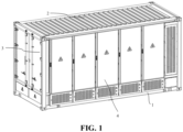
- FIG. 1 is a structure schematic diagram of an energy storage cabinet according to some embodiments of the present application.
- the energy storage cabinet includes a cabinet body 1, and the cabinet body 1 may be of a cuboid structure or a cube structure.
- the cabinet body 1 may be composed of a metal frame 2 and a metal panel 3.
- the metal frame 2 can be composed of a plurality of stand columns and cross beams connected between every two stand columns.
- a cabinet door 4 capable of being opened and closed is arranged in front of the cabinet body 1.
- a battery rack is arranged in the cabinet body 1, and a plurality of battery boxes are arranged on the battery rack.
- the battery boxes are energy storage units of the energy storage cabinet.
- the present application further provides a positioning apparatus; and as shown in FIG. 2, FIG. 2 is a structure schematic diagram of a positioning apparatus according to some embodiments of the present application.
- the positioning apparatus includes a base 5, a bearing member 6, a first driving mechanism 7 and a second driving mechanism 8.
- a rotating member is arranged on the base 5.
- the bearing member 6 is arranged on the base 5 through the rotating member.
- the first driving mechanism 7 is used for applying a force to the bearing member 6 from a first side 61 of the bearing member 6.
- the second driving mechanism 8 is used for applying a force to the bearing member 6 from a second side 62, adjacent to the first side 61, of the bearing member 6.
- the bearing member 6 When the bearing member 6 is subjected to force, a force is applied to the rotating member, and then the rotating member rotates in situ to drive the bearing member 6 to move; and when moving to a first preset position, the bearing member 6 is used for bearing an energy storage cabinet in the production process of an energy storage production line of batteries.
- the bearing member 6 may be a bearing plate used for bearing the energy storage cabinet.
- the force may be applied to the bearing member 6 from the first side 61 of the bearing member 6 through the first driving mechanism 7; the force is applied to the bearing member 6 from the second side 62, adjacent to the first side 61, of the bearing member 6 through the second driving mechanism 8, then the position of the bearing member 6 is adjusted, so that the bearing member 6 moves to a first preset position.
- the first preset position is not limited, and in practical application, the first preset position may be set according to the size and shape of the bearing member 6, the size and shape of the base 5 and the size and shape of the energy storage cabinet.
- the positioning apparatus can bear the energy storage cabinet in the production process of an energy storage production line of batteries, which can avoid the problems of tedious transportation, heavy installation, high labor intensity, low control accuracy and low production efficiency caused by manually placing the energy storage cabinet, and the production efficiency of the energy storage production line of batteries can be improved.
- two first driving mechanisms 7 are provided and are respectively arranged on the first side 61 and a third side 63, opposite to the first side 61 of the bearing member 6.
- the first driving mechanisms 7 are used for applying a force to the bearing member 6 from the first side 61 and the third side 63 respectively.
- two first driving mechanisms 7 are provided, so that the force can be applied to the bearing member 6 from the first side 61 and the third side 63, opposite to each other, of the bearing member 6 through the two first driving mechanisms 7, and the position of the bearing member 6 can be adjusted from the first side 61 and the third side 63, opposite to each other, of the bearing member 6.
- FIG. 3 is a structure schematic diagram of a first driving mechanism 7 according to some embodiments of the present application
- FIG. 4 is a structure schematic diagram of a first driving mechanism 7 in another direction according to some embodiments of the present application.
- each first driving mechanism 7 includes a first driving member, a lead screw 71 and a first pushing member 72.
- the driving member and the first pushing member 72 are connected to two ends of the lead screw 71 respectively, the first driving member is fixed to the base 5, and the first pushing member 72 is located between the bearing member 6 and the first driving member.
- the lead screw 71 is driven by the first driving member to rotate so as to drive the first pushing member 72 to move in the axis direction of the lead screw 71; and the first pushing member 72 pushes the bearing member 6 when moving.
- the first driving member may be a motor.
- the motor rotates to drive the lead screw 71 to rotate.
- the first pushing member 72 may be a pushing slide block.
- the first driving members drive the lead screws 71 to rotate, the lead screws 71 rotate to drive the first pushing members 72 to move in the axis direction of the lead screws 71, and the first pushing members 72 push the bearing member 6 when moving, so that the force can be applied to the bearing member 6 through the first pushing members 72, and the position of the bearing member 6 is adjusted.
- FIG. 5 is an amplification diagram of a mark A in FIG. 2 .
- the positioning apparatus further includes a clamping mechanism 9.
- the clamping mechanism 9 includes: two supports 91 which are arranged on the first side 61 of the bearing member 6 and the third side 63 of the bearing member respectively, and the supports 91 are fixed to the lead screws 71.
- Two clamping plates 92 are fixed to the supports 91 respectively, arranged in the direction facing the bearing member 6 and used for clamping the energy storage cabinet borne by the bearing member 6.
- the lead screws rotate to drive the supports 91 to move in the axis direction of the lead screws 71, then the distance between the two supports 91 is increased or decreased, and therefore the two clamping plates clamp the energy storage cabinet.
- each clamping mechanism 9 may include one clamping plate 92, and each clamping mechanism 9 may also include two clamping plates 92, three clamping plates 92 or four clamping plates 92 and the like, which are not listed here.
- the number of the clamping plates 92 may be set according to the size of the clamping plates 92 and the size of the energy storage cabinet.
- each first driving mechanism 7 further includes a fixing block 73 matched with the corresponding lead screw 71; the fixing blocks 73 are arranged on the lead screws 71 in a sleeving mode, and the clamping mechanisms 9 are fixed to the lead screws 71 through the fixing blocks 73.
- the lead screws 71 are driven by the first driving members to rotate so as to drive the fixing blocks 73 to move in the axis direction of the lead screws 71, and the fixing blocks 73 drive the clamping mechanisms 9 to move in the axis direction of the lead screws 71.
- the base 5 is provided with sliding rails 51.
- the clamping mechanisms 9 are arranged on the sliding rails 51 so that the clamping mechanisms 9 can move in the axis direction of the lead screws 71 along the sliding rails 51.
- the clamping mechanisms 9 may be stressed more evenly when moving in the axis direction of the lead screws 71 along the sliding rails 51.
- balls may be arranged in the sliding rails 51 so as to reduce the friction force between the clamping mechanisms 9 and the sliding rails 51.
- the clamping mechanisms 9 move in the axis direction of the lead screws 71 along the sliding rails 51 so that the sliding rails 51 can limit the movement path of the clamping mechanisms 9.
- the clamping mechanisms 9 are adopted to clamp the energy storage cabinet, so that in the production process of an energy storage production line of batteries, the energy storage cabinet can be clamped from two opposite sides of the energy storage cabinet through the clamping mechanisms 9, and relative displacement between the energy storage cabinet and the bearing member 6 is avoided. Because the distance between the two clamping plates 92 can be increased or decreased, the energy storage cabinets of different sizes can be adapted, and thus the positioning apparatus can have better compatibility.
- each clamping mechanism 9 further includes: at least two third driving mechanisms fixed to the supports 91; at least two second pushing members 93 which are respectively connected to the third driving mechanisms and arranged in the direction facing the bearing member 6, where the two third driving mechanisms are used for driving the two second pushing members 93 respectively to reciprocate in the direction of the second side 62, so that the two second pushing members 93 clamp the energy storage cabinet from two opposite sides of the energy storage cabinet; at least two fourth driving mechanisms which are fixed to the supports 91 and respectively connected to the second pushing members 93, where the two fourth driving mechanisms are used for driving the two second pushing members 93 respectively to reciprocate in the direction of the first side 61 of the bearing member 6, the second pushing members 93 apply a force to the energy storage cabinet when moving, and the energy storage cabinet apply a friction force to the bearing member 6 so as to push the energy storage cabinet to a second preset position.
- the clamping plates 92 may have notches 921, and the notches 921 are used as a motion track when the second thrusting members 93 reciprocate along the direction of the first side 61 under the drive of the fourth driving mechanisms.
- the second pushing members 93 reciprocate along the direction of the second side 62 under the drive of the third driving mechanism, the second pushing members can pass through the notches 921.
- each clamping mechanism 9 can include two second pushing members 93, and each clamping mechanism 9 can also include four second pushing members 93, six second pushing members 93 or eight second pushing members 93 and the like, which is not listed here.
- the number of the second pushing members 93 can be set according to the sizes of the second pushing members 93 and the size of the energy storage cabinet, so that the second pushing members 93 can clamp and push the energy storage cabinet to move.
- the second pushing members 93 in these embodiments can be pushing sliding blocks.
- the third driving mechanisms include first air cylinders fixed to the second pushing members 93.
- the second pushing members 93 are driven by the first air cylinders to reciprocate in the direction of the second side 62 of the bearing member 6, and therefore the two second pushing members 93 can clamp the energy storage cabinet from two opposite sides of the energy storage cabinet.
- the fourth driving mechanisms include second air cylinders fixed to the second pushing members 93.
- the second pushing members 93 are driven by the second air cylinders to reciprocate in the direction of first side 61 of the bearing member 6, and therefore the two second pushing members 93 can apply the force to the energy storage cabinet while clamping the energy storage cabinet.
- the energy storage cabinet applies the friction force to the bearing member 6, and the energy storage cabinet is pushed to a second preset position through the rotating member.
- the force may be applied to the energy storage cabinet placed on the bearing member 6 so that the energy storage cabinet can be adjusted to the second preset position, and therefore it can be guaranteed that when the energy storage cabinet is not accurately located at the second preset position, the position of the energy storage cabinet can be finely adjusted, and thus the energy storage cabinet can be accurately located at the second preset position.
- FIG. 6 is a structure schematic diagram of a second driving mechanism 8 according to some embodiments of the present application.
- the second driving mechanisms 8 include third pushing members 81 and second driving members 82.
- the third pushing members 81 are connected to the second driving members 82, the second driving members 82 are fixed to the base 5, the second driving members 82 are used for driving the third pushing members 81 to move, and the third pushing members 81 apply a force to the bearing member 6 when moving.
- the two second driving mechanisms 8 which are arranged on the second side 62 and the fourth side 64, opposite to the second side 62, of the bearing member 6 respectively; and the second driving mechanisms 8 are used for applying the force to the bearing member 6 from the second side 62 and the fourth side 64 correspondingly.
- the two second driving mechanisms 8 can apply the force to the bearing member 6 from the second side 62 and the fourth side 64, opposite to each other, of the bearing member 6, and therefore the position of the bearing member 6 can be adjusted from the second side 62 and the fourth side 64, opposite to each other, of the bearing member 6.
- the second driving members 82 drive the third pushing members 81 to move, the third pushing members 81 apply the force to the bearing member 6 when moving, and therefore the position of the bearing member 6 can be adjusted in the manner that the second driving members 82 drive the third pushing members 81.
- the second driving members 82 are third air cylinders, and the third pushing members 81 are pushing plates.
- the second driving members 82 are third air cylinders, and the third pushing members 81 are pushing plates.
- the bearing member 6 is provided with a first position-limiting mechanism
- the base 5 is provided with a second position-limiting mechanism.
- the bearing member 6 moves to a third preset position, the bearing member 6 is limited on the base 5 through cooperation of the first position-limiting mechanism and the second position-limiting mechanism, so that relative displacement between the bearing member 6 and the base 5 is avoided.
- the first position-limiting mechanism can be a positioning hole
- the second position-limiting mechanism can be a positioning pin
- the first position-limiting mechanism can be a positioning pin
- the second position-limiting mechanism can be a positioning hole
- a specific fixing mode for detachably fixing the bearing member 6 and the base 5 together is provided through this design, so the connecting strength of the bearing member 6 and the base 5 can be improved, and relative displacement between the bearing member 6 and the base 5 is avoided.
- the positioning apparatus further includes a fifth driving mechanism.
- the fifth driving mechanism is connected to the second position-limiting mechanism and used for driving the second position-limiting mechanism to move to the first position-limiting mechanism to cooperate with the first position-limiting mechanism when the bearing member 6 moves to the third preset position.
- the fifth driving mechanism may include a fourth air cylinder connected to the second position-limiting mechanism.
- the second position-limiting mechanism is driven by the fourth air cylinder to move, so that a specific structural form for driving the second position-limiting mechanism to move is provided, and the feasibility of this solution can be improved.
- the positioning apparatus further includes a floating plate.
- the floating plate is arranged on the bearing member 6 and used for bearing the energy storage cabinet, and the height of the energy storage cabinet can be increased through the floating plate.
- An elastic member can be arranged on the face, making contact with the energy storage cabinet, of the floating plate, and the energy storage cabinet makes elastic contact with the floating plate.
- the number of the floating plates in the embodiment may be set to be 3 but not limited to be 3, and the number of the floating plates may be designed according to the size and weight of the energy storage cabinet in practical application.
- the fifth driving mechanism drives the second position-limiting mechanism to move to the first position-limiting mechanism to cooperate with the first position-limiting mechanism, thus automatic matching of the first position-limiting mechanism and the second position-limiting mechanism can be achieved, manual operation is avoided, and manpower can be saved.
- the positioning apparatus further includes a sensor, and the sensor is fixed to the base 5 and used for detecting the position of the bearing member 6.
- the sensor is connected with a peripheral device, and therefore the peripheral device can place the energy storage cabinet on the bearing member 6 according to the position, detected by the sensor, of the bearing member 6.
- the senor is connected with the peripheral device, the peripheral device can place the energy storage cabinet on the bearing member 6 according to the position, detected by the sensor, of the bearing member 6, thus automatic operation of the peripheral device can be achieved, manpower and material resources can be saved, and misoperation caused by manual errors can be avoided.
- the rotating member includes universal balls arranged on the base 5 at intervals.
- the rotating member in these embodiments may be the universal balls, a specific structural form of the rotating member is provided, and the universal balls are simple in mounting mode and low in cost.
- the present application further provides a positioning apparatus.
- the positioning apparatus device includes: a rotating member arranged on a base 5.
- the bearing member 6 is arranged on the base 5 through the rotating member.
- the first driving mechanism 7 is used for applying a force to the bearing member 6 from a first side 61 of the bearing member 6.
- the second driving mechanism 8 is used for applying a force to the bearing member 6 from a second side 62, adjacent to the first side 61, of the bearing member 6.
- the rotating member 6 When the bearing member 6 is subjected to force, a force is applied to the rotating member, and then the rotating member rotates in situ to drive the bearing member 6 to move; and when moving to a first preset position, the bearing member 6 is used for bearing an energy storage cabinet in the production process of an energy storage production line of batteries.
- the rotating member includes universal balls arranged on the base 5 at intervals.
- the bearing member 6 may be a bearing plate used for bearing the energy storage cabinet.
- the force may be applied to the bearing member 6 from the first side 61 of the bearing member 6 through the first driving mechanism 7; the force is applied to the bearing member 6 from the second side 62, adjacent to the first side 61, of the bearing member 6 through the second driving mechanism 8, then the position of the bearing member 6 is adjusted, so that the bearing member 6 moves to a first preset position.
- the first preset position is not limited, and in practical application, the first preset position may be set according to the size and shape of the bearing member 6, the size and shape of the base 5 and the size and shape of the energy storage cabinet.
- Two first driving mechanisms 7 are provided and are respectively arranged on the first side 61 and a third side 63, opposite to the first side 61 of the bearing member 6.
- the first driving mechanisms 7 are used for applying a force to the bearing member 6 from the first side 61 and the third side 63 respectively.
- the positioning apparatus further includes two clamping mechanisms 9.
- the two clamping mechanisms 9 are respectively arranged on the first side 61 and the third side 63.
- the clamping mechanisms 9 are fixed to the first driving mechanisms 7.
- the first driving mechanisms 7 drive the clamping mechanisms 9 to move, then the distance between the two clamping mechanisms 9 is increased or decreased, and therefore the energy storage cabinet can be clamped.
- Each clamping mechanism 9 further includes: at least two third driving mechanisms fixed to the supports 91; at least two second pushing members 93 which are respectively connected to the third driving mechanisms and arranged in the direction facing the bearing member 6, where the two third driving mechanisms are used for driving the two second pushing members 93 respectively to reciprocate in the direction of the second side 62, so that the two second pushing members 93 clamp the energy storage cabinet from two opposite sides of the energy storage cabinet; at least two fourth driving mechanisms which are fixed to the supports 91 and respectively connected to the second pushing members 93, where the two fourth driving mechanisms are used for driving the two second pushing members 93 respectively to reciprocate in the direction of the first side 61 of the bearing member 6, the second pushing members 93 apply a force to the energy storage cabinet when moving, and the energy storage cabinet apply a friction force to the bearing member 6 so as to push the energy storage cabinet to a second preset position.
- the positioning apparatus further includes a sensor, and the sensor is fixed to the base 5 and used for detecting the position of the bearing member 6.
- the sensor is connected with a peripheral device, and therefore the peripheral device can place the energy storage cabinet on the bearing member 6 according to the position, detected by the sensor, of the bearing member 6.
- the positioning apparatus can bear the energy storage cabinet in the production process of an energy storage production line of batteries, which can avoid the problems of tedious transportation, heavy installation, high labor intensity, low control accuracy and low production efficiency caused by manually placing the energy storage cabinet, and the production efficiency of the energy storage production line of batteries can be improved.
- the present application further provides a positioning system.
- the positioning system in these embodiments includes the positioning apparatus according to any one of the above embodiments, and the peripheral device.
- the peripheral device is used for placing the energy storage cabinet on the bearing member.
- the positioning system includes the positioning apparatus according to any one of the above embodiments. Therefore, according to these embodiments, the positioning apparatus can bear the energy storage cabinet in the production process of an energy storage production line of batteries, which can avoid the problems of tedious transportation, heavy installation, high labor intensity, low control accuracy and low production efficiency caused by manually placing the energy storage cabinet, and the production efficiency of the energy storage production line of batteries can be improved.
Landscapes
- Engineering & Computer Science (AREA)
- General Engineering & Computer Science (AREA)
- Mechanical Engineering (AREA)
- Manufacturing & Machinery (AREA)
- Chemical & Material Sciences (AREA)
- Chemical Kinetics & Catalysis (AREA)
- Electrochemistry (AREA)
- General Chemical & Material Sciences (AREA)
- Battery Mounting, Suspending (AREA)
- Automatic Assembly (AREA)
Abstract
Description
- The present application claims priority to
Chinese Patent Application No. 202122790363.8 entitled "POSITIONING APPARATUS AND SYSTEM" and filed on November 15, 2021 - The present application relates to the field of battery production devices, specifically relates to a positioning apparatus and system.
- At present, in the production process of an energy storage cabinet production line of batteries, it basically relies on manual operation. For example, an energy storage cabinet is manually placed on a forklift, and transported to the corresponding position through the forklift for other production processes.
- Therefore, there are still problems such as low degree of automation and high manual manpower in the production of energy storage cabinets, which will lead to low production efficiency.
- The present application provides a positioning apparatus and system. The positioning apparatus may solve the problems in the prior art that an energy storage cabinet is tedious in transportation, heavy in installation, low in control precision, low in working efficiency and the like.
- In a first aspect, the present application provides a positioning apparatus; and the positioning apparatus includes: a rotating member which is arranged on a base. A bearing member is arranged on the base through the rotating member. A first driving mechanism is used for applying a force to the bearing member from a first side of the bearing member. A second driving mechanism is used for applying a force to the bearing member from a second side, adjacent to the first side, of the bearing member. When the bearing member is subjected to force, a force is applied to the rotating member, and then the rotating member rotates in situ to drive the bearing member to move; and when moving to a first preset position, the bearing member is used for bearing an energy storage cabinet in the production process of an energy storage production line of batteries.
- In some embodiments, two first driving mechanisms are provided and are respectively arranged on the first side and a third side, opposite to the first side, of the bearing member. The first driving mechanisms are used for applying a force to the bearing member from the first side and the third side respectively.
- In these embodiments, the two first driving mechanisms are provided, so that the force can be applied to the bearing member from the first side and the third side, opposite to each other, of the bearing member through the two first driving mechanisms, and the position of the bearing member can be adjusted from the first side and the third side, opposite to each other, of the bearing member.
- In some embodiments, each first driving mechanism includes a first driving member, a lead screw and a first pushing member. The driving member and the first pushing member are connected to two ends of the lead screw respectively, the first driving member is fixed to the base, and the first pushing member is located between the bearing member and the first driving member. The lead screw is driven by the first driving member to rotate so as to drive the first pushing member to move in the axis direction of the lead screw; and the first pushing member pushes the bearing member when moving.
- In these embodiments, the first driving members drive the lead screws to rotate, the lead screws rotate to drive the first pushing members to move in the axis direction of the lead screws, and the first pushing members push the bearing member when moving, so that the force can be applied to the bearing member through the first pushing members, and the position of the bearing member is adjusted.
- In some embodiments, the positioning apparatus further includes a clamping mechanism; the clamping mechanism includes: two supports which are arranged on the first side and the third side respectively, the supports being fixed to the lead screws. Two clamping plates are fixed to the supports respectively, arranged in the direction facing the bearing member and used for clamping the energy storage cabinet borne by the bearing member. The lead screws rotate to drive the supports to move in the axis direction of the lead screws, then the distance between the two supports is increased or decreased, and therefore the two clamping plates clamp the energy storage cabinet.
- In these embodiments, a specific structural form of the clamping mechanism is provided, and the energy storage cabinet borne on the bearing member can be clamped through the clamping plate in these embodiments, so that the clamping surface is uniformly stressed.
- In some embodiments, the clamping mechanism further includes: at least two third driving mechanisms fixed to the supports; at least two second pushing members which are respectively connected to the third driving mechanisms and arranged in the direction facing the bearing member, where the two third driving mechanisms are used for driving the two second pushing members respectively to reciprocate in the direction of the second side, so that the two second pushing members clamp the energy storage cabinet from two opposite sides of the energy storage cabinet; at least two fourth driving mechanisms which are fixed to the supports and respectively connected to the second pushing members, where the two fourth driving mechanisms are used for driving the two second pushing members respectively to reciprocate in the direction of the first side of the bearing member, the second pushing members apply a force to the energy storage cabinet when moving, and the energy storage cabinet apply a friction force to the bearing member, thus pushing the energy storage cabinet to a second preset position.
- In these embodiments, the force can be applied to the energy storage cabinet placed on the bearing member so as to adjust the energy storage cabinet to the second preset position, so that when the energy storage cabinet is not accurately located at the second preset position, the position of the energy storage cabinet can be finely adjusted, and then the energy storage cabinet can be accurately located at the second preset position.
- In some embodiments, the second driving mechanism includes a third pushing member and a second driving member. The third pushing member is connected to the second driving member; the second driving member is fixed to the base; the second driving member is used for driving the third pushing member to move; and the third pushing member applies a force to the bearing member when moving.
- In these embodiments, the second driving member drives the third pushing member to move, and the third pushing member applies a force to the bearing member when moving, so that the position of the bearing member is adjusted in a mode that the second driving member drives the third pushing member.
- In some embodiments, the bearing member is provided with a first position-limiting mechanism, and the base is provided with a second position-limiting mechanism. When the bearing member moves to a third preset position, the bearing member is limited on the base through the cooperation of the first position-limiting mechanism and the second position-limiting mechanism, and therefore relative displacement between the bearing member and the base is avoided.
- In these embodiments, a specific fixing mode that the bearing member and the base are detachably fixed together is provided according to this design, thus the connecting strength of the bearing member and the base can be improved, and relative displacement of the bearing member and the base is avoided.
- In some embodiments, the positioning apparatus further includes a fifth driving mechanism. The fifth driving mechanism is connected to the second position-limiting mechanism and used for driving the second position-limiting mechanism to move to the first position-limiting mechanism to cooperate with the first position-limiting mechanism when the bearing member moves to the third preset position.
- In these embodiments, the fifth driving mechanism drives the second position-limiting mechanism to move to the first position-limiting mechanism to cooperate with the first position-limiting mechanism, so that automatic matching of the first position-limiting mechanism and the second position-limiting mechanism is achieved, manual operation is avoided, and manpower can be saved.
- In some embodiments, the positioning apparatus further includes a sensor, and the sensor is fixed to the base and used for detecting the position of the bearing member. The sensor is connected with a peripheral device, and therefore the peripheral device can place the energy storage cabinet on the bearing member according to the position, detected by the sensor, of the bearing member.
- In these embodiments, the sensor is connected with the peripheral device, so that the peripheral device places the energy storage cabinet on the bearing member according to the position, detected by the sensor, of the bearing member, automatic operation of the peripheral device can be achieved, manpower and material resources can be saved, and misoperation caused by manual errors can be avoided.
- In some embodiments, the rotating member includes universal balls arranged on the base at intervals. The rotating member in these embodiments can be universal balls; a specific structural form of the rotating member is provided; and the universal balls are simple in installation mode and low in cost.
- In a second aspect, the present application further provides a positioning system, including the positioning apparatus according to any one of the above embodiments, and the peripheral device. The peripheral device is used for placing the energy storage cabinet on the bearing member.
- According to the technical solutions of the embodiments of the present application, the positioning system includes the positioning apparatus according to any one of the above embodiments. Therefore, according to these embodiments, the positioning apparatus can bear the energy storage cabinet in the production process of an energy storage production line of batteries, which can avoid the problems of tedious transportation, heavy installation, high labor intensity, low control accuracy and low production efficiency caused by manually placing the energy storage cabinet, and the production efficiency of the energy storage production line of batteries can be improved.
- According to the technical solutions of the embodiments of the present application, the positioning apparatus can bear the energy storage cabinet in the production process of an energy storage production line of batteries, which can avoid the problems of tedious transportation, heavy installation, high labor intensity, low control accuracy and low production efficiency caused by manually placing the energy storage cabinet, and the production efficiency of the energy storage production line of batteries can be improved.
- By reading the detailed description of the preferred implementations below, various other advantages and benefits will become apparent to those of ordinary skill in the art. The drawings are for the purpose of illustrating the preferred implementations only and are not to be considered a limitation to the present application. Moreover, in all of the drawings, the same components are indicated by the same reference numerals. In the accompanying drawings:
-
FIG. 1 is a structure schematic diagram of an energy storage cabinet according to some embodiments of the present application; -
FIG. 2 is a structure schematic diagram of a positioning apparatus according to some embodiments of the present application; -
FIG. 3 is a structure schematic diagram of a first driving mechanism according to some embodiments of the present application; -
FIG. 4 is a structure schematic diagram of a first driving mechanism in another direction according to some embodiments of the present application; -
FIG. 5 is an amplification diagram of a mark A inFIG. 2 ; and -
FIG. 6 is a structure schematic diagram of a second driving mechanism according to some embodiments of the present application. - The attached marks and numbers in the specific embodiments are as follows:
1-cabinet body; 2-metal frame; 3-metal panel; 4-cabinet door; 5-base; 51-sliding rails; 6-bearing member; 61-first side; 62-second side; 63-third side; 64-fourth side; 7-first driving mechanism; 71-lead screw; 72-first pushing member; 73-fixing block; 8-second driving mechanism; 81-third pushing mechanism; 82-second driving member; 9-clamping mechanism; 91-support; 92-clamping plate; 93-second pushing member; and 921-notch. - Embodiments in technical solutions of the present application will be described in detail below in conjunction with the accompanying drawings. The following embodiments are only used to more clearly illustrate the technical solution of the present application, and therefore are only used as examples and cannot be used to limit the scope of protection of the present application.
- Unless otherwise defined, all technical and scientific terms used herein have the same meanings as generally understood by those skilled in the art of the present application; the terms used herein are intended only to describe specific embodiments and are not intended to limit the present application; and the terms "including" and "having" and any variations thereof in the description and claims of the present application and in the foregoing description of the accompanying drawings and in the description thereof, and any variations thereof, are intended to cover non-exclusive inclusions.
- In the description of the embodiments of the present application, the technical terms "first", "second", and the like are used only to distinguish between different objects, and are not to be understood as indicating or implying a relative importance or implicitly specifying the number, particular order, or primary and secondary relation of the technical features indicated. In the description of the embodiment of the present application, the meaning of "a plurality of" is more than two, unless otherwise expressly and specifically qualified.
- A reference to "embodiment" herein means that a particular feature, mechanism, or characteristic described in conjunction with an embodiment may be included in at least one embodiment of the present application. The occurrence of the phrase in various places in the description does not necessarily refer to the same embodiment, nor is it an independent or alternative embodiment that is mutually exclusive with other embodiments. It is explicitly and implicitly understood by those skilled in the art that the embodiments described herein may be combined with other embodiments.
- In the description of the embodiments of the present application, the term "and/or" is simply a description of an association of associated objects, which indicates that there may exist three relationships, for example, A and/or B may represent three situations: A exists alone, both A and B exist, and B exists alone. In addition, the character "/" in this article generally indicates that the relationship between the preceding and following objects is an "or".
- In the description of the embodiment of the present application, the term "a plurality of" refers to more than two (including two), similarly, "a plurality of groups" refers to two or more groups (including two groups), and "a plurality of members" refers to more than two members (including two members).
- In the description of the embodiments of the present application, the technical terms "center", "longitudinal", "transverse", "length", "width", "thickness", "upper", "lower", "front", "rear", "left", "right", "vertical", "horizontal", "top", "bottom", "inner", "outer", "clockwise", "counterclockwise", "axial", "radial", "circumferential" and the like which indicate the orientation or positional relationship are based on the orientation or positional relationship shown in the accompanying drawing, and are only for the convenience of describing the embodiments of the present application and simplifying the description, and do not indicate or imply that the device or element referred to must have a specific orientation, be constructed and operated in a specific orientation, and therefore cannot be construed as a restriction on the embodiments of the present application.
- In the description of the embodiments of the present application, unless otherwise expressly specified or limited, the technical terms "mounted", "linked", "connected", "fixed" and other terms shall be understood broadly, for example, they may be fixed, detachable, or integral, or mechanically or electrically connected, or directly linked, or indirectly linked through an intermediate medium, and may be communicated internally or interacted between two elements. For those of ordinary skill in the art, the specific meanings of the above terms in the embodiments of the present application can be understood according to specific situations.
- At present, from the perspective of the development of the market situation, power batteries are increasingly more widely used. Power batteries are not only used in energy storage power systems such as hydropower, thermal power, wind power and solar power stations, but also widely used in electric vehicles such as electric bicycles, electric motorcycles, and electric vehicles, as well as military equipment and aerospace and other fields. With the development of electric vehicles, as well as military equipment and aerospace, batteries have become the key to the sustainable development of the automotive industry. For e-mobility, as well as military equipment and aerospace, battery technology is an important factor in their development.
- The inventor notes that in the production of an energy storage production line of batteries in a factory, the process is basically operated manually. For example, an energy storage cabinet is manually placed on the forklift, and transported to the corresponding location by the forklift, and then the energy storage production line production process is carried out through the energy storage cabinet. At present, this process still has the problems of low degree of automation and high manual manpower, which will also lead to low production efficiency.
- In order to solve the above problems, the applicant found an electric centering positioning mechanism including a centering positioning base plate, a centering positioning substrate and a working platform; a lifting cylinder is fixed to the centering positioning baseplate; the centering positioning substrate is arranged above the lifting cylinder; a working platform cover is arranged on the centering positioning substrate; two pairs of X-guide rails, two pairs of Y-guide rails, X-direction motors, Y-direction motors, X-direction synchronous belts, Y-direction synchronous belts, a X-direction centering module and a Y-direction centering module are arranged on the centering positioning substrate; one X-direction motor is mounted between each pair of X-guide rails; one Y-direction motor is mounted between each pair of Y-guide rails; the X-direction synchronous belts are mounted on the X-direction motor; the Y-direction synchronous belts are mounted on the Y-direction motors; the X-direction centering module is mounted on the X-direction synchronous belts; the Y-direction centering module is located on the Y-direction synchronous belts; this mechanism centers the product to position, and the accuracy can reach ±0.025 mm; the precision is high; and the method is simple. But this electric centering positioning mechanism has the following technical problems: the energy storage cabinet cannot be positioned in the production of an energy storage production line of batteries.
- In view of above, in order to solve the above problems, the applicant has designed a positioning apparatus and system by in-depth research; and the positioning apparatus may solve the problems in the prior art that an energy storage cabinet is tedious in transportation, heavy in installation, low in control precision, low in working efficiency and the like in related technology.
- The batteries according to the present application consist of either a battery module or a battery cell. The batteries may include a lithium-ion secondary battery, a lithium-ion primary battery, a lithium-sulfur battery, a sodium-lithium-ion battery, a sodium-ion battery or a magnesium-ion battery, etc., which are not limited in these embodiments of the present application. These types of batteries may be used in a variety of electrical apparatuses. The electrical apparatuses may be vehicles, mobile phones, portable devices, laptops, ships, spacecraft, electric toys and power tools, and so on. The vehicle may be a fuel vehicle, a gas vehicle, or a new energy vehicle. The new energy vehicle may be an all-electric vehicle, a hybrid electric vehicle, an extended-range electric vehicle, or the like. The spacecraft includes an airplane, a rocket, a space shuttle, a spaceship, and the like. The electric toy includes a fixed or mobile electric toy, such as a game console, an electric car toy, an electric ship toy, and an electric aircraft toy. The electric tool includes a metal cutting electric tool, a grinding electric tool, an assembly electric tool, and a railway electric tool, such as an electric drill, an electric grinder, an electric wrench, an electric a screwdriver, an electric hammer, an impact drill, a concrete vibrator, and an electric planer. These embodiments of the present application do not make special restrictions on the above-mentioned electrical apparatuses.
- The energy storage cabinet will be further described below: as shown in
FIG. 1, FIG. 1 is a structure schematic diagram of an energy storage cabinet according to some embodiments of the present application. As shown inFIG. 1 , the energy storage cabinet includes acabinet body 1, and thecabinet body 1 may be of a cuboid structure or a cube structure. Thecabinet body 1 may be composed of ametal frame 2 and ametal panel 3. Themetal frame 2 can be composed of a plurality of stand columns and cross beams connected between every two stand columns. A cabinet door 4 capable of being opened and closed is arranged in front of thecabinet body 1. A battery rack is arranged in thecabinet body 1, and a plurality of battery boxes are arranged on the battery rack. The battery boxes are energy storage units of the energy storage cabinet. - According to some embodiments of the present application, the present application further provides a positioning apparatus; and as shown in
FIG. 2, FIG. 2 is a structure schematic diagram of a positioning apparatus according to some embodiments of the present application. - As shown in
FIG. 2 , the positioning apparatus includes a base 5, a bearing member 6, afirst driving mechanism 7 and a second driving mechanism 8. A rotating member is arranged on the base 5. The bearing member 6 is arranged on the base 5 through the rotating member. Thefirst driving mechanism 7 is used for applying a force to the bearing member 6 from afirst side 61 of the bearing member 6. The second driving mechanism 8 is used for applying a force to the bearing member 6 from a second side 62, adjacent to thefirst side 61, of the bearing member 6. When the bearing member 6 is subjected to force, a force is applied to the rotating member, and then the rotating member rotates in situ to drive the bearing member 6 to move; and when moving to a first preset position, the bearing member 6 is used for bearing an energy storage cabinet in the production process of an energy storage production line of batteries. - In these embodiments, the bearing member 6 may be a bearing plate used for bearing the energy storage cabinet. For example, in the production process of an energy storage production line of batteries, the force may be applied to the bearing member 6 from the
first side 61 of the bearing member 6 through thefirst driving mechanism 7; the force is applied to the bearing member 6 from the second side 62, adjacent to thefirst side 61, of the bearing member 6 through the second driving mechanism 8, then the position of the bearing member 6 is adjusted, so that the bearing member 6 moves to a first preset position. In these embodiments, the first preset position is not limited, and in practical application, the first preset position may be set according to the size and shape of the bearing member 6, the size and shape of the base 5 and the size and shape of the energy storage cabinet. When the bearing member 6 moves to the first preset position, the energy storage cabinet is placed on the bearing member 6 through a peripheral device, and then the production process of an energy storage production line of batteries is carried out. - According to the technical solutions of the embodiments of the present application, the positioning apparatus can bear the energy storage cabinet in the production process of an energy storage production line of batteries, which can avoid the problems of tedious transportation, heavy installation, high labor intensity, low control accuracy and low production efficiency caused by manually placing the energy storage cabinet, and the production efficiency of the energy storage production line of batteries can be improved.
- According to some embodiments of the present application, optionally, as shown in
FIG. 2 , twofirst driving mechanisms 7 are provided and are respectively arranged on thefirst side 61 and athird side 63, opposite to thefirst side 61 of the bearing member 6. Thefirst driving mechanisms 7 are used for applying a force to the bearing member 6 from thefirst side 61 and thethird side 63 respectively. - According to the technical solutions of these embodiments of the present application, two
first driving mechanisms 7 are provided, so that the force can be applied to the bearing member 6 from thefirst side 61 and thethird side 63, opposite to each other, of the bearing member 6 through the twofirst driving mechanisms 7, and the position of the bearing member 6 can be adjusted from thefirst side 61 and thethird side 63, opposite to each other, of the bearing member 6. - According to some embodiments of the present application, optionally, as shown in
FIG. 3 andFIG. 4 ,FIG. 3 is a structure schematic diagram of afirst driving mechanism 7 according to some embodiments of the present application, andFIG. 4 is a structure schematic diagram of afirst driving mechanism 7 in another direction according to some embodiments of the present application. - As shown in
FIG. 3 andFIG. 4 , eachfirst driving mechanism 7 includes a first driving member, alead screw 71 and a first pushingmember 72. The driving member and the first pushingmember 72 are connected to two ends of thelead screw 71 respectively, the first driving member is fixed to the base 5, and the first pushingmember 72 is located between the bearing member 6 and the first driving member. Thelead screw 71 is driven by the first driving member to rotate so as to drive the first pushingmember 72 to move in the axis direction of thelead screw 71; and the first pushingmember 72 pushes the bearing member 6 when moving. The first driving member according to these embodiments may be a motor. The motor rotates to drive thelead screw 71 to rotate. The first pushingmember 72 may be a pushing slide block. - According to the technical solution of the embodiment of the present application, the first driving members drive the lead screws 71 to rotate, the lead screws 71 rotate to drive the first pushing
members 72 to move in the axis direction of the lead screws 71, and the first pushingmembers 72 push the bearing member 6 when moving, so that the force can be applied to the bearing member 6 through the first pushingmembers 72, and the position of the bearing member 6 is adjusted. - According to some embodiments of the present application, optionally, as shown in
FIG. 2 andFIG. 5, FIG. 5 is an amplification diagram of a mark A inFIG. 2 . The positioning apparatus further includes aclamping mechanism 9. Theclamping mechanism 9 includes: twosupports 91 which are arranged on thefirst side 61 of the bearing member 6 and thethird side 63 of the bearing member respectively, and thesupports 91 are fixed to the lead screws 71. Two clampingplates 92 are fixed to thesupports 91 respectively, arranged in the direction facing the bearing member 6 and used for clamping the energy storage cabinet borne by the bearing member 6. The lead screws rotate to drive thesupports 91 to move in the axis direction of the lead screws 71, then the distance between the twosupports 91 is increased or decreased, and therefore the two clamping plates clamp the energy storage cabinet. - It is to be noted that each
clamping mechanism 9 may include oneclamping plate 92, and eachclamping mechanism 9 may also include two clampingplates 92, three clampingplates 92 or fourclamping plates 92 and the like, which are not listed here. In practical application, the number of the clampingplates 92 may be set according to the size of the clampingplates 92 and the size of the energy storage cabinet. - As shown in
FIG. 3 andFIG. 4 , eachfirst driving mechanism 7 further includes a fixingblock 73 matched with thecorresponding lead screw 71; the fixing blocks 73 are arranged on the lead screws 71 in a sleeving mode, and theclamping mechanisms 9 are fixed to the lead screws 71 through the fixing blocks 73. The lead screws 71 are driven by the first driving members to rotate so as to drive the fixing blocks 73 to move in the axis direction of the lead screws 71, and the fixing blocks 73 drive the clampingmechanisms 9 to move in the axis direction of the lead screws 71. - As shown in
FIG. 3 andFIG. 4 , the base 5 is provided with slidingrails 51. The clampingmechanisms 9 are arranged on the slidingrails 51 so that the clampingmechanisms 9 can move in the axis direction of the lead screws 71 along the sliding rails 51. - It is to be noted that there may be two sliding
rails 51 which are evenly distributed on the two sides of the clampingmechanisms 9. By designing the two slidingrails 51, the clampingmechanisms 9 may be stressed more evenly when moving in the axis direction of the lead screws 71 along the sliding rails 51. In these embodiments, balls may be arranged in the slidingrails 51 so as to reduce the friction force between the clampingmechanisms 9 and the sliding rails 51. In these embodiments, the clampingmechanisms 9 move in the axis direction of the lead screws 71 along the slidingrails 51 so that the slidingrails 51 can limit the movement path of the clampingmechanisms 9. - According to the technical solution of the embodiment of the present application, the clamping
mechanisms 9 are adopted to clamp the energy storage cabinet, so that in the production process of an energy storage production line of batteries, the energy storage cabinet can be clamped from two opposite sides of the energy storage cabinet through the clampingmechanisms 9, and relative displacement between the energy storage cabinet and the bearing member 6 is avoided. Because the distance between the two clampingplates 92 can be increased or decreased, the energy storage cabinets of different sizes can be adapted, and thus the positioning apparatus can have better compatibility. - According to some embodiments of the present application, optionally, as shown in
FIG. 2 andFIG. 5 , eachclamping mechanism 9 further includes: at least two third driving mechanisms fixed to thesupports 91; at least two second pushingmembers 93 which are respectively connected to the third driving mechanisms and arranged in the direction facing the bearing member 6, where the two third driving mechanisms are used for driving the two second pushingmembers 93 respectively to reciprocate in the direction of the second side 62, so that the two second pushingmembers 93 clamp the energy storage cabinet from two opposite sides of the energy storage cabinet; at least two fourth driving mechanisms which are fixed to thesupports 91 and respectively connected to the second pushingmembers 93, where the two fourth driving mechanisms are used for driving the two second pushingmembers 93 respectively to reciprocate in the direction of thefirst side 61 of the bearing member 6, the second pushingmembers 93 apply a force to the energy storage cabinet when moving, and the energy storage cabinet apply a friction force to the bearing member 6 so as to push the energy storage cabinet to a second preset position. - For example, the clamping
plates 92 may havenotches 921, and thenotches 921 are used as a motion track when the second thrustingmembers 93 reciprocate along the direction of thefirst side 61 under the drive of the fourth driving mechanisms. When the second pushingmembers 93 reciprocate along the direction of the second side 62 under the drive of the third driving mechanism, the second pushing members can pass through thenotches 921. - It is to be that each
clamping mechanism 9 can include two second pushingmembers 93, and eachclamping mechanism 9 can also include four second pushingmembers 93, six second pushingmembers 93 or eight second pushingmembers 93 and the like, which is not listed here. In practical application, the number of the second pushingmembers 93 can be set according to the sizes of the second pushingmembers 93 and the size of the energy storage cabinet, so that the second pushingmembers 93 can clamp and push the energy storage cabinet to move. The second pushingmembers 93 in these embodiments can be pushing sliding blocks. - The third driving mechanisms include first air cylinders fixed to the second pushing
members 93. The second pushingmembers 93 are driven by the first air cylinders to reciprocate in the direction of the second side 62 of the bearing member 6, and therefore the two second pushingmembers 93 can clamp the energy storage cabinet from two opposite sides of the energy storage cabinet. - The fourth driving mechanisms include second air cylinders fixed to the second pushing
members 93. The second pushingmembers 93 are driven by the second air cylinders to reciprocate in the direction offirst side 61 of the bearing member 6, and therefore the two second pushingmembers 93 can apply the force to the energy storage cabinet while clamping the energy storage cabinet. The energy storage cabinet applies the friction force to the bearing member 6, and the energy storage cabinet is pushed to a second preset position through the rotating member. - According to the technical solution of the embodiment of the present application, the force may be applied to the energy storage cabinet placed on the bearing member 6 so that the energy storage cabinet can be adjusted to the second preset position, and therefore it can be guaranteed that when the energy storage cabinet is not accurately located at the second preset position, the position of the energy storage cabinet can be finely adjusted, and thus the energy storage cabinet can be accurately located at the second preset position.
- According to some embodiments of the present application, optionally, as shown in
FIG. 6, FIG. 6 is a structure schematic diagram of a second driving mechanism 8 according to some embodiments of the present application. - As shown in
FIG. 6 , the second driving mechanisms 8 include third pushingmembers 81 andsecond driving members 82. The third pushingmembers 81 are connected to thesecond driving members 82, thesecond driving members 82 are fixed to the base 5, thesecond driving members 82 are used for driving the third pushingmembers 81 to move, and the third pushingmembers 81 apply a force to the bearing member 6 when moving. - As shown in
FIG. 2 , there are two second driving mechanisms 8 which are arranged on the second side 62 and thefourth side 64, opposite to the second side 62, of the bearing member 6 respectively; and the second driving mechanisms 8 are used for applying the force to the bearing member 6 from the second side 62 and thefourth side 64 correspondingly. By arranging the two second driving mechanisms 8, the two second driving mechanisms 8 can apply the force to the bearing member 6 from the second side 62 and thefourth side 64, opposite to each other, of the bearing member 6, and therefore the position of the bearing member 6 can be adjusted from the second side 62 and thefourth side 64, opposite to each other, of the bearing member 6. - According to the technical solution of the embodiment of the present application, the
second driving members 82 drive the third pushingmembers 81 to move, the third pushingmembers 81 apply the force to the bearing member 6 when moving, and therefore the position of the bearing member 6 can be adjusted in the manner that thesecond driving members 82 drive the third pushingmembers 81. - As shown in
FIG. 6 , thesecond driving members 82 are third air cylinders, and the third pushingmembers 81 are pushing plates. Through this design, a specific structural form of thesecond driving members 82 is provided, the universality of the solution can be improved, and the assembling manner of the third air cylinders and the third pushingmembers 81 is simpler and more convenient. - According to some embodiments of the present application, optionally, the bearing member 6 is provided with a first position-limiting mechanism, and the base 5 is provided with a second position-limiting mechanism. When the bearing member 6 moves to a third preset position, the bearing member 6 is limited on the base 5 through cooperation of the first position-limiting mechanism and the second position-limiting mechanism, so that relative displacement between the bearing member 6 and the base 5 is avoided.
- For example, the first position-limiting mechanism can be a positioning hole, and the second position-limiting mechanism can be a positioning pin. Or, in another embodiment, the first position-limiting mechanism can be a positioning pin, and the second position-limiting mechanism can be a positioning hole.
- According to the technical solution of the embodiment of the present application, a specific fixing mode for detachably fixing the bearing member 6 and the base 5 together is provided through this design, so the connecting strength of the bearing member 6 and the base 5 can be improved, and relative displacement between the bearing member 6 and the base 5 is avoided.
- According to some embodiments of the present application, optionally, the positioning apparatus further includes a fifth driving mechanism. The fifth driving mechanism is connected to the second position-limiting mechanism and used for driving the second position-limiting mechanism to move to the first position-limiting mechanism to cooperate with the first position-limiting mechanism when the bearing member 6 moves to the third preset position.
- In these embodiments, the fifth driving mechanism may include a fourth air cylinder connected to the second position-limiting mechanism. The second position-limiting mechanism is driven by the fourth air cylinder to move, so that a specific structural form for driving the second position-limiting mechanism to move is provided, and the feasibility of this solution can be improved.
- As shown in
FIG. 2 , the positioning apparatus further includes a floating plate. The floating plate is arranged on the bearing member 6 and used for bearing the energy storage cabinet, and the height of the energy storage cabinet can be increased through the floating plate. An elastic member can be arranged on the face, making contact with the energy storage cabinet, of the floating plate, and the energy storage cabinet makes elastic contact with the floating plate. It is to be noted that the number of the floating plates in the embodiment may be set to be 3 but not limited to be 3, and the number of the floating plates may be designed according to the size and weight of the energy storage cabinet in practical application. - According to the technical solution of the embodiment of the present application, the fifth driving mechanism drives the second position-limiting mechanism to move to the first position-limiting mechanism to cooperate with the first position-limiting mechanism, thus automatic matching of the first position-limiting mechanism and the second position-limiting mechanism can be achieved, manual operation is avoided, and manpower can be saved.
- According to some embodiments of the present application, optionally, as shown in
FIG. 2 , the positioning apparatus further includes a sensor, and the sensor is fixed to the base 5 and used for detecting the position of the bearing member 6. The sensor is connected with a peripheral device, and therefore the peripheral device can place the energy storage cabinet on the bearing member 6 according to the position, detected by the sensor, of the bearing member 6. - According to the technical solution of the embodiment of the present application, the sensor is connected with the peripheral device, the peripheral device can place the energy storage cabinet on the bearing member 6 according to the position, detected by the sensor, of the bearing member 6, thus automatic operation of the peripheral device can be achieved, manpower and material resources can be saved, and misoperation caused by manual errors can be avoided.
- According to some embodiments of the present application, optionally, as shown in
FIG. 2 , the rotating member includes universal balls arranged on the base 5 at intervals. - According to the technical solution of the embodiment of the present application, the rotating member in these embodiments may be the universal balls, a specific structural form of the rotating member is provided, and the universal balls are simple in mounting mode and low in cost.
- According to some embodiments of the present application, the present application further provides a positioning apparatus. As shown in
FIG. 2 , the positioning apparatus device includes: a rotating member arranged on a base 5. The bearing member 6 is arranged on the base 5 through the rotating member. Thefirst driving mechanism 7 is used for applying a force to the bearing member 6 from afirst side 61 of the bearing member 6. The second driving mechanism 8 is used for applying a force to the bearing member 6 from a second side 62, adjacent to thefirst side 61, of the bearing member 6. When the bearing member 6 is subjected to force, a force is applied to the rotating member, and then the rotating member rotates in situ to drive the bearing member 6 to move; and when moving to a first preset position, the bearing member 6 is used for bearing an energy storage cabinet in the production process of an energy storage production line of batteries. The rotating member includes universal balls arranged on the base 5 at intervals. - In these embodiments, the bearing member 6 may be a bearing plate used for bearing the energy storage cabinet. For example, in the production process of an energy storage production line of batteries, the force may be applied to the bearing member 6 from the
first side 61 of the bearing member 6 through thefirst driving mechanism 7; the force is applied to the bearing member 6 from the second side 62, adjacent to thefirst side 61, of the bearing member 6 through the second driving mechanism 8, then the position of the bearing member 6 is adjusted, so that the bearing member 6 moves to a first preset position. In these embodiments, the first preset position is not limited, and in practical application, the first preset position may be set according to the size and shape of the bearing member 6, the size and shape of the base 5 and the size and shape of the energy storage cabinet. When the bearing member 6 moves to the first preset position, the energy storage cabinet is placed on the bearing member 6 through a peripheral device, and then the production process of an energy storage production line of batteries is carried out. - Two
first driving mechanisms 7 are provided and are respectively arranged on thefirst side 61 and athird side 63, opposite to thefirst side 61 of the bearing member 6. Thefirst driving mechanisms 7 are used for applying a force to the bearing member 6 from thefirst side 61 and thethird side 63 respectively. - The positioning apparatus further includes two clamping
mechanisms 9. The twoclamping mechanisms 9 are respectively arranged on thefirst side 61 and thethird side 63. The clampingmechanisms 9 are fixed to thefirst driving mechanisms 7. Thefirst driving mechanisms 7 drive the clampingmechanisms 9 to move, then the distance between the twoclamping mechanisms 9 is increased or decreased, and therefore the energy storage cabinet can be clamped. - Each
clamping mechanism 9 further includes: at least two third driving mechanisms fixed to thesupports 91; at least two second pushingmembers 93 which are respectively connected to the third driving mechanisms and arranged in the direction facing the bearing member 6, where the two third driving mechanisms are used for driving the two second pushingmembers 93 respectively to reciprocate in the direction of the second side 62, so that the two second pushingmembers 93 clamp the energy storage cabinet from two opposite sides of the energy storage cabinet; at least two fourth driving mechanisms which are fixed to thesupports 91 and respectively connected to the second pushingmembers 93, where the two fourth driving mechanisms are used for driving the two second pushingmembers 93 respectively to reciprocate in the direction of thefirst side 61 of the bearing member 6, the second pushingmembers 93 apply a force to the energy storage cabinet when moving, and the energy storage cabinet apply a friction force to the bearing member 6 so as to push the energy storage cabinet to a second preset position. - The positioning apparatus further includes a sensor, and the sensor is fixed to the base 5 and used for detecting the position of the bearing member 6. The sensor is connected with a peripheral device, and therefore the peripheral device can place the energy storage cabinet on the bearing member 6 according to the position, detected by the sensor, of the bearing member 6.
- According to these embodiments, the positioning apparatus can bear the energy storage cabinet in the production process of an energy storage production line of batteries, which can avoid the problems of tedious transportation, heavy installation, high labor intensity, low control accuracy and low production efficiency caused by manually placing the energy storage cabinet, and the production efficiency of the energy storage production line of batteries can be improved.
- According to some embodiments of the present application, the present application further provides a positioning system. The positioning system in these embodiments includes the positioning apparatus according to any one of the above embodiments, and the peripheral device. The peripheral device is used for placing the energy storage cabinet on the bearing member.
- According to the technical solutions of the embodiments of the present application, the positioning system includes the positioning apparatus according to any one of the above embodiments. Therefore, according to these embodiments, the positioning apparatus can bear the energy storage cabinet in the production process of an energy storage production line of batteries, which can avoid the problems of tedious transportation, heavy installation, high labor intensity, low control accuracy and low production efficiency caused by manually placing the energy storage cabinet, and the production efficiency of the energy storage production line of batteries can be improved.
- Finally, it is to be noted that the above embodiments are only used for illustrating the technical solutions of the present application, not to limit them, and although the present application is described in detail with reference to the foregoing embodiments, those of ordinary skill in the art should understand that it may still modify the technical solutions described in the foregoing embodiments, or replace some or all of the technical features therein, and these modifications or substitutions do not make the essence of the corresponding technical solutions out of the scope of the technical solutions of the embodiments of the present application, and they should be covered by the scope of the claims and description of the present application. In particular, the technical features mentioned in the various embodiments can be combined in any manner as long as there is no structural conflict. The present application is not limited to the specific embodiments disclosed herein, but includes all technical solutions that fall within the scope of the claims.
Claims (11)
- A positioning apparatus, comprising:a base (5) on which a rotating member is arranged;a bearing member (6) arranged on the base (5) through the rotating member;a first driving mechanism (7) used for applying a force to the bearing member (6) from a first side (61) of the bearing member (6); anda second driving mechanism (8) used for applying a force to the bearing member (6) from a second side (62), adjacent to the first side (61), of the bearing member (6);wherein when the bearing member (6) is subjected to force, a force is applied to the rotating member, and then the rotating member rotates in situ to drive the bearing member (6) to move; and when moving to a first preset position, the bearing member (6) is used for bearing an energy storage cabinet in the production process of an energy storage production line of batteries.
- The positioning apparatus according to claim 1, wherein two first driving mechanisms (7) are provided and are respectively arranged on the first side (61) and a third side (63), opposite to the first side (61), of the bearing member (6); and the first driving mechanisms (7) are used for applying a force to the bearing member (6) from the first side (61) and the third side (63) respectively.
- The positioning apparatus according to claim 2, wherein each of the first driving mechanisms (7) comprises a first driving member, a lead screw (71), and a first pushing member (72);the first driving member and the first pushing member (72) are connected to two ends of the lead screw (71) respectively, the first driving member is fixed to the base (5), and the first pushing member (72) is located between the bearing member (6) and the first driving member;the lead screw (71) is driven by the first driving member to rotate so as to drive the first pushing member (72) to move in the axis direction of the lead screw (71); and the first pushing member (72) pushes the bearing member (6) when moving.
- The positioning apparatus according to claim 3, further comprising a clamping mechanism (9); wherein the clamping mechanism (9) comprises:two supports (91) which are arranged on the first side (61) and the third side (63) respectively, the supports (91) being fixed to the lead screws (71);two clamping plates (92) which are fixed to the supports (91) respectively, arranged in the direction facing the bearing member (6), and used for clamping the energy storage cabinet borne by the bearing member (6); andthe lead screws (71) rotate to drive the supports (91) to move in the axis direction of the lead screws (71), then the distance between the two supports (91) is increased or decreased, and therefore the two clamping plates (92) clamp the energy storage cabinet.
- The positioning apparatus according to claim 4, wherein the clamping mechanism (9) further comprises:at least two third driving mechanisms fixed to the supports (91);at least two second pushing members (93) which are respectively connected to the third driving mechanisms and arranged in the direction facing the bearing member (6), the two third driving mechanisms being used for driving the two second pushing members (93) respectively to reciprocate in the direction of the second side (62), so that the two second pushing members (93) clamp the energy storage cabinet from two opposite sides of the energy storage cabinet; andat least two fourth driving mechanisms which are fixed to the supports (91) and respectively connected to the second pushing members (93), the two fourth driving mechanisms being used for driving the two second pushing members (93) respectively to reciprocate in the direction of the first side (61), the second pushing members (93) applying a force to the energy storage cabinet when moving, and the energy storage cabinet applying a friction force to the bearing member (6) so as to push the energy storage cabinet to a second preset position.
- The positioning apparatus according to any one of claims 1 to 5, wherein the second driving mechanism (8) comprises a third pushing member (81) and a second driving member (82);
the third pushing member (81) is connected to the second driving member (82); the second driving member (82) is fixed to the base (5); the second driving member (82) is used for driving the third pushing member (81) to move; and the third pushing member (81) applies a force to the bearing member (6) when moving. - The positioning apparatus according to any one of claims 1 to 6, wherein the bearing member (6) is provided with a first position-limiting mechanism, and the base (5) is provided with a second position-limiting mechanism; and
when the bearing member (6) moves to a third preset position, the bearing member (6) is limited on the base (5) through the cooperation of the first position-limiting mechanism and the second position-limiting mechanism, and therefore relative displacement between the bearing member (6) and the base (5) is avoided. - The positioning apparatus according to claim 7, further comprising:
a fifth driving mechanism which is connected to the second position-limiting mechanism and used for driving the second position-limiting mechanism to move to the first position-limiting mechanism to cooperate with the first position-limiting mechanism when the bearing member (6) moves to the third preset position. - The positioning apparatus according to any one of claims 1 to 8, further comprising a sensor which is fixed to the base (5) and used for detecting the position of the bearing member (6); and
the sensor is connected with a peripheral device, and therefore the peripheral device can place the energy storage cabinet on the bearing member (6) according to the position, detected by the sensor, of the bearing member (6). - The positioning apparatus according to any one of claims 1 to 9, wherein the rotating member comprises universal balls arranged on the base at intervals.
- A positioning system, comprising:the positioning apparatus according to any one of claims 1 to 10; anda peripheral device used for placing the energy storage cabinet on the bearing member (6).
Applications Claiming Priority (2)
| Application Number | Priority Date | Filing Date | Title |
|---|---|---|---|
| CN202122790363.8U CN216071927U (en) | 2021-11-15 | 2021-11-15 | Positioning devices and systems |
| PCT/CN2022/128436 WO2023083024A1 (en) | 2021-11-15 | 2022-10-28 | Positioning device and system |
Publications (3)
| Publication Number | Publication Date |
|---|---|
| EP4428069A1 true EP4428069A1 (en) | 2024-09-11 |
| EP4428069A4 EP4428069A4 (en) | 2025-02-26 |
| EP4428069B1 EP4428069B1 (en) | 2026-03-18 |
Family
ID=80661181
Family Applications (1)
| Application Number | Title | Priority Date | Filing Date |
|---|---|---|---|
| EP22891820.7A Active EP4428069B1 (en) | 2021-11-15 | 2022-10-28 | Positioning device and system |
Country Status (4)
| Country | Link |
|---|---|
| US (1) | US20240300746A1 (en) |
| EP (1) | EP4428069B1 (en) |
| CN (1) | CN216071927U (en) |
| WO (1) | WO2023083024A1 (en) |
Families Citing this family (2)
| Publication number | Priority date | Publication date | Assignee | Title |
|---|---|---|---|---|
| CN216071927U (en) * | 2021-11-15 | 2022-03-18 | 宁德时代新能源科技股份有限公司 | Positioning devices and systems |
| CN118514926B (en) * | 2024-07-22 | 2024-12-10 | 无锡奥特维智能装备有限公司 | A material pushing device |
Family Cites Families (14)
| Publication number | Priority date | Publication date | Assignee | Title |
|---|---|---|---|---|
| JPS6087148A (en) * | 1983-10-20 | 1985-05-16 | Maaberuto Assoc Kk | Cloth locating device |
| US8380344B2 (en) * | 2010-02-08 | 2013-02-19 | Xerox Corporation | Method and system for tamping media during transportation |
| CN202988330U (en) * | 2012-12-28 | 2013-06-12 | 京东方科技集团股份有限公司 | Automatic positioning device and cloth rolling machine |
| CN103482404B (en) * | 2013-09-23 | 2016-02-17 | 铜陵市长江彩色印刷有限责任公司 | A kind of folding machine and method of work thereof |
| CN205169773U (en) * | 2015-12-01 | 2016-04-20 | 无锡市鑫茂锻造有限公司 | Casting production line's multi -functional conveyor that turns to |
| CN209993584U (en) * | 2019-06-18 | 2020-01-24 | 昆山龙腾光电有限公司 | Base plate positioning device |
| EP4060671B1 (en) * | 2019-11-12 | 2025-04-02 | Panasonic Intellectual Property Management Co., Ltd. | Positioning device |
| CN212977962U (en) * | 2020-09-10 | 2021-04-16 | 陈狄 | Mechanical and electrical automation's rust cleaning equipment |
| CN214125048U (en) * | 2021-01-07 | 2021-09-03 | 上海唐能低碳科技有限公司 | Left-right fine adjustment device of synchronous motor |
| CN215299317U (en) * | 2021-05-07 | 2021-12-24 | 宁德时代新能源科技股份有限公司 | End plate positioning device and battery module assembly equipment |
| CN216071927U (en) * | 2021-11-15 | 2022-03-18 | 宁德时代新能源科技股份有限公司 | Positioning devices and systems |
| CN116352337A (en) * | 2021-12-21 | 2023-06-30 | 宁德时代新能源科技股份有限公司 | A positioning device and welding equipment |
| US20260058184A1 (en) * | 2024-08-23 | 2026-02-26 | Battery Technology Source Co. Ltd. | Positioning apparatus for cell electrode plate groups of lead-acid battery |
| US20260054964A1 (en) * | 2024-08-23 | 2026-02-26 | Battery Technology Source Co. Ltd. | Positioning and clamping apparatus for cell electrode plate groups, lead bridges, and lead heads of lead-acid battery |
-
2021
- 2021-11-15 CN CN202122790363.8U patent/CN216071927U/en active Active
-
2022
- 2022-10-28 WO PCT/CN2022/128436 patent/WO2023083024A1/en not_active Ceased
- 2022-10-28 EP EP22891820.7A patent/EP4428069B1/en active Active
-
2024
- 2024-05-13 US US18/662,764 patent/US20240300746A1/en active Pending
Also Published As
| Publication number | Publication date |
|---|---|
| CN216071927U (en) | 2022-03-18 |
| US20240300746A1 (en) | 2024-09-12 |
| EP4428069A4 (en) | 2025-02-26 |
| WO2023083024A1 (en) | 2023-05-19 |
| EP4428069B1 (en) | 2026-03-18 |
Similar Documents
| Publication | Publication Date | Title |
|---|---|---|
| US20240300746A1 (en) | Positioning apparatus and system | |
| US11975493B2 (en) | Adhesive tape attaching device for cell and manufacturing method for adhesive tape attaching device for cell | |
| EP4152459A1 (en) | End plate positioning device and battery module assembly apparatus | |
| US20240326179A1 (en) | Positioning apparatus and welding equipment | |
| CN117123982A (en) | Clamp, welding equipment and clamp application method | |
| US20240313251A1 (en) | Cell stacking apparatus and battery assembling apparatus | |
| CN115837682B (en) | Gripper device and gripper system | |
| CN215707208U (en) | Unmanned aerial vehicle trades electric installation and unmanned aerial vehicle basic station | |
| CN220515874U (en) | Battery cell positioning system | |
| CN219767083U (en) | Battery welding production line | |
| EP4316999B1 (en) | Adjusting device, packaging apparatus and adjusting method | |
| EP4726815A1 (en) | Locating apparatus, battery cell manufacturing device and insulating member location method | |
| JP2023537521A (en) | Cell installation jig, cell alignment device and cell installation method for preventing appearance damage of battery cells | |
| KR20230057773A (en) | Assembling apparatus for battery pack of eletronic vehicle | |
| CN223565199U (en) | Battery pack air tightness testing tool | |
| CN218364374U (en) | Charging and distribution equipment terminal positioning and assembling tool | |
| CN223784468U (en) | Testing apparatus and system for battery devices | |
| CN119976144B (en) | A spatial storage and transfer device with movable side panels and a working method thereof | |
| CN222806920U (en) | Bush assembly fixture, assembly equipment and battery production system | |
| CN221067416U (en) | Alignment device and lamination device including the same | |
| EP4564497A1 (en) | Deviation correction device and processing apparatus for cylindrical battery | |
| CN219771130U (en) | Energy storage battery module transport mechanism | |
| CN222572840U (en) | Conveying tray, conveying device and battery production system | |
| CN222914970U (en) | Assembling equipment | |
| CN222857161U (en) | Assembly fixture |
Legal Events
| Date | Code | Title | Description |
|---|---|---|---|
| STAA | Information on the status of an ep patent application or granted ep patent |
Free format text: STATUS: THE INTERNATIONAL PUBLICATION HAS BEEN MADE |
|
| PUAI | Public reference made under article 153(3) epc to a published international application that has entered the european phase |
Free format text: ORIGINAL CODE: 0009012 |
|
| STAA | Information on the status of an ep patent application or granted ep patent |
Free format text: STATUS: REQUEST FOR EXAMINATION WAS MADE |
|
| 17P | Request for examination filed |
Effective date: 20240607 |
|
| AK | Designated contracting states |
Kind code of ref document: A1 Designated state(s): AL AT BE BG CH CY CZ DE DK EE ES FI FR GB GR HR HU IE IS IT LI LT LU LV MC ME MK MT NL NO PL PT RO RS SE SI SK SM TR |
|
| RAP1 | Party data changed (applicant data changed or rights of an application transferred) |
Owner name: CONTEMPORARY AMPEREX TECHNOLOGY(HONG KONG) LIMITED |
|
| REG | Reference to a national code |
Ref country code: DE Ref legal event code: R079 Free format text: PREVIOUS MAIN CLASS: B65G0047240000 Ipc: F16M0007000000 Ref country code: DE Ref legal event code: R079 Ref document number: 602022032751 Country of ref document: DE Free format text: PREVIOUS MAIN CLASS: B65G0047240000 Ipc: F16M0007000000 |
|
| DAV | Request for validation of the european patent (deleted) | ||
| DAX | Request for extension of the european patent (deleted) | ||
| A4 | Supplementary search report drawn up and despatched |
Effective date: 20250129 |
|
| RIC1 | Information provided on ipc code assigned before grant |
Ipc: H01M 10/04 20060101ALI20250123BHEP Ipc: F16M 11/42 20060101ALI20250123BHEP Ipc: F16M 11/18 20060101ALI20250123BHEP Ipc: F16M 7/00 20060101AFI20250123BHEP |
|
| RIC1 | Information provided on ipc code assigned before grant |
Ipc: F16M 7/00 20060101AFI20250822BHEP Ipc: F16M 11/18 20060101ALI20250822BHEP Ipc: F16M 11/42 20060101ALI20250822BHEP Ipc: H01M 10/04 20060101ALI20250822BHEP Ipc: F16M 11/04 20060101ALI20250822BHEP |
|
| GRAP | Despatch of communication of intention to grant a patent |
Free format text: ORIGINAL CODE: EPIDOSNIGR1 |
|
| STAA | Information on the status of an ep patent application or granted ep patent |
Free format text: STATUS: GRANT OF PATENT IS INTENDED |
|
| INTG | Intention to grant announced |
Effective date: 20251022 |
|
| GRAS | Grant fee paid |
Free format text: ORIGINAL CODE: EPIDOSNIGR3 |
|
| GRAA | (expected) grant |
Free format text: ORIGINAL CODE: 0009210 |
|
| STAA | Information on the status of an ep patent application or granted ep patent |
Free format text: STATUS: THE PATENT HAS BEEN GRANTED |
|
| AK | Designated contracting states |
Kind code of ref document: B1 Designated state(s): AL AT BE BG CH CY CZ DE DK EE ES FI FR GB GR HR HU IE IS IT LI LT LU LV MC ME MK MT NL NO PL PT RO RS SE SI SK SM TR |
|
| REG | Reference to a national code |
Ref country code: CH Ref legal event code: F10 Free format text: ST27 STATUS EVENT CODE: U-0-0-F10-F00 (AS PROVIDED BY THE NATIONAL OFFICE) Effective date: 20260318 Ref country code: GB Ref legal event code: FG4D |
|
| REG | Reference to a national code |
Ref country code: DE Ref legal event code: R096 Ref document number: 602022032751 Country of ref document: DE |
|
| REG | Reference to a national code |
Ref country code: IE Ref legal event code: FG4D |