EP4427961A1 - Vehicle body lower structure - Google Patents
Vehicle body lower structure Download PDFInfo
- Publication number
- EP4427961A1 EP4427961A1 EP24161524.4A EP24161524A EP4427961A1 EP 4427961 A1 EP4427961 A1 EP 4427961A1 EP 24161524 A EP24161524 A EP 24161524A EP 4427961 A1 EP4427961 A1 EP 4427961A1
- Authority
- EP
- European Patent Office
- Prior art keywords
- pair
- battery
- vehicle
- side rails
- disposed
- Prior art date
- Legal status (The legal status is an assumption and is not a legal conclusion. Google has not performed a legal analysis and makes no representation as to the accuracy of the status listed.)
- Pending
Links
- UFHFLCQGNIYNRP-UHFFFAOYSA-N Hydrogen Chemical compound [H][H] UFHFLCQGNIYNRP-UHFFFAOYSA-N 0.000 claims abstract description 52
- 239000001257 hydrogen Substances 0.000 claims abstract description 51
- 229910052739 hydrogen Inorganic materials 0.000 claims abstract description 51
- HBBGRARXTFLTSG-UHFFFAOYSA-N Lithium ion Chemical group [Li+] HBBGRARXTFLTSG-UHFFFAOYSA-N 0.000 claims description 6
- 229910001416 lithium ion Inorganic materials 0.000 claims description 6
- 230000001172 regenerating effect Effects 0.000 description 8
- 230000008878 coupling Effects 0.000 description 7
- 238000010168 coupling process Methods 0.000 description 7
- 238000005859 coupling reaction Methods 0.000 description 7
- 239000000446 fuel Substances 0.000 description 7
- 239000003507 refrigerant Substances 0.000 description 4
- QVGXLLKOCUKJST-UHFFFAOYSA-N atomic oxygen Chemical compound [O] QVGXLLKOCUKJST-UHFFFAOYSA-N 0.000 description 2
- 239000001301 oxygen Substances 0.000 description 2
- 229910052760 oxygen Inorganic materials 0.000 description 2
- 238000010248 power generation Methods 0.000 description 2
- 230000004048 modification Effects 0.000 description 1
- 238000012986 modification Methods 0.000 description 1
Images


Classifications
-
- B—PERFORMING OPERATIONS; TRANSPORTING
- B60—VEHICLES IN GENERAL
- B60K—ARRANGEMENT OR MOUNTING OF PROPULSION UNITS OR OF TRANSMISSIONS IN VEHICLES; ARRANGEMENT OR MOUNTING OF PLURAL DIVERSE PRIME-MOVERS IN VEHICLES; AUXILIARY DRIVES FOR VEHICLES; INSTRUMENTATION OR DASHBOARDS FOR VEHICLES; ARRANGEMENTS IN CONNECTION WITH COOLING, AIR INTAKE, GAS EXHAUST OR FUEL SUPPLY OF PROPULSION UNITS IN VEHICLES
- B60K15/00—Arrangement in connection with fuel supply of combustion engines or other fuel consuming energy converters, e.g. fuel cells; Mounting or construction of fuel tanks
- B60K15/03—Fuel tanks
- B60K15/063—Arrangement of tanks
- B60K15/067—Mounting of tanks
- B60K15/07—Mounting of tanks of gas tanks
-
- B—PERFORMING OPERATIONS; TRANSPORTING
- B62—LAND VEHICLES FOR TRAVELLING OTHERWISE THAN ON RAILS
- B62D—MOTOR VEHICLES; TRAILERS
- B62D21/00—Understructures, i.e. chassis frame on which a vehicle body may be mounted
- B62D21/02—Understructures, i.e. chassis frame on which a vehicle body may be mounted comprising longitudinally or transversely arranged frame members
-
- B—PERFORMING OPERATIONS; TRANSPORTING
- B60—VEHICLES IN GENERAL
- B60K—ARRANGEMENT OR MOUNTING OF PROPULSION UNITS OR OF TRANSMISSIONS IN VEHICLES; ARRANGEMENT OR MOUNTING OF PLURAL DIVERSE PRIME-MOVERS IN VEHICLES; AUXILIARY DRIVES FOR VEHICLES; INSTRUMENTATION OR DASHBOARDS FOR VEHICLES; ARRANGEMENTS IN CONNECTION WITH COOLING, AIR INTAKE, GAS EXHAUST OR FUEL SUPPLY OF PROPULSION UNITS IN VEHICLES
- B60K1/00—Arrangement or mounting of electrical propulsion units
- B60K1/04—Arrangement or mounting of electrical propulsion units of the electric storage means for propulsion
-
- B—PERFORMING OPERATIONS; TRANSPORTING
- B60—VEHICLES IN GENERAL
- B60L—PROPULSION OF ELECTRICALLY-PROPELLED VEHICLES; SUPPLYING ELECTRIC POWER FOR AUXILIARY EQUIPMENT OF ELECTRICALLY-PROPELLED VEHICLES; ELECTRODYNAMIC BRAKE SYSTEMS FOR VEHICLES IN GENERAL; MAGNETIC SUSPENSION OR LEVITATION FOR VEHICLES; MONITORING OPERATING VARIABLES OF ELECTRICALLY-PROPELLED VEHICLES; ELECTRIC SAFETY DEVICES FOR ELECTRICALLY-PROPELLED VEHICLES
- B60L50/00—Electric propulsion with power supplied within the vehicle
- B60L50/50—Electric propulsion with power supplied within the vehicle using propulsion power supplied by batteries or fuel cells
- B60L50/70—Electric propulsion with power supplied within the vehicle using propulsion power supplied by batteries or fuel cells using power supplied by fuel cells
- B60L50/72—Constructional details of fuel cells specially adapted for electric vehicles
-
- B—PERFORMING OPERATIONS; TRANSPORTING
- B62—LAND VEHICLES FOR TRAVELLING OTHERWISE THAN ON RAILS
- B62D—MOTOR VEHICLES; TRAILERS
- B62D21/00—Understructures, i.e. chassis frame on which a vehicle body may be mounted
- B62D21/09—Means for mounting load bearing surfaces
-
- B—PERFORMING OPERATIONS; TRANSPORTING
- B60—VEHICLES IN GENERAL
- B60K—ARRANGEMENT OR MOUNTING OF PROPULSION UNITS OR OF TRANSMISSIONS IN VEHICLES; ARRANGEMENT OR MOUNTING OF PLURAL DIVERSE PRIME-MOVERS IN VEHICLES; AUXILIARY DRIVES FOR VEHICLES; INSTRUMENTATION OR DASHBOARDS FOR VEHICLES; ARRANGEMENTS IN CONNECTION WITH COOLING, AIR INTAKE, GAS EXHAUST OR FUEL SUPPLY OF PROPULSION UNITS IN VEHICLES
- B60K1/00—Arrangement or mounting of electrical propulsion units
- B60K1/04—Arrangement or mounting of electrical propulsion units of the electric storage means for propulsion
- B60K2001/0405—Arrangement or mounting of electrical propulsion units of the electric storage means for propulsion characterised by their position
-
- B—PERFORMING OPERATIONS; TRANSPORTING
- B60—VEHICLES IN GENERAL
- B60K—ARRANGEMENT OR MOUNTING OF PROPULSION UNITS OR OF TRANSMISSIONS IN VEHICLES; ARRANGEMENT OR MOUNTING OF PLURAL DIVERSE PRIME-MOVERS IN VEHICLES; AUXILIARY DRIVES FOR VEHICLES; INSTRUMENTATION OR DASHBOARDS FOR VEHICLES; ARRANGEMENTS IN CONNECTION WITH COOLING, AIR INTAKE, GAS EXHAUST OR FUEL SUPPLY OF PROPULSION UNITS IN VEHICLES
- B60K1/00—Arrangement or mounting of electrical propulsion units
- B60K1/04—Arrangement or mounting of electrical propulsion units of the electric storage means for propulsion
- B60K2001/0405—Arrangement or mounting of electrical propulsion units of the electric storage means for propulsion characterised by their position
- B60K2001/0416—Arrangement in the rear part of the vehicle
-
- B—PERFORMING OPERATIONS; TRANSPORTING
- B60—VEHICLES IN GENERAL
- B60K—ARRANGEMENT OR MOUNTING OF PROPULSION UNITS OR OF TRANSMISSIONS IN VEHICLES; ARRANGEMENT OR MOUNTING OF PLURAL DIVERSE PRIME-MOVERS IN VEHICLES; AUXILIARY DRIVES FOR VEHICLES; INSTRUMENTATION OR DASHBOARDS FOR VEHICLES; ARRANGEMENTS IN CONNECTION WITH COOLING, AIR INTAKE, GAS EXHAUST OR FUEL SUPPLY OF PROPULSION UNITS IN VEHICLES
- B60K1/00—Arrangement or mounting of electrical propulsion units
- B60K1/04—Arrangement or mounting of electrical propulsion units of the electric storage means for propulsion
- B60K2001/0405—Arrangement or mounting of electrical propulsion units of the electric storage means for propulsion characterised by their position
- B60K2001/0438—Arrangement under the floor
-
- B—PERFORMING OPERATIONS; TRANSPORTING
- B60—VEHICLES IN GENERAL
- B60K—ARRANGEMENT OR MOUNTING OF PROPULSION UNITS OR OF TRANSMISSIONS IN VEHICLES; ARRANGEMENT OR MOUNTING OF PLURAL DIVERSE PRIME-MOVERS IN VEHICLES; AUXILIARY DRIVES FOR VEHICLES; INSTRUMENTATION OR DASHBOARDS FOR VEHICLES; ARRANGEMENTS IN CONNECTION WITH COOLING, AIR INTAKE, GAS EXHAUST OR FUEL SUPPLY OF PROPULSION UNITS IN VEHICLES
- B60K15/00—Arrangement in connection with fuel supply of combustion engines or other fuel consuming energy converters, e.g. fuel cells; Mounting or construction of fuel tanks
- B60K15/03—Fuel tanks
- B60K2015/03118—Multiple tanks, i.e. two or more separate tanks
-
- B—PERFORMING OPERATIONS; TRANSPORTING
- B60—VEHICLES IN GENERAL
- B60K—ARRANGEMENT OR MOUNTING OF PROPULSION UNITS OR OF TRANSMISSIONS IN VEHICLES; ARRANGEMENT OR MOUNTING OF PLURAL DIVERSE PRIME-MOVERS IN VEHICLES; AUXILIARY DRIVES FOR VEHICLES; INSTRUMENTATION OR DASHBOARDS FOR VEHICLES; ARRANGEMENTS IN CONNECTION WITH COOLING, AIR INTAKE, GAS EXHAUST OR FUEL SUPPLY OF PROPULSION UNITS IN VEHICLES
- B60K15/00—Arrangement in connection with fuel supply of combustion engines or other fuel consuming energy converters, e.g. fuel cells; Mounting or construction of fuel tanks
- B60K15/03—Fuel tanks
- B60K2015/03309—Tanks specially adapted for particular fuels
- B60K2015/03315—Tanks specially adapted for particular fuels for hydrogen
-
- B—PERFORMING OPERATIONS; TRANSPORTING
- B60—VEHICLES IN GENERAL
- B60Y—INDEXING SCHEME RELATING TO ASPECTS CROSS-CUTTING VEHICLE TECHNOLOGY
- B60Y2200/00—Type of vehicle
- B60Y2200/10—Road Vehicles
- B60Y2200/14—Trucks; Load vehicles, Busses
-
- B—PERFORMING OPERATIONS; TRANSPORTING
- B60—VEHICLES IN GENERAL
- B60Y—INDEXING SCHEME RELATING TO ASPECTS CROSS-CUTTING VEHICLE TECHNOLOGY
- B60Y2306/00—Other features of vehicle sub-units
- B60Y2306/01—Reducing damages in case of crash, e.g. by improving battery protection
Definitions
- the present disclosure relates to a vehicle body lower structure.
- Japanese Unexamined Patent Publication No. 2022-25814 describes a support device for supporting a battery between a pair of side rails.
- the support device includes a frame-side connecting portion coupled to the side rails, a protruding portion protruding outward in a vehicle width direction below the frame-side connecting portion, and an elastic coupling portion coupling the protruding portion and the battery.
- an object of the present disclosure is to provide a vehicle body lower structure capable of protecting a battery from an external impact without using an individual protection member.
- a vehicle body lower structure includes: a pair of side rails disposed apart from each other in a vehicle width direction of a vehicle and extending in a front-rear direction of the vehicle; a pair of hydrogen tanks respectively disposed outside the pair of side rails in the vehicle width direction; a pair of protection members configured to respectively protect the pair of hydrogen tanks from external impact; and a battery supported by the pair of side rails between the pair of protection members.
- the battery since the battery is supported between the pair of protection members for protecting the pair of hydrogen tanks, the battery can be protected from external impact without using a protection member dedicated to the battery.
- the battery can be protected from external impact without using a separate protection member.
- (Clause 1) Provided are: a pair of side rails disposed apart from each other in a vehicle width direction of a vehicle and extending in a front-rear direction of the vehicle; a pair of hydrogen tanks respectively disposed outside the pair of side rails in the vehicle width direction; a pair of protection members configured to respectively protect the pair of hydrogen tanks from external impact; and a battery supported by the pair of side rails between the pair of protection members.
- the battery since the battery is supported between the pair of protection members for protecting the pair of hydrogen tanks, the battery can be protected from external impact without using a protection member dedicated to the battery.
- the vehicle body lower structure according to Clause 1 may further includes a front axle attached to a front wheel of the vehicle, a rear axle attached to a rear wheel of the vehicle, and another battery different from the battery, in which the battery may be disposed between the front axle and the rear axle, and the another battery may be disposed behind the rear axle.
- the battery When the battery is disposed in front of the rear axle, a load on the front axle becomes excessive as compared with a load on the rear axle, and as a result, a decrease in traveling performance such as a decrease in brake performance may be caused.
- the another battery is disposed behind the rear axle, the balance between the load on the front axle and the load on the rear axle can be improved.
- At least a part of the battery may be disposed below lower ends of the pair of side rails.
- the battery since the battery is supported between the pair of protection members, the battery can be protected from an impact even when at least a part of the battery is disposed below the lower ends of the pair of side rails.
- the vehicle body lower structure according to any one of Clauses 1 to 3 may further include a radiator disposed outside one of the pair of protection members in the vehicle width direction. In this case, since an impact from the side of the vehicle is absorbed by the radiator, the battery can be more reliably protected from the impact.
- the battery may be a lithium ion battery.
- This vehicle body lower structure can protect a lithium ion battery that is weak against an impact.
- FIG. 1 is a plan view schematically illustrating a vehicle body lower structure 10 of a vehicle 1 according to an embodiment.
- the vehicle 1 is a large vehicle such as a truck, a cargo vehicle, or a bus vehicle, and is a fuel cell electric vehicle (FCEV) that generates power by chemically reacting hydrogen and oxygen, and travels by driving a motor with the generated power.
- FCEV fuel cell electric vehicle
- a forward direction and a backward direction of the vehicle 1 are referred to as a front-rear direction D1 of the vehicle 1, and a left-right direction when the vehicle 1 is viewed from the rear is referred to as a vehicle width direction D2.
- the vehicle 1 includes a vehicle body lower structure 10 that supports a cab and a cargo bed.
- the vehicle body lower structure 10 includes a frame 2, a plurality of hydrogen tanks 3, a plurality of protection members 4, and a first battery 5.
- the frame 2 includes a pair of side rails 6 disposed apart from each other in the vehicle width direction D2 of the vehicle 1 and extending in the front-rear direction D1 of the vehicle 1, and a plurality of cross members 7 extending in the vehicle width direction D2 of the vehicle 1 between the pair of side rails 6 and coupled to the pair of side rails 6.
- the frame 2 is, for example, a ladder frame.
- a cab in which a driver's seat of the vehicle 1 is disposed is supported on a front portion of the frame 2.
- a cargo bed on which a load is mounted is supported on a rear portion of the frame 2.
- the vehicle body lower structure 10 further includes a front axle 11, a rear axle 12 and a rear axle 13.
- the front axle 11 is attached to a pair of left and right front wheels FW of the vehicle 1.
- the rear axle 12 is attached to a pair of left and right rear wheels RW of the vehicle 1.
- the rear axle 13 is disposed behind the rear axle 12 and is attached to the pair of left and right rear wheels RW of the vehicle 1.
- the rear axle 12 and the rear axle 13 are drive shafts driven by a motor 23a and a motor 23b to be described later, respectively.
- the plurality of hydrogen tanks 3 are mounted on the frame 2.
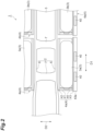
- FIG. 2 is an enlarged plan view of the vehicle body lower structure 10 around the hydrogen tanks 3. Note that, in FIG. 2 , the electric devices mounted on the frame 2 are omitted.
- Each of the plurality of hydrogen tanks 3 stores hydrogen gas for power generation.
- the hydrogen tank 3 has a substantially cylindrical shape extending in an axial direction, and is disposed under the floor of a cargo bed of the vehicle 1 in a state where the axial direction is directed in the front-rear direction D1 of the vehicle 1.
- the plurality of hydrogen tanks 3 includes a pair of hydrogen tanks 3a and a pair of hydrogen tanks 3b.
- the pair of hydrogen tanks 3a is disposed outside the pair of side rails 6 so as to face each other in the vehicle width direction D2.
- the pair of hydrogen tanks 3b is disposed behind the pair of hydrogen tanks 3a and outside the pair of side rails 6 so as to face each other in the vehicle width direction D2.
- the pair of hydrogen tanks 3a and 3b is mounted on the frame 2 between the front axle 11 and the rear axle 12.
- the hydrogen tanks 3a and 3b will be collectively referred to as a hydrogen tank 3 unless it is particularly necessary to distinguish them.
- Pipes for supplying hydrogen stored in a fuel cell stack 21 described later are connected to the plurality of hydrogen tanks 3.
- the plurality of protection members 4 are disposed outside the pair of side rails 6 in the vehicle width direction D2, and protect the plurality of hydrogen tanks 3 from external impact.
- the plurality of protection members 4 include a pair of protection members 4a that respectively protect the pair of hydrogen tanks 3a, and a pair of protection members 4b that respectively protect the pair of hydrogen tanks 3b.
- the pair of protection members 4b is disposed behind the pair of protection members 4a.
- the protection members 4a and 4b will be collectively referred to as the protection member 4 unless it is particularly necessary to distinguish them.
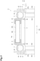
- FIG. 3 is a schematic cross-sectional view taken along line III-III of FIG. 1 .
- the plurality of protection members 4 include a support portion 41, an inner erecting portion 42, an outer erecting portion 43, and a coupling portion 44.
- the support portion 41 supports each of the hydrogen tanks 3.
- the inner erecting portion 42 is erected from the support portion 41 and disposed inside the hydrogen tank 3 in the vehicle width direction D2.
- the inner erecting portions 42 are fastened to outer surfaces of the pair of side rails 6 by fasteners such as bolts.
- the outer erecting portion 43 is erected from the support portion 41 and disposed outside the hydrogen tank 3 in the vehicle width direction D2. That is, the hydrogen tank 3 is disposed between the inner erecting portion 42 and the outer erecting portion 43.
- the outer erecting portion 43 has a substantially L-shape as viewed in the front-rear direction D1 of the vehicle 1, and a protruding portion 43a protruding outward in the vehicle width direction D2 is formed at a lower end of the outer erecting portion 43.
- the lower end (protruding portion 43a) of the outer erecting portion 43 is disposed below a lower end of each of the pair of side rails 6.
- An upper ends of the outer erecting portion 43 is disposed above an upper end of each of the pair of side rails 6.
- the coupling portion 44 extends in the vehicle width direction D2 outside the hydrogen tank 3 in the axial direction, and couples an upper portion of the inner erecting portion 42 and an upper portion of the outer erecting portion 43.
- the coupling portion 44 is disposed at a position overlapping the hydrogen tank 3 as viewed in the front-rear direction D1, and prevents the hydrogen tank 3 from falling off from the protection member 4.
- the coupling portion 44 has such strength as not to be buckled and deformed when another vehicle collides with the vehicle 1 from a side surface.
- a protection region PA protected from an impact F from the side is formed between the pair of protection members 4.
- an area of the protection region PA when viewed from the front-rear direction D1 is larger than an area of a mounting region MA between the pair of side rails 6.
- the first battery 5 is disposed in the protection region PA in order to protect the first battery 5 from the impact F.
- the vehicle body lower structure 10 further includes a plurality of radiators 40 disposed outside the plurality of protection members 4 in the vehicle width direction D2. As illustrated in FIG. 3 , the plurality of radiators 40 are supported by the outer erecting portion 43 of the protection member 4.
- the plurality of radiators 40 includes a pair of radiators 40a disposed outside the pair of protection members 4a in the vehicle width direction D2 and a pair of radiators 40b disposed outside the pair of protection members 4b in the vehicle width direction D2.
- the plurality of radiators 40 may further include a radiator 40d supported on the front portion of the frame 2.
- the heat of the refrigerant flowing inside the radiators is dissipated to the outside air, and the refrigerant is cooled.
- the plurality of radiators 40 supply the cooled refrigerant to the electric devices via a refrigerant flow path to cool the electric devices.
- the first battery 5 is a secondary battery such as a lithium ion battery.
- the first battery 5 is mounted on the frame 2 between the front axle 11 and the rear axle 12, and is supported by the pair of side rails 6 between the pair of protection members 4b. Details of the first battery 5 will be described later.
- the vehicle body lower structure 10 further includes a fuel cell stack 21, high-voltage devices 22a and 22b, motors 23a and 23b, inverters 24a and 24b, and a second battery (another battery) 25.
- the fuel cell stack 21, the high-voltage devices 22a and 22b, the motors 23a and 23b, the inverters 24a and 24b, and the second battery 25 are electric devices for driving the vehicle 1, and are supported between the pair of side rails 6.
- the fuel cell stack 21 is mounted on a front portion of the frame 2, and is disposed under a floor of the cab of the vehicle 1.
- the fuel cell stack 21 generates electric power for driving by chemically reacting hydrogen stored in the hydrogen tank 3 with oxygen in air.
- the high-voltage devices 22a and 22b, the motors 23a and 23b, the inverters 24a and 24b, and the second battery 25 are disposed at a rear portion of the frame 2 and are disposed under the floor of the cargo bed of the vehicle 1.
- the high-voltage devices 22a and 22b are high-voltage auxiliary devices that operate by electric power from the first battery 5 or the second battery 25.
- the high-voltage device 22a includes, for example, a DC-DC converter.
- the DC-DC converter supplies electric power of the first battery 5 or the second battery 25 to various auxiliary devices mounted on the vehicle 1, for example.
- the high-voltage device 22a is disposed between the pair of protection members 4a among the plurality of protection members 4.
- the high-voltage device 22b includes, for example, a brake register controller.
- the brake register controller controls electric power supplied to a brake register (not illustrated) that converts regenerative power generated by the motors 23a and 23b into thermal energy and consumes the thermal energy.
- the high-voltage device 22b is disposed between the pair of protection members 4b among the pair of protection members 4 behind the high-voltage device 22a. More specifically, as illustrated in FIG. 3 , the high-voltage device 22b is disposed above the first battery 5 between the pair of protection members 4b.
- the high-voltage devices 22a and 22b will be collectively referred to as a high-voltage device 22 unless it is particularly necessary to distinguish them.
- the motors 23a and 23b are mounted on the rear portion of the frame 2 and function as an electric motor and a generator. During power running control, the motors 23a and 23b receive electric power supplied from the first battery 5 and the second battery 25, respectively, and generate power for driving the vehicle 1. On the other hand, at the time of regenerative control, the motors 23a and 23b generate load torques for regenerative power generation to generate power. The regenerative power generated by the motor 23a and the motor 23b is supplied to the first battery 5 and the second battery 25, respectively.
- the motors 23a and 23b will be collectively referred to as the motor 23 unless it is particularly necessary to distinguish them.
- the inverter 24a is electrically connected to the motor 23a and the first battery 5.
- the inverter 24a controls electric power supplied to the motor 23a and the first battery 5.
- the inverter 24a converts DC power of the first battery 5 into AC power and supplies the AC power to the motor 23a.
- the inverter 24a converts regenerative power generated by the motor 23a into DC power to charge the first battery 5.
- the inverter 24b is electrically connected to the motor 23b and the second battery 25.
- the inverter 24b controls electric power supplied to the motor 23b and the second battery 25.
- the inverter 24b converts DC power of the second battery 25 into AC power and supplies the AC power to the motor 23b.
- the inverter 24b converts regenerative power generated by the motor 23b into DC power to charge the second battery 25.
- the inverters 24a and 24b will be collectively referred to as an inverter 24 unless it is particularly necessary to distinguish them.
- the second battery 25 is a secondary battery.
- the second battery 25 is a lithium ion battery.
- the first battery 5 is supported by the pair of side rails 6 between the plurality of protection members 4. The first battery 5 supplies electric power to the motor 23a to drive the motor 23a, and rotates the rear wheel RW attached to the rear axle 12.
- the second battery 25 is disposed behind the rear axles 12 and 13 and supported between the pair of side rails 6.
- the second battery 25 supplies electric power to the motor 23b to drive the motor 23b, and rotates the rear wheel RW attached to the rear axle 13.
- FIG. 4 is an enlarged perspective view illustrating a periphery of the first battery 5. Note that, in FIG. 4 , for convenience of description, the high-voltage device 22b is omitted.
- the first battery 5 is fixed to the frame 2 by a plurality of battery brackets 26.
- the plurality of battery brackets 26 couples the first battery 5 to the pair of side rails 6 and hold the first battery 5 under the side rails 6 in a suspended state.
- a part or the whole of the first battery 5 is disposed below the mounting region MA formed between the pair of side rails 6. That is, at least a part of the first battery 5 is disposed below the lower ends of the pair of side rails 6.
- the high-voltage device 22b is mounted in the mounting region MA between the pair of side rails 6, and the first battery 5 is mounted below the high-voltage device 22b.
- a battery may be disposed in both the mounting region MA and a region below the mounting region MA. In this case, since a mounting space of the battery increases, a larger capacity battery can be mounted on the vehicle 1.
- the first battery 5 is supported between the pair of protection members 4b for protecting the pair of hydrogen tanks 3b. Therefore, when another vehicle collides from the side of the vehicle 1, the first battery 5 is protected from impact by the pair of protection members 4b. Therefore, the first battery 5 can be protected from the external impact F without using a protection member dedicated to the first battery 5. As illustrated in FIG. 3 , the first battery 5 is disposed below the lower ends of the pair of side rails 6, but since the first battery 5 is disposed in the protection region PA between the pair of protection members 4b, the first battery 5 can be protected from the external impact F. Therefore, the space around the pair of side rails 6 can be effectively used.
- the first battery 5, and the fuel cell stack 21 are disposed in front of the rear axle 12, a load on the front axle 11 is larger than a load on the rear axle 12.
- a decrease in traveling performance such as a decrease in the loading amount and a decrease in brake performance may occur.
- the second battery 25 is disposed behind the rear axles 12 and 13, it is possible to improve the balance between the load on the front axle 11 and the load on the rear axle 12.
- the vehicle body lower structure according to various embodiments has been described above, various modifications can be made without being limited to the above-described embodiments and without changing the gist of the disclosure.
- the plurality of hydrogen tanks 3 respectively disposed on the pair of side rails 6 include the pair of hydrogen tanks 3a and the pair of hydrogen tanks 3b, but the vehicle body lower structure 10 may include at least one pair of hydrogen tanks 3.
- the pair of radiators 40b is disposed outside the pair of protection members 4b in the vehicle width direction D2, but one radiator may be provided outside one of the at least pair of protection members 4b in the vehicle width direction D2.
- the entire first battery 5 is disposed below the lower ends of the side rails 6, but at least a part of the first battery 5 may be disposed below the lower ends of the side rails 6.
- an upper end of the first battery 5 may be located between the side rails 6, and the lower end of the first battery 5 may be located below the lower ends of the side rails 6.
- the first battery 5 can be increased in size as compared with a case where the first battery 5 is disposed so as to be accommodated in the mounting region MA.
- the first battery 5 and the second battery 25 are lithium ion batteries, but the types of the first battery 5 and the second battery 25 are not particularly limited.
- the various embodiments described above can be combined as long as no contradiction occurs.
Landscapes
- Engineering & Computer Science (AREA)
- Transportation (AREA)
- Mechanical Engineering (AREA)
- Chemical & Material Sciences (AREA)
- Combustion & Propulsion (AREA)
- Life Sciences & Earth Sciences (AREA)
- Sustainable Development (AREA)
- Sustainable Energy (AREA)
- Power Engineering (AREA)
- Body Structure For Vehicles (AREA)
- Cooling, Air Intake And Gas Exhaust, And Fuel Tank Arrangements In Propulsion Units (AREA)
- Arrangement Or Mounting Of Propulsion Units For Vehicles (AREA)
Abstract
A vehicle body lower structure according to one aspect includes: a pair of side rails disposed apart from each other in a width direction of a vehicle and extending in a front-rear direction of the vehicle; a pair of hydrogen tanks respectively disposed outside the pair of side rails in the width direction; a pair of protection members configured to respectively protect the pair of hydrogen tanks from external impact; and a battery supported by the pair of side rails between the pair of protection members.
Description
- The present disclosure relates to a vehicle body lower structure.
-
Japanese Unexamined Patent Publication No. 2022-25814 - In recent years, since a large number of electric devices have been mounted on a vehicle along with improvement of a function of the vehicle, it is required to effectively use a space around a side rail. However, in
Japanese Unexamined Patent Publication No. 2022-25814 - Therefore, an object of the present disclosure is to provide a vehicle body lower structure capable of protecting a battery from an external impact without using an individual protection member.
- A vehicle body lower structure according to one aspect includes: a pair of side rails disposed apart from each other in a vehicle width direction of a vehicle and extending in a front-rear direction of the vehicle; a pair of hydrogen tanks respectively disposed outside the pair of side rails in the vehicle width direction; a pair of protection members configured to respectively protect the pair of hydrogen tanks from external impact; and a battery supported by the pair of side rails between the pair of protection members.
- In the vehicle body lower structure according to the above aspect, since the battery is supported between the pair of protection members for protecting the pair of hydrogen tanks, the battery can be protected from external impact without using a protection member dedicated to the battery.
- According to various embodiments of the present disclosure, the battery can be protected from external impact without using a separate protection member.
-
-
FIG. 1 is a plan view schematically illustrating a vehicle body lower structure according to an embodiment; -
FIG. 2 is an enlarged plan view of a vehicle body lower structure around a hydrogen tank; -
FIG. 3 is a schematic cross-sectional view taken along line III-III ofFIG. 1 ; and -
FIG. 4 is a perspective view illustrating a periphery of a first battery. - First, an overview of embodiments of the present disclosure will be described.
- (Clause 1) Provided are: a pair of side rails disposed apart from each other in a vehicle width direction of a vehicle and extending in a front-rear direction of the vehicle; a pair of hydrogen tanks respectively disposed outside the pair of side rails in the vehicle width direction; a pair of protection members configured to respectively protect the pair of hydrogen tanks from external impact; and a battery supported by the pair of side rails between the pair of protection members. In this vehicle body lower structure, since the battery is supported between the pair of protection members for protecting the pair of hydrogen tanks, the battery can be protected from external impact without using a protection member dedicated to the battery.
- (Clause 2) The vehicle body lower structure according to
Clause 1 may further includes a front axle attached to a front wheel of the vehicle, a rear axle attached to a rear wheel of the vehicle, and another battery different from the battery, in which the battery may be disposed between the front axle and the rear axle, and the another battery may be disposed behind the rear axle. When the battery is disposed in front of the rear axle, a load on the front axle becomes excessive as compared with a load on the rear axle, and as a result, a decrease in traveling performance such as a decrease in brake performance may be caused. On the other hand, when the another battery is disposed behind the rear axle, the balance between the load on the front axle and the load on the rear axle can be improved. - (Clause 3) In the vehicle body lower structure according to
Clause - (Clause 4) The vehicle body lower structure according to any one of
Clauses 1 to 3 may further include a radiator disposed outside one of the pair of protection members in the vehicle width direction. In this case, since an impact from the side of the vehicle is absorbed by the radiator, the battery can be more reliably protected from the impact. - (Clause 5) In the vehicle body lower structure according to any one of
Clauses 1 to 4, the battery may be a lithium ion battery. This vehicle body lower structure can protect a lithium ion battery that is weak against an impact. - Hereinafter, embodiments of the present disclosure will be described with reference to the drawings. In the description of the drawings, the same elements are denoted by the same reference signs, and redundant description is omitted. The drawings may be partially simplified or exaggerated for easy understanding, and dimensional ratios, angles, and the like are not limited to those described in the drawings.
-
FIG. 1 is a plan view schematically illustrating a vehicle bodylower structure 10 of avehicle 1 according to an embodiment. Thevehicle 1 is a large vehicle such as a truck, a cargo vehicle, or a bus vehicle, and is a fuel cell electric vehicle (FCEV) that generates power by chemically reacting hydrogen and oxygen, and travels by driving a motor with the generated power. Hereinafter, an example in which thevehicle 1 is a truck having a cab and a cargo bed will be described. In the following description, a forward direction and a backward direction of thevehicle 1 are referred to as a front-rear direction D1 of thevehicle 1, and a left-right direction when thevehicle 1 is viewed from the rear is referred to as a vehicle width direction D2. - The
vehicle 1 includes a vehicle bodylower structure 10 that supports a cab and a cargo bed. As illustrated inFIG. 1 , the vehicle bodylower structure 10 includes aframe 2, a plurality ofhydrogen tanks 3, a plurality ofprotection members 4, and afirst battery 5. Theframe 2 includes a pair ofside rails 6 disposed apart from each other in the vehicle width direction D2 of thevehicle 1 and extending in the front-rear direction D1 of thevehicle 1, and a plurality ofcross members 7 extending in the vehicle width direction D2 of thevehicle 1 between the pair ofside rails 6 and coupled to the pair ofside rails 6. Theframe 2 is, for example, a ladder frame. A cab in which a driver's seat of thevehicle 1 is disposed is supported on a front portion of theframe 2. A cargo bed on which a load is mounted is supported on a rear portion of theframe 2. - In one embodiment, the vehicle body
lower structure 10 further includes afront axle 11, arear axle 12 and arear axle 13. Thefront axle 11 is attached to a pair of left and right front wheels FW of thevehicle 1. Therear axle 12 is attached to a pair of left and right rear wheels RW of thevehicle 1. Therear axle 13 is disposed behind therear axle 12 and is attached to the pair of left and right rear wheels RW of thevehicle 1. Therear axle 12 and therear axle 13 are drive shafts driven by amotor 23a and amotor 23b to be described later, respectively. - The plurality of
hydrogen tanks 3 are mounted on theframe 2.FIG. 2 is an enlarged plan view of the vehicle bodylower structure 10 around thehydrogen tanks 3. Note that, inFIG. 2 , the electric devices mounted on theframe 2 are omitted. Each of the plurality ofhydrogen tanks 3 stores hydrogen gas for power generation. Thehydrogen tank 3 has a substantially cylindrical shape extending in an axial direction, and is disposed under the floor of a cargo bed of thevehicle 1 in a state where the axial direction is directed in the front-rear direction D1 of thevehicle 1. - As illustrated in
FIG. 2 , the plurality ofhydrogen tanks 3 includes a pair ofhydrogen tanks 3a and a pair ofhydrogen tanks 3b. The pair ofhydrogen tanks 3a is disposed outside the pair ofside rails 6 so as to face each other in the vehicle width direction D2. The pair ofhydrogen tanks 3b is disposed behind the pair ofhydrogen tanks 3a and outside the pair ofside rails 6 so as to face each other in the vehicle width direction D2. The pair ofhydrogen tanks frame 2 between thefront axle 11 and therear axle 12. In the following description, thehydrogen tanks hydrogen tank 3 unless it is particularly necessary to distinguish them. Pipes for supplying hydrogen stored in afuel cell stack 21 described later are connected to the plurality ofhydrogen tanks 3. - As illustrated in
FIG. 1 , the plurality ofprotection members 4 are disposed outside the pair ofside rails 6 in the vehicle width direction D2, and protect the plurality ofhydrogen tanks 3 from external impact. The plurality ofprotection members 4 include a pair ofprotection members 4a that respectively protect the pair ofhydrogen tanks 3a, and a pair ofprotection members 4b that respectively protect the pair ofhydrogen tanks 3b. The pair ofprotection members 4b is disposed behind the pair ofprotection members 4a. In the following description, theprotection members protection member 4 unless it is particularly necessary to distinguish them. - The plurality of
protection members 4 protect the plurality ofhydrogen tanks 3 from external impact, and function as brackets for fixing the plurality ofhydrogen tanks 3 to the pair of side rails 6. The plurality ofprotection members 4 will be described in detail with reference toFIGS. 2 and3. FIG. 3 is a schematic cross-sectional view taken along line III-III ofFIG. 1 . As illustrated inFIG. 3 , the plurality ofprotection members 4 include asupport portion 41, an inner erectingportion 42, an outer erectingportion 43, and acoupling portion 44. Thesupport portion 41 supports each of thehydrogen tanks 3. The inner erectingportion 42 is erected from thesupport portion 41 and disposed inside thehydrogen tank 3 in the vehicle width direction D2. The inner erectingportions 42 are fastened to outer surfaces of the pair ofside rails 6 by fasteners such as bolts. - The outer erecting
portion 43 is erected from thesupport portion 41 and disposed outside thehydrogen tank 3 in the vehicle width direction D2. That is, thehydrogen tank 3 is disposed between the inner erectingportion 42 and the outer erectingportion 43. The outer erectingportion 43 has a substantially L-shape as viewed in the front-rear direction D1 of thevehicle 1, and a protrudingportion 43a protruding outward in the vehicle width direction D2 is formed at a lower end of the outer erectingportion 43. The lower end (protrudingportion 43a) of the outer erectingportion 43 is disposed below a lower end of each of the pair of side rails 6. An upper ends of the outer erectingportion 43 is disposed above an upper end of each of the pair of side rails 6. - The
coupling portion 44 extends in the vehicle width direction D2 outside thehydrogen tank 3 in the axial direction, and couples an upper portion of the inner erectingportion 42 and an upper portion of the outer erectingportion 43. Thecoupling portion 44 is disposed at a position overlapping thehydrogen tank 3 as viewed in the front-rear direction D1, and prevents thehydrogen tank 3 from falling off from theprotection member 4. Thecoupling portion 44 has such strength as not to be buckled and deformed when another vehicle collides with thevehicle 1 from a side surface. - As described above, since the lower end of the outer erecting
portion 43 protrudes outward in the vehicle width direction D2, when another vehicle collides with thevehicle 1 from the side, an impact F from the outside is applied to the protrudingportion 43a of the outer erectingportion 43 as illustrated inFIG. 3 . The impact F applied to the protrudingportion 43a is transmitted to theside rail 6 through thesupport portion 41 and thecoupling portion 44. That is, the impact F from the outside is received by theprotection member 4, and the impact F is prevented from being directly applied to thehydrogen tank 3. As a result, damage to thehydrogen tank 3 is prevented. - By disposing the pair of
protection members 4 outside the pair ofside rails 6, as illustrated inFIG. 3 , a protection region PA protected from an impact F from the side is formed between the pair ofprotection members 4. As illustrated inFIG. 3 , an area of the protection region PA when viewed from the front-rear direction D1 is larger than an area of a mounting region MA between the pair of side rails 6. As described later, thefirst battery 5 is disposed in the protection region PA in order to protect thefirst battery 5 from the impact F. - In one embodiment, the vehicle body
lower structure 10 further includes a plurality ofradiators 40 disposed outside the plurality ofprotection members 4 in the vehicle width direction D2. As illustrated inFIG. 3 , the plurality ofradiators 40 are supported by the outer erectingportion 43 of theprotection member 4. The plurality ofradiators 40 includes a pair ofradiators 40a disposed outside the pair ofprotection members 4a in the vehicle width direction D2 and a pair ofradiators 40b disposed outside the pair ofprotection members 4b in the vehicle width direction D2. The plurality ofradiators 40 may further include aradiator 40d supported on the front portion of theframe 2. When the outside air passes through the plurality ofradiators 40, the heat of the refrigerant flowing inside the radiators is dissipated to the outside air, and the refrigerant is cooled. The plurality ofradiators 40 supply the cooled refrigerant to the electric devices via a refrigerant flow path to cool the electric devices. - The
first battery 5 is a secondary battery such as a lithium ion battery. Thefirst battery 5 is mounted on theframe 2 between thefront axle 11 and therear axle 12, and is supported by the pair ofside rails 6 between the pair ofprotection members 4b. Details of thefirst battery 5 will be described later. - As illustrated in
FIG. 1 , in one embodiment, the vehicle bodylower structure 10 further includes afuel cell stack 21, high-voltage devices motors inverters fuel cell stack 21, the high-voltage devices motors inverters second battery 25 are electric devices for driving thevehicle 1, and are supported between the pair of side rails 6. - The
fuel cell stack 21 is mounted on a front portion of theframe 2, and is disposed under a floor of the cab of thevehicle 1. Thefuel cell stack 21 generates electric power for driving by chemically reacting hydrogen stored in thehydrogen tank 3 with oxygen in air. The high-voltage devices motors inverters second battery 25 are disposed at a rear portion of theframe 2 and are disposed under the floor of the cargo bed of thevehicle 1. - The high-
voltage devices first battery 5 or thesecond battery 25. The high-voltage device 22a includes, for example, a DC-DC converter. The DC-DC converter supplies electric power of thefirst battery 5 or thesecond battery 25 to various auxiliary devices mounted on thevehicle 1, for example. The high-voltage device 22a is disposed between the pair ofprotection members 4a among the plurality ofprotection members 4. - The high-
voltage device 22b includes, for example, a brake register controller. The brake register controller controls electric power supplied to a brake register (not illustrated) that converts regenerative power generated by themotors voltage device 22b is disposed between the pair ofprotection members 4b among the pair ofprotection members 4 behind the high-voltage device 22a. More specifically, as illustrated inFIG. 3 , the high-voltage device 22b is disposed above thefirst battery 5 between the pair ofprotection members 4b. Hereinafter, the high-voltage devices voltage device 22 unless it is particularly necessary to distinguish them. - The
motors frame 2 and function as an electric motor and a generator. During power running control, themotors first battery 5 and thesecond battery 25, respectively, and generate power for driving thevehicle 1. On the other hand, at the time of regenerative control, themotors motor 23a and themotor 23b is supplied to thefirst battery 5 and thesecond battery 25, respectively. Hereinafter, themotors motor 23 unless it is particularly necessary to distinguish them. - The
inverter 24a is electrically connected to themotor 23a and thefirst battery 5. Theinverter 24a controls electric power supplied to themotor 23a and thefirst battery 5. For example, during the power running control, theinverter 24a converts DC power of thefirst battery 5 into AC power and supplies the AC power to themotor 23a. On the other hand, at the time of the regenerative control, theinverter 24a converts regenerative power generated by themotor 23a into DC power to charge thefirst battery 5. - Similarly, the
inverter 24b is electrically connected to themotor 23b and thesecond battery 25. Theinverter 24b controls electric power supplied to themotor 23b and thesecond battery 25. For example, during the power running control, theinverter 24b converts DC power of thesecond battery 25 into AC power and supplies the AC power to themotor 23b. On the other hand, at the time of the regenerative control, theinverter 24b converts regenerative power generated by themotor 23b into DC power to charge thesecond battery 25. Hereinafter, theinverters inverter 24 unless it is particularly necessary to distinguish them. - The
second battery 25 is a secondary battery. In one embodiment, thesecond battery 25 is a lithium ion battery. As described above, thefirst battery 5 is supported by the pair ofside rails 6 between the plurality ofprotection members 4. Thefirst battery 5 supplies electric power to themotor 23a to drive themotor 23a, and rotates the rear wheel RW attached to therear axle 12. - On the other hand, the
second battery 25 is disposed behind therear axles second battery 25 supplies electric power to themotor 23b to drive themotor 23b, and rotates the rear wheel RW attached to therear axle 13. -
FIG. 4 is an enlarged perspective view illustrating a periphery of thefirst battery 5. Note that, inFIG. 4 , for convenience of description, the high-voltage device 22b is omitted. As illustrated inFIG. 4 , thefirst battery 5 is fixed to theframe 2 by a plurality ofbattery brackets 26. The plurality ofbattery brackets 26 couples thefirst battery 5 to the pair ofside rails 6 and hold thefirst battery 5 under the side rails 6 in a suspended state. As a result, as illustrated inFIG. 3 , a part or the whole of thefirst battery 5 is disposed below the mounting region MA formed between the pair of side rails 6. That is, at least a part of thefirst battery 5 is disposed below the lower ends of the pair of side rails 6. - Note that, in the embodiment illustrated in
FIG. 3 , in the protection region PA, the high-voltage device 22b is mounted in the mounting region MA between the pair ofside rails 6, and thefirst battery 5 is mounted below the high-voltage device 22b. However, in one embodiment, a battery may be disposed in both the mounting region MA and a region below the mounting region MA. In this case, since a mounting space of the battery increases, a larger capacity battery can be mounted on thevehicle 1. - As described above, in the vehicle body
lower structure 10 according to the embodiment, thefirst battery 5 is supported between the pair ofprotection members 4b for protecting the pair ofhydrogen tanks 3b. Therefore, when another vehicle collides from the side of thevehicle 1, thefirst battery 5 is protected from impact by the pair ofprotection members 4b. Therefore, thefirst battery 5 can be protected from the external impact F without using a protection member dedicated to thefirst battery 5. As illustrated inFIG. 3 , thefirst battery 5 is disposed below the lower ends of the pair ofside rails 6, but since thefirst battery 5 is disposed in the protection region PA between the pair ofprotection members 4b, thefirst battery 5 can be protected from the external impact F. Therefore, the space around the pair ofside rails 6 can be effectively used. - Furthermore, in the above embodiment, since heavy objects such as the plurality of
hydrogen tanks 3, thefirst battery 5, and thefuel cell stack 21 are disposed in front of therear axle 12, a load on thefront axle 11 is larger than a load on therear axle 12. When the load on thefront axle 11 becomes excessive, a decrease in traveling performance such as a decrease in the loading amount and a decrease in brake performance may occur. On the other hand, in the above embodiment, since thesecond battery 25 is disposed behind therear axles front axle 11 and the load on therear axle 12. - Although the vehicle body lower structure according to various embodiments has been described above, various modifications can be made without being limited to the above-described embodiments and without changing the gist of the disclosure. In the above embodiment, the plurality of
hydrogen tanks 3 respectively disposed on the pair ofside rails 6 include the pair ofhydrogen tanks 3a and the pair ofhydrogen tanks 3b, but the vehicle bodylower structure 10 may include at least one pair ofhydrogen tanks 3. - In the above embodiment, the pair of
radiators 40b is disposed outside the pair ofprotection members 4b in the vehicle width direction D2, but one radiator may be provided outside one of the at least pair ofprotection members 4b in the vehicle width direction D2. - Furthermore, in the above embodiment, the entire
first battery 5 is disposed below the lower ends of the side rails 6, but at least a part of thefirst battery 5 may be disposed below the lower ends of the side rails 6. For example, an upper end of thefirst battery 5 may be located between the side rails 6, and the lower end of thefirst battery 5 may be located below the lower ends of the side rails 6. In this case, thefirst battery 5 can be increased in size as compared with a case where thefirst battery 5 is disposed so as to be accommodated in the mounting region MA. - In the above embodiment, the
first battery 5 and thesecond battery 25 are lithium ion batteries, but the types of thefirst battery 5 and thesecond battery 25 are not particularly limited. The various embodiments described above can be combined as long as no contradiction occurs. -
- 1
- vehicle
- 3
- hydrogen tank
- 4
- protection member
- 5
- first battery (battery)
- 6
- side rail
- 10
- vehicle body lower structure
- 11
- front axle
- 12, 13
- rear axle
- 25
- second battery (another battery)
- 40
- radiator
- D1
- front-rear direction
- D2
- vehicle width direction (width direction)
- F
- impact
Claims (5)
- A vehicle body lower structure comprising:a pair of side rails disposed apart from each other in a vehicle width direction of a vehicle and extending in a front-rear direction of the vehicle;a pair of hydrogen tanks respectively disposed outside the pair of side rails in the vehicle width direction;a pair of protection members configured to respectively protect the pair of hydrogen tanks from external impact; anda battery supported by the pair of side rails between the pair of protection members.
- The vehicle body lower structure according to claim 1, further comprising:a front axle attached to a front wheel of the vehicle;a rear axle attached to a rear wheel of the vehicle; andanother battery different from the battery,wherein the battery is disposed between the front axle and the rear axle, andthe another battery is disposed behind the rear axle.
- The vehicle body lower structure according to claim 1 or 2, wherein at least a part of the battery is disposed below lower ends of the pair of side rails.
- The vehicle body lower structure according to claim 1 or 2, further comprising a radiator disposed outside one of the pair of protection members in the vehicle width direction.
- The vehicle body lower structure according to claim 1 or 2, wherein the battery is a lithium ion battery.
Applications Claiming Priority (1)
| Application Number | Priority Date | Filing Date | Title |
|---|---|---|---|
| JP2023033800A JP2024125754A (en) | 2023-03-06 | 2023-03-06 | Underbody structure |
Publications (1)
| Publication Number | Publication Date |
|---|---|
| EP4427961A1 true EP4427961A1 (en) | 2024-09-11 |
Family
ID=90362453
Family Applications (1)
| Application Number | Title | Priority Date | Filing Date |
|---|---|---|---|
| EP24161524.4A Pending EP4427961A1 (en) | 2023-03-06 | 2024-03-05 | Vehicle body lower structure |
Country Status (4)
| Country | Link |
|---|---|
| US (1) | US20240300324A1 (en) |
| EP (1) | EP4427961A1 (en) |
| JP (1) | JP2024125754A (en) |
| CN (1) | CN118618480A (en) |
Families Citing this family (3)
| Publication number | Priority date | Publication date | Assignee | Title |
|---|---|---|---|---|
| WO2020215023A1 (en) * | 2019-04-19 | 2020-10-22 | Hexagon Purus North America Holdings Inc. | Electric front end accessory devices assembly |
| CA3161967C (en) | 2019-11-26 | 2025-05-13 | Hexagon Purus North America Holdings Inc. | Electric vehicle power distribution and drive control modules |
| CA3205080A1 (en) | 2020-12-11 | 2022-06-16 | Hexagon Purus North America Holdings Inc. | Trailer hookup breakaway mitigation systems and methods |
Citations (6)
| Publication number | Priority date | Publication date | Assignee | Title |
|---|---|---|---|---|
| US20190263450A1 (en) * | 2018-02-28 | 2019-08-29 | Toyota Jidosha Kabushiki Kaisha | Fuel cell vehicle |
| JP2022025814A (en) | 2020-07-30 | 2022-02-10 | ダイムラー・アクチェンゲゼルシャフト | Support device of vehicular battery pack |
| EP3981628A1 (en) * | 2020-10-06 | 2022-04-13 | Volvo Truck Corporation | Vehicle |
| JP2022165246A (en) * | 2021-04-19 | 2022-10-31 | トヨタ自動車株式会社 | fuel cell vehicle |
| US20220388385A1 (en) * | 2019-11-06 | 2022-12-08 | Daimler Ag | Support Device for Vehicle Battery Pack and Electric Vehicle |
| US20230043582A1 (en) * | 2021-08-09 | 2023-02-09 | Hyundai Motor Company | Structure for Mounting Hydrogen Storage Tanks for Vehicle |
Family Cites Families (4)
| Publication number | Priority date | Publication date | Assignee | Title |
|---|---|---|---|---|
| FR2964913B1 (en) * | 2010-09-17 | 2012-09-21 | Peugeot Citroen Automobiles Sa | PROTECTIVE ASSEMBLY FOR A RECEPTACLE OF AN ELECTRIC ENERGY STORAGE SYSTEM FOR A VEHICLE. |
| JP7272867B2 (en) * | 2019-05-31 | 2023-05-12 | メルセデス・ベンツ グループ アクチェンゲゼルシャフト | frame for electric truck |
| JP2022043434A (en) * | 2020-09-04 | 2022-03-16 | ダイムラー・アクチェンゲゼルシャフト | Support device for vehicle battery pack |
| US11728496B2 (en) * | 2021-03-09 | 2023-08-15 | GM Global Technology Operations LLC | Propulsion battery packs with integrated fuel tank mounting systems |
-
2023
- 2023-03-06 JP JP2023033800A patent/JP2024125754A/en active Pending
-
2024
- 2024-03-05 EP EP24161524.4A patent/EP4427961A1/en active Pending
- 2024-03-05 CN CN202410248435.1A patent/CN118618480A/en active Pending
- 2024-03-05 US US18/595,846 patent/US20240300324A1/en active Pending
Patent Citations (6)
| Publication number | Priority date | Publication date | Assignee | Title |
|---|---|---|---|---|
| US20190263450A1 (en) * | 2018-02-28 | 2019-08-29 | Toyota Jidosha Kabushiki Kaisha | Fuel cell vehicle |
| US20220388385A1 (en) * | 2019-11-06 | 2022-12-08 | Daimler Ag | Support Device for Vehicle Battery Pack and Electric Vehicle |
| JP2022025814A (en) | 2020-07-30 | 2022-02-10 | ダイムラー・アクチェンゲゼルシャフト | Support device of vehicular battery pack |
| EP3981628A1 (en) * | 2020-10-06 | 2022-04-13 | Volvo Truck Corporation | Vehicle |
| JP2022165246A (en) * | 2021-04-19 | 2022-10-31 | トヨタ自動車株式会社 | fuel cell vehicle |
| US20230043582A1 (en) * | 2021-08-09 | 2023-02-09 | Hyundai Motor Company | Structure for Mounting Hydrogen Storage Tanks for Vehicle |
Also Published As
| Publication number | Publication date |
|---|---|
| JP2024125754A (en) | 2024-09-19 |
| US20240300324A1 (en) | 2024-09-12 |
| CN118618480A (en) | 2024-09-10 |
Similar Documents
| Publication | Publication Date | Title |
|---|---|---|
| EP4427961A1 (en) | Vehicle body lower structure | |
| US11008041B2 (en) | Fuel cell vehicle | |
| US10720620B1 (en) | High voltage battery pack mounting systems for providing load path management during impact loading events | |
| EP3805027B1 (en) | Electric vehicle | |
| US10518620B2 (en) | Fuel cell mounting structure | |
| CN114987615B (en) | Frame structure for vehicle | |
| US8540282B2 (en) | Protecting structure for power source apparatus | |
| US10065491B1 (en) | Battery pack connector assembly and connecting method | |
| EP2767427A1 (en) | Structure for mounting electric power storage device | |
| CN114162217B (en) | Electric chassis and automobile | |
| US11884166B2 (en) | Battery pack reinforcement assemblies | |
| US10559795B1 (en) | Chassis brace for protecting traction battery | |
| US20250178458A1 (en) | Vehicle structure reinforcement for protecting a battery pack | |
| US11541943B2 (en) | Electric vehicle having low-voltage component in rear portion of vehicle body | |
| US20240010080A1 (en) | Fuel cell vehicle | |
| US12576731B2 (en) | Fuel cell electric vehicle | |
| EP4427993A2 (en) | Vehicle body lower structure | |
| JP7674160B2 (en) | vehicle | |
| CN223533346U (en) | Vehicle with a vehicle body having a vehicle body support | |
| JP2025025467A (en) | Vehicle chassis frame | |
| WO2024236683A1 (en) | Fuel cell vehicle |
Legal Events
| Date | Code | Title | Description |
|---|---|---|---|
| PUAI | Public reference made under article 153(3) epc to a published international application that has entered the european phase |
Free format text: ORIGINAL CODE: 0009012 |
|
| STAA | Information on the status of an ep patent application or granted ep patent |
Free format text: STATUS: THE APPLICATION HAS BEEN PUBLISHED |
|
| AK | Designated contracting states |
Kind code of ref document: A1 Designated state(s): AL AT BE BG CH CY CZ DE DK EE ES FI FR GB GR HR HU IE IS IT LI LT LU LV MC ME MK MT NL NO PL PT RO RS SE SI SK SM TR |
|
| RAP1 | Party data changed (applicant data changed or rights of an application transferred) |
Owner name: HINO MOTORS, LTD. |
|
| STAA | Information on the status of an ep patent application or granted ep patent |
Free format text: STATUS: REQUEST FOR EXAMINATION WAS MADE |
|
| 17P | Request for examination filed |
Effective date: 20250310 |