EP4427896A1 - Methods for complex geometry mandrel removal of ceramic matrix composite components - Google Patents
Methods for complex geometry mandrel removal of ceramic matrix composite components Download PDFInfo
- Publication number
- EP4427896A1 EP4427896A1 EP24161795.0A EP24161795A EP4427896A1 EP 4427896 A1 EP4427896 A1 EP 4427896A1 EP 24161795 A EP24161795 A EP 24161795A EP 4427896 A1 EP4427896 A1 EP 4427896A1
- Authority
- EP
- European Patent Office
- Prior art keywords
- piece
- mandrel
- airfoil
- hollow core
- pulling
- Prior art date
- Legal status (The legal status is an assumption and is not a legal conclusion. Google has not performed a legal analysis and makes no representation as to the accuracy of the status listed.)
- Pending
Links
Images



Classifications
-
- C—CHEMISTRY; METALLURGY
- C04—CEMENTS; CONCRETE; ARTIFICIAL STONE; CERAMICS; REFRACTORIES
- C04B—LIME, MAGNESIA; SLAG; CEMENTS; COMPOSITIONS THEREOF, e.g. MORTARS, CONCRETE OR LIKE BUILDING MATERIALS; ARTIFICIAL STONE; CERAMICS; REFRACTORIES; TREATMENT OF NATURAL STONE
- C04B35/00—Shaped ceramic products characterised by their composition; Ceramics compositions; Processing powders of inorganic compounds preparatory to the manufacturing of ceramic products
- C04B35/71—Ceramic products containing macroscopic reinforcing agents
- C04B35/78—Ceramic products containing macroscopic reinforcing agents containing non-metallic materials
- C04B35/80—Fibres, filaments, whiskers, platelets, or the like
-
- B—PERFORMING OPERATIONS; TRANSPORTING
- B28—WORKING CEMENT, CLAY, OR STONE
- B28B—SHAPING CLAY OR OTHER CERAMIC COMPOSITIONS; SHAPING SLAG; SHAPING MIXTURES CONTAINING CEMENTITIOUS MATERIAL, e.g. PLASTER
- B28B21/00—Methods or machines specially adapted for the production of tubular articles
- B28B21/42—Methods or machines specially adapted for the production of tubular articles by shaping on or against mandrels or like moulding surfaces
- B28B21/48—Methods or machines specially adapted for the production of tubular articles by shaping on or against mandrels or like moulding surfaces by wrapping, e.g. winding
-
- B—PERFORMING OPERATIONS; TRANSPORTING
- B28—WORKING CEMENT, CLAY, OR STONE
- B28B—SHAPING CLAY OR OTHER CERAMIC COMPOSITIONS; SHAPING SLAG; SHAPING MIXTURES CONTAINING CEMENTITIOUS MATERIAL, e.g. PLASTER
- B28B7/00—Moulds; Cores; Mandrels
- B28B7/28—Cores; Mandrels
- B28B7/30—Cores; Mandrels adjustable, collapsible, or expanding
-
- B—PERFORMING OPERATIONS; TRANSPORTING
- B29—WORKING OF PLASTICS; WORKING OF SUBSTANCES IN A PLASTIC STATE IN GENERAL
- B29C—SHAPING OR JOINING OF PLASTICS; SHAPING OF MATERIAL IN A PLASTIC STATE, NOT OTHERWISE PROVIDED FOR; AFTER-TREATMENT OF THE SHAPED PRODUCTS, e.g. REPAIRING
- B29C33/00—Moulds or cores; Details thereof or accessories therefor
- B29C33/44—Moulds or cores; Details thereof or accessories therefor with means for, or specially constructed to facilitate, the removal of articles, e.g. of undercut articles
- B29C33/48—Moulds or cores; Details thereof or accessories therefor with means for, or specially constructed to facilitate, the removal of articles, e.g. of undercut articles with means for collapsing or disassembling
- B29C33/485—Moulds or cores; Details thereof or accessories therefor with means for, or specially constructed to facilitate, the removal of articles, e.g. of undercut articles with means for collapsing or disassembling cores or mandrels
-
- B—PERFORMING OPERATIONS; TRANSPORTING
- B29—WORKING OF PLASTICS; WORKING OF SUBSTANCES IN A PLASTIC STATE IN GENERAL
- B29D—PRODUCING PARTICULAR ARTICLES FROM PLASTICS OR FROM SUBSTANCES IN A PLASTIC STATE
- B29D99/00—Subject matter not provided for in other groups of this subclass
- B29D99/0025—Producing blades or the like, e.g. blades for turbines, propellers, or wings
- B29D99/0028—Producing blades or the like, e.g. blades for turbines, propellers, or wings hollow blades
-
- C—CHEMISTRY; METALLURGY
- C04—CEMENTS; CONCRETE; ARTIFICIAL STONE; CERAMICS; REFRACTORIES
- C04B—LIME, MAGNESIA; SLAG; CEMENTS; COMPOSITIONS THEREOF, e.g. MORTARS, CONCRETE OR LIKE BUILDING MATERIALS; ARTIFICIAL STONE; CERAMICS; REFRACTORIES; TREATMENT OF NATURAL STONE
- C04B35/00—Shaped ceramic products characterised by their composition; Ceramics compositions; Processing powders of inorganic compounds preparatory to the manufacturing of ceramic products
- C04B35/622—Forming processes; Processing powders of inorganic compounds preparatory to the manufacturing of ceramic products
-
- C—CHEMISTRY; METALLURGY
- C04—CEMENTS; CONCRETE; ARTIFICIAL STONE; CERAMICS; REFRACTORIES
- C04B—LIME, MAGNESIA; SLAG; CEMENTS; COMPOSITIONS THEREOF, e.g. MORTARS, CONCRETE OR LIKE BUILDING MATERIALS; ARTIFICIAL STONE; CERAMICS; REFRACTORIES; TREATMENT OF NATURAL STONE
- C04B41/00—After-treatment of mortars, concrete, artificial stone or ceramics; Treatment of natural stone
- C04B41/45—Coating or impregnating, e.g. injection in masonry, partial coating of green or fired ceramics, organic coating compositions for adhering together two concrete elements
- C04B41/4505—Coating or impregnating, e.g. injection in masonry, partial coating of green or fired ceramics, organic coating compositions for adhering together two concrete elements characterised by the method of application
- C04B41/4529—Coating or impregnating, e.g. injection in masonry, partial coating of green or fired ceramics, organic coating compositions for adhering together two concrete elements characterised by the method of application applied from the gas phase
- C04B41/4531—Coating or impregnating, e.g. injection in masonry, partial coating of green or fired ceramics, organic coating compositions for adhering together two concrete elements characterised by the method of application applied from the gas phase by C.V.D.
-
- F—MECHANICAL ENGINEERING; LIGHTING; HEATING; WEAPONS; BLASTING
- F01—MACHINES OR ENGINES IN GENERAL; ENGINE PLANTS IN GENERAL; STEAM ENGINES
- F01D—NON-POSITIVE DISPLACEMENT MACHINES OR ENGINES, e.g. STEAM TURBINES
- F01D5/00—Blades; Blade-carrying members; Heating, heat-insulating, cooling or antivibration means on the blades or the members
- F01D5/12—Blades
- F01D5/14—Form or construction
- F01D5/18—Hollow blades, i.e. blades with cooling or heating channels or cavities; Heating, heat-insulating or cooling means on blades
-
- F—MECHANICAL ENGINEERING; LIGHTING; HEATING; WEAPONS; BLASTING
- F01—MACHINES OR ENGINES IN GENERAL; ENGINE PLANTS IN GENERAL; STEAM ENGINES
- F01D—NON-POSITIVE DISPLACEMENT MACHINES OR ENGINES, e.g. STEAM TURBINES
- F01D5/00—Blades; Blade-carrying members; Heating, heat-insulating, cooling or antivibration means on the blades or the members
- F01D5/12—Blades
- F01D5/28—Selecting particular materials; Particular measures relating thereto; Measures against erosion or corrosion
- F01D5/282—Selecting composite materials, e.g. blades with reinforcing filaments
-
- F—MECHANICAL ENGINEERING; LIGHTING; HEATING; WEAPONS; BLASTING
- F01—MACHINES OR ENGINES IN GENERAL; ENGINE PLANTS IN GENERAL; STEAM ENGINES
- F01D—NON-POSITIVE DISPLACEMENT MACHINES OR ENGINES, e.g. STEAM TURBINES
- F01D5/00—Blades; Blade-carrying members; Heating, heat-insulating, cooling or antivibration means on the blades or the members
- F01D5/12—Blades
- F01D5/28—Selecting particular materials; Particular measures relating thereto; Measures against erosion or corrosion
- F01D5/284—Selection of ceramic materials
-
- C—CHEMISTRY; METALLURGY
- C04—CEMENTS; CONCRETE; ARTIFICIAL STONE; CERAMICS; REFRACTORIES
- C04B—LIME, MAGNESIA; SLAG; CEMENTS; COMPOSITIONS THEREOF, e.g. MORTARS, CONCRETE OR LIKE BUILDING MATERIALS; ARTIFICIAL STONE; CERAMICS; REFRACTORIES; TREATMENT OF NATURAL STONE
- C04B2235/00—Aspects relating to ceramic starting mixtures or sintered ceramic products
- C04B2235/60—Aspects relating to the preparation, properties or mechanical treatment of green bodies or pre-forms
- C04B2235/602—Making the green bodies or pre-forms by moulding
- C04B2235/6028—Shaping around a core which is removed later
-
- C—CHEMISTRY; METALLURGY
- C04—CEMENTS; CONCRETE; ARTIFICIAL STONE; CERAMICS; REFRACTORIES
- C04B—LIME, MAGNESIA; SLAG; CEMENTS; COMPOSITIONS THEREOF, e.g. MORTARS, CONCRETE OR LIKE BUILDING MATERIALS; ARTIFICIAL STONE; CERAMICS; REFRACTORIES; TREATMENT OF NATURAL STONE
- C04B2235/00—Aspects relating to ceramic starting mixtures or sintered ceramic products
- C04B2235/60—Aspects relating to the preparation, properties or mechanical treatment of green bodies or pre-forms
- C04B2235/614—Gas infiltration of green bodies or pre-forms
Definitions
- the present invention relates to chemical vapor infiltration (CVI), and more particularly to improved tooling for CVI.
- Ceramic matrix composite (CMC) parts are widely fabricated by densifying preforms made from woven fabrics or oriented/braided fiber tows.
- CVI is a commonly used densification technique practiced in industry.
- specially designed tooling can be used to hold the preform during the initial densification cycle(s). Until the preform is adequately rigidized, the tooling must remain in contact with the preform to maintain integrity of the desired shape.
- the tooling which forms the internal surfaces must remain inside the part until it is partially or fully rigidized.
- an issue may arise when attempting to extract the tooling after the component has been rigidized if the geometry is highly complex, the tooling is utilized as a partially enclosed core to shape/form the preform (i.e., a mandrel), or substantial surface deviations exist.
- the preform i.e., a mandrel
- means for releasing preforms from tooling without damaging the preforms are desirable.
- a mandrel suitable for supporting an airfoil preform includes a first piece extending along a longitudinal axis of the mandrel, and a second piece in physical contact with the first piece at first interface region and extending along the longitudinal axis of the mandrel.
- the first piece is formed from a first material
- the second piece is formed from a second material.
- a mandrel suitable for supporting an airfoil preform includes a first piece formed from a first material, and a second piece formed from a second material and in physical contact with the first piece at an interface region.
- the interface region extends along a transverse axis of the mandrel.
- a method of forming a ceramic matrix composite (CMC) airfoil includes wrapping a ceramic fabric around a mandrel, densifying the ceramic fabric using chemical vapor infiltration (CVI) to form the CMC airfoil, and removing the mandrel from the CMC airfoil by pulling a first piece of the mandrel out from a hollow core of the airfoil, and pulling a second piece of the mandrel out from the hollow core of the airfoil.
- CVI chemical vapor infiltration
- mandrels can be segmented longitudinally and/or transversely, or off-angle segmented to facilitate removal from complexly shaped airfoil preforms.
- the removal of individual mandrel pieces helps minimize the type and/or extent of damage to a preform that can be caused by unitary mandrels.
- FIG. 1 is a simplified cross-sectional view of a portion of gas turbine engine 10, showing vane assembly 12 and rotor assembly 14.
- Vane assembly 12 includes vane 16, inner diameter (ID) platform 18, and outer diameter (OD) platform 20.
- Rotor assembly 14 includes blade 22 and platform 24.
- Rotor assembly 14 is rotatable about engine axis A.
- the components of vane assembly 12 and rotor assembly 14 can be or can include CMCs formed from sheets/plies/cloths of ceramic fibers arranged in one of various two or three-dimensional woven architectures such as plain, harness (e.g., 3, 5, 8, etc.), twill, braid, or non-symmetric, or from non-woven (e.g., unidirectional, chopped, felted, etc.) fibers.
- the fibers can be reinforced with a ceramic matrix.
- the fibers and/or matrix can be formed from silicon carbide (SiC) or silicon nitride (Si 3 N 4 ), to name a few nonlimiting examples.
- SiC silicon carbide
- Si 3 N 4 silicon nitride
- an airfoil-shaped preform can be formed by wrapping multiple plies around a mandrel having the desired airfoil shape.
- FIG. 2 is a simplified perspective view of airfoil preform 26 mounted on mandrel 28, showing pressure side 30 of airfoil preform 26.
- FIG. 3 is a simplified perspective view of airfoil preform 26 mounted on mandrel 28, rotated from FIG. 2 to show leading edge 32.
- Airfoil preform 26 further includes suction side 34 (visible in FIG. 3 ) opposite pressure side 30, trailing edge 36 opposite leading edge 32, and a hollow core (not visible) occupied by mandrel 28.
- Airfoil preform 26 can be formed from fibrous ceramic plies.
- Mandrel 28 can be formed from at least one of graphite, carbon foam (e.g., reticulated vitreous carbon - RVC), a porous ceramic material, molybdenum, or carbon fiber.
- a molybdenum and/or carbon fiber mandrel 28 can further include a polymeric coating in one embodiment. Multiple materials can be incorporated into a single mandrel 28, for example, by forming different pieces from different materials and/or layering all or part of mandrel 28 with different materials. Depending on its material(s), mandrel 28 can be a single use or multi-use mandrel.
- a mandrel 28 formed from carbon foam, carbon fiber, and/or or molybdenum can be more frangible than a mandrel 28 formed from one or more of the other exemplary materials, although traditional removal techniques can sometimes irreversibly damage mandrel 28 despite its material.
- Mandrel 28 can further include perforations (not shown) for allowing reactant vapors to infiltrate airfoil preform 26 during CVI. After airfoil preform 26 is sufficiently rigidized/densified, mandrel 28 can be removed. However, due to the curved geometry of airfoil preform 26 and the final CMC airfoil, it may be difficult to remove a unitary mandrel 28 without damaging the preform and/or mandrel 28. Additionally, airfoil preform 26 can become adhered to mandrel 28 if the preform material "pillows" into mandrel 28 perforations.
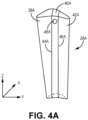
- FIG. 4A is a simplified perspective view of a first embodiment of segmented mandrel 28A.
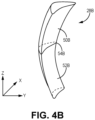
- FIG. 4B is a simplified perspective view of a second embodiment of segmented mandrel 28B.
- Segmented mandrels 28A and 28B can be more easily removed from an airfoil preform (e.g., airfoil preform 26) because they are formed from multiple pieces or sections that can be removed in sequence.
- Segmented mandrel 28A is longitudinally segmented (i.e., with respect to the longitudinal z-axis of mandrel 28A), and includes three distinct pieces 38A, 40A, and 42A.
- Mandrel 28A has an airfoil shape corresponding to airfoil preform 26 such that piece 38A can be a leading edge piece, piece 40A a middle piece, and piece 42A a trailing edge piece.
- Piece 40A is in physical contact with piece 38A at interface 44A, and with piece 42A at interface 46A.
- Each piece 38A, 40A, and 42A can be formed from the same mandrel material, such as one discussed above with respect to mandrel 28, or different materials.
- Mandrel 28A can be single use, multi-use, or include a mixture of single and multi-use pieces. In an alternative embodiment, mandrel 28A can include just two pieces (e.g., just a leading edge piece and trailing edge piece), or more than three pieces (e.g., with multiple middle pieces).
- piece 40A having the least amount of surface area contact with the preform, can be removed first.
- piece 40A can optionally include aperture 48A into which a hook or pin can be inserted and used to pull piece 40A upward along the z-axis. Aperture 48A can extend partially or fully through piece 40A.
- either piece 38A or piece 42A can be urged toward the other (i.e., along the y-axis) by hand or using a tool to free the respective piece from contact with the inner surface of the preform.
- middle piece 40A and interfaces 44A and 46A can alternatively be disposed at an angle (i.e., in the y-z plane) depending, for example, on preform geometry.
- Any of pieces 38A, 40A, and 42A can additionally and/or alternatively be formed with recesses to facilitate removal from the preform, act as conduits for reactant gas infiltration, or both.
- Segmented mandrel 28B is transversely segmented and includes two pieces 50B and 52B in physical contact with one another at interface 54B.
- Interface 54B extends generally transversely (i.e., along the transverse y-axis of mandrel 28B), but can be angled, for example, in the y-z plane.
- Pieces 50B and 52B can be formed from the same mandrel material, such as one discussed above with respect to mandrels 28 and 28A, or different materials.
- Mandrel 28B can be single use, multi-use, or include a mixture of single and multi-use pieces.
- Mandrel 28B may be preferably used with preforms of highly bowed airfoils and/or those with internal hourglass-like curvature, where pulling a mandrel completely through such a preform along the z-axis can be difficult. Accordingly, to remove mandrel 28B from the airfoil, piece 50B can be pulled generally upward (along the z-axis) and piece 52B pulled generally downward. Interface 54B is shown disposed at a longitudinal midpoint of mandrel 28B, but can be longitudinally offset from the midpoint such that piece 50B is longer than piece 52B, or vice versa.
- Mandrel 28B can further be formed such that pieces 50B and 52B taper toward interface 54B such that mandrel 28B is narrowest at interface 54B, whatever its longitudinal position. This may be particularly beneficial for preforms with an internal hourglass-like geometry. Either or both pieces 50B and 52B can include an aperture (not shown) similar to aperture 48A to facilitate removal.
- Mandrels 28A and 28B can include various optional features to prevent unwanted relative movement of the various pieces during layup and/or CVI.
- FIG. 5A is a simplified top view of mandrel 128A showing tab 156A.
- Tab 156A can minimize predominantly longitudinal movement, and some transverse movement of pieces 138A and 140A.
- Tab 156A can be rotatable, as indicated by directional arrows to engage with or disengage with any piece adjacent piece 140A.
- Tab 156A can additionally and/or alternatively be positioned on the bottom of mandrel 128A, on any piece (138A, 140A, or 142A) of mandrel 128A, or in another accessible location to allow for its dis/engagement as needed during processing.
- FIG. 5B is a simplified side view of a portion of mandrel 128B near interface 154B.
- mandrel 128B includes a male-female locking system including internal tabs 156B extending from piece 152B and received by corresponding internal slots 158B on piece 150B.
- the combination of tabs 156B and slots 158B can help minimize predominantly transverse movement, and some longitudinal movement of pieces 150B and 152B.
- Mandrel 128B can additionally and/or alternatively include external tabs (e.g., like tab 156A), or other releasable interlocking means, such as pins, wedges, clamps, etc.
- a mandrel suitable for supporting an airfoil preform includes a first piece extending along a longitudinal axis of the mandrel, and a second piece in physical contact with the first piece at first interface region and extending along the longitudinal axis of the mandrel.
- the first piece is formed from a first material
- the second piece is formed from a second material.
- the mandrel of the preceding paragraph can optionally include, additionally and/or alternatively, any one or more of the following features, configurations and/or additional components:
- the above mandrel can further include a third piece in physical contact with the first piece at a second interface region, and extending along the longitudinal axis of the mandrel.
- the mandrel can have an airfoil shape.
- the first piece can correspond to a middle section of the airfoil shape
- the second piece can correspond to a leading edge section of the airfoil shape
- the third piece can correspond to a trailing edge section of the airfoil shape
- the third piece can be formed from a third material.
- At least one of the first, second, or third materials can include graphite, carbon foam, a porous ceramic, molybdenum, or carbon fiber.
- At least one of the first, second, or third materials can be frangible.
- At least one of the first, second, or third pieces can include a tab engageable with an adjacent piece.
- the first piece can include an aperture
- a mandrel suitable for supporting an airfoil preform includes a first piece formed from a first material, and a second piece formed from a second material and in physical contact with the first piece at an interface region.
- the interface region extends along a transverse axis of the mandrel.
- At least one of the first or second materials can include graphite, carbon foam, a porous ceramic, molybdenum, or carbon fiber.
- the mandrel can be narrowest at the interface region.
- the first piece can include a tab engageable with a slot within the second piece.
- a method of forming a ceramic matrix composite (CMC) airfoil includes wrapping a ceramic fabric around a mandrel, densifying the ceramic fabric using chemical vapor infiltration (CVI) to form the CMC airfoil, and removing the mandrel from the CMC airfoil by pulling a first piece of the mandrel out from a hollow core of the airfoil, and pulling a second piece of the mandrel out from the hollow core of the airfoil.
- CVI chemical vapor infiltration
- the first piece can extend completely through the hollow core of the airfoil and can be pulled out from the hollow core along a longitudinal direction of the mandrel.
- Any of the above methods can further include, prior to pulling the second piece out from the hollow core of the airfoil, urging the second piece away from an inner surface of the airfoil along a transverse axis of the mandrel.
- pulling the first piece out from the hollow core of the airfoil can include inserting a hook or a pin into an aperture in the first piece.
- each of the first piece and the second piece can extend partially into the hollow core of the airfoil.
- pulling the first piece out from the hollow core of the airfoil can include pulling the first piece in a first direction along a longitudinal axis of the mandrel.
- pulling the second piece out from the hollow core of the airfoil can include pulling the second piece in a second direction along a longitudinal axis of the mandrel.
Landscapes
- Engineering & Computer Science (AREA)
- Chemical & Material Sciences (AREA)
- Ceramic Engineering (AREA)
- Mechanical Engineering (AREA)
- Manufacturing & Machinery (AREA)
- Materials Engineering (AREA)
- Organic Chemistry (AREA)
- Structural Engineering (AREA)
- General Engineering & Computer Science (AREA)
- Composite Materials (AREA)
- Inorganic Chemistry (AREA)
- Chemical Kinetics & Catalysis (AREA)
- Turbine Rotor Nozzle Sealing (AREA)
Abstract
Description
- The present invention relates to chemical vapor infiltration (CVI), and more particularly to improved tooling for CVI.
- Ceramic matrix composite (CMC) parts are widely fabricated by densifying preforms made from woven fabrics or oriented/braided fiber tows. CVI is a commonly used densification technique practiced in industry. To keep a preform in a rigid form and maintain proper shape and geometry, specially designed tooling can be used to hold the preform during the initial densification cycle(s). Until the preform is adequately rigidized, the tooling must remain in contact with the preform to maintain integrity of the desired shape. In the case of hollow or cored CMC airfoil construction, the tooling which forms the internal surfaces must remain inside the part until it is partially or fully rigidized. In some instances, an issue may arise when attempting to extract the tooling after the component has been rigidized if the geometry is highly complex, the tooling is utilized as a partially enclosed core to shape/form the preform (i.e., a mandrel), or substantial surface deviations exist. Thus, means for releasing preforms from tooling without damaging the preforms are desirable.
- A mandrel suitable for supporting an airfoil preform includes a first piece extending along a longitudinal axis of the mandrel, and a second piece in physical contact with the first piece at first interface region and extending along the longitudinal axis of the mandrel. The first piece is formed from a first material, and the second piece is formed from a second material.
- A mandrel suitable for supporting an airfoil preform includes a first piece formed from a first material, and a second piece formed from a second material and in physical contact with the first piece at an interface region. The interface region extends along a transverse axis of the mandrel.
- A method of forming a ceramic matrix composite (CMC) airfoil includes wrapping a ceramic fabric around a mandrel, densifying the ceramic fabric using chemical vapor infiltration (CVI) to form the CMC airfoil, and removing the mandrel from the CMC airfoil by pulling a first piece of the mandrel out from a hollow core of the airfoil, and pulling a second piece of the mandrel out from the hollow core of the airfoil.
- Features of embodiments are set forth in the dependent claims.
-
-
FIG. 1 is a simplified cross-sectional view of a portion of a gas turbine engine. -
FIGS 2 and 3 are perspective views of a mandrel-mounted airfoil preform from the pressure side and leading edge, respectively. -
FIGS. 4A and4B are simplified perspective views of first and second embodiments, respectively, of a segmented mandrel. -
FIG. 5A is a simplified top view of a third embodiment of a segmented mandrel. -
FIG. 5B is a simplified side view of a fourth embodiment of a segmented mandrel. - While the above-identified figures set forth one or more embodiments of the present disclosure, other embodiments are also contemplated, as noted in the discussion. In all cases, this disclosure presents the invention by way of representation and not limitation. It should be understood that numerous other modifications and embodiments can be devised by those skilled in the art, which fall within the scope and spirit of the principles of the invention. The figures may not be drawn to scale, and applications and embodiments of the present invention may include features and components not specifically shown in the drawings.
- This disclosure presents various multipiece tooling assemblies for CVI. More specifically, mandrels can be segmented longitudinally and/or transversely, or off-angle segmented to facilitate removal from complexly shaped airfoil preforms. The removal of individual mandrel pieces helps minimize the type and/or extent of damage to a preform that can be caused by unitary mandrels.
-
FIG. 1 is a simplified cross-sectional view of a portion ofgas turbine engine 10, showingvane assembly 12 androtor assembly 14. Vaneassembly 12 includesvane 16, inner diameter (ID)platform 18, and outer diameter (OD)platform 20.Rotor assembly 14 includesblade 22 andplatform 24.Rotor assembly 14 is rotatable about engine axis A. The components ofvane assembly 12 androtor assembly 14 can be or can include CMCs formed from sheets/plies/cloths of ceramic fibers arranged in one of various two or three-dimensional woven architectures such as plain, harness (e.g., 3, 5, 8, etc.), twill, braid, or non-symmetric, or from non-woven (e.g., unidirectional, chopped, felted, etc.) fibers. The fibers can be reinforced with a ceramic matrix. The fibers and/or matrix can be formed from silicon carbide (SiC) or silicon nitride (Si3N4), to name a few nonlimiting examples. To form the airfoil portions (i.e.,vane 16 or blade 22) ofvane assembly 12 andblade assembly 14, an airfoil-shaped preform can be formed by wrapping multiple plies around a mandrel having the desired airfoil shape. -
FIG. 2 is a simplified perspective view ofairfoil preform 26 mounted onmandrel 28, showingpressure side 30 ofairfoil preform 26.FIG. 3 is a simplified perspective view ofairfoil preform 26 mounted onmandrel 28, rotated fromFIG. 2 to show leadingedge 32.Airfoil preform 26 further includes suction side 34 (visible inFIG. 3 )opposite pressure side 30,trailing edge 36 opposite leadingedge 32, and a hollow core (not visible) occupied bymandrel 28.Airfoil preform 26 can be formed from fibrous ceramic plies.Mandrel 28 can be formed from at least one of graphite, carbon foam (e.g., reticulated vitreous carbon - RVC), a porous ceramic material, molybdenum, or carbon fiber. A molybdenum and/orcarbon fiber mandrel 28 can further include a polymeric coating in one embodiment. Multiple materials can be incorporated into asingle mandrel 28, for example, by forming different pieces from different materials and/or layering all or part ofmandrel 28 with different materials. Depending on its material(s),mandrel 28 can be a single use or multi-use mandrel. For example, amandrel 28 formed from carbon foam, carbon fiber, and/or or molybdenum can be more frangible than amandrel 28 formed from one or more of the other exemplary materials, although traditional removal techniques can sometimes irreversibly damagemandrel 28 despite its material. -
Mandrel 28 can further include perforations (not shown) for allowing reactant vapors to infiltrate airfoil preform 26 during CVI. Afterairfoil preform 26 is sufficiently rigidized/densified,mandrel 28 can be removed. However, due to the curved geometry of airfoil preform 26 and the final CMC airfoil, it may be difficult to remove aunitary mandrel 28 without damaging the preform and/ormandrel 28. Additionally,airfoil preform 26 can become adhered tomandrel 28 if the preform material "pillows" intomandrel 28 perforations. -
FIG. 4A is a simplified perspective view of a first embodiment of segmentedmandrel 28A.FIG. 4B is a simplified perspective view of a second embodiment of segmentedmandrel 28B. Segmentedmandrels - Segmented
mandrel 28A is longitudinally segmented (i.e., with respect to the longitudinal z-axis ofmandrel 28A), and includes threedistinct pieces airfoil preform 26 such thatpiece 38A can be a leading edge piece,piece 40A a middle piece, andpiece 42A a trailing edge piece.Piece 40A is in physical contact withpiece 38A atinterface 44A, and withpiece 42A atinterface 46A. Eachpiece mandrel 28, or different materials. Mandrel 28A can be single use, multi-use, or include a mixture of single and multi-use pieces. In an alternative embodiment,mandrel 28A can include just two pieces (e.g., just a leading edge piece and trailing edge piece), or more than three pieces (e.g., with multiple middle pieces). To removemandrel 28A from an airfoil,piece 40A, having the least amount of surface area contact with the preform, can be removed first. To facilitate removal,piece 40A can optionally includeaperture 48A into which a hook or pin can be inserted and used to pullpiece 40A upward along the z-axis.Aperture 48A can extend partially or fully throughpiece 40A. Next, eitherpiece 38A orpiece 42A can be urged toward the other (i.e., along the y-axis) by hand or using a tool to free the respective piece from contact with the inner surface of the preform. Although shown extending primarily along the z-axis,middle piece 40A andinterfaces pieces -
Segmented mandrel 28B is transversely segmented and includes twopieces interface 54B.Interface 54B extends generally transversely (i.e., along the transverse y-axis ofmandrel 28B), but can be angled, for example, in the y-z plane.Pieces mandrels Mandrel 28B can be single use, multi-use, or include a mixture of single and multi-use pieces.Mandrel 28B may be preferably used with preforms of highly bowed airfoils and/or those with internal hourglass-like curvature, where pulling a mandrel completely through such a preform along the z-axis can be difficult. Accordingly, to removemandrel 28B from the airfoil,piece 50B can be pulled generally upward (along the z-axis) andpiece 52B pulled generally downward.Interface 54B is shown disposed at a longitudinal midpoint ofmandrel 28B, but can be longitudinally offset from the midpoint such thatpiece 50B is longer thanpiece 52B, or vice versa.Mandrel 28B can further be formed such thatpieces interface 54B such thatmandrel 28B is narrowest atinterface 54B, whatever its longitudinal position. This may be particularly beneficial for preforms with an internal hourglass-like geometry. Either or bothpieces aperture 48A to facilitate removal. -
Mandrels FIG. 5A is a simplified top view ofmandrel 128Ashowing tab 156A.Tab 156A can minimize predominantly longitudinal movement, and some transverse movement ofpieces Tab 156A can be rotatable, as indicated by directional arrows to engage with or disengage with any pieceadjacent piece 140A.Tab 156A can additionally and/or alternatively be positioned on the bottom ofmandrel 128A, on any piece (138A, 140A, or 142A) ofmandrel 128A, or in another accessible location to allow for its dis/engagement as needed during processing. -
FIG. 5B is a simplified side view of a portion ofmandrel 128B nearinterface 154B. As shown,mandrel 128B includes a male-female locking system includinginternal tabs 156B extending frompiece 152B and received by correspondinginternal slots 158B onpiece 150B. The combination oftabs 156B andslots 158B can help minimize predominantly transverse movement, and some longitudinal movement ofpieces Mandrel 128B can additionally and/or alternatively include external tabs (e.g., liketab 156A), or other releasable interlocking means, such as pins, wedges, clamps, etc. - The following are non-exclusive descriptions of possible embodiments of the present invention.
- A mandrel suitable for supporting an airfoil preform includes a first piece extending along a longitudinal axis of the mandrel, and a second piece in physical contact with the first piece at first interface region and extending along the longitudinal axis of the mandrel. The first piece is formed from a first material, and the second piece is formed from a second material.
- The mandrel of the preceding paragraph can optionally include, additionally and/or alternatively, any one or more of the following features, configurations and/or additional components:
The above mandrel can further include a third piece in physical contact with the first piece at a second interface region, and extending along the longitudinal axis of the mandrel. - In any of the above mandrels, the mandrel can have an airfoil shape.
- In any of the above mandrels, the first piece can correspond to a middle section of the airfoil shape, the second piece can correspond to a leading edge section of the airfoil shape, and the third piece can correspond to a trailing edge section of the airfoil shape.
- In any of the above mandrels, the third piece can be formed from a third material.
- In any of the above mandrels, at least one of the first, second, or third materials can include graphite, carbon foam, a porous ceramic, molybdenum, or carbon fiber.
- In any of the above mandrels, at least one of the first, second, or third materials can be frangible.
- In any of the above mandrels, at least one of the first, second, or third pieces can include a tab engageable with an adjacent piece.
- In any of the above mandrels, the first piece can include an aperture.
- A mandrel suitable for supporting an airfoil preform includes a first piece formed from a first material, and a second piece formed from a second material and in physical contact with the first piece at an interface region. The interface region extends along a transverse axis of the mandrel.
- The mandrel of the preceding paragraph can optionally include, additionally and/or alternatively, any one or more of the following features, configurations and/or additional components:
In the above mandrel, at least one of the first or second materials can include graphite, carbon foam, a porous ceramic, molybdenum, or carbon fiber. - In any of the above mandrels, the mandrel can be narrowest at the interface region.
- In any of the above mandrels, the first piece can include a tab engageable with a slot within the second piece.
- A method of forming a ceramic matrix composite (CMC) airfoil includes wrapping a ceramic fabric around a mandrel, densifying the ceramic fabric using chemical vapor infiltration (CVI) to form the CMC airfoil, and removing the mandrel from the CMC airfoil by pulling a first piece of the mandrel out from a hollow core of the airfoil, and pulling a second piece of the mandrel out from the hollow core of the airfoil.
- The method of the preceding paragraph can optionally include, additionally and/or alternatively, any one or more of the following features, configurations and/or additional components:
In the above method, the first piece can extend completely through the hollow core of the airfoil and can be pulled out from the hollow core along a longitudinal direction of the mandrel. - Any of the above methods can further include, prior to pulling the second piece out from the hollow core of the airfoil, urging the second piece away from an inner surface of the airfoil along a transverse axis of the mandrel.
- In any of the above methods, pulling the first piece out from the hollow core of the airfoil can include inserting a hook or a pin into an aperture in the first piece.
- In any of the above methods, each of the first piece and the second piece can extend partially into the hollow core of the airfoil.
- In any of the above methods, pulling the first piece out from the hollow core of the airfoil can include pulling the first piece in a first direction along a longitudinal axis of the mandrel.
- In any of the above methods, pulling the second piece out from the hollow core of the airfoil can include pulling the second piece in a second direction along a longitudinal axis of the mandrel.
- While the invention has been described with reference to an exemplary embodiment(s), it will be understood by those skilled in the art that various changes may be made and equivalents may be substituted for elements thereof without departing from the scope of the invention. In addition, many modifications may be made to adapt a particular situation or material to the teachings of the invention without departing from the essential scope thereof. Therefore, it is intended that the invention not be limited to the particular embodiment(s) disclosed, but that the invention will include all embodiments falling within the scope of the appended claims.
Claims (15)
- A mandrel (28; 28A; 128A) suitable for supporting an airfoil preform (26), the mandrel (28; 28A; 128A) comprising:a first piece (40A; 140A) extending along a longitudinal axis of the mandrel (28; 28A); anda second piece (38A; 138A) in physical contact with the first piece (40A; 140A) at first interface region (44A), and extending along the longitudinal axis of the mandrel (28; 28A; 128A);wherein the first piece (40A; 140A) is formed from a first material; andwherein the second piece (38A; 138A) is formed from a second material.
- The mandrel of claim 1 and further comprising:
a third piece (42A; 142A) in physical contact with the first piece (40A; 140A) at a second interface region (46A), and extending along the longitudinal axis of the mandrel (28; 28A; 128A). - The mandrel of claim 2, wherein the mandrel (28; 28A; 128A) has an airfoil shape.
- The mandrel of claim 3, wherein the first piece (40A; 140A) corresponds to a middle section of the airfoil shape, the second piece (38A; 138A) corresponds to a leading edge section (32) of the airfoil shape, and the third piece (42A; 142A) corresponds to a trailing edge section (36) of the airfoil shape.
- The mandrel of any of claims 2 to 4, wherein the third piece (42A; 142A) is formed from a third material.
- The mandrel of any preceding claim, wherein at least one of the first, second, or third materials comprises graphite, carbon foam, a porous ceramic, molybdenum, or carbon fiber; and/or wherein at least one of the first, second, or third materials is frangible.
- The mandrel of any preceding claim, wherein at least one of the first, second, or third pieces (40A, 38A, 42A; 140A, 138A, 142A) comprises a tab (156A) engageable with an adjacent piece (38A, 42A, 40A; 138A, 142A, 140A).
- The mandrel of any preceding claim, wherein the first piece (40A; 140A) comprises an aperture (48A).
- A mandrel (28B; 128B) suitable for supporting an airfoil preform (26), the mandrel (28B; 128B) comprising:a first piece (52B; 152B) formed from a first material; anda second piece (50B; 150B) formed from a second material and in physical contact with the first piece (52B; 152B) at an interface region (54B; 154B);wherein the interface region (54B; 154B) extends along a transverse axis of the mandrel (28B; 128B).
- The mandrel of claim 9, wherein at least one of the first or second materials comprises graphite, carbon foam, a porous ceramic, molybdenum, or carbon fiber.
- The mandrel of claim 9 or 10, wherein the mandrel (28B; 128B) is narrowest at the interface region (54B; 154B); and/or wherein the first piece (152B) comprises a tab (156B) engageable with a slot (128B) within the second piece (150B).
- A method of forming a ceramic matrix composite (CMC) airfoil (16; 22), the method comprising:wrapping a ceramic fabric around a mandrel (28; 28A; 28B; 128A; 128B);densifying the ceramic fabric using chemical vapor infiltration (CVI) to form the CMC airfoil (16; 22); andremoving the mandrel (28; 28A; 28B; 128A; 128B) from the CMC airfoil (16; 22) by:pulling a first piece (40A; 140A; 52B; 152B) of the mandrel (28; 28A; 28B; 128A; 128B) out from a hollow core of the airfoil (16; 22); andpulling a second piece (38A; 138A; 50B; 150B) of the mandrel (28; 28A; 28B; 128A; 128B) out from the hollow core of the airfoil (16; 22).
- The method of claim 12, wherein the first piece (40A; 140A) extends completely through the hollow core of the airfoil (16; 22) and is pulled out from the hollow core along a longitudinal direction of the mandrel (28; 28A; 128A), optionally, wherein pulling the first piece (40A; 140A) out from the hollow core of the airfoil (16; 22) comprises inserting a hook or a pin into an aperture (48A) in the first piece (40A; 140A).
- The method of claim 12 or 13 and further comprising:
prior to pulling the second piece (38A; 138A) out from the hollow core of the airfoil (16; 22), urging the second piece (38A; 138A) away from an inner surface of the airfoil (16; 22) along a transverse axis of the mandrel (28; 28A; 128A). - The method of claim 12, wherein each of the first piece (52B; 152B) and the second piece (50B; 150B) extends partially into the hollow core of the airfoil (16; 22), optionally, wherein:pulling the first piece (52B; 152B) out from the hollow core of the airfoil (16; 22) comprises pulling the first piece (52B; 152B) in a first direction along a longitudinal axis of the mandrel (28B; 128B); and/orpulling the second piece (50B; 150B) out from the hollow core of the airfoil (16; 22) comprises pulling the second piece (50B; 150B) in a second direction along a longitudinal axis of the mandrel (28B; 128B).
Applications Claiming Priority (1)
| Application Number | Priority Date | Filing Date | Title |
|---|---|---|---|
| US18/118,443 US12528228B2 (en) | 2023-03-07 | 2023-03-07 | Methods for complex geometry mandrel removal of ceramic matrix composite components |
Publications (1)
| Publication Number | Publication Date |
|---|---|
| EP4427896A1 true EP4427896A1 (en) | 2024-09-11 |
Family
ID=90362224
Family Applications (1)
| Application Number | Title | Priority Date | Filing Date |
|---|---|---|---|
| EP24161795.0A Pending EP4427896A1 (en) | 2023-03-07 | 2024-03-06 | Methods for complex geometry mandrel removal of ceramic matrix composite components |
Country Status (2)
| Country | Link |
|---|---|
| US (1) | US12528228B2 (en) |
| EP (1) | EP4427896A1 (en) |
Cited By (2)
| Publication number | Priority date | Publication date | Assignee | Title |
|---|---|---|---|---|
| EP4520499A1 (en) * | 2023-09-11 | 2025-03-12 | RTX Corporation | Flared mandrel and method of forming a vane preform using it |
| EP4729269A1 (en) * | 2024-10-15 | 2026-04-22 | RTX Corporation | Plastic encased carbonaceous foam mandrel and method |
Families Citing this family (2)
| Publication number | Priority date | Publication date | Assignee | Title |
|---|---|---|---|---|
| US12552085B2 (en) | 2023-10-20 | 2026-02-17 | Rtx Corporation | Z-channeling into a preform via needle perforation in a stand-alone tool |
| US12473236B2 (en) * | 2023-10-20 | 2025-11-18 | Rtx Corporation | Internal tooling configuration for the creation of z-channels in woven ceramic matrix composite preforms |
Citations (5)
| Publication number | Priority date | Publication date | Assignee | Title |
|---|---|---|---|---|
| US20110274553A1 (en) * | 2010-04-16 | 2011-11-10 | Henrik Stiesdal | Method for Manufacturing a Wind Turbine Rotor Blade and Wind Turbine Rotor Blade |
| US20150369052A1 (en) * | 2012-04-09 | 2015-12-24 | Peter de DIEGO | Thin-Walled Reinforcement Lattice Structure for Hollow CMC Buckets |
| US20180236694A1 (en) * | 2015-10-29 | 2018-08-23 | Bayerische Motoren Werke Aktiengesellschaft | Core System, Use of the Core System in the Production of a Fiber Composite Component and Method for Producing a Fiber Composite Component |
| US20210381384A1 (en) * | 2020-06-03 | 2021-12-09 | Raytheon Technologies Corporation | Multi-piece mandrel for cmc components |
| EP4325026A1 (en) * | 2022-08-15 | 2024-02-21 | RTX Corporation | Airfoil leading edge venturi cooling passage |
Family Cites Families (2)
| Publication number | Priority date | Publication date | Assignee | Title |
|---|---|---|---|---|
| GB201513236D0 (en) | 2015-07-28 | 2015-09-09 | Rolls Royce Plc | A nozzle guide vane passage |
| US11400624B2 (en) | 2018-09-24 | 2022-08-02 | Raytheon Technologies Corporation | Constant cross section mandrel for CMC components |
-
2023
- 2023-03-07 US US18/118,443 patent/US12528228B2/en active Active
-
2024
- 2024-03-06 EP EP24161795.0A patent/EP4427896A1/en active Pending
Patent Citations (5)
| Publication number | Priority date | Publication date | Assignee | Title |
|---|---|---|---|---|
| US20110274553A1 (en) * | 2010-04-16 | 2011-11-10 | Henrik Stiesdal | Method for Manufacturing a Wind Turbine Rotor Blade and Wind Turbine Rotor Blade |
| US20150369052A1 (en) * | 2012-04-09 | 2015-12-24 | Peter de DIEGO | Thin-Walled Reinforcement Lattice Structure for Hollow CMC Buckets |
| US20180236694A1 (en) * | 2015-10-29 | 2018-08-23 | Bayerische Motoren Werke Aktiengesellschaft | Core System, Use of the Core System in the Production of a Fiber Composite Component and Method for Producing a Fiber Composite Component |
| US20210381384A1 (en) * | 2020-06-03 | 2021-12-09 | Raytheon Technologies Corporation | Multi-piece mandrel for cmc components |
| EP4325026A1 (en) * | 2022-08-15 | 2024-02-21 | RTX Corporation | Airfoil leading edge venturi cooling passage |
Cited By (2)
| Publication number | Priority date | Publication date | Assignee | Title |
|---|---|---|---|---|
| EP4520499A1 (en) * | 2023-09-11 | 2025-03-12 | RTX Corporation | Flared mandrel and method of forming a vane preform using it |
| EP4729269A1 (en) * | 2024-10-15 | 2026-04-22 | RTX Corporation | Plastic encased carbonaceous foam mandrel and method |
Also Published As
| Publication number | Publication date |
|---|---|
| US12528228B2 (en) | 2026-01-20 |
| US20240300142A1 (en) | 2024-09-12 |
Similar Documents
| Publication | Publication Date | Title |
|---|---|---|
| EP4427896A1 (en) | Methods for complex geometry mandrel removal of ceramic matrix composite components | |
| RU2523308C2 (en) | Production of turbomachine blade from composite | |
| CN102782256B (en) | Turbine engine blade made of composite material and method of manufacturing same | |
| US9080454B2 (en) | Composite material turbine engine vane, and method for manufacturing same | |
| CN102971135B (en) | There is the turbine set blade of complementary non-symmetrical geometries | |
| JP6302479B2 (en) | Device with engineering surface features and corresponding method for reducing wear and friction in CMC-metal attachments | |
| EP4098417B1 (en) | Method of forming a ceramic matrix composite component having an internal cooling circuit | |
| EP3181814A1 (en) | Fiber reinforced airfoil | |
| EP4086055A1 (en) | Method for creating cooling holes in a cmc laminate | |
| EP4541535A1 (en) | Z-channeling into a preform via needle perforation in a stand-alone tool | |
| EP3760604B1 (en) | Method of forming cooling channels in a ceramic matrix composite component | |
| EP4357114A1 (en) | Floating tooling assembly for chemical vapor infiltration | |
| EP4047183B1 (en) | Bifurcating layup for airfoil rib, methods of manufacture thereof and articles comprising the same | |
| EP4177052B1 (en) | 3d woven space filler | |
| EP4345185A1 (en) | Minimization of chemical vapor infiltration tooling hole length through counterbores | |
| EP4541536A1 (en) | Tooling configuration for the creation of z-channels in woven ceramic matrix composite (cmc) preforms | |
| EP4527581A1 (en) | Deformable mandrel made of auxetic material and method of fabricating a ceramic matrix composite component using the same | |
| US12479775B2 (en) | Chemical vapor infiltration tooling for optimizing infiltration in ceramic matrix composites | |
| EP4470992A1 (en) | Prefabricated noodle | |
| EP4345186A1 (en) | Minimization of chemical vapor infiltration tooling holes length through windows |
Legal Events
| Date | Code | Title | Description |
|---|---|---|---|
| PUAI | Public reference made under article 153(3) epc to a published international application that has entered the european phase |
Free format text: ORIGINAL CODE: 0009012 |
|
| STAA | Information on the status of an ep patent application or granted ep patent |
Free format text: STATUS: THE APPLICATION HAS BEEN PUBLISHED |
|
| AK | Designated contracting states |
Kind code of ref document: A1 Designated state(s): AL AT BE BG CH CY CZ DE DK EE ES FI FR GB GR HR HU IE IS IT LI LT LU LV MC ME MK MT NL NO PL PT RO RS SE SI SK SM TR |
|
| STAA | Information on the status of an ep patent application or granted ep patent |
Free format text: STATUS: REQUEST FOR EXAMINATION WAS MADE |
|
| 17P | Request for examination filed |
Effective date: 20250303 |
|
| STAA | Information on the status of an ep patent application or granted ep patent |
Free format text: STATUS: EXAMINATION IS IN PROGRESS |
|
| 17Q | First examination report despatched |
Effective date: 20250502 |