EP4427849A1 - System for coating substrates in a fluidized bed zone - Google Patents
System for coating substrates in a fluidized bed zone Download PDFInfo
- Publication number
- EP4427849A1 EP4427849A1 EP23160444.8A EP23160444A EP4427849A1 EP 4427849 A1 EP4427849 A1 EP 4427849A1 EP 23160444 A EP23160444 A EP 23160444A EP 4427849 A1 EP4427849 A1 EP 4427849A1
- Authority
- EP
- European Patent Office
- Prior art keywords
- fluidized bed
- units
- coupled
- bed zone
- unit
- Prior art date
- Legal status (The legal status is an assumption and is not a legal conclusion. Google has not performed a legal analysis and makes no representation as to the accuracy of the status listed.)
- Pending
Links
Images




Classifications
-
- B—PERFORMING OPERATIONS; TRANSPORTING
- B05—SPRAYING OR ATOMISING IN GENERAL; APPLYING FLUENT MATERIALS TO SURFACES, IN GENERAL
- B05C—APPARATUS FOR APPLYING FLUENT MATERIALS TO SURFACES, IN GENERAL
- B05C19/00—Apparatus specially adapted for applying particulate materials to surfaces
- B05C19/02—Apparatus specially adapted for applying particulate materials to surfaces using fluidised-bed techniques
Definitions
- the present invention relates to a system for coating a substrate, such as a busbar, with fluidized powder in a fluidized bed zone.
- the system facilitates increasing the fluidized bed zone in a flexible manner.
- the busbars include conductors for transmission and insulating materials. Commonly used conductors for busbars include copper bars, aluminum bars and copper-aluminum composite bars.
- the insulating materials can include for instance polymers.
- busbars are insulated by coating in a fluidized bed.
- busbars are subjected to increased temperatures. Then the busbars are discharged into a fluidized bed. Subsequently, the busbars are exposed to curing.
- a powder with solid particles is mixed with a fluidizing gas, such as air, under increased pressure. This is performed by guiding air through holes of a membrane into the fluidized bed.
- the mixing forms a fluidized condition of the powder, having typical fluid properties, such as the ability to free flow under gravity, or to be pumped using fluid technologies. This facilitates coating.
- the fluidizing gas should be evenly distributed, and the fluidized conditions must be maintained throughout the process. Furthermore, the fluidized bed should facilitate coating busbars or any kind of substrates, having various sizes. Moreover, since the powders employed for coating are usually expensive, unnecessary usage of this resource should be avoided. Further still, the fluidized bed must be able to cope with various kinds of powders.
- An aspect of the invention relates to a system for coating a substrate, such as a busbar, with fluidized powder, the system comprising: one or more units, each unit comprising: a housing; a fluidized bed zone arranged within the housing for maintaining powder in a substantially fluidized condition; and a membrane assembly for at least partially sealing the fluidized bed zone within the housing, wherein the membrane assembly is arranged at the bottom of the fluidized bed zone as seen during ordinary use of the system; wherein each unit is configured to be coupled with another unit such that the fluidized bed zones of the coupled units form a coherent fluidized bed zone.
- the present disclosure provides a system for coating a substrate, which has the advantage that the size (e.g. the volume) and the shape of the fluidized bed zone can be varied in a flexible and convenient manner.
- Each unit may be coupled with another unit in various configurations to form a coherent fluidized bed zone.
- Such coherent fluidized bed zone may be suited to fit to the space requirements dictated by substrates, such as a busbar, which are to be coated. This facilitates that substantially the same unit may be used for coating various substrates. This reduces costs as the unit can be manufactured in greater number. Further, an oversized unit for coating rather large substrates as done in the prior art is not required.
- the amount of powder for rather small substrates can be reduced, since coupling a small number of units is sufficient for coating such substrates.
- the space occupied by such a system can also be reduced.
- the membrane assembly for at least partially sealing the fluidized bed zone has the advantage that, for instance, an outer rim of the membrane assembly is substantially sealed. This improves maintaining the fluidized condition.
- the outer rim may comprise a sealing gasket. Remaining portions of the membrane assembly facilitate that air, such as compressed air, can be guided through it to aid in providing a substantially fluidized condition.
- the membrane assembly may comprise a metal cover and a membrane and said sealing gasket. The metal cover may support the membrane. The metal cover may be surrounded by said sealing gasket, forming the outer rim of the membrane assembly.
- the bottom of the fluidized bed zone is understood such that, if the system stands on the ground (i.e., which is the case during ordinary use of the system), the bottom of the fluidized bed zone may be in proximity to the ground.
- the bottom of the fluidized bed zone may be lower than its top seen along the vertical direction.
- To be coupled with another unit means that the units are substantially fixed with one another.
- the units can be removed in an uncoupled state easily. This is beneficial to facilitate diverse sizes of a coherent fluidized bed zone in a fast and flexible manner.
- the fluidized bed zone comprises powder in a substantially fluidized condition.
- the fluidized condition may be understood similarly to liquefaction, wherein a powder material is converted from a substantially solid state to a substantially (dynamic) fluid state.
- a fluidized condition occurs when a fluid, e.g. a liquid or gas, is guided into the powder material. Said fluid may be guided through the membrane for instance.
- the coherent fluidized bed zone is understood such that it is recognizable as one integral zone so as to functionally operate as one fluidized bed zone. It may not be separated, e.g. by elements or parts.
- the membrane assembly is configured to be coupled with the membrane assembly of another unit in a substantially sealing manner.
- the membrane assemblies can form a substantially sealing bottom of the coherent fluidized bed zone.
- the membrane assemblies are configured to be coupled in a flexible manner. This supports to vary the size of the coherent fluidized bed zone easily.
- the housing comprises guide members for removably receiving the membrane assembly within the housing.
- the membrane assembly can be easily received and removed within the housing. Further, the membrane assembly can be easily exchanged with another one. This is beneficial in case powders of several types are employed. Typically, one membrane assembly is suited for one type of powder. The types may differ in color and/or material.
- each unit is configured to be coupled with another unit such that a part of a frame of the housing is substantially abutting a part of a frame of the housing of another unit, preferably in an at least partially sealing manner.
- the frame may comprise several parts.
- the housing may have a cuboid shape and one part of the frame may be associated with one side of the cuboid shape (along the height of the unit).
- coupling can be established in a flexible manner, e.g. on any desired part (e.g. side of the cuboid shape) of the frame.
- abutting parts may be fixed with fixing means to one other. This improves the structural integrity of the system and ensures that the formed coherent fluidized bed zone is maintained safely and reliably.
- the membrane assembly is configured to engage with an I-beam of the system for coupling with the membrane assembly of another unit, such that the membrane assemblies are each engaging with the I-beam on opposing sides.
- the I-beam is understood as comprising horizontal elements, e.g. flanges, and a vertical element, e.g. a web in its profile.
- the term I-beam can comprise various materials.
- the I-beam can comprise metal materials.
- the membrane assembly has the shape of a substantially flat plate, wherein the thickness of the plate is smaller than the depth of the I-beam, such that the membrane assembly can be received at least partially in a recess of the I-beam.
- the part enclosed by the flanges of the I-beam and the web on one side of the I-beam's profile may be understood as the recess.
- the I-beam may have two recesses in its profile.
- the depth of the I-beam may be the distance between the two flanges.
- the membrane assembly of the unit has at least one, preferably at least two, more preferably at least three, most preferably four side surfaces, arranged substantially perpendicularly to the bottom of the fluidized bed zone, wherein each side surface is configured to engage with the I-beam.
- each side surface can be received at least partially in the recess of the I-beam.
- the membrane assembly can engage with the I-beam and/or the guide members easily.
- the membrane assembly can be arranged in any configuration/orientation, for instance it can be rotated, whilst still being able to engage with the I-beam.
- the I-beam may have a similar composition as the guide members. For instance, it may have similar dimensions and/or material. Thereby, it may resemble the guide members. Further, since the membrane assembly may comprise a gasket at its rim (e.g. a rubber gasket), providing for an I-beam may improve coupling, as it provides for some rigidity.
- a gasket at its rim e.g. a rubber gasket
- each side surface is configured to be received at least partially in the guide members, wherein, preferably, each side surface can be received at least partially in a recess of the guide members.
- the membrane assembly can be arranged in any configuration/orientation (e.g. rotated about an axis along its thickness), whilst still being received in a recess of the guide members.
- the recess of the guide members may resemble the recess of the I-beam.
- the housing has a cuboid shape with four sides extending along a height of the unit, wherein each unit is configured to be coupled with another unit on at least two, preferably at least three, most preferably on four sides of the housing.
- the cuboid shape has the advantage that the units can be placed more easily in proximity to one another. This saves space.
- the cross-section of the housing thus has a rectangular shape. Coupling on different sides of the cuboid shape of the housing increases flexibility of the system. The system can thus be adapted to a certain shape requirement of the substrate to be coated in the coherent fluidized bed zone.
- the height of the unit is measured along the extension in the vertical direction, as seen during ordinary use of the system (e.g. if the system stands on the ground).
- the fluidized bed zone has a substantially rectangular cross-section as seen from the top during ordinary use of the system, wherein the length of each side of the rectangular cross-section is in the range of 50 mm to 1,000 mm, preferably 100 mm to 950 mm, more preferably 150 mm to 900 mm, more preferably 200 mm to 850 mm, more preferably 250 mm to 750 mm, more preferably 300 mm to 700 mm, more preferably 350 mm to 650 mm, more preferably 400 mm to 600 mm, most preferably 450 mm to 550 mm.
- the length is not too small. This ensures that the number of units needed to be coupled in order to form a coherent fluidized bed zone for coating a substrate is reduced. This is beneficial for relatively large substrates to be coated.
- the length is not too large. This ensures that an amount of powder needed for coating can be reduced as the size of the coherent fluidized is not too large. This is beneficial for small substrates to be coated.
- the housing of the unit has a height extending along a vertical direction as seen during ordinary use of the system in the range of 1,000 mm to 3,000 mm, preferably 1,500 mm to 2,500 mm, most preferably 1,800 mm to 2,100 mm.
- each unit is configured to be coupled with at least two, preferably at least three, most preferably four other units.
- each unit can be coupled to a plurality of other units at the same time. This increases flexibility.
- the fluidized bed zones of the coupled units form a coherent fluidized bed zone.
- the area of the cross-section of the coherent fluidized bed zone corresponds to the sum of the areas of the cross-sections of the fluidized bed zone of each unit.
- the housing when the units are coupled, at least two, preferably at least three, most preferably four parts of a frame the housing are each abutting a part of a frame of the housing of another unit, preferably in an at least partially sealing manner, wherein the parts of the unit are substantially perpendicularly to one another.
- the fluidized bed zone comprises powder in a substantially fluidized condition, wherein, optionally, the powder comprises insulation material, such as thermoplastic and/or thermosetting resins, preferably the powder comprises epoxy resin and/or polyamide, such as polyamide 12, most preferably the powder substantially consists of epoxy resin and/or polyamide, such as polyamide 12.
- insulation material such as thermoplastic and/or thermosetting resins
- the powder comprises epoxy resin and/or polyamide, such as polyamide 12, most preferably the powder substantially consists of epoxy resin and/or polyamide, such as polyamide 12.
- the powder substantially consists of epoxy resin and/or polyamide, such as polyamide 12, the powder may still encompass further material(s), which have, however, a rather small content. For instance, impurities could be present in the powder. This tolerance is expressed by the term substantially.
- Epoxy powder coatings are advantageous for substrates comprising copper and/or aluminum.
- Busbars may be made of copper and/or aluminum and conduct electricity, for instance between two or more electric circuits. In this manner, epoxy powder coatings can improve properties of said busbars.
- the system comprises at least two, preferably at least three, more preferably at least four, more preferably at least five, most preferably at least six units, wherein the units are coupled with one another such that the fluidized bed zones of the coupled units form a coherent fluidized bed zone.
- the units are coupled in series, such that the cross-section of the coherent fluidized bed zone, as seen from the top during ordinary use of the system, has the shape of a rectangle.
- the units are coupled in series, such that the cross-section of the coherent fluidized bed zone, as seen from the top during ordinary use of the system, has the shape of a rectangle.
- the units are coupled in series, such that the cross-section of the coherent fluidized bed zone, as seen from the top during ordinary use of the system, has the shape of a rectangle, or the units are coupled such that the cross-section of the coherent fluidized bed zone, as seen from the top during ordinary use of the system, has the shape of a cross.
- the system comprises six units
- four units are coupled in series and two units are coupled perpendicularly to the direction of the four units coupled in series.
- One unit may then be coupled to four other units at the same time.
- the remaining units may be coupled with two or one other units at the same time.
- Fig. 1 shows an arrangement of systems 1 (left), 1' (right) for coating a substrate according to two embodiments of the present disclosure.
- the fluidized bed zone 20 may be used for coating busbars. Further applications, particularly further coating applications, i.e. coating of further parts, are certainly possible.
- the fluidizing bed zone 20 may be employed for loosening and aerating powders in order to coat the busbars. Fluidization of the powder may reduce the interactions in between particles of the powder, which are further apart one another.
- the system 1 on the left-hand side comprises one unit 5 .
- the unit 5 comprises a housing 10, a fluidized bed zone 20 arranged within the housing 10 for maintaining powder in a substantially fluidized condition, and a membrane assembly 30 (as best seen in Fig. 2 ) for at least partially sealing the fluidized bed zone 20 within the housing 10.
- the membrane assembly 30 is arranged at the bottom of the fluidized bed zone as seen during ordinary use of the system 1 (as best seen in Fig. 2 ).
- the unit 5 is configured to be coupled with another unit 5', 5", 5′′′ such that the fluidized bed zones 20, 20', 20", 20′′′ of the coupled units 5, 5', 5", 5′′′ form a coherent fluidized bed zone.
- Fig. 1 which comprises four units 5', 5", 5′′′.
- the coherent fluidized bed zone is represented in Fig. 1 by the combination of the volumes of the fluidized bed zones 20, 20', 20", 20′′′.
- the fluidized powder is in direct communication within the combination of the fluidized bed zones 20, 20', 20", 20"'.
- each unit 5 has a cuboid shape with four sides extending along the height H (indicated on the right-hand side of Fig. 1 ) of the unit 5. As can be seen in system 1', each unit 5 is coupled with another unit 5 on at least one or two sides of the housing 10 of each unit.
- the region above the fluidized bed zone 20 in the housing 10 may be free of such powder during ordinary use of the system 1 and may be used as a manipulation space. For instance, handling of substrates to be coated with the powder could be performed therein.
- the holes 15 may be used for as an extraction connection. For instance, the holes 15 may be used to adjust excess powder from the atmosphere.
- Fig. 2 shows an arrangement of the system according to the first embodiment of Fig. 1 in greater detail.
- Fig. 2 generally represents a unit 5 according to an embodiment of the present disclosure.
- the housing 10 comprises guide members 11, 12 for removably receiving the membrane assembly 30 within the housing 10.
- the membrane assembly 30 is depicted two times (left-hand side and right-hand side) in Fig. 2 to highlight details thereof.
- the membrane assembly 30 on the right-hand side is shown in an explosion view.
- the membrane assembly 30 comprises a membrane 31, a metal grid 32, and a sealing gasket 33.
- the metal grid 32 can support the membrane 31 and is surrounded by the sealing gasket 33, forming the outer rim of the membrane assembly 30.
- the membrane assembly 30 facilitates that air, such as compressed air, can be guided through it to provide a substantially fluidized condition of the powder in the fluidized bed zone 20.
- the membrane assembly 30 has the shape of a substantially flat plate. It can be seen that the thickness of the plate (as seen in the direction T indicated in Fig. 2 ) is smaller than the depth of the I-beam 40 (as also indicated in Fig. 3 ), such that the membrane assembly 30 can be received at least partially in a recess of the I-beam 40.
- the fluidized bed zone 20 has a substantially rectangular cross-section as seen from the top during ordinary use of the system 1 .
- the length L1, L2 of each side of the rectangular cross-section is in the range of 50 mm to 1,000 mm, most preferably between 450 mm to 550 mm.
- the housing 10 of the unit 5 has a height H extending along a vertical direction as seen during ordinary use of the system 1 in the range of 1,000 mm to 3,000 mm, preferably 1,500 mm to 2,500 mm, most preferably 1,800 mm to 2,100 mm.
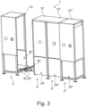
- Fig. 3 shows an arrangement of the system 1' according to the second embodiment of Fig. 1 in greater detail.
- Fig. 3 shows the coupling of the membrane assemblies 30, 30' in greater detail.
- the membrane assembly 30, 30' of each unit 5,5' is configured to be coupled with the membrane assembly 30', 30 of another unit 5', 5 in a substantially sealing manner.
- each unit 5,5' is configured to be coupled with another unit 5', 5 such that a part of a frame of the housing 10 is substantially abutting a part of a frame of the housing 10' of another unit 5'. This is done in an at least partially sealing manner.
- the membrane assembly 30 is configured to engage with an I-beam 40 for coupling with the membrane assembly 30' of the other unit 5'. Thereby, the membrane assemblies 30, 30' are each engaging with the I-beam 40 on opposing sides of the I-beam 40.
- the membrane assembly 30 of the unit 5 has four side surfaces, arranged substantially perpendicularly to the bottom of the fluidized bed zone 20. Each side surface can engage with the I-beam 40. For instance, the membrane assembly 30 can be rotated about an axis along its thickness T by an angle of a plurality of about 90° whilst still being able to engage with the I-beam 40.
- Each side surface of the membrane assembly 30 is configured to be received at least partially in the guide members 11, 12.
- the system 1' as depicted herein comprises four units 5, 5', 5", 5′′′ coupled in series, such that the cross-section of the coherent fluidized bed zone, as seen from the top during ordinary use of the system 1', has the shape of a rectangle.
- Fig. 4 shows an arrangement of a system 1" according to a third embodiment of the present disclosure in different perspectives.
- Each unit of the five units 5, 5', 5", 5′′′, 5 ⁇ is configured to be coupled with at least two, preferably at least three, most preferably four other units.
- unit 5 ⁇ is coupled with four other units.
- the fluidized bed zones of the coupled units form a coherent fluidized bed zone.
- the area of the cross-section of the coherent fluidized bed zone, as seen from the top during ordinary use of the system 1" corresponds to the sum of the areas of the cross-sections of the fluidized bed zone of each unit.
- a frame the housing 10 ⁇ of unit 5 ⁇ are each abutting a part of a frame of the housing of the respective other four units. This is done in an at least partially sealing manner.
- the parts of the frame of unit 5 ⁇ are substantially perpendicularly to one another.
- the system 1" as depicted herein comprises five units 5, 5', 5", 5′′′, 5 ⁇ , the units are coupled such that the cross-section of the coherent fluidized bed zone, as seen from the top during ordinary use of the system 1", has the shape of a cross.
- Fig. 5 shows an arrangement of a system 1′′′ according to a fourth embodiment of the present disclosure in different perspectives.
- the system 1′′′ as depicted herein comprises six units 5, 5', 5", 5′′′, 5 ⁇ , 5′′′ ⁇ .
- Four units 5', 5′′′, 5 ⁇ , 5′′′ ⁇ are coupled in series and two units 5, 5" are coupled perpendicularly to the direction of the four units 5', 5′′′, 5 ⁇ , 5′′′ ⁇ coupled in series.
- the fluidized bed zone 20 may comprise powder in a substantially fluidized condition.
- the powder may comprise insulation material, such as thermoplastic and/or thermosetting resins.
- the powder comprises epoxy resin and/or polyamide, such as polyamide 12, most preferably the powder substantially consists of epoxy resin and/or polyamide, such as polyamide 12.
Landscapes
- Devices And Processes Conducted In The Presence Of Fluids And Solid Particles (AREA)
Abstract
Description
- The present invention relates to a system for coating a substrate, such as a busbar, with fluidized powder in a fluidized bed zone. The system facilitates increasing the fluidized bed zone in a flexible manner.
- Increasing globalization and industrialization goes hand in hand with a growing demand of equipment for power transmission, such as busbars or the like. Further, as the automotive sector faces a shift towards electric vehicles, such growing demand of equipment for power transmission becomes particularly relevant for vehicles.
- The busbars include conductors for transmission and insulating materials. Commonly used conductors for busbars include copper bars, aluminum bars and copper-aluminum composite bars. The insulating materials can include for instance polymers. Typically, busbars are insulated by coating in a fluidized bed.
- In such a coating process, the busbars are subjected to increased temperatures. Then the busbars are discharged into a fluidized bed. Subsequently, the busbars are exposed to curing.
- In the fluidized bed, a powder with solid particles is mixed with a fluidizing gas, such as air, under increased pressure. This is performed by guiding air through holes of a membrane into the fluidized bed. The mixing forms a fluidized condition of the powder, having typical fluid properties, such as the ability to free flow under gravity, or to be pumped using fluid technologies. This facilitates coating.
- In the fluidized bed, the fluidizing gas should be evenly distributed, and the fluidized conditions must be maintained throughout the process. Furthermore, the fluidized bed should facilitate coating busbars or any kind of substrates, having various sizes. Moreover, since the powders employed for coating are usually expensive, unnecessary usage of this resource should be avoided. Further still, the fluidized bed must be able to cope with various kinds of powders.
- In the prior art, attempts have been made to meet these requirements. For instance, known fluidized beds are bathtubs or open tanks with fixed dimensions. This creates difficulties in coating substrates of varied sizes. In particular, independent on the size of the substrates, the same amount of powder must be procured in order to fill the bathtubs or open tanks, which increases costs. Further, for larger substrates, larger bathtubs or tanks must be provided, which increases capital costs and makes it more difficult to ensure an even distribution of pressure along the entire length of the membrane. This, in turn, adversely affects coating.
- Hence, the prior art solutions are not flexible, but cumbersome in handling substrates and cost intensive.
- It is thus an object of the present invention to overcome some or all of the deficiencies of the prior art. In particular, it is an object of the invention to provide for an improved system for coating substrates in a fluidized bed. Thus, costs should be reduced, and flexibility should be increased.
- The above-mentioned objects are at least partially achieved by the subject-matter of the independent claims. Preferred embodiments are subject of the dependent claims, and the skilled person finds hints for other suitable aspects of the present invention through the overall disclosure of the present application.
- An aspect of the invention relates to a system for coating a substrate, such as a busbar, with fluidized powder, the system comprising: one or more units, each unit comprising: a housing; a fluidized bed zone arranged within the housing for maintaining powder in a substantially fluidized condition; and a membrane assembly for at least partially sealing the fluidized bed zone within the housing, wherein the membrane assembly is arranged at the bottom of the fluidized bed zone as seen during ordinary use of the system; wherein each unit is configured to be coupled with another unit such that the fluidized bed zones of the coupled units form a coherent fluidized bed zone.
- In this manner, the present disclosure provides a system for coating a substrate, which has the advantage that the size (e.g. the volume) and the shape of the fluidized bed zone can be varied in a flexible and convenient manner. Each unit may be coupled with another unit in various configurations to form a coherent fluidized bed zone. Such coherent fluidized bed zone may be suited to fit to the space requirements dictated by substrates, such as a busbar, which are to be coated. This facilitates that substantially the same unit may be used for coating various substrates. This reduces costs as the unit can be manufactured in greater number. Further, an oversized unit for coating rather large substrates as done in the prior art is not required.
- Furthermore, the amount of powder for rather small substrates can be reduced, since coupling a small number of units is sufficient for coating such substrates. The space occupied by such a system can also be reduced.
- The membrane assembly for at least partially sealing the fluidized bed zone has the advantage that, for instance, an outer rim of the membrane assembly is substantially sealed. This improves maintaining the fluidized condition. In one example, the outer rim may comprise a sealing gasket. Remaining portions of the membrane assembly facilitate that air, such as compressed air, can be guided through it to aid in providing a substantially fluidized condition. The membrane assembly may comprise a metal cover and a membrane and said sealing gasket. The metal cover may support the membrane. The metal cover may be surrounded by said sealing gasket, forming the outer rim of the membrane assembly.
- The bottom of the fluidized bed zone is understood such that, if the system stands on the ground (i.e., which is the case during ordinary use of the system), the bottom of the fluidized bed zone may be in proximity to the ground. The bottom of the fluidized bed zone may be lower than its top seen along the vertical direction.
- To be coupled with another unit means that the units are substantially fixed with one another. The units can be removed in an uncoupled state easily. This is beneficial to facilitate diverse sizes of a coherent fluidized bed zone in a fast and flexible manner.
- In one example, the fluidized bed zone comprises powder in a substantially fluidized condition.
- The fluidized condition may be understood similarly to liquefaction, wherein a powder material is converted from a substantially solid state to a substantially (dynamic) fluid state. Such a fluidized condition occurs when a fluid, e.g. a liquid or gas, is guided into the powder material. Said fluid may be guided through the membrane for instance.
- The coherent fluidized bed zone is understood such that it is recognizable as one integral zone so as to functionally operate as one fluidized bed zone. It may not be separated, e.g. by elements or parts.
- In a preferred embodiment of the system, the membrane assembly is configured to be coupled with the membrane assembly of another unit in a substantially sealing manner.
- This has the advantage that the membrane assemblies can form a substantially sealing bottom of the coherent fluidized bed zone. The membrane assemblies are configured to be coupled in a flexible manner. This supports to vary the size of the coherent fluidized bed zone easily.
- Preferably, in the system, the housing comprises guide members for removably receiving the membrane assembly within the housing.
- This has the advantage that the membrane assembly can be easily received and removed within the housing. Further, the membrane assembly can be easily exchanged with another one. This is beneficial in case powders of several types are employed. Typically, one membrane assembly is suited for one type of powder. The types may differ in color and/or material.
- In a preferred embodiment of the system, each unit is configured to be coupled with another unit such that a part of a frame of the housing is substantially abutting a part of a frame of the housing of another unit, preferably in an at least partially sealing manner.
- This improves coupling of each unit with another unit. Abutting has the advantage that the parts are contacting each other, such that the interior of the coupled units may be substantially sealed. The frame may comprise several parts. In one example, the housing may have a cuboid shape and one part of the frame may be associated with one side of the cuboid shape (along the height of the unit). Thereby, coupling can be established in a flexible manner, e.g. on any desired part (e.g. side of the cuboid shape) of the frame.
- It is understood that the abutting parts may be fixed with fixing means to one other. This improves the structural integrity of the system and ensures that the formed coherent fluidized bed zone is maintained safely and reliably.
- In a preferred embodiment of the system, the membrane assembly is configured to engage with an I-beam of the system for coupling with the membrane assembly of another unit, such that the membrane assemblies are each engaging with the I-beam on opposing sides.
- This has the advantage that coupling is improved and simplified. Engaging with the I-beam on opposing sides aids in ensuring a substantially sealing coupling. Further, it promotes that coupling may be easily reverted. It is understood that the system comprises the I-beam. Usually, for coupling one unit with another unit, one I-beam is employed.
- The I-beam is understood as comprising horizontal elements, e.g. flanges, and a vertical element, e.g. a web in its profile. The term I-beam can comprise various materials. For instance, the I-beam can comprise metal materials.
- Preferably, in the system, the membrane assembly has the shape of a substantially flat plate, wherein the thickness of the plate is smaller than the depth of the I-beam, such that the membrane assembly can be received at least partially in a recess of the I-beam.
- This has the advantage that a coherent fluidized bed zone of various sizes can be easily formed. In particular, the membrane assembly easily fits to the recess of the I-beam, which aids coupling.
- The part enclosed by the flanges of the I-beam and the web on one side of the I-beam's profile may be understood as the recess. The I-beam may have two recesses in its profile. The depth of the I-beam may be the distance between the two flanges.
- In a preferred embodiment of the system, the membrane assembly of the unit has at least one, preferably at least two, more preferably at least three, most preferably four side surfaces, arranged substantially perpendicularly to the bottom of the fluidized bed zone, wherein each side surface is configured to engage with the I-beam. Optionally, each side surface can be received at least partially in the recess of the I-beam.
- In this manner, the membrane assembly can engage with the I-beam and/or the guide members easily. In particular, the membrane assembly can be arranged in any configuration/orientation, for instance it can be rotated, whilst still being able to engage with the I-beam.
- In one example, the I-beam may have a similar composition as the guide members. For instance, it may have similar dimensions and/or material. Thereby, it may resemble the guide members. Further, since the membrane assembly may comprise a gasket at its rim (e.g. a rubber gasket), providing for an I-beam may improve coupling, as it provides for some rigidity.
- Preferably, in the system, each side surface is configured to be received at least partially in the guide members, wherein, preferably, each side surface can be received at least partially in a recess of the guide members.
- This further facilitates a simplified coupling. For coupling, the membrane assembly can be arranged in any configuration/orientation (e.g. rotated about an axis along its thickness), whilst still being received in a recess of the guide members. The recess of the guide members may resemble the recess of the I-beam.
- In a preferred embodiment of the system, the housing has a cuboid shape with four sides extending along a height of the unit, wherein each unit is configured to be coupled with another unit on at least two, preferably at least three, most preferably on four sides of the housing.
- The cuboid shape has the advantage that the units can be placed more easily in proximity to one another. This saves space. The cross-section of the housing thus has a rectangular shape. Coupling on different sides of the cuboid shape of the housing increases flexibility of the system. The system can thus be adapted to a certain shape requirement of the substrate to be coated in the coherent fluidized bed zone.
- It is understood that the height of the unit is measured along the extension in the vertical direction, as seen during ordinary use of the system (e.g. if the system stands on the ground).
- Preferably, in the system, the fluidized bed zone has a substantially rectangular cross-section as seen from the top during ordinary use of the system, wherein the length of each side of the rectangular cross-section is in the range of 50 mm to 1,000 mm, preferably 100 mm to 950 mm, more preferably 150 mm to 900 mm, more preferably 200 mm to 850 mm, more preferably 250 mm to 750 mm, more preferably 300 mm to 700 mm, more preferably 350 mm to 650 mm, more preferably 400 mm to 600 mm, most preferably 450 mm to 550 mm.
- In this manner, the inventors found an optimum balance of the length of each side of the rectangular cross section.
- The length is not too small. This ensures that the number of units needed to be coupled in order to form a coherent fluidized bed zone for coating a substrate is reduced. This is beneficial for relatively large substrates to be coated.
- Likewise, the length is not too large. This ensures that an amount of powder needed for coating can be reduced as the size of the coherent fluidized is not too large. This is beneficial for small substrates to be coated.
- Preferably, the housing of the unit has a height extending along a vertical direction as seen during ordinary use of the system in the range of 1,000 mm to 3,000 mm, preferably 1,500 mm to 2,500 mm, most preferably 1,800 mm to 2,100 mm.
- In this manner, the inventors found an optimum balance of the height extending along a vertical direction of the housing. Similar advantages as explained with respect to the length of each side of the rectangular cross-section apply in here.
- In a preferred embodiment of the system, each unit is configured to be coupled with at least two, preferably at least three, most preferably four other units.
- Thereby, the system provides the advantage that each unit can be coupled to a plurality of other units at the same time. This increases flexibility.
- Preferably, when the units are coupled, the fluidized bed zones of the coupled units form a coherent fluidized bed zone.
- This has the advantage that the size of the coherent fluidized bed zone formed by the coupled units can be varied (increased/decreased) in a flexible manner. Further, this also has the advantage that the shape of the coherent fluidized bed zone can be varied. Thereby, several different shapes of the coherent fluidized bed zone can be established by the same number of units. The different shapes can be targeted to specific space/shape requirements of substrates.
- Preferably, the area of the cross-section of the coherent fluidized bed zone, as seen from the top during ordinary use of the system, corresponds to the sum of the areas of the cross-sections of the fluidized bed zone of each unit.
- This allows to increase/decrease the size of the coherent fluidized bed zone in a predictive manner.
- In a preferred embodiment of the system, when the units are coupled, at least two, preferably at least three, most preferably four parts of a frame the housing are each abutting a part of a frame of the housing of another unit, preferably in an at least partially sealing manner, wherein the parts of the unit are substantially perpendicularly to one another.
- This has the advantage that, if a unit is coupled with two, three or four other units, the respective parts of the frames are abutting each other. This provides for a tight and space saving system.
- Preferably, in the system, the fluidized bed zone comprises powder in a substantially fluidized condition, wherein, optionally, the powder comprises insulation material, such as thermoplastic and/or thermosetting resins, preferably the powder comprises epoxy resin and/or polyamide, such as
polyamide 12, most preferably the powder substantially consists of epoxy resin and/or polyamide, such aspolyamide 12. - This facilitates coating substrates with an insulation material. The respective material may be procured easily. If the powder substantially consists of epoxy resin and/or polyamide, such as
polyamide 12, the powder may still encompass further material(s), which have, however, a rather small content. For instance, impurities could be present in the powder. This tolerance is expressed by the term substantially. - Epoxy powder coatings are advantageous for substrates comprising copper and/or aluminum. Busbars may be made of copper and/or aluminum and conduct electricity, for instance between two or more electric circuits. In this manner, epoxy powder coatings can improve properties of said busbars.
- In a preferred embodiment of the system, the system comprises at least two, preferably at least three, more preferably at least four, more preferably at least five, most preferably at least six units, wherein the units are coupled with one another such that the fluidized bed zones of the coupled units form a coherent fluidized bed zone.
- Preferably, when the system comprises three units, the units are coupled in series, such that the cross-section of the coherent fluidized bed zone, as seen from the top during ordinary use of the system, has the shape of a rectangle.
- Preferably, when the system comprises four units, the units are coupled in series, such that the cross-section of the coherent fluidized bed zone, as seen from the top during ordinary use of the system, has the shape of a rectangle.
- Preferably, when the system comprises five units, the units are coupled in series, such that the cross-section of the coherent fluidized bed zone, as seen from the top during ordinary use of the system, has the shape of a rectangle, or the units are coupled such that the cross-section of the coherent fluidized bed zone, as seen from the top during ordinary use of the system, has the shape of a cross.
- Preferably, when the system comprises six units, four units are coupled in series and two units are coupled perpendicularly to the direction of the four units coupled in series. One unit may then be coupled to four other units at the same time. The remaining units may be coupled with two or one other units at the same time.
- This has the advantage that various configurations can be established by coupling the units of the system accordingly. Hence, the size and shape of the coherent fluidized bed zone can be adjusted in a simplified manner.
- In the following, preferred embodiments of the disclosure are disclosed by reference to the accompanying figures.
- Fig. 1:
- illustrates an arrangement of systems according to two embodiments of the present disclosure.
- Fig. 2:
- illustrates an arrangement of the system according to the first embodiment of
Fig. 1 in greater detail. - Fig. 3:
- illustrates an arrangement of the system according to the second embodiment of
Fig. 1 in greater detail. - Fig. 4:
- illustrates an arrangement of a system according to a third embodiment of the present disclosure in different perspectives.
- Fig. 5:
- illustrates an arrangement of a system according to a fourth embodiment of the present disclosure in different perspectives.
- In the subsequent passages, the invention is described with reference to the accompanying figures in more detail. It is noted that further embodiments are certainly possible, and the below explanations are provided by way of example only, without limitation. Throughout the present figures and specification, the same reference numerals refer to the same elements. The figures may not be to scale, and the relative size, proportions, and depiction of elements in the figures may be exaggerated for clarity, illustration, and convenience.
- Substantially all features described with reference to a unit and/or a system of one embodiment also apply to units and/or systems of another embodiment, unless stated to the contrary.
-
Fig. 1 shows an arrangement of systems 1 (left), 1' (right) for coating a substrate according to two embodiments of the present disclosure. - The
fluidized bed zone 20 may be used for coating busbars. Further applications, particularly further coating applications, i.e. coating of further parts, are certainly possible. The fluidizingbed zone 20 may be employed for loosening and aerating powders in order to coat the busbars. Fluidization of the powder may reduce the interactions in between particles of the powder, which are further apart one another. - The
system 1 on the left-hand side comprises oneunit 5. Theunit 5 comprises ahousing 10, afluidized bed zone 20 arranged within thehousing 10 for maintaining powder in a substantially fluidized condition, and a membrane assembly 30 (as best seen inFig. 2 ) for at least partially sealing thefluidized bed zone 20 within thehousing 10. Themembrane assembly 30 is arranged at the bottom of the fluidized bed zone as seen during ordinary use of the system 1 (as best seen inFig. 2 ). - The
unit 5 is configured to be coupled with anotherunit 5', 5", 5‴ such that thefluidized bed zones units Fig. 1 , which comprises fourunits 5', 5", 5‴. The coherent fluidized bed zone is represented inFig. 1 by the combination of the volumes of thefluidized bed zones fluidized bed zones - The
housing 10 of eachunit 5 has a cuboid shape with four sides extending along the height H (indicated on the right-hand side ofFig. 1 ) of theunit 5. As can be seen in system 1', eachunit 5 is coupled with anotherunit 5 on at least one or two sides of thehousing 10 of each unit. - The
fluidized bed zone 20 is arranged in a lower region of theunit 5 and has a height of about 400 mm to 600 mm. Thisfluidized bed zone 20 is usually filled up to about at least 50%, 60%, 70%, or 80% of its height during ordinary use of thesystem 1 with fluidized powder. It may not be filled up to 100%, because the powder level rises during aeration (e.g. blowing of air through the membrane assembly). Thus, the amount of powder should be selected so that it does not come out of thefluidized bed zone 20 during aeration. - The region above the
fluidized bed zone 20 in thehousing 10 may be free of such powder during ordinary use of thesystem 1 and may be used as a manipulation space. For instance, handling of substrates to be coated with the powder could be performed therein. Theholes 15 may be used for as an extraction connection. For instance, theholes 15 may be used to adjust excess powder from the atmosphere. -
Fig. 2 shows an arrangement of the system according to the first embodiment ofFig. 1 in greater detail.Fig. 2 generally represents aunit 5 according to an embodiment of the present disclosure. - The
housing 10 comprisesguide members membrane assembly 30 within thehousing 10. - The
membrane assembly 30 is depicted two times (left-hand side and right-hand side) inFig. 2 to highlight details thereof. Themembrane assembly 30 on the right-hand side is shown in an explosion view. - The
membrane assembly 30 comprises amembrane 31, ametal grid 32, and a sealinggasket 33. Themetal grid 32 can support themembrane 31 and is surrounded by the sealinggasket 33, forming the outer rim of themembrane assembly 30. Themembrane assembly 30 facilitates that air, such as compressed air, can be guided through it to provide a substantially fluidized condition of the powder in thefluidized bed zone 20. - The
membrane assembly 30 has the shape of a substantially flat plate. It can be seen that the thickness of the plate (as seen in the direction T indicated inFig. 2 ) is smaller than the depth of the I-beam 40 (as also indicated inFig. 3 ), such that themembrane assembly 30 can be received at least partially in a recess of the I-beam 40. - The
unit 5 also comprises acover panel 13 and acover gasket 14. This aids in sealing thefluidized bed zone 20 at least partially. - The
fluidized bed zone 20 has a substantially rectangular cross-section as seen from the top during ordinary use of thesystem 1. The length L1, L2 of each side of the rectangular cross-section is in the range of 50 mm to 1,000 mm, most preferably between 450 mm to 550 mm. - The
housing 10 of theunit 5 has a height H extending along a vertical direction as seen during ordinary use of thesystem 1 in the range of 1,000 mm to 3,000 mm, preferably 1,500 mm to 2,500 mm, most preferably 1,800 mm to 2,100 mm. -
Fig. 3 shows an arrangement of the system 1' according to the second embodiment ofFig. 1 in greater detail. In particular,Fig. 3 shows the coupling of themembrane assemblies 30, 30' in greater detail. - The
membrane assembly 30, 30' of eachunit 5,5' is configured to be coupled with themembrane assembly 30', 30 of anotherunit 5', 5 in a substantially sealing manner. - It can be seen that each
unit 5,5' is configured to be coupled with anotherunit 5', 5 such that a part of a frame of thehousing 10 is substantially abutting a part of a frame of thehousing 10' of another unit 5'. This is done in an at least partially sealing manner. - The
membrane assembly 30 is configured to engage with an I-beam 40 for coupling with the membrane assembly 30' of the other unit 5'. Thereby, themembrane assemblies 30, 30' are each engaging with the I-beam 40 on opposing sides of the I-beam 40. - The
membrane assembly 30 of theunit 5 has four side surfaces, arranged substantially perpendicularly to the bottom of thefluidized bed zone 20. Each side surface can engage with the I-beam 40. For instance, themembrane assembly 30 can be rotated about an axis along its thickness T by an angle of a plurality of about 90° whilst still being able to engage with the I-beam 40. - Each side surface of the
membrane assembly 30 is configured to be received at least partially in theguide members - The system 1' as depicted herein comprises four
units -
Fig. 4 shows an arrangement of asystem 1" according to a third embodiment of the present disclosure in different perspectives. - Each unit of the five
units system 1", corresponds to the sum of the areas of the cross-sections of the fluidized bed zone of each unit. - As also seen in
Fig. 4 , four parts of a frame the housing 10ʺʺ of unit 5ʺʺ are each abutting a part of a frame of the housing of the respective other four units. This is done in an at least partially sealing manner. The parts of the frame of unit 5ʺʺ are substantially perpendicularly to one another. - The
system 1" as depicted herein comprises fiveunits system 1", has the shape of a cross. -
Fig. 5 shows an arrangement of asystem 1‴ according to a fourth embodiment of the present disclosure in different perspectives. - The
system 1‴ as depicted herein comprises sixunits units 5', 5‴, 5ʺʺ, 5‴ʺ are coupled in series and twounits units 5', 5‴, 5ʺʺ, 5‴ʺ coupled in series. - In all of the above embodiments and examples, the
fluidized bed zone 20 may comprise powder in a substantially fluidized condition. The powder may comprise insulation material, such as thermoplastic and/or thermosetting resins. Preferably, the powder comprises epoxy resin and/or polyamide, such aspolyamide 12, most preferably the powder substantially consists of epoxy resin and/or polyamide, such aspolyamide 12. - It is to be noted that the scope of protection is determined by the claims and is not limited by the embodiments and examples disclosed in the above figures.
-
- 1, 1', 1", 1‴
- system
- 5, 5', 5", 5‴, 5ʺʺ, 5‴ʺ
- unit
- 10, 10', 10", 10‴, 10ʺʺ, 10‴ʺ
- housing
- 11, 12
- guide member for membrane insert
- 13
- cover panel
- 14
- cover gasket
- 15
- holes
- 20, 20', 20", 20‴, 20ʺʺ, 20‴ʺ
- fluidized bed zone
- 30, 30'
- membrane assembly
- 31
- membrane
- 32
- metal grid
- 33
- sealing gasket
- 40
- I-beam
- H
- height
- L1
- length of one side of rectangular cross-section
- L2
- length of another side of rectangular cross-section
- T
- direction of thickness of membrane assembly
Claims (15)
- A system (1, 1', 1", 1‴) for coating a substrate, such as a busbar, with fluidized powder, the system (1) comprising:one or more units (5, 5', 5", 5‴, 5ʺʺ, 5‴ʺ), each unit (5) comprising:a housing (10);a fluidized bed zone (20) arranged within the housing (10) for maintaining powder in a substantially fluidized condition; anda membrane assembly (30) for at least partially sealing the fluidized bed zone (20) within the housing (10), wherein the membrane assembly (30) is arranged at the bottom of the fluidized bed zone (20) as seen during ordinary use of the system (1);wherein each unit (5) is configured to be coupled with another unit (5', 5", 5‴, 5ʺʺ, 5‴ʺ) such that the fluidized bed zones (20, 20', 20", 20‴, 20ʺʺ, 20‴ʺ) of the coupled units form a coherent fluidized bed zone.
- The system (1) according to the preceding claim, wherein the membrane assembly (30) is configured to be coupled with the membrane assembly (30') of another unit (5') in a substantially sealing manner.
- The system (1) according to any one of the preceding claims, wherein the housing (10) comprises guide members (11, 12) for removably receiving the membrane assembly (30) within the housing (10).
- The system (1) according to any one of the preceding claims, wherein each unit (5) is configured to be coupled with another unit (5') such that a part of a frame of the housing (10) is substantially abutting a part of a frame of the housing (10') of another unit (5'), preferably in an at least partially sealing manner.
- The system (1) according to any one of the preceding claims, wherein the membrane assembly (30) is configured to engage with an I-beam (40) of the system (1) for coupling with the membrane assembly (30') of another unit (5'), such that the membrane assemblies (30,30') are each engaging with the I-beam (40) on opposing sides.
- The system (1) according to the preceding claim, wherein the membrane assembly (30) has the shape of a substantially flat plate, wherein the thickness of the plate is smaller than the depth of the I-beam (40), such that the membrane assembly (30) can be received at least partially in a recess of the I-beam (40).
- The system (1) according to any one of claim 5 or 6, wherein the membrane assembly (30) has at least one, preferably at least two, more preferably at least three, most preferably four side surfaces, arranged substantially perpendicularly to the bottom of the fluidized bed zone (20), wherein each side surface is configured to engage with the I-beam (40).
- The system (1) according to the preceding claim if dependent on claim 3, wherein each side surface is configured to be received at least partially in the guide members (11, 12).
- The system (1) according to any one of the preceding claims, wherein the housing (10) has a cuboid shape with four sides extending along a height (H) of the unit (5), wherein each unit (5) is configured to be coupled with another unit (5') on at least two, preferably at least three, most preferably on four sides of the housing (10).
- The system (1) according to any one of the preceding claims, wherein the fluidized bed zone (20) has a substantially rectangular cross-section as seen from the top during ordinary use of the system (1),wherein the length (L1, L2) of each side of the rectangular cross-section is in the range of 50 mm to 1,000 mm, preferably 100 mm to 950 mm, more preferably 150 mm to 900 mm, more preferably 200 mm to 850 mm, more preferably 250 mm to 750 mm, more preferably 300 mm to 700 mm, more preferably 350 mm to 650 mm, more preferably 400 mm to 600 mm, most preferably 450 mm to 550 mm,wherein, optionally, the housing (10) has a height (H) extending along a vertical direction as seen during ordinary use of the system (1) in the range of 1,000 mm to 3,000 mm, preferably 1,500 mm to 2,500 mm, most preferably 1,800 mm to 2,100 mm.
- The system (1) according to any one of the preceding claims, wherein each unit (5) is configured to be coupled with at least two, preferably at least three, most preferably four other units (5').
- The system (1) according to the preceding claim, wherein, when coupled, the fluidized bed zones of the coupled units form a coherent fluidized bed zone,
wherein, optionally, the area of the cross-section of the coherent fluidized bed zone, as seen from the top during ordinary use of the system (1), corresponds to the sum of the areas of the cross-sections of the fluidized bed zone (20) of each unit (5). - The system (1) according to any one of claims 11 or 12, wherein, when coupled, at least two, preferably at least three, most preferably four parts of a frame of the housing (10) are each abutting a part of a frame of the housing (10') of another unit (5'), preferably in an at least partially sealing manner, wherein the parts of the unit (5) are substantially perpendicularly to one another.
- The system (1) according to any one of the preceding claims, wherein the fluidized bed zone (20) comprises powder in a substantially fluidized condition,
wherein, optionally, the powder comprises insulation material, such as thermoplastic and/or thermosetting resins, preferably the powder comprises epoxy resin and/or polyamide, such as polyamide 12, most preferably the powder substantially consists of epoxy resin and/or polyamide, such as polyamide 12. - The system (1) according to any one of the preceding claims, wherein the system (1) comprises at least two, preferably at least three, more preferably at least four, more preferably at least five, most preferably at least six units,wherein the units are coupled with one another such that the fluidized bed zones of the coupled units form a coherent fluidized bed zone,wherein, when the system (1) comprises three units, the units are coupled in series, such that the cross-section of the coherent fluidized bed zone, as seen from the top during ordinary use of the system (1), has the shape of a rectangle,wherein, when the system (1') comprises four units, the units are coupled in series, such that the cross-section of the coherent fluidized bed zone, as seen from the top during ordinary use of the system (1), has the shape of a rectangle,wherein, when the system (1) comprises five units, the units are coupled in series, such that the cross-section of the coherent fluidized bed zone, as seen from the top during ordinary use of the system (1), has the shape of a rectangle, or the units are coupled such that the cross-section of the coherent fluidized bed zone, as seen from the top during ordinary use of the system (1"), has the shape of a cross,wherein, when the system (1‴) comprises six units, four units are coupled in series and two units are coupled perpendicularly to the direction of the four units coupled in series.
Priority Applications (1)
| Application Number | Priority Date | Filing Date | Title |
|---|---|---|---|
| EP23160444.8A EP4427849A1 (en) | 2023-03-07 | 2023-03-07 | System for coating substrates in a fluidized bed zone |
Applications Claiming Priority (1)
| Application Number | Priority Date | Filing Date | Title |
|---|---|---|---|
| EP23160444.8A EP4427849A1 (en) | 2023-03-07 | 2023-03-07 | System for coating substrates in a fluidized bed zone |
Publications (1)
| Publication Number | Publication Date |
|---|---|
| EP4427849A1 true EP4427849A1 (en) | 2024-09-11 |
Family
ID=85511019
Family Applications (1)
| Application Number | Title | Priority Date | Filing Date |
|---|---|---|---|
| EP23160444.8A Pending EP4427849A1 (en) | 2023-03-07 | 2023-03-07 | System for coating substrates in a fluidized bed zone |
Country Status (1)
| Country | Link |
|---|---|
| EP (1) | EP4427849A1 (en) |
Citations (3)
| Publication number | Priority date | Publication date | Assignee | Title |
|---|---|---|---|---|
| US4526804A (en) * | 1982-08-30 | 1985-07-02 | Ball Corporation | Method for providing sheet metal stock with finely divided powder |
| WO1993006941A1 (en) * | 1991-10-09 | 1993-04-15 | Ici Canada Inc. | Apparatus and process for coating particles |
| JP2001286810A (en) * | 2000-04-06 | 2001-10-16 | Terii Kogyo Kk | Fluidized dipping vessel for powder coating of long irregular shaped metallic product |
-
2023
- 2023-03-07 EP EP23160444.8A patent/EP4427849A1/en active Pending
Patent Citations (3)
| Publication number | Priority date | Publication date | Assignee | Title |
|---|---|---|---|---|
| US4526804A (en) * | 1982-08-30 | 1985-07-02 | Ball Corporation | Method for providing sheet metal stock with finely divided powder |
| WO1993006941A1 (en) * | 1991-10-09 | 1993-04-15 | Ici Canada Inc. | Apparatus and process for coating particles |
| JP2001286810A (en) * | 2000-04-06 | 2001-10-16 | Terii Kogyo Kk | Fluidized dipping vessel for powder coating of long irregular shaped metallic product |
Similar Documents
| Publication | Publication Date | Title |
|---|---|---|
| EP0544499B1 (en) | Junction box | |
| US4764422A (en) | Electrically conductive composite material | |
| CN102148383B (en) | Hybrid seal application process | |
| US9525184B2 (en) | Manifold block for fuel cell stack | |
| CN1979939A (en) | Structure of a fuel cell stack | |
| KR102872110B1 (en) | Fuel cell | |
| CN1636293A (en) | Fuel cell system | |
| US6610933B2 (en) | Electrical bushings with resin casting | |
| CN1046829C (en) | Frame isolator with outer ring | |
| KR102606754B1 (en) | mold frame for joint of mold type busduct | |
| CN106996460B (en) | A kind of high temperature resistant Composition spacer of high sealing performance | |
| CN105470425A (en) | Power battery box and vehicle with same | |
| CN216808163U (en) | Sewage treatment equipment | |
| CN215886405U (en) | Water treatment equipment | |
| CN215889477U (en) | Water treatment structure | |
| JP7399186B2 (en) | Capacitive blocks with spacers and methods for assembling capacitive blocks | |
| CN224097375U (en) | An angle steel for a power fitting | |
| CN213242204U (en) | Dry-type transformer with both high-voltage side and low-voltage side capable of regulating voltage | |
| CN112283573A (en) | Connecting piece structure and die-casting preparation method thereof | |
| CN1221863A (en) | Flange connection with assembly body mounted in gastight manner between two flanges | |
| CN211517295U (en) | Bolt tightening device for clutch main cylinder assembly | |
| KR102758394B1 (en) | connecting bolt and busduct joint including the same | |
| WO1995007369A1 (en) | Clamp assembly for a vaporization boat | |
| CN211296146U (en) | Integrated cable flange plate | |
| CN223479843U (en) | Large combined assembled liquid storage tank |
Legal Events
| Date | Code | Title | Description |
|---|---|---|---|
| PUAI | Public reference made under article 153(3) epc to a published international application that has entered the european phase |
Free format text: ORIGINAL CODE: 0009012 |
|
| STAA | Information on the status of an ep patent application or granted ep patent |
Free format text: STATUS: THE APPLICATION HAS BEEN PUBLISHED |
|
| AK | Designated contracting states |
Kind code of ref document: A1 Designated state(s): AL AT BE BG CH CY CZ DE DK EE ES FI FR GB GR HR HU IE IS IT LI LT LU LV MC ME MK MT NL NO PL PT RO RS SE SI SK SM TR |
|
| STAA | Information on the status of an ep patent application or granted ep patent |
Free format text: STATUS: REQUEST FOR EXAMINATION WAS MADE |
|
| RAP3 | Party data changed (applicant data changed or rights of an application transferred) |
Owner name: APTIV TECHNOLOGIES AG |
|
| 17P | Request for examination filed |
Effective date: 20240910 |
|
| RBV | Designated contracting states (corrected) |
Designated state(s): AL AT BE BG CH CY CZ DE DK EE ES FI FR GB GR HR HU IE IS IT LI LT LU LV MC ME MK MT NL NO PL PT RO RS SE SI SK SM TR |
|
| STAA | Information on the status of an ep patent application or granted ep patent |
Free format text: STATUS: EXAMINATION IS IN PROGRESS |
|
| 17Q | First examination report despatched |
Effective date: 20250204 |