EP4427786A1 - Catheter system - Google Patents
Catheter system Download PDFInfo
- Publication number
- EP4427786A1 EP4427786A1 EP22898971.1A EP22898971A EP4427786A1 EP 4427786 A1 EP4427786 A1 EP 4427786A1 EP 22898971 A EP22898971 A EP 22898971A EP 4427786 A1 EP4427786 A1 EP 4427786A1
- Authority
- EP
- European Patent Office
- Prior art keywords
- catheter
- region
- coupling
- module
- space
- Prior art date
- Legal status (The legal status is an assumption and is not a legal conclusion. Google has not performed a legal analysis and makes no representation as to the accuracy of the status listed.)
- Pending
Links
Images



Classifications
-
- A—HUMAN NECESSITIES
- A61—MEDICAL OR VETERINARY SCIENCE; HYGIENE
- A61B—DIAGNOSIS; SURGERY; IDENTIFICATION
- A61B17/00—Surgical instruments, devices or methods
- A61B17/32—Surgical cutting instruments
- A61B17/3205—Excision instruments
- A61B17/3207—Atherectomy devices working by cutting or abrading; Similar devices specially adapted for non-vascular obstructions
-
- A—HUMAN NECESSITIES
- A61—MEDICAL OR VETERINARY SCIENCE; HYGIENE
- A61M—DEVICES FOR INTRODUCING MEDIA INTO, OR ONTO, THE BODY; DEVICES FOR TRANSDUCING BODY MEDIA OR FOR TAKING MEDIA FROM THE BODY; DEVICES FOR PRODUCING OR ENDING SLEEP OR STUPOR
- A61M25/00—Catheters; Hollow probes
- A61M25/01—Introducing, guiding, advancing, emplacing or holding catheters
- A61M25/0105—Steering means as part of the catheter or advancing means; Markers for positioning
- A61M25/0127—Magnetic means; Magnetic markers
-
- A—HUMAN NECESSITIES
- A61—MEDICAL OR VETERINARY SCIENCE; HYGIENE
- A61B—DIAGNOSIS; SURGERY; IDENTIFICATION
- A61B17/00—Surgical instruments, devices or methods
- A61B17/22—Implements for squeezing-off ulcers or the like on inner organs of the body; Implements for scraping-out cavities of body organs, e.g. bones; for invasive removal or destruction of calculus using mechanical vibrations; for removing obstructions in blood vessels, not otherwise provided for
-
- A—HUMAN NECESSITIES
- A61—MEDICAL OR VETERINARY SCIENCE; HYGIENE
- A61B—DIAGNOSIS; SURGERY; IDENTIFICATION
- A61B17/00—Surgical instruments, devices or methods
- A61B17/32—Surgical cutting instruments
- A61B17/3205—Excision instruments
- A61B17/3207—Atherectomy devices working by cutting or abrading; Similar devices specially adapted for non-vascular obstructions
- A61B17/320758—Atherectomy devices working by cutting or abrading; Similar devices specially adapted for non-vascular obstructions with a rotating cutting instrument, e.g. motor driven
-
- A—HUMAN NECESSITIES
- A61—MEDICAL OR VETERINARY SCIENCE; HYGIENE
- A61B—DIAGNOSIS; SURGERY; IDENTIFICATION
- A61B34/00—Computer-aided surgery; Manipulators or robots specially adapted for use in surgery
- A61B34/30—Surgical robots
-
- A—HUMAN NECESSITIES
- A61—MEDICAL OR VETERINARY SCIENCE; HYGIENE
- A61B—DIAGNOSIS; SURGERY; IDENTIFICATION
- A61B34/00—Computer-aided surgery; Manipulators or robots specially adapted for use in surgery
- A61B34/70—Manipulators specially adapted for use in surgery
- A61B34/73—Manipulators for magnetic surgery
-
- A—HUMAN NECESSITIES
- A61—MEDICAL OR VETERINARY SCIENCE; HYGIENE
- A61M—DEVICES FOR INTRODUCING MEDIA INTO, OR ONTO, THE BODY; DEVICES FOR TRANSDUCING BODY MEDIA OR FOR TAKING MEDIA FROM THE BODY; DEVICES FOR PRODUCING OR ENDING SLEEP OR STUPOR
- A61M25/00—Catheters; Hollow probes
- A61M25/0067—Catheters; Hollow probes characterised by the distal end, e.g. tips
- A61M25/0068—Static characteristics of the catheter tip, e.g. shape, atraumatic tip, curved tip or tip structure
-
- A—HUMAN NECESSITIES
- A61—MEDICAL OR VETERINARY SCIENCE; HYGIENE
- A61M—DEVICES FOR INTRODUCING MEDIA INTO, OR ONTO, THE BODY; DEVICES FOR TRANSDUCING BODY MEDIA OR FOR TAKING MEDIA FROM THE BODY; DEVICES FOR PRODUCING OR ENDING SLEEP OR STUPOR
- A61M25/00—Catheters; Hollow probes
- A61M25/01—Introducing, guiding, advancing, emplacing or holding catheters
- A61M25/0105—Steering means as part of the catheter or advancing means; Markers for positioning
- A61M25/0133—Tip steering devices
- A61M25/0158—Tip steering devices with magnetic or electrical means, e.g. by using piezo materials, electroactive polymers, magnetic materials or by heating of shape memory materials
-
- A—HUMAN NECESSITIES
- A61—MEDICAL OR VETERINARY SCIENCE; HYGIENE
- A61B—DIAGNOSIS; SURGERY; IDENTIFICATION
- A61B17/00—Surgical instruments, devices or methods
- A61B17/32—Surgical cutting instruments
- A61B17/3205—Excision instruments
- A61B17/3207—Atherectomy devices working by cutting or abrading; Similar devices specially adapted for non-vascular obstructions
- A61B17/32075—Pullback cutting; combined forward and pullback cutting, e.g. with cutters at both sides of the plaque
-
- A—HUMAN NECESSITIES
- A61—MEDICAL OR VETERINARY SCIENCE; HYGIENE
- A61B—DIAGNOSIS; SURGERY; IDENTIFICATION
- A61B17/00—Surgical instruments, devices or methods
- A61B17/00234—Surgical instruments, devices or methods for minimally invasive surgery
- A61B2017/00292—Surgical instruments, devices or methods for minimally invasive surgery mounted on or guided by flexible, e.g. catheter-like, means
- A61B2017/003—Steerable
-
- A—HUMAN NECESSITIES
- A61—MEDICAL OR VETERINARY SCIENCE; HYGIENE
- A61B—DIAGNOSIS; SURGERY; IDENTIFICATION
- A61B17/00—Surgical instruments, devices or methods
- A61B17/00234—Surgical instruments, devices or methods for minimally invasive surgery
- A61B2017/00345—Micromachines, nanomachines, microsystems
-
- A—HUMAN NECESSITIES
- A61—MEDICAL OR VETERINARY SCIENCE; HYGIENE
- A61B—DIAGNOSIS; SURGERY; IDENTIFICATION
- A61B17/00—Surgical instruments, devices or methods
- A61B2017/00477—Coupling
-
- A—HUMAN NECESSITIES
- A61—MEDICAL OR VETERINARY SCIENCE; HYGIENE
- A61B—DIAGNOSIS; SURGERY; IDENTIFICATION
- A61B17/00—Surgical instruments, devices or methods
- A61B2017/00831—Material properties
- A61B2017/00876—Material properties magnetic
-
- A—HUMAN NECESSITIES
- A61—MEDICAL OR VETERINARY SCIENCE; HYGIENE
- A61B—DIAGNOSIS; SURGERY; IDENTIFICATION
- A61B17/00—Surgical instruments, devices or methods
- A61B17/22—Implements for squeezing-off ulcers or the like on inner organs of the body; Implements for scraping-out cavities of body organs, e.g. bones; for invasive removal or destruction of calculus using mechanical vibrations; for removing obstructions in blood vessels, not otherwise provided for
- A61B2017/22079—Implements for squeezing-off ulcers or the like on inner organs of the body; Implements for scraping-out cavities of body organs, e.g. bones; for invasive removal or destruction of calculus using mechanical vibrations; for removing obstructions in blood vessels, not otherwise provided for with suction of debris
-
- A—HUMAN NECESSITIES
- A61—MEDICAL OR VETERINARY SCIENCE; HYGIENE
- A61B—DIAGNOSIS; SURGERY; IDENTIFICATION
- A61B17/00—Surgical instruments, devices or methods
- A61B17/22—Implements for squeezing-off ulcers or the like on inner organs of the body; Implements for scraping-out cavities of body organs, e.g. bones; for invasive removal or destruction of calculus using mechanical vibrations; for removing obstructions in blood vessels, not otherwise provided for
- A61B2017/22082—Implements for squeezing-off ulcers or the like on inner organs of the body; Implements for scraping-out cavities of body organs, e.g. bones; for invasive removal or destruction of calculus using mechanical vibrations; for removing obstructions in blood vessels, not otherwise provided for after introduction of a substance
-
- A—HUMAN NECESSITIES
- A61—MEDICAL OR VETERINARY SCIENCE; HYGIENE
- A61B—DIAGNOSIS; SURGERY; IDENTIFICATION
- A61B17/00—Surgical instruments, devices or methods
- A61B17/22—Implements for squeezing-off ulcers or the like on inner organs of the body; Implements for scraping-out cavities of body organs, e.g. bones; for invasive removal or destruction of calculus using mechanical vibrations; for removing obstructions in blood vessels, not otherwise provided for
- A61B2017/22094—Implements for squeezing-off ulcers or the like on inner organs of the body; Implements for scraping-out cavities of body organs, e.g. bones; for invasive removal or destruction of calculus using mechanical vibrations; for removing obstructions in blood vessels, not otherwise provided for for crossing total occlusions, i.e. piercing
-
- A—HUMAN NECESSITIES
- A61—MEDICAL OR VETERINARY SCIENCE; HYGIENE
- A61B—DIAGNOSIS; SURGERY; IDENTIFICATION
- A61B17/00—Surgical instruments, devices or methods
- A61B17/32—Surgical cutting instruments
- A61B17/3205—Excision instruments
- A61B17/3207—Atherectomy devices working by cutting or abrading; Similar devices specially adapted for non-vascular obstructions
- A61B2017/320716—Atherectomy devices working by cutting or abrading; Similar devices specially adapted for non-vascular obstructions comprising means for preventing embolism by dislodged material
-
- A—HUMAN NECESSITIES
- A61—MEDICAL OR VETERINARY SCIENCE; HYGIENE
- A61B—DIAGNOSIS; SURGERY; IDENTIFICATION
- A61B17/00—Surgical instruments, devices or methods
- A61B17/32—Surgical cutting instruments
- A61B17/3205—Excision instruments
- A61B17/3207—Atherectomy devices working by cutting or abrading; Similar devices specially adapted for non-vascular obstructions
- A61B17/320758—Atherectomy devices working by cutting or abrading; Similar devices specially adapted for non-vascular obstructions with a rotating cutting instrument, e.g. motor driven
- A61B2017/320775—Morcellators, impeller or propeller like means
-
- A—HUMAN NECESSITIES
- A61—MEDICAL OR VETERINARY SCIENCE; HYGIENE
- A61B—DIAGNOSIS; SURGERY; IDENTIFICATION
- A61B34/00—Computer-aided surgery; Manipulators or robots specially adapted for use in surgery
- A61B34/30—Surgical robots
- A61B2034/301—Surgical robots for introducing or steering flexible instruments inserted into the body, e.g. catheters or endoscopes
-
- A—HUMAN NECESSITIES
- A61—MEDICAL OR VETERINARY SCIENCE; HYGIENE
- A61B—DIAGNOSIS; SURGERY; IDENTIFICATION
- A61B34/00—Computer-aided surgery; Manipulators or robots specially adapted for use in surgery
- A61B34/30—Surgical robots
- A61B2034/303—Surgical robots specifically adapted for manipulations within body lumens, e.g. within lumen of gut, spine, or blood vessels
-
- A—HUMAN NECESSITIES
- A61—MEDICAL OR VETERINARY SCIENCE; HYGIENE
- A61B—DIAGNOSIS; SURGERY; IDENTIFICATION
- A61B2217/00—General characteristics of surgical instruments
- A61B2217/002—Auxiliary appliance
- A61B2217/005—Auxiliary appliance with suction drainage system
-
- A—HUMAN NECESSITIES
- A61—MEDICAL OR VETERINARY SCIENCE; HYGIENE
- A61M—DEVICES FOR INTRODUCING MEDIA INTO, OR ONTO, THE BODY; DEVICES FOR TRANSDUCING BODY MEDIA OR FOR TAKING MEDIA FROM THE BODY; DEVICES FOR PRODUCING OR ENDING SLEEP OR STUPOR
- A61M25/00—Catheters; Hollow probes
- A61M25/01—Introducing, guiding, advancing, emplacing or holding catheters
- A61M25/0105—Steering means as part of the catheter or advancing means; Markers for positioning
- A61M2025/0166—Sensors, electrodes or the like for guiding the catheter to a target zone, e.g. image guided or magnetically guided
-
- A—HUMAN NECESSITIES
- A61—MEDICAL OR VETERINARY SCIENCE; HYGIENE
- A61M—DEVICES FOR INTRODUCING MEDIA INTO, OR ONTO, THE BODY; DEVICES FOR TRANSDUCING BODY MEDIA OR FOR TAKING MEDIA FROM THE BODY; DEVICES FOR PRODUCING OR ENDING SLEEP OR STUPOR
- A61M25/00—Catheters; Hollow probes
- A61M25/0067—Catheters; Hollow probes characterised by the distal end, e.g. tips
- A61M25/0082—Catheter tip comprising a tool
Definitions
- the present invention relates to a catheter system, and more particularly, to a catheter system capable of separating and coupling a magnetic robot by using a catheter module.
- coronary angioplasty is performed in a sequence of inserting a catheter through the femoral artery, widening a blood vessel by a doctor's manual operation and then mounting a device capable of maintaining the widened blood vessel.
- a catheter due to the structural characteristics of the catheter, it is difficult to apply the catheter to a complicated blood vessel, and the success of the procedure depends greatly on the skill of the doctor.
- Korean Registered Patent No. 10-1818400 discloses a mechanism for coupling and separating a magnetic robot to/from a catheter tube by using magnetic force of a permanent magnet.
- a force may be generated in an undesired direction, such as a repulsive force, depending on an alignment direction of the permanent magnet, and a volume of the magnet may limit a function of a catheter tube, such as injection of a contrast medium, injection of drugs, and suction.
- Korean Registered Patent No. 10-1749586 discloses a mechanism for coupling and separating a magnetic robot to/from a catheter tube by using a screw coupling.
- the coupling may fail when the magnetic robot and the catheter tube are not accurately centered.
- the magnetic robot may be separated in a process in which the magnetic robot is rotated and aligned in the direction of the external magnetic field in the case of magnetic force coupling, and the catheter tube may be twisted due to the rotation of the magnetic robot in the case of screw coupling.
- the present invention provides a catheter system capable of accurately steering a catheter module in the direction of an external magnetic field.
- the present invention provides a catheter system capable of injecting drugs while a catheter module and the magnetic robot are coupled.
- the present invention provides a catheter system capable of accurately centering a magnetic robot to a catheter module.
- the catheter system according to the present invention includes: a catheter module; and a magnetic robot to be coupled with the catheter module, wherein the magnetic robot may idle when an external rotating magnetic field is applied at a coupling position with the catheter module.
- the catheter module may include: a coupling ring sequentially formed therein with a coupling space and a decoupling space having an inner diameter larger than an inner diameter of the coupling space; and a catheter formed of a flexible material and coupled to the coupling ring.
- the magnetic robot may include a body having a screw thread shape and formed at a rear end thereof with a coupling region inserted into the coupling ring, and a drive magnet provided inside the body.
- the coupling region of the magnetic robot may include a first region having an outer diameter corresponding to the inner diameter of the coupling space; and a second region positioned between the first region and the drive magnet and having an outer diameter smaller than the outer diameter of the first region.
- the coupling space may be formed on an inner circumferential surface thereof with a spiral groove
- the first region may be formed on an outer circumferential surface thereof with a spiral protrusion fastened to the spiral groove.
- first region may have a length equal to or less than a length of the decoupling space
- second region may have a length equal to or greater than a length of the coupling space
- the first region may have a flow path recessed inward from the outer circumferential surface of the first region in a longitudinal direction of the body.
- the body may be formed at a front end thereof with a drilling tip, and the body may be formed on an outer circumferential surface thereof with a spiral protrusion.
- the magnetic robot since the magnetic robot may be co-rotated while the catheter module is coupled to the magnetic robot, the magnetic robot can be aligned in the direction of the external magnetic field without twisting the catheter.
- a drug can be injected into the blood vessel through a gap between the coupling ring and the coupling region while the catheter module is coupled to the magnetic robot.
- the magnetic robot can be accurately centered to the catheter module under control of the external magnetic field and suction of the catheter module.
- the catheter system includes: a catheter module; and a magnetic robot to be coupled with the catheter module, wherein the magnetic robot may idle when an external rotating magnetic field is applied at a coupling position with the catheter module.
- first, second and third are used to describe various components in various embodiments of the present specification, the components will not be limited by the terms. The above terms are used merely to distinguish one component from another. Accordingly, a first component referred to in one component may be referred to as a second component in another embodiment. Each embodiment described and illustrated herein may also include a complementary embodiment. In addition, the term “and/or" is used herein to include at least one of the components listed before and after the term.
- connection is used herein to include both indirectly connecting a plurality of components and directly connecting the components.
- FIG. 1 is a perspective view illustrating a catheter system according to an embodiment of the present invention
- FIG. 2 is a perspective view illustrating a state in which a catheter module and a magnetic robot are separated from each other in the catheter system of FIG. 1
- FIG. 3 is a sectional view illustrating the catheter system of FIG. 1 .
- a catheter system 10 includes a catheter module 100, a magnetic robot 200, and a magnetic field generator (not shown).
- the catheter module 100 may be coupled to and separated from the magnetic robot 200, and may be deployed the magnetic robot 200 to the vicinity of the lesion while the magnetic robot 200 is coupled.
- the catheter module 100 includes a catheter 110 and a coupling ring 120.
- the catheter 110 has a tube shape having a predetermined length and may be inserted into a body tubular tissue.
- the catheter 110 is formed of a deformable flexible material.
- the coupling ring 120 is fixedly coupled to a front end of the catheter 110.
- the coupling ring 120 has a predetermined length and has an outer diameter corresponding to the catheter 110.
- a decoupling space 130 and a coupling space 140 are sequentially formed inside the coupling ring 120.
- the decoupling space 130 is formed at a rear end of the coupling ring 120 adjacent to the catheter 110, and the coupling space 140 is formed adjacent to a front end of the coupling ring 120.
- An inner diameter of the decoupling space 130 and an inner diameter of the coupling space 140 may be different from each other. According to the embodiment, the inner diameter of the decoupling space 130 may be greater than the inner diameter of the coupling space 140.
- a spiral groove 141 is formed along a circumference of the inner diameter of the coupling space 140.
- the spiral groove 141 extends from the front end of the coupling ring 120 to just before the decoupling space 130.
- the magnetic robot 200 includes a body 210 and a drive magnet 250.
- the body 210 has a predetermined length and is formed of a non-magnetic material.
- a drilling tip 211 is formed at a front end of the body 210, and a spiral protrusion 212 is formed on an outer circumferential surface of the body.
- An inner space 213 is formed inside the body 210.
- a coupling region 220 is provided at a rear end of the body 210.
- the coupling region 220 refers to a region inserted into the catheter module 100 when the magnetic robot 200 is coupled to the catheter module 100, and is provided with a length corresponding to or longer than the coupling ring 120.
- the coupling region 220 includes a first region 230 and a second region 240.
- the first region 230 is positioned at the rear end of the body 210, and the second region 240 is positioned between the first region 210 and the inner space 213.
- the first region 230 has an outer diameter corresponding to an inner diameter of the coupling space 140, and the second region 240 has an outer diameter smaller than the first region 230.
- a spiral protrusion 231 may be formed along an outer circumferential surface of the first region 230. The spiral protrusion 231 may be fastened to the spiral groove 141 formed in the coupling ring 120.
- a length of the first region 230 in the longitudinal direction of the body 210 may be equal to or less than a length of the decoupling space 130.
- the second region 240 has the outer diameter smaller than the outer diameter of the first region 230 and the inner diameter of the coupling space 140.
- a length of the second region 240 in the longitudinal direction of the body 210 may be equal to or greater than a length of the coupling space 140.
- the outer diameter of the first region 230 is smaller than the inner diameter of the decoupling space 130 and the outer diameter of the second region 240 is smaller than the inner diameter of the coupling space 140 while the magnetic robot 200 is coupled to the catheter module 100, a gap is present between the coupling ring 120 and the coupling region 220.
- the catheter module 100 may supply the drug into the blood vessel through the gap while the magnetic robot 200 is coupled thereto.
- the drive magnet 250 is inserted into the inner space 213 of the body 210 and fixedly coupled to the body 210.
- the drive magnet 250 is integrally driven with the body 210.
- the drive magnet 250 has a cylindrical shape and is magnetized in a radial direction of the body 210.
- FIGS. 4 and 5 are views showing a magnetic robot according to another embodiment of the present invention.
- a flow path 232 may be formed in the first region 230 of the coupling region 220.
- the flow path 232 may be recessed inward from the outer circumferential surface of the first region 230 by a predetermined depth.
- a plurality of flow paths 232 may be spaced apart from each other along the circumference of the first region 230, and formed in the longitudinal direction of the body 210. Since the gap between the coupling ring 120 and the first region 230 is increased by the flow path 232 when the magnetic robot 200 is coupled to the catheter module 100, the drug may be smoothly supplied through the flow path 232.
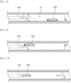
- FIGS. 6 to 10 are views sequentially showing a process of treating a vascular disease of a human body by using the catheter system of the present invention.
- the magnetic robot 200 is moved to the vicinity of a lesion 20 while being coupled to the catheter module 100.
- the magnetic robot 200 may inject drugs and contrast agents while being coupled to the catheter module 100.
- the drugs and the contrast agents may be supplied through the catheter module 100 and supplied toward the lesion 20 through the gap between the coupling ring 120 and the coupling region 220.
- a rotating magnetic field M is applied from the magnetic field generator, the magnetic robot 200 is rotated and a propulsive force F is generated by the spiral protrusion 212 formed on the outer circumferential surface of the magnetic robot.
- the magnetic robot 200 is moved forward by the propulsive force F, and the coupling region 220 is separated from the catheter module 100 when passing through the coupling space 140.
- the magnetic robot 200 separated from the catheter module 100 generates the propulsive force F while being rotated by the rotating magnetic field M and moves near the lesion 20.
- the magnetic robot 200 having arrived at the lesion 20 is rotated at a high speed to remove the lesion 20.
- the drugs and the contrast agents may be injected through the catheter module 100.
- fragments 21 generated during drilling operation of the magnetic robot 200 may be sucked into the catheter module 100 by suction in the catheter module 100.
- the propulsive force may be generated by controlling the external magnetic field or the magnetic robot 200 may be fixed to a blood vessel wall in order to prevent the magnetic robot from being sucked into the catheter module 100 side. Accordingly, the catheter module 100 may suck fragments of the lesion and blood only.
- the rotating magnetic field M is applied to rotate and float the magnetic robot 200, and the magnetic robot 200 is aligned with the catheter module 100.
- the blood is introduced into the catheter module 100, and the magnetic robot 200 is moved toward the catheter module 100 due to the flow of the blood.
- the magnetic robot 200 may sink due to the self-load during the backward movement of the magnetic robot 200, and accordingly the alignment with the catheter module 100 may be disturbed.
- the external magnetic field M may be generated toward the reverse direction of gravity, that is, upward, thereby offsetting the influence of the self-load.
- a rotating magnetic field M is generated in the reverse direction.
- the magnetic robot 200 is rotated in the reverse direction by the rotating magnetic field M to generate the propulsive force F rearward, and the spiral protrusion 231 formed in the first region 230 of the coupling region 220 is coupled to the spiral groove 141 formed inside the coupling space 140.
- the magnetic robot 200 is additionally rotated, the first region 230 is unfastened with the coupling space 140, and the first region 230 is positioned in the decoupling space 130.
- the magnetic robot 200 may idle while the magnetic robot 200 and the catheter module 100 are coupled to each other.
- FIG. 11 shows states in which the catheter module according to the embodiment of the present invention is steered by controlling an external magnetic field.
- FIG. 12 is a view showing a state in which a catheter module according to a comparative example is steered by controlling an external magnetic field.
- the magnetic robot 200 is steered under control of the external magnetic field while being screwed and fixedly coupled to the catheter module 100.
- the drive magnets are expressed to be exposed to the outside to show that the drive magnets are aligned in the direction of the external magnetic field.
- the catheter module 100 is steered while the drive magnet 250 is aligned in the direction of the external magnetic field M.
- the magnetic robot 200 when the external magnetic field M is applied while the direction of the magnetic field of the drive magnet 250 is not aligned with the direction of the external magnetic field, the magnetic robot 200 idles so that the direction of the magnetic field of the drive magnet 250 is aligned in the direction of the external magnetic field M.
- the magnetic robot 200 can be aligned without twisting the catheter 110.
- the catheter system according to an embodiment of the present invention may be used for the treatment of vascular diseases.
Landscapes
- Health & Medical Sciences (AREA)
- Life Sciences & Earth Sciences (AREA)
- Engineering & Computer Science (AREA)
- Surgery (AREA)
- Animal Behavior & Ethology (AREA)
- General Health & Medical Sciences (AREA)
- Biomedical Technology (AREA)
- Heart & Thoracic Surgery (AREA)
- Veterinary Medicine (AREA)
- Public Health (AREA)
- Molecular Biology (AREA)
- Nuclear Medicine, Radiotherapy & Molecular Imaging (AREA)
- Medical Informatics (AREA)
- Biophysics (AREA)
- Pulmonology (AREA)
- Anesthesiology (AREA)
- Hematology (AREA)
- Vascular Medicine (AREA)
- Robotics (AREA)
- Orthopedic Medicine & Surgery (AREA)
- Media Introduction/Drainage Providing Device (AREA)
Abstract
Description
- The present invention relates to a catheter system, and more particularly, to a catheter system capable of separating and coupling a magnetic robot by using a catheter module.
- In general, in order to treat a vascular disease in a blocked or narrowed portion stenosed due to a thrombus or the like, coronary angioplasty is performed in a sequence of inserting a catheter through the femoral artery, widening a blood vessel by a doctor's manual operation and then mounting a device capable of maintaining the widened blood vessel. However, due to the structural characteristics of the catheter, it is difficult to apply the catheter to a complicated blood vessel, and the success of the procedure depends greatly on the skill of the doctor.
- In the existing catheter system, a mechanism has been developed to couple and separate a magnetic robot to/from a catheter tube by using a magnetic force of a permanent magnet and a screw coupling.
-
Korean Registered Patent No. 10-1818400 -
Korean Registered Patent No. 10-1749586 - In addition, in the above two coupling schemes, it is difficult to steer the catheter tube according to the alignment direction between the permanent magnet of the magnetic robot and an external magnetic field while the magnetic robot is coupled to the catheter tube. Specifically, when the external magnetic field is applied while the directions of the permanent magnet of the magnetic robot and the external magnetic field are not aligned, the magnetic robot may be separated in a process in which the magnetic robot is rotated and aligned in the direction of the external magnetic field in the case of magnetic force coupling, and the catheter tube may be twisted due to the rotation of the magnetic robot in the case of screw coupling.
- The present invention provides a catheter system capable of accurately steering a catheter module in the direction of an external magnetic field.
- In addition, the present invention provides a catheter system capable of injecting drugs while a catheter module and the magnetic robot are coupled.
- In addition, the present invention provides a catheter system capable of accurately centering a magnetic robot to a catheter module.
- The catheter system according to the present invention includes: a catheter module; and a magnetic robot to be coupled with the catheter module, wherein the magnetic robot may idle when an external rotating magnetic field is applied at a coupling position with the catheter module.
- In addition, the catheter module may include: a coupling ring sequentially formed therein with a coupling space and a decoupling space having an inner diameter larger than an inner diameter of the coupling space; and a catheter formed of a flexible material and coupled to the coupling ring. Meanwhile, the magnetic robot may include a body having a screw thread shape and formed at a rear end thereof with a coupling region inserted into the coupling ring, and a drive magnet provided inside the body. The coupling region of the magnetic robot may include a first region having an outer diameter corresponding to the inner diameter of the coupling space; and a second region positioned between the first region and the drive magnet and having an outer diameter smaller than the outer diameter of the first region.
- In addition, the coupling space may be formed on an inner circumferential surface thereof with a spiral groove, and the first region may be formed on an outer circumferential surface thereof with a spiral protrusion fastened to the spiral groove.
- In addition, the first region may have a length equal to or less than a length of the decoupling space, and the second region may have a length equal to or greater than a length of the coupling space.
- In addition, the first region may have a flow path recessed inward from the outer circumferential surface of the first region in a longitudinal direction of the body.
- In addition, the body may be formed at a front end thereof with a drilling tip, and the body may be formed on an outer circumferential surface thereof with a spiral protrusion.
- According to the present invention, since the magnetic robot may be co-rotated while the catheter module is coupled to the magnetic robot, the magnetic robot can be aligned in the direction of the external magnetic field without twisting the catheter.
- In addition, according to the present invention, a drug can be injected into the blood vessel through a gap between the coupling ring and the coupling region while the catheter module is coupled to the magnetic robot.
- In addition, according to the present invention, the magnetic robot can be accurately centered to the catheter module under control of the external magnetic field and suction of the catheter module.
-
-
FIG. 1 is a perspective view showing a catheter system according to an embodiment of the present invention##. -
FIG. 2 is a perspective view showing a state in which a catheter module and a magnetic robot are separated from each other in the catheter system ofFIG. 1 . -
FIG. 3 is a sectional view showing the catheter system ofFIG. 1 . -
FIGS. 4 and5 are views showing a magnetic robot according to another embodiment of the present invention. -
FIGS. 6 to 10 are views sequentially showing a process of treating a vascular disease of a human body by using the catheter system of the present invention. -
FIG. 11 shows states in which the catheter module according to the embodiment of the present invention is steered by controlling an external magnetic field. -
FIG. 12 is a view showing a state in which a catheter module according to a comparative example is steered by controlling an external magnetic field. - The catheter system according to an embodiments of the present invention includes: a catheter module; and a magnetic robot to be coupled with the catheter module, wherein the magnetic robot may idle when an external rotating magnetic field is applied at a coupling position with the catheter module.
- Hereinafter, exemplary embodiments of the present invention will be described in detail with reference to the accompanying drawings. However, the technical idea of the present invention is not limited to the exemplary embodiments described herein and may be embodied in other forms. Further, the embodiments are provided to enable contents disclosed herein to be thorough and complete and provided to enable those skilled in the art to fully understand the idea of the present invention.
- In the specification herein, when one component is mentioned as being on other component, it signifies that the one component may be placed directly on the other component or a third component may be interposed therebetween. In addition, in the drawings, thicknesses of films and areas may be exaggerated to effectively describe the technology of the present invention.
- In addition, although terms such as first, second and third are used to describe various components in various embodiments of the present specification, the components will not be limited by the terms. The above terms are used merely to distinguish one component from another. Accordingly, a first component referred to in one component may be referred to as a second component in another embodiment. Each embodiment described and illustrated herein may also include a complementary embodiment. In addition, the term "and/or" is used herein to include at least one of the components listed before and after the term.
- The singular expression herein includes a plural expression unless the context clearly specifies otherwise. In addition, it will be understood that the term such as "include" or "have" herein is intended to designate the presence of feature, number, step, component, or a combination thereof recited in the specification, and does not preclude the possibility of the presence or addition of one or more other features, numbers, steps, components, or combinations thereof. In addition, the term "connection" is used herein to include both indirectly connecting a plurality of components and directly connecting the components.
- In addition, in the following description of the embodiments of the present invention, the detailed description of known functions and configurations incorporated herein will be omitted when it possibly makes the subject matter of the present invention unclear unnecessarily.
-
FIG. 1 is a perspective view illustrating a catheter system according to an embodiment of the present invention;FIG. 2 is a perspective view illustrating a state in which a catheter module and a magnetic robot are separated from each other in the catheter system ofFIG. 1 ; andFIG. 3 is a sectional view illustrating the catheter system ofFIG. 1 . - Referring to
FIGS. 1 to 3 , acatheter system 10 includes acatheter module 100, amagnetic robot 200, and a magnetic field generator (not shown). Thecatheter module 100 may be coupled to and separated from themagnetic robot 200, and may be deployed themagnetic robot 200 to the vicinity of the lesion while themagnetic robot 200 is coupled. - The
catheter module 100 includes acatheter 110 and acoupling ring 120. - The
catheter 110 has a tube shape having a predetermined length and may be inserted into a body tubular tissue. Thecatheter 110 is formed of a deformable flexible material. - The
coupling ring 120 is fixedly coupled to a front end of thecatheter 110. Thecoupling ring 120 has a predetermined length and has an outer diameter corresponding to thecatheter 110. A decouplingspace 130 and acoupling space 140 are sequentially formed inside thecoupling ring 120. Thedecoupling space 130 is formed at a rear end of thecoupling ring 120 adjacent to thecatheter 110, and thecoupling space 140 is formed adjacent to a front end of thecoupling ring 120. An inner diameter of the decouplingspace 130 and an inner diameter of thecoupling space 140 may be different from each other. According to the embodiment, the inner diameter of thedecoupling space 130 may be greater than the inner diameter of thecoupling space 140. - A
spiral groove 141 is formed along a circumference of the inner diameter of thecoupling space 140. Thespiral groove 141 extends from the front end of thecoupling ring 120 to just before thedecoupling space 130. - The
magnetic robot 200 includes abody 210 and adrive magnet 250. - The
body 210 has a predetermined length and is formed of a non-magnetic material. Adrilling tip 211 is formed at a front end of thebody 210, and aspiral protrusion 212 is formed on an outer circumferential surface of the body. Aninner space 213 is formed inside thebody 210. - A
coupling region 220 is provided at a rear end of thebody 210. Thecoupling region 220 refers to a region inserted into thecatheter module 100 when themagnetic robot 200 is coupled to thecatheter module 100, and is provided with a length corresponding to or longer than thecoupling ring 120. - The
coupling region 220 includes afirst region 230 and asecond region 240. Thefirst region 230 is positioned at the rear end of thebody 210, and thesecond region 240 is positioned between thefirst region 210 and theinner space 213. - The
first region 230 has an outer diameter corresponding to an inner diameter of thecoupling space 140, and thesecond region 240 has an outer diameter smaller than thefirst region 230. Aspiral protrusion 231 may be formed along an outer circumferential surface of thefirst region 230. Thespiral protrusion 231 may be fastened to thespiral groove 141 formed in thecoupling ring 120. A length of thefirst region 230 in the longitudinal direction of thebody 210 may be equal to or less than a length of thedecoupling space 130. - The
second region 240 has the outer diameter smaller than the outer diameter of thefirst region 230 and the inner diameter of thecoupling space 140. A length of thesecond region 240 in the longitudinal direction of thebody 210 may be equal to or greater than a length of thecoupling space 140. - Since the outer diameter of the
first region 230 is smaller than the inner diameter of thedecoupling space 130 and the outer diameter of thesecond region 240 is smaller than the inner diameter of thecoupling space 140 while themagnetic robot 200 is coupled to thecatheter module 100, a gap is present between thecoupling ring 120 and thecoupling region 220. Thecatheter module 100 may supply the drug into the blood vessel through the gap while themagnetic robot 200 is coupled thereto. - The
drive magnet 250 is inserted into theinner space 213 of thebody 210 and fixedly coupled to thebody 210. Thedrive magnet 250 is integrally driven with thebody 210. Thedrive magnet 250 has a cylindrical shape and is magnetized in a radial direction of thebody 210. -
FIGS. 4 and5 are views showing a magnetic robot according to another embodiment of the present invention. - Referring to
FIGS. 4 and5 , Aflow path 232 may be formed in thefirst region 230 of thecoupling region 220. Theflow path 232 may be recessed inward from the outer circumferential surface of thefirst region 230 by a predetermined depth. A plurality offlow paths 232 may be spaced apart from each other along the circumference of thefirst region 230, and formed in the longitudinal direction of thebody 210. Since the gap between thecoupling ring 120 and thefirst region 230 is increased by theflow path 232 when themagnetic robot 200 is coupled to thecatheter module 100, the drug may be smoothly supplied through theflow path 232. - Hereinafter, a process of treating a vascular disease of a human body using the above-described
catheter system 10 will be described in detail. -
FIGS. 6 to 10 are views sequentially showing a process of treating a vascular disease of a human body by using the catheter system of the present invention. - First, referring to
FIG. 6 , themagnetic robot 200 is moved to the vicinity of alesion 20 while being coupled to thecatheter module 100. According to one embodiment, themagnetic robot 200 may inject drugs and contrast agents while being coupled to thecatheter module 100. The drugs and the contrast agents may be supplied through thecatheter module 100 and supplied toward thelesion 20 through the gap between thecoupling ring 120 and thecoupling region 220. When a rotating magnetic field M is applied from the magnetic field generator, themagnetic robot 200 is rotated and a propulsive force F is generated by thespiral protrusion 212 formed on the outer circumferential surface of the magnetic robot. Themagnetic robot 200 is moved forward by the propulsive force F, and thecoupling region 220 is separated from thecatheter module 100 when passing through thecoupling space 140. - Referring to
FIG. 7 , themagnetic robot 200 separated from thecatheter module 100 generates the propulsive force F while being rotated by the rotating magnetic field M and moves near thelesion 20. Themagnetic robot 200 having arrived at thelesion 20 is rotated at a high speed to remove thelesion 20. At this timing, the drugs and the contrast agents may be injected through thecatheter module 100. - Referring to
FIG. 8 , fragments 21 generated during drilling operation of themagnetic robot 200 may be sucked into thecatheter module 100 by suction in thecatheter module 100. At this timing, the propulsive force may be generated by controlling the external magnetic field or themagnetic robot 200 may be fixed to a blood vessel wall in order to prevent the magnetic robot from being sucked into thecatheter module 100 side. Accordingly, thecatheter module 100 may suck fragments of the lesion and blood only. - Referring to
FIG. 9 , when the suction of thefragments 21 is completed, the rotating magnetic field M is applied to rotate and float themagnetic robot 200, and themagnetic robot 200 is aligned with thecatheter module 100. In this state, when a negative pressure is applied into thecatheter module 100, the blood is introduced into thecatheter module 100, and themagnetic robot 200 is moved toward thecatheter module 100 due to the flow of the blood. Themagnetic robot 200 may sink due to the self-load during the backward movement of themagnetic robot 200, and accordingly the alignment with thecatheter module 100 may be disturbed. In order to prevent this, the external magnetic field M may be generated toward the reverse direction of gravity, that is, upward, thereby offsetting the influence of the self-load. - Referring to
FIG. 10 , when thecoupling region 220 of themagnetic robot 200 is positioned inside thecoupling ring 120, a rotating magnetic field M is generated in the reverse direction. Themagnetic robot 200 is rotated in the reverse direction by the rotating magnetic field M to generate the propulsive force F rearward, and thespiral protrusion 231 formed in thefirst region 230 of thecoupling region 220 is coupled to thespiral groove 141 formed inside thecoupling space 140. When themagnetic robot 200 is additionally rotated, thefirst region 230 is unfastened with thecoupling space 140, and thefirst region 230 is positioned in thedecoupling space 130. - As described above, in the
catheter system 10 according to the present invention, themagnetic robot 200 may idle while themagnetic robot 200 and thecatheter module 100 are coupled to each other. -
FIG. 11 shows states in which the catheter module according to the embodiment of the present invention is steered by controlling an external magnetic field.FIG. 12 is a view showing a state in which a catheter module according to a comparative example is steered by controlling an external magnetic field. In the comparative example, themagnetic robot 200 is steered under control of the external magnetic field while being screwed and fixedly coupled to thecatheter module 100. InFIGS. 11 and 12 , the drive magnets are expressed to be exposed to the outside to show that the drive magnets are aligned in the direction of the external magnetic field. - First, referring to
FIG. 11 , In the process of deploying themagnetic robot 200 in the vicinity of the lesion by thecatheter module 100, thecatheter module 100 is steered while thedrive magnet 250 is aligned in the direction of the external magnetic field M. - As shown in
FIG. 12 , when the external magnetic field M is applied in a state in which themagnetic robot 200 is fixedly coupled to thecatheter module 100 and the direction of the magnetic field of thedrive magnet 250 is not aligned with the direction of the external magnetic field, thedrive magnet 250 is rotated and aligned in the direction of the external magnetic field M. At this time, when thedrive magnet 250 is rotated in the coupling direction between themagnetic robot 200 and thecatheter module 100, thecatheter module 100 is rotated together, thereby twisting thecatheter 110. On the other hand, when thedrive magnet 250 is rotated in the decoupling direction between themagnetic robot 200 and thecatheter module 100, the coupling between themagnetic robot 200 and thecatheter module 100 may be decoupled. In addition, when thedrive magnet 250 has a large rotation size, a coupling portion between themagnetic robot 200 and thecatheter module 100 may be damaged. In this state, when thecatheter module 100 is steered, it is difficult to accurately control the direction. - However, in the present invention, when the external magnetic field M is applied while the direction of the magnetic field of the
drive magnet 250 is not aligned with the direction of the external magnetic field, themagnetic robot 200 idles so that the direction of the magnetic field of thedrive magnet 250 is aligned in the direction of the external magnetic field M. Thus, themagnetic robot 200 can be aligned without twisting thecatheter 110. - Although the present invention has been described in detail using exemplary embodiments, the scope of the present invention is not limited to a specific embodiment and will be interpreted by the appended claims. Further, it will be understood by a person having ordinary skill in the art that many modifications and variations are possible without departing from the scope of the present invention.
- The catheter system according to an embodiment of the present invention may be used for the treatment of vascular diseases.
Claims (6)
- A catheter system comprising:a catheter module; anda magnetic robot coupled to catheter module, whereinthe magnetic robot idles when an external rotating magnetic field is applied at a coupling position with the catheter module.
- The catheter system of claim 1, wherein the catheter module includes:a coupling ring sequentially formed therein with a coupling space and a decoupling space having an inner diameter larger than an inner diameter of the coupling space; anda catheter formed of a flexible material and coupled to the coupling ring, whereinthe magnetic robot includes:a body formed at a rear end thereof with a coupling region inserted into the coupling ring; anda drive magnet provided inside the body, and wherein the coupling region has:a first region having an outer diameter corresponding to the inner diameter of the coupling space; anda second region positioned between the first region and the drive magnet and having an outer diameter smaller than the outer diameter of the first region.
- The catheter system of claim 2, wherein the coupling space is formed on an inner circumferential surface thereof with a spiral groove, and
the first region is formed on an outer circumferential surface thereof with a spiral protrusion fastened to the spiral groove. - The catheter system of claim 2, wherein the first region has a length equal to or less than a length of the decoupling space, and
the second region has a length equal to or greater than a length of the coupling space. - The catheter system of claim 2, wherein the first region has a flow path recessed inward from an outer circumferential surface of the first region in a longitudinal direction of the body.
- The catheter system of claim 2, wherein the body is formed at a front end thereof with a drilling tip, and formed on an outer circumferential surface thereof with a spiral protrusion.
Applications Claiming Priority (2)
| Application Number | Priority Date | Filing Date | Title |
|---|---|---|---|
| KR1020210164662A KR102665852B1 (en) | 2021-11-25 | 2021-11-25 | Catheter system |
| PCT/KR2022/018439 WO2023096289A1 (en) | 2021-11-25 | 2022-11-21 | Catheter system |
Publications (2)
| Publication Number | Publication Date |
|---|---|
| EP4427786A1 true EP4427786A1 (en) | 2024-09-11 |
| EP4427786A4 EP4427786A4 (en) | 2025-10-22 |
Family
ID=86539995
Family Applications (1)
| Application Number | Title | Priority Date | Filing Date |
|---|---|---|---|
| EP22898971.1A Pending EP4427786A4 (en) | 2021-11-25 | 2022-11-21 | CATHETER SYSTEM |
Country Status (4)
| Country | Link |
|---|---|
| EP (1) | EP4427786A4 (en) |
| KR (1) | KR102665852B1 (en) |
| CN (1) | CN118302220A (en) |
| WO (1) | WO2023096289A1 (en) |
Family Cites Families (9)
| Publication number | Priority date | Publication date | Assignee | Title |
|---|---|---|---|---|
| JP4037693B2 (en) * | 2002-06-17 | 2008-01-23 | オリンパス株式会社 | Medical device and treatment tool |
| US9023033B2 (en) * | 2010-08-04 | 2015-05-05 | St. Jude Medical, Atrial Fibrillation Division, Inc. | Magnetically guided catheters |
| ES3015082T3 (en) * | 2012-05-19 | 2025-04-29 | Taris Biomedical Llc | Implantable urological device with retrieval feature |
| KR101471526B1 (en) * | 2014-05-07 | 2014-12-12 | 한양대학교 산학협력단 | Medical micro robot and micro robot system having the same |
| WO2016094430A1 (en) * | 2014-12-09 | 2016-06-16 | Baylor College Of Medicine | Magnetic assisted in-situ tubular stentgraft fenestration |
| KR101749586B1 (en) | 2015-12-24 | 2017-06-21 | 재단법인대구경북과학기술원 | Magnetically actuated micro robot based catheter with wireless power transform and it's control method |
| KR101818400B1 (en) | 2017-08-11 | 2018-01-15 | 한양대학교 산학협력단 | Magnetic Robot System |
| KR102084618B1 (en) * | 2018-08-29 | 2020-03-04 | 계명대학교 산학협력단 | A boring device to pass true lumen of chronic total occlusion lesion |
| KR102348773B1 (en) * | 2019-07-26 | 2022-01-07 | 한양대학교 산학협력단 | Catheter system |
-
2021
- 2021-11-25 KR KR1020210164662A patent/KR102665852B1/en active Active
-
2022
- 2022-11-21 CN CN202280078318.4A patent/CN118302220A/en active Pending
- 2022-11-21 WO PCT/KR2022/018439 patent/WO2023096289A1/en not_active Ceased
- 2022-11-21 EP EP22898971.1A patent/EP4427786A4/en active Pending
Also Published As
| Publication number | Publication date |
|---|---|
| EP4427786A4 (en) | 2025-10-22 |
| KR102665852B1 (en) | 2024-05-14 |
| KR20230077802A (en) | 2023-06-02 |
| CN118302220A (en) | 2024-07-05 |
| WO2023096289A1 (en) | 2023-06-01 |
Similar Documents
| Publication | Publication Date | Title |
|---|---|---|
| EP3141199B1 (en) | Medical micro-robot and micro-robot system having same | |
| US8231607B2 (en) | Suction catheter and suction-catheter system | |
| US20200246087A1 (en) | Magnetic robot system | |
| CN115038394B (en) | Catheter system | |
| JP2007252960A (en) | Protector for balloon catheter | |
| JP2004248987A (en) | Guide-wire inserting tool | |
| CN114173697B (en) | Catheter system | |
| KR102496728B1 (en) | Magnetic catheter | |
| KR102665852B1 (en) | Catheter system | |
| JPH1099440A (en) | Catheter device and priming apparatus for it | |
| KR102348773B1 (en) | Catheter system | |
| US12396749B2 (en) | Magnetic catheter | |
| WO2021199212A1 (en) | Medical device | |
| CN119523705B (en) | A conveyor handle and its conveying system | |
| JP2019170654A (en) | Medical appliance | |
| CN119053296A (en) | Magnetic robot | |
| JP2005261735A (en) | Endoscopic injection needle and endoscopic treatment system | |
| JPH08224313A (en) | Catheter inserting method | |
| JP2008036026A (en) | Medical equipment device | |
| JP2025041334A (en) | Suction catheter | |
| JP2004194943A (en) | Catheter with ball |
Legal Events
| Date | Code | Title | Description |
|---|---|---|---|
| STAA | Information on the status of an ep patent application or granted ep patent |
Free format text: STATUS: THE INTERNATIONAL PUBLICATION HAS BEEN MADE |
|
| PUAI | Public reference made under article 153(3) epc to a published international application that has entered the european phase |
Free format text: ORIGINAL CODE: 0009012 |
|
| STAA | Information on the status of an ep patent application or granted ep patent |
Free format text: STATUS: REQUEST FOR EXAMINATION WAS MADE |
|
| 17P | Request for examination filed |
Effective date: 20240606 |
|
| AK | Designated contracting states |
Kind code of ref document: A1 Designated state(s): AL AT BE BG CH CY CZ DE DK EE ES FI FR GB GR HR HU IE IS IT LI LT LU LV MC ME MK MT NL NO PL PT RO RS SE SI SK SM TR |
|
| DAV | Request for validation of the european patent (deleted) | ||
| DAX | Request for extension of the european patent (deleted) | ||
| A4 | Supplementary search report drawn up and despatched |
Effective date: 20250919 |
|
| RIC1 | Information provided on ipc code assigned before grant |
Ipc: A61M 25/01 20060101AFI20250915BHEP Ipc: A61M 25/00 20060101ALI20250915BHEP Ipc: A61B 17/3207 20060101ALI20250915BHEP Ipc: A61B 17/00 20060101ALI20250915BHEP Ipc: A61B 34/30 20160101ALI20250915BHEP |