EP4427769B1 - Metering assembly for an implantable infusion apparatus and implantable infusion apparatus with such a metering assembly - Google Patents
Metering assembly for an implantable infusion apparatus and implantable infusion apparatus with such a metering assembly Download PDFInfo
- Publication number
- EP4427769B1 EP4427769B1 EP23160324.2A EP23160324A EP4427769B1 EP 4427769 B1 EP4427769 B1 EP 4427769B1 EP 23160324 A EP23160324 A EP 23160324A EP 4427769 B1 EP4427769 B1 EP 4427769B1
- Authority
- EP
- European Patent Office
- Prior art keywords
- valve
- actuator
- infusate
- metering assembly
- outlet
- Prior art date
- Legal status (The legal status is an assumption and is not a legal conclusion. Google has not performed a legal analysis and makes no representation as to the accuracy of the status listed.)
- Active
Links
Images


Classifications
-
- A—HUMAN NECESSITIES
- A61—MEDICAL OR VETERINARY SCIENCE; HYGIENE
- A61M—DEVICES FOR INTRODUCING MEDIA INTO, OR ONTO, THE BODY; DEVICES FOR TRANSDUCING BODY MEDIA OR FOR TAKING MEDIA FROM THE BODY; DEVICES FOR PRODUCING OR ENDING SLEEP OR STUPOR
- A61M5/00—Devices for bringing media into the body in a subcutaneous, intra-vascular or intramuscular way; Accessories therefor, e.g. filling or cleaning devices, arm-rests
- A61M5/14—Infusion devices, e.g. infusing by gravity; Blood infusion; Accessories therefor
- A61M5/142—Pressure infusion, e.g. using pumps
-
- A—HUMAN NECESSITIES
- A61—MEDICAL OR VETERINARY SCIENCE; HYGIENE
- A61M—DEVICES FOR INTRODUCING MEDIA INTO, OR ONTO, THE BODY; DEVICES FOR TRANSDUCING BODY MEDIA OR FOR TAKING MEDIA FROM THE BODY; DEVICES FOR PRODUCING OR ENDING SLEEP OR STUPOR
- A61M5/00—Devices for bringing media into the body in a subcutaneous, intra-vascular or intramuscular way; Accessories therefor, e.g. filling or cleaning devices, arm-rests
- A61M5/14—Infusion devices, e.g. infusing by gravity; Blood infusion; Accessories therefor
- A61M5/142—Pressure infusion, e.g. using pumps
- A61M5/14244—Pressure infusion, e.g. using pumps adapted to be carried by the patient, e.g. portable on the body
- A61M5/14276—Pressure infusion, e.g. using pumps adapted to be carried by the patient, e.g. portable on the body specially adapted for implantation
-
- A—HUMAN NECESSITIES
- A61—MEDICAL OR VETERINARY SCIENCE; HYGIENE
- A61M—DEVICES FOR INTRODUCING MEDIA INTO, OR ONTO, THE BODY; DEVICES FOR TRANSDUCING BODY MEDIA OR FOR TAKING MEDIA FROM THE BODY; DEVICES FOR PRODUCING OR ENDING SLEEP OR STUPOR
- A61M5/00—Devices for bringing media into the body in a subcutaneous, intra-vascular or intramuscular way; Accessories therefor, e.g. filling or cleaning devices, arm-rests
- A61M5/14—Infusion devices, e.g. infusing by gravity; Blood infusion; Accessories therefor
- A61M5/142—Pressure infusion, e.g. using pumps
- A61M5/145—Pressure infusion, e.g. using pumps using pressurised reservoirs, e.g. pressurised by means of pistons
-
- A—HUMAN NECESSITIES
- A61—MEDICAL OR VETERINARY SCIENCE; HYGIENE
- A61M—DEVICES FOR INTRODUCING MEDIA INTO, OR ONTO, THE BODY; DEVICES FOR TRANSDUCING BODY MEDIA OR FOR TAKING MEDIA FROM THE BODY; DEVICES FOR PRODUCING OR ENDING SLEEP OR STUPOR
- A61M5/00—Devices for bringing media into the body in a subcutaneous, intra-vascular or intramuscular way; Accessories therefor, e.g. filling or cleaning devices, arm-rests
- A61M5/14—Infusion devices, e.g. infusing by gravity; Blood infusion; Accessories therefor
- A61M5/168—Means for controlling media flow to the body or for metering media to the body, e.g. drip meters, counters ; Monitoring media flow to the body
- A61M5/16804—Flow controllers
- A61M5/16809—Flow controllers by repeated filling and emptying of an intermediate volume
-
- A—HUMAN NECESSITIES
- A61—MEDICAL OR VETERINARY SCIENCE; HYGIENE
- A61M—DEVICES FOR INTRODUCING MEDIA INTO, OR ONTO, THE BODY; DEVICES FOR TRANSDUCING BODY MEDIA OR FOR TAKING MEDIA FROM THE BODY; DEVICES FOR PRODUCING OR ENDING SLEEP OR STUPOR
- A61M5/00—Devices for bringing media into the body in a subcutaneous, intra-vascular or intramuscular way; Accessories therefor, e.g. filling or cleaning devices, arm-rests
- A61M5/14—Infusion devices, e.g. infusing by gravity; Blood infusion; Accessories therefor
- A61M5/168—Means for controlling media flow to the body or for metering media to the body, e.g. drip meters, counters ; Monitoring media flow to the body
- A61M5/16877—Adjusting flow; Devices for setting a flow rate
- A61M5/16881—Regulating valves
-
- A—HUMAN NECESSITIES
- A61—MEDICAL OR VETERINARY SCIENCE; HYGIENE
- A61M—DEVICES FOR INTRODUCING MEDIA INTO, OR ONTO, THE BODY; DEVICES FOR TRANSDUCING BODY MEDIA OR FOR TAKING MEDIA FROM THE BODY; DEVICES FOR PRODUCING OR ENDING SLEEP OR STUPOR
- A61M5/00—Devices for bringing media into the body in a subcutaneous, intra-vascular or intramuscular way; Accessories therefor, e.g. filling or cleaning devices, arm-rests
- A61M5/14—Infusion devices, e.g. infusing by gravity; Blood infusion; Accessories therefor
- A61M5/168—Means for controlling media flow to the body or for metering media to the body, e.g. drip meters, counters ; Monitoring media flow to the body
- A61M5/172—Means for controlling media flow to the body or for metering media to the body, e.g. drip meters, counters ; Monitoring media flow to the body electrical or electronic
-
- A—HUMAN NECESSITIES
- A61—MEDICAL OR VETERINARY SCIENCE; HYGIENE
- A61M—DEVICES FOR INTRODUCING MEDIA INTO, OR ONTO, THE BODY; DEVICES FOR TRANSDUCING BODY MEDIA OR FOR TAKING MEDIA FROM THE BODY; DEVICES FOR PRODUCING OR ENDING SLEEP OR STUPOR
- A61M39/00—Tubes, tube connectors, tube couplings, valves, access sites or the like, specially adapted for medical use
- A61M39/22—Valves or arrangement of valves
- A61M39/24—Check- or non-return valves
- A61M2039/2473—Valve comprising a non-deformable, movable element, e.g. ball-valve, valve with movable stopper or reciprocating element
- A61M2039/248—Ball-valve
-
- A—HUMAN NECESSITIES
- A61—MEDICAL OR VETERINARY SCIENCE; HYGIENE
- A61M—DEVICES FOR INTRODUCING MEDIA INTO, OR ONTO, THE BODY; DEVICES FOR TRANSDUCING BODY MEDIA OR FOR TAKING MEDIA FROM THE BODY; DEVICES FOR PRODUCING OR ENDING SLEEP OR STUPOR
- A61M2205/00—General characteristics of the apparatus
- A61M2205/02—General characteristics of the apparatus characterised by a particular materials
- A61M2205/0272—Electro-active or magneto-active materials
- A61M2205/0294—Piezoelectric materials
-
- A—HUMAN NECESSITIES
- A61—MEDICAL OR VETERINARY SCIENCE; HYGIENE
- A61M—DEVICES FOR INTRODUCING MEDIA INTO, OR ONTO, THE BODY; DEVICES FOR TRANSDUCING BODY MEDIA OR FOR TAKING MEDIA FROM THE BODY; DEVICES FOR PRODUCING OR ENDING SLEEP OR STUPOR
- A61M2205/00—General characteristics of the apparatus
- A61M2205/04—General characteristics of the apparatus implanted
-
- A—HUMAN NECESSITIES
- A61—MEDICAL OR VETERINARY SCIENCE; HYGIENE
- A61M—DEVICES FOR INTRODUCING MEDIA INTO, OR ONTO, THE BODY; DEVICES FOR TRANSDUCING BODY MEDIA OR FOR TAKING MEDIA FROM THE BODY; DEVICES FOR PRODUCING OR ENDING SLEEP OR STUPOR
- A61M2205/00—General characteristics of the apparatus
- A61M2205/10—General characteristics of the apparatus with powered movement mechanisms
- A61M2205/106—General characteristics of the apparatus with powered movement mechanisms reciprocating
-
- A—HUMAN NECESSITIES
- A61—MEDICAL OR VETERINARY SCIENCE; HYGIENE
- A61M—DEVICES FOR INTRODUCING MEDIA INTO, OR ONTO, THE BODY; DEVICES FOR TRANSDUCING BODY MEDIA OR FOR TAKING MEDIA FROM THE BODY; DEVICES FOR PRODUCING OR ENDING SLEEP OR STUPOR
- A61M2205/00—General characteristics of the apparatus
- A61M2205/27—General characteristics of the apparatus preventing use
- A61M2205/276—General characteristics of the apparatus preventing use preventing unwanted use
Definitions
- This invention relates to a metering assembly according to the preamble of claim 1.
- US patent number 5,049,141 discloses an implantable infusion apparatus comprising a metering assembly having the features of the preamble of claim 1.
- the prior art implantable infusion apparatus is intended for the delivery of an infusate, i.e., a medical fluid or a fluid drug, to a patient and comprises a pressurized infusate reservoir, an infusate dispensing member and said metering assembly.
- the infusate reservoir is filled with said infusate and pressurized at a pressure above the pressure inside the patient's body.
- the infusate dispensing member of the prior art apparatus is in the form of a catheter and configured to dispense infusate from the infusate reservoir to a site inside the patient's body.
- the metering assembly is configured to control the amount of infusate to be infused per unit of time, i.e., the drug dosage.
- the prior art metering assembly comprises an infusate accumulator with an accumulator volume and a pair of normally closed valves, i.e., an inlet valve and an outlet valve.
- the inlet valve controls the inlet of infusate from the reservoir into the accumulator volume.
- the outlet valve controls the outlet of infusate from the accumulator volume to the infusate dispensing member.
- the inlet valve In a first state, the inlet valve is open and the outlet valve is closed, thereby allowing an infusate flow from the pressurized infusate reservoir into the accumulator volume while blocking an infusate flow from the accumulator volume through the dispensing member. In a second state, the inlet valve is closed and the outlet valve is open, thereby allowing an infusate flow from the accumulator volume through the dispensing member while blocking an infusate flow from the pressurized infusate reservoir into the accumulator volume.
- the accumulator volume has a pressure intermediate between the pressure of the pressurized infusate reservoir and the pressure inside the patient's body.
- infusate accumulated inside the accumulator volume is "pumped" from the accumulator volume into the infusate dispensing member and thus into the patient's body. Cycling between the first and second state allows to control the infused drug dosage, wherein increasing the rate of cycling increases the infused volume per unit of time and thus the dosage of the drug.
- the prior art metering assembly comprises an actuator device configured for actuating the inlet valve and the outlet valve between said first and second states.
- the actuator device of the prior art metering assembly comprises two separate actuators for controlling the open and close cycles of the inlet valve and the outlet valve.
- Said separate actuators are in the form of electronically controlled solenoids, a first solenoid actuating the inlet valve and a second solenoid actuating the outlet valve.
- MRI magnetic resonance imaging
- US 2011/060318 A1 discloses an implantable pump for providing metered doses of a compound to an individual.
- the implantable pump includes a chamber for storing an individual dose of the compound, an inlet valve fluidly coupled to the chamber for controlling a flow of the compound into the chamber, and an outlet valve fluidly coupled to the chamber for controlling a flow of the compound out of the chamber and into the individual.
- the pump includes an inlet valve driver circuit operable for opening and closing the inlet valve, and an outlet valve driver circuit operable for opening and closing the outlet valve.
- a battery and a charging circuit that includes a capacitor are included in the implantable pump.
- the charging circuit is operatively coupled to the battery for charging of the capacitor.
- the charged capacitor is operable for supplying power to the valve driver circuits.
- WO 2021/067674 A1 discloses an implantable drug delivery device and a method that includes a sensor device for detecting deflection of a diaphragm at a first time from a first position within a diaphragm chamber of an accumulator of the implantable drug delivery device.
- a cycle count may be incremented in response to the diaphragm returning to the first position within the diaphragm chamber, each time during cyclical deflections within the diaphragm chamber.
- a flow rate of infusate may be determined based on a volume of the diaphragm chamber, the cycle count, and an elapsed time since the first time. Once the flow rate is determined, a processor may determine whether the flow rate of infusate is normal based on a comparison of the determined flow rate to at least one threshold flow rate.
- the actuator device with an actuator movable between a first position and a second position for alternating actuation of the inlet valve or the outlet valve between the first state and the second state, wherein in the first position, the actuator mechanically actuates the inlet valve and does not actuate the outlet valve, and wherein in the second position, the actuator mechanically actuates the outlet valve and does not actuate the inlet valve. Due to the alternating mechanical actuation of both the inlet valve and the outlet valve by means of one and the same actuator, simultaneously actuating both valves is not possible. Consequently, opening the inlet valve and the outlet valve at the same time and a resulting uncontrolled infusate delivery is not possible. This leads to an improved safety.
- the actuator is differently movable between the first position and the second position.
- the actuator moves linearly and/or in translation.
- the actuator moves rotationally.
- the actuator moves pivotally.
- a combined linear, rotational and/or pivotal motion of the actuator is also possible and envisaged.
- the movement between the first position and the second position can be the result of a rigid body motion of the actuator, an elastic deformation of at least a portion of the actuator or a combination of both.
- Both valves are normally closed, i.e., in a closed state blocking infusate flow if and when not actuated by means of the actuator. Consequently, the first position of the actuator controls the first state and the second position of the actuator controls the second state.
- the inlet valve and the outlet valve each comprise a biasing member configured for biasing the respective valve into its closed position.
- both valves each comprise a closing mechanism configured to keep the respective valve closed if and when not actuated.
- the actuator actuates the valves in different ways.
- the actuator is configured to open the valves by means of a pushing motion and/or a pushing force.
- the actuator is configured to open the valves by means of a pulling motion and/or a pulling force. In yet another embodiment, the actuator is configured to open the valves by means of a turning motion and/or a torque.
- the mechanical action of the actuator on the inlet valve and the outlet valve can be direct or indirect. In one embodiment, a portion of the actuator alternately directly contacts a portion of the inlet valve or a portion of the outlet valve, said contacts transmitting a force and/or motion of the actuator onto the respective valve in order to open it. In another embodiment, said alternating contact is indirect, the actuator acting on a transmitting member which in turn (directly) acts on the respective valve.
- the pressurized infusate reservoir and the infusate dispensing member do not form components of the metering assembly but instead of the implantable infusion apparatus.
- the infusate reservoir is configured to contain and pressurize the infusate by known techniques, for example by means of a two-phase fluid induced pressure.
- Technical details of the pressurized infusate reservoir are not essential to the present invention and therefore omitted.
- the infusate dispensing member is a catheter.
- technical details of the infusate dispensing member are not essential to the present invention and therefore omitted. The same applies, mutatis mutandis, regarding the infusate accumulator with the accumulator volume.
- the accumulator volume is formed by means of a diaphragm arranged in an accumulator chamber of the infusate accumulator, wherein said diaphragm is deflectable by means of the infusate inflow from the pressurized infusate reservoir while the valves reside in the first state.
- the pressure on a back side of the diaphragm can be said intermediate pressure causing the described "pumping" action of the infusate accumulator.
- other infusate accumulator designs are possible and envisaged.
- the actuator comprises an actuator member alternately acting on the inlet valve or the outlet valve, and a force generating member operatively coupled with the actuator member and configured for generating a force and/or motion for moving the actuator member between the first position and the second position.
- the actuator member is a lever arm pivotally movable and/or flexibly bendable between the first position and the second position.
- the actuator member is a push rod or a pull rod linearly movable between the first and second position.
- the actuator member is a cam member rotationally movable between the first and second position.
- the force generating member is configured to generate a force and/or motion for moving the actuator member between the first and second position.
- the force generating member is configured to move the actuator member from the first position into the second position, while moving the actuator member from the second position into the first position is not possible by means of the force generating member.
- the force generating member is configured for moving the actuator member from the second position into the first position, while a reverse positioning is not possible by means of the force generating member.
- the actuator preferably comprises a biasing member operatively coupled with the actuator member which biases the actuator member into the not actively actuated position.
- the force generating member is configured to move the actuator member in both positions which allows to omit said biasing member.
- the force generating member is a piezoelectric element.
- the force generating member relies on other physical operating principles, for example a hydraulic, pneumatic, magnetic principle to generate said force and/or motion.
- the actuator comprises a biasing member operatively coupled with the actuator member and biasing the actuator member against the force and/or motion of the force generating member.
- a biasing member operatively coupled with the actuator member and biasing the actuator member against the force and/or motion of the force generating member. This enables the use of a single-direction force generating member which is configured to move the actuator member from the first position into the second position or vice versa but not alternately between both positions. Consequently, a further design simplification and cost reductions can be achieved.
- the biasing member is a spring element, preferably in the form of a helical spring. In another embodiment, the biasing member is an elastomeric element or the like.
- the actuator member is a lever arm movable between the first position and the second position by means of the force generating member, the lever arm amplifying the motion of the force generating member into an amplified actuation motion.
- the lever arm leverages the motion of the force generating member. This allows to employ a force generating member having a relatively small range of motion/displacement which, without leveraging, would not suffice to actuate the valves.
- the lever arm has a positive mechanical advantage regarding the motion of the force generating member.
- said mechanical advantage is in a range between 1:5 and 1:60, preferably between 1:10 and 1:30, more preferably at least approximately 1:20. Consequently, due to the basic mechanical principles involved, the mechanical advantage on the force of the force generating member is negative.
- the lever arm is hinged at a pivot and pivotally movable between the first position and the second position.
- the pivot for example, is in the form of a pin, a fulcrum or the like.
- the lever arm is at least substantially rigid, the motion of the lever arm between the first and the second position, consequently, being a rigid body motion. This embodiment allows for a further simplified and yet more robust design.
- the lever arm is fixedly mounted and flexibly bendable between the first position and the second position.
- at least a portion of the lever arm is elastic and/or pliable in order to allow a flexible bending motion between the first and the second position. This can be achieved by choosing appropriate elastic material and/or geometric properties of the lever arm. Since there is no need for a pivot and/or fulcrum, this embodiment allows for a very simple and very robust design.
- the inlet valve and the outlet valve are arranged at one end of the lever arm, said end of the lever arm alternately acting on both valves.
- the inlet valve and the outlet valve are arranged at opposing first and second ends of the lever arm, wherein the first end acts on the inlet valve and the second end acts on the outlet valve.
- the lever arm moves like a rocker or seesaw between the first position and the second position.
- the force generating member is a piezoelectric element, preferably in the form of a piezo stack.
- Piezoelectric elements are often referred to as piezoelectric actuators and work on the basis of known physical principles. Energizing the piezoelectric element causes the piezoelectric element to expand and/or extend. Deenergizing causes the piezoelectric element to return to its unexpanded/unextended (original) dimensions.
- Using a piezo stack which is a known form of piezoelectric element, allows for a slender design while providing a relatively large range of motion/displacement of the force generating element.
- the piezoelectric element is a highly useful component as it has the ability to change shape in response to voltage.
- the degree of expansion varies depending on both the length of the piezoelectric element and the voltage applied. This means that the longer the piezoelectric element and the higher the voltage, the greater the expansion.
- the material of the piezoelectric element generates a blocking force that relies on both the voltage and the cross-section of the piezoelectric element. A larger cross-section and higher voltage result in a greater blocking force that it can generate and transmit.
- the present invention takes advantage of the unique characteristics of the piezoelectric element/its material. In one embodiment its expansion is used and amplified using said lever arm to reach the desired amount of movement. This ensures operation within the required force's working range, while still achieving the desired displacement.
- the inlet valve and the outlet valve each comprise a movable ball valve element, a fixed valve seat and a biasing element, which biases the ball element into the valve seat, wherein the actuator at least indirectly acts on the ball valve element.
- the biasing element is a spring element, in particular a helical spring. The biasing element pushes the ball valve element into the valve seat, thereby biasing the respective valve into its closed position.
- the actuator directly acts on the ball valve element for opening the respective valve.
- said action is indirect via a transmitting member or the like.
- the inlet valve and the outlet valve each comprise an axially movable transmitting member longitudinally extending between a first end and a second end, wherein the first end of the transmitting member is configured for contacting the actuator and the second end of the transmitting member is configured for contacting the ball valve element.
- the transmitting member is configured to transmit the force and/or motion of the force generating member onto the respective valve, in particular onto the respective ball valve element.
- the transmitting member can have a single-part or a multi-part design. This embodiment allows to arrange the actuator further away from the valves and with this further away from fluid carrying components/portions of the metering assembly.
- the invention further relates to an implantable infusion apparatus comprising a metering assembly according to the preceding disclosure, and further comprising a pressurized infusate reservoir and an infusate dispensing member, wherein the inlet conduit of the metering assembly is in fluid communication with the infusate reservoir, and wherein the outlet conduit of the metering assembly is in fluid communication with the infusate dispensing member.
- an implantable infusion apparatus 1 comprises a pressurized infusate reservoir 2, an infusate dispensing member 3 and a metering assembly 4.
- the implantable infusion apparatus 1 is configured for the delivery of infusate F, i.e., a medical fluid or fluid drug, to a patient.
- infusate F i.e., a medical fluid or fluid drug
- the infusate reservoir 2 contains a pressurized volume of the infusate F to be infused. Inside the infusate reservoir 2, the infusate F is pressurized with a reservoir pressure p 1 .
- the reservoir pressure p 1 is generated by means of known techniques and can be constant or varying.
- Technical details of the pressurized infusate reservoir 2 are not within the focus of the present invention. A more detailed description of the specific design and function of the pressurized infusate reservoir 2 is therefore not necessary.
- the infusate dispensing member 3 is configured for dispensing infusate F from the infusate reservoir 2 to a site inside the patient's body B.
- the infusate dispensing member 3 is fluidly connected with the infusate reservoir 2 via the metering assembly 4.
- the infusate dispensing member 3 is a catheter 31 having a distal end 32 and a proximal end 33.
- the distal end 32 can also be referred to as catheter tip and is located at said site inside the body B.
- the proximal end 33 is fluidly connected with the metering assembly 4.
- the pressurized infusate reservoir 2 and the metering assembly 4 are arranged in a housing which is not depicted in detail.
- the housing containing the infusate reservoir 2 and the metering assembly 4 is made of a biocompatible material and implanted into the patient's body B.
- the pressurized infusate reservoir and the metering assembly each comprise a separate housing, said housings being implanted at different locations of the patient's body.
- the metering assembly 4 comprises an inlet conduit 5, an outlet conduit 6, an infusate accumulator 7 having an accumulator volume 8, an inlet valve 9, an outlet valve 10 and an actuator device 11.
- the inlet conduit 5 is fluidly connected with the pressurized infusate reservoir 2. Said fluid connection is schematically depicted by means of the broken line extending between the infusate reservoir 2 and the inlet conduit 5 as shown in Fig. 1 .
- the inlet conduit 5 is configured for receiving an infusate flow from the pressurized infusate reservoir 2.
- the outlet conduit 6 is fluidly connected with the infusate dispensing member 3. Said fluid connection is schematically depicted by the broken line extending between the outlet conduit 6 and the fluid dispensing member 3 as shown in Fig. 1 .
- the outlet conduit 6 is configured for delivering an infusate flow to the fluid dispensing member 3, i.e., the catheter 31.
- the outlet conduit 6 is fluidly connected with the proximal end 33 of the fluid dispensing member 3 in form of the catheter 31.
- the infusate accumulator 7 comprises the accumulator volume 8.
- the infusate accumulator 7 is configured for accumulating a defined fixed volume of infusate received from the infusate reservoir 2 and to be delivered to the infusate dispensing member 3. Said fixed volume is accumulated inside the accumulator volume 8.
- the accumulator volume 8 is in line with the inlet conduit 5 and the outlet conduit 6.
- the inlet valve 9 is in fluid communication with the inlet conduit 5 and the accumulator volume 8. In other words, the inlet valve 9 is in line with the inlet conduit 5 and the accumulator volume 8. The inlet valve 9 controls the infusate flow from the infusate reservoir 2 into the accumulator volume 8.
- the outlet valve 10 is in fluid communication with the accumulator volume 8 and the outlet conduit 6. In other words, the outlet valve 10 is in line with the accumulator volume 8 and the outlet conduit 6. The outlet valve 10 controls the infusate flow from the accumulator volume 8 into the fluid dispensing member 3.
- the inlet valve 9 and the outlet valve 10 are both normally closed. This means that infusate flow through the valves 9, 10 is blocked if and when said valves 9, 10 are not actuated by means of the actuator device 11.
- the actuator device 11 is configured for actuating the inlet valve 9 and the outlet valve 10 between a first state and a second state.
- the inlet valve 9 is open and the outlet valve 10 is closed.
- the opened inlet valve 9 allows an infusate flow from the infusate reservoir 2 through the inlet conduit 5 into the accumulator volume 8.
- the closed outlet valve 10 simultaneously blocks an infusate flow from the accumulator volume 8 through the outlet conduit 6 and into the fluid dispensing member 3.
- the inlet valve 9 is closed and the outlet valve 10 is open.
- the closed inlet valve 9 blocks an infusate flow from the infusate reservoir 2 through the inlet conduit 5 into the accumulator volume 8.
- the opened outlet valve 10 allows an infusate flow from the accumulator volume 8 through the outlet conduit 6 into the fluid dispensing member 3.
- Cycling or switching between first state and the second state causes a charging and discharging of the accumulator volume 8, i.e., a "pumping", whereby a rate of switching or cycling defines the amount of infusate F infused per unit of time and therefore the dosage of infusate F delivered to the patient.
- the amount of infusate F per unit of time can also be denoted as infusate rate F R .
- the inlet valve 9 is open and the outlet valve 10 is closed, i.e., the valves 9, 10 are in the aforementioned first state. Consequently, the accumulator device 7 is filled to its fixed accumulator volume 8.
- the full accumulator volume 8 is discharged through the outlet conduit 6 by actuating the valves 9, 10 into the second state (inlet valve 9 closed, outlet valve 10 open).
- the accumulator device 7, more specifically its accumulator volume 8, is alternately filled and emptied by a switching action of the valves 9, 10.
- the accumulator device 7 operates on the basis of known principles and comprises a design which is known at least in principle. Hence, the accumulator device 7 operates at an accumulator pressure p 2 which is intermediate between the reservoir pressure p 1 and a pressure p 3 inside the patient's body B.
- the pressure p 3 inside the patient's body B may be an atmospheric or cardiovascular pressure slightly above the atmospheric pressure. Said pressure setup, i.e., p 1 > p 2 > p 3 , results in the above-described pumping action.
- the accumulator device 7 comprises an accumulator chamber 71, a pressure chamber 72, a diaphragm 73, a back stop surface 74 and a front stop surface 75.
- the diaphragm 73 is arranged in the accumulator chamber 71.
- the diaphragm 73 is deflectable between a first position as depicted in Fig. 1 and a second position.
- the second position of the diaphragm 73 is schematically illustrated with the broken line inside the accumulator chamber shown in Fig. 1 .
- the diaphragm 73 lays flat on the front stop surface 75.
- the diaphragm 73 is deflected from the front stop surface 75 and pressed onto the back stop surface 74, thereby defining said fixed accumulator volume 8 inside the accumulator chamber 71.
- the pressure chamber 72 is pressurized at the accumulator pressure p 2 and in fluid communication with a back surface of the diaphragm 73 which opposes the accumulator volume 8. It is worth mentioning, that embodiments not shown in the figures, do not comprise a pressure chamber 72.
- the accumulator volume 8 is empty when the diaphragm 73 is in its first position. Opening the inlet valve 9 while keeping the outlet valve 10 closed, causes the inflowing infusate to deflect the diaphragm 73 into its second position, thereby filling accumulator chamber 71 and/or the accumulator volume 8 to its defined fixed volume. Then, closing the inlet valve 9 and opening the outlet valve 10, i.e., actuating the valves 9, 10 into their second state, causes the accumulator pressure p 2 to press the diaphragm 73 back into its first position flat against the front stop surface 75, thereby emptying and discharging the accumulator volume 8 through the outlet conduit 6.
- the actuator device 11 comprises an actuator 12 which is movable between a first position and a second position for alternating actuation of the inlet valve 9 or the outlet valve 10 between the first state and the second state, wherein in the first position, the actuator 12 actuates the inlet valve 9 and does not actuate the outlet valve 10, and wherein in the second position, the actuator 12 actuates the outlet valve 10 and does not actuate the inlet valve 9.
- both valves 9, 10 are normally closed and alternately actuated by one and the same actuator 12, it is not possible to simultaneously open both valves 9, 10 by means of the actuator 12.
- the alternating actuation of both valves 9, 10 by means of one and the same actuator 12 leads to an improved safety and simple design.
- first position of the actuator 12 is depicted. Since both valves 9, 10 are normally closed, the first position of the actuator 12 controls the first state of the valves 9, 10 and the second position of the actuator 12 controls the second state of the valves 9, 10. In other words, moving the actuator 12 to from its second position into its first position opens the inlet valve 9 and deactivates the actuation of the outlet valve 10 causing it to close. Moving the actuator 12 from its first position into its second position deactivates the actuation of the inlet valve 9 causing it to close, while the outlet valve 10 is actuated and thereby open.
- the actuator 12 comprises an actuator member 13 and a force generating member 14.
- the actuator member 13 is configured to directly or indirectly act - by means of a force and/or motion, i.e., mechanically - on the valves 9, 10.
- the force generating member 14 is configured to generate a force and/or motion for moving the actuator member 13 between its first and second position. It is worth mentioning that such a design of the actuator 12 is optional. Hence, in embodiments not shown in the figures, the functions of force and/or motion generation and the function of acting on the valves are integrated into one and the same member.
- the actuator 12 further comprises a biasing member 15.
- the biasing member 15 is configured for biasing the actuator member 12 against the force and/or motion of the force generating member 14.
- the biasing member 15 is optional and, in particular, not needed in case the force generating member 14 is configured to move the actuator member 13 back and forth between the first position and the second position.
- the force generating member 14 is configured to move the actuator member 12 from its first position into its second position - but not vice versa - and against the bias of the biasing member 15.
- moving the actuator member 13 from its second position into its first position solely by means of the force generating member 14 is not possible. Said motion of the actuator member 13 is instead induced by means of the biasing member 15.
- the force generating member is configured to move the actuator member from its second to its first position but not the other way around.
- the actuator member 13 is a lever arm 16.
- the lever arm 16 is movable between the first position and the second position by means of the force generating member 14, thereby amplifying the motion of the force generating member 14 into an amplified actuation motion acting on the inlet valve 9 or, respectively, the outlet valve 10.
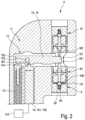
- the lever arm 16 longitudinally extends between a first end 161 and a second end 162 (see Fig. 2 ). In the embodiment shown in Figs. 1 and 2 , the first end 161 alternately acts on the inlet valve 9 or the outlet valve 10.
- the lever arm 16 is hinged at a pivot 163 and, consequently, pivotally movable between its first position and its second position.
- the pivot 163 can also be referred to as fulcrum.
- the biasing member 15 is arranged at the second end 162 of the lever arm 16.
- the force generating member 14 is located between the pivot 163 and the first end 161 of the lever arm 16.
- the distance between the first end 161 acting on the valves 9, 10 and the pivot 163 as well as the distance between the force generating member 14 and the pivot 163 defines the amplification, i.e., leverage and/or mechanical advantage, of the lever arm 16.
- a motion M1 generated by means of the force generating member 14 is amplified into an actuation motion M2 in a ratio of 1:20.
- the force generating member is located, for example, at the second end of the lever arm, while the biasing member is located, for example, between the pivot and the first end.
- the specific arrangement of the force generating member 14, the biasing member 15 and the pivot 163 with respect to each other and to the first end 161 and the second end 162 as depicted in Fig. 2 is exemplary and may be different in other embodiments.
- the lever arm is fixedly mounted and flexibly bendable between the first position and the second position.
- the pivot 163 shown in Fig. 2 is optional.
- the force generating member 14 is a piezoelectric element 141.
- the piezoelectric element 141 is, in the shown embodiment, in the form of a piezo stack 142, i.e., a longitudinally shaped piezoelectric element, while other shapes and forms are possible as well.
- the piezoelectric element 141 operates on the basis of known physical principles. In particular, the piezoelectric element 141 extends and/or expands when subjected to electrical energy. When deenergized, the piezoelectric element 141 returns into its original unexpanded/unextended state.
- control unit 143 energizing and deenergizing of the piezoelectric element 141 is controlled by means of a control unit 143.
- Said control unit 143 can be provided as an integral component of the metering assembly 4.
- the control unit 143 can be provided as a separate component connected to the metering assembly 4, in particular the piezoelectric element 141.
- the control unit 143 is schematically depicted, wherein said connection to the piezoelectric element 141 is symbolized by means of a broken line.
- the control unit is not part of the apparatus 1 but instead a separate unit external from the patient's body B and connected to the apparatus by means of a suitable wireless connection. Consequently, the control unit 143 is optional and not essential to the present invention.
- energizing the piezoelectric element 141 causes one end 144 of the piezoelectric element 141 to move and press against the lever arm 16. This causes the lever arm 16 to pivotally move around the pivot 163 - with respect to Fig. 2 - in a counter-clockwise direction, whereby its first end 161 acts on the outlet valve 10.
- the piezoelectric element 141 works against the bias of the biasing member 15.
- Deenergizing the piezoelectric element 141 causes the end 144 to move away from the lever arm 16 and, consequently, giving way to a clockwise pivotal movement of the lever arm 16 induced by the bias of the biasing member 15.
- the first end 161 consequently, moves away from the outlet valve 10 deactivating its actuations and instead actuates the inlet valve 9.
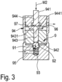
- the inlet valve 9 and the outlet valve 10 comprise a specific design which is illustrated by means of Fig. 3 and with respect to the inlet valve 9.
- the inlet valve 9 and the outlet valve 10 are identical. Hence, the following description of details of the inlet valve 9 applies, mutatis mutandis, also with respect to the outlet valve 10.
- the inlet valve 9 comprises a movable ball valve element 91, a fixed valve seat 92 and a biasing element 93.
- the biasing element 93 biases the ball valve element 91 into the valve seat 92, thereby closing the inlet valve 9 and thus causing the normally closed state of the inlet valve 9.
- the actuator 12 and more specifically the actuator member 13 in form of the lever arm 16 acts on the ball valve element 91 and against the bias of the biasing element 93.
- the actuator 12 acts indirectly on the ball valve element 91 by means of a transmitting member 94 of the inlet valve 9.
- the actuation motion M2 of the actuator 12 is transmitted onto the ball valve element 91 by means of said transmitting member 94 in order to open the inlet valve 9.
- both valves 9, 10 further comprise a valve inlet passage 95 and a valve outlet passage 96.
- the valve inlet passage 95 is fluidly connected with the inlet conduit 5 while the valve outlet passage 96 is in fluid connection with the accumulator volume 8.
- the outlet valve 10 its valve inlet passage 95 is in fluid connection with the accumulator volume 8 while its valve outlet passage 96 is in fluid connection with the outlet conduit 6.
- the ball valve element 91 and the valve seat 92 are in line with the valve inlet passage 95 and the valve outlet passage 96. Moving the ball valve element 91 away from the valve seat 92 allows an infusate flow between the valve inlet passage 95 and the valve outlet passage 96.
- the transmitting member 94 longitudinally extends between a first end 941 and a second end 942.
- the first end 941 is configured for being contacted by the actuator 12 or more specifically with respect to the shown embodiment, the first end 161 of the lever arm 16.
- the second end 942 of the transmitting member 94 is configured for contacting the ball valve element 91.
- the transmitting member 94 is axially movable by means of the lever arm 16 in order to open the valve 9.
- moving the lever arm 16 in its first position causes the first end 161 of the lever arm 16 to press onto the first end 941 of the transmitting member 94, whereby the actuation motion M2 is transmitted onto the ball valve element 91, moving the ball valve element 91 away from the valve seat 92 and thus oping the inlet valve 9.
- Moving the lever arm 16 back in its second position causes the bias of the biasing element 93 to move the ball valve element 91 back and into the valve seat 92, thereby also moving the transmitting member 94 back to its original position.
- the transmitting member 94 has a two-part design comprising a first transmitting pin 943 and a second transmitting pin 944. Said pins 943, 944 are coaxial to each other and to the ball valve element 91.
- the first transmitting pin 943 comprises the second end 942 and is located in line with the valve seat 92 and the valve outlet passage 96.
- the first transmitting pin 943 is consequently located in a fluid carrying region of the valve 9.
- the second pin 944 in contrast, is located in a "dry" region of the valve 9 which is not fluid carrying.
- the second transmitting pin 944 comprises the first end 941 of the transmitting member 94 and a contact end 9441.
- Said contact end 9441 opposes the first end 941 and contacts a complementary contact end 9431 of the first transmitting pin 943 via a fluid-tight flexible septum 97 which fluidly separates said fluid-carrying and dry regions of the inlet valve 9.
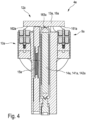
- Figs. 4 and 5 illustrate a further embodiment of a metering assembly 4a according to the invention.
- the metering assembly 4a is substantially identical to the metering assembly 4 of the embodiment according to Figs. 1 to 3 . To avoid repetition, only relevant differences of the metering assembly 4a over the metering assembly 4 will be described. If not described differently, the disclosure regarding the metering assembly 4 also applies, mutatis mutandis, with respect to the metering assembly 4a. Hence, not all features/details of the metering assembly 4a are described separately. Instead, reference is made to the description of the metering assembly 4.
- the metering assembly 4a differs in that the inlet valve 9a and the outlet valve 10a are arranged at the opposing ends 161a, 162a of the lever arm 16a.
- the inlet valve 9a is arranged at the first end 161a.
- the outlet valve 10a is arranged at the second end 162a.
- the first end 161a is configured to actuate the inlet valve 9a while the second end 162a is configured to actuate the outlet valve 10a.
- the lever arm 16a is hinged at a pivot 163a and, consequently, pivotally movable between its first position, in which the first end 161a actuates an opening of the inlet valve 9a, and its second position, in which the second end 162a actuates an opening of the outlet valve 10a.
- the pivot 163a is located substantially in the middle between the first end 161a and the second end 162a.
- the force generating member 14a acts on a contact point (without reference sign) longitudinally located between the first end 161a and the pivot 163a, thereby forming a T-shape with the lever arm 16a.
- the biasing member 15a contacts the lever arm 16a at a contact point (without reference sign) located longitudinally between the second end 162a and the pivot 163a.
Landscapes
- Health & Medical Sciences (AREA)
- Biomedical Technology (AREA)
- Hematology (AREA)
- Vascular Medicine (AREA)
- Engineering & Computer Science (AREA)
- Anesthesiology (AREA)
- Veterinary Medicine (AREA)
- Heart & Thoracic Surgery (AREA)
- Public Health (AREA)
- Life Sciences & Earth Sciences (AREA)
- Animal Behavior & Ethology (AREA)
- General Health & Medical Sciences (AREA)
- Fluid Mechanics (AREA)
- Physics & Mathematics (AREA)
- Infusion, Injection, And Reservoir Apparatuses (AREA)
Description
- This invention relates to a metering assembly according to the preamble of claim 1.
-
US patent number 5,049,141 discloses an implantable infusion apparatus comprising a metering assembly having the features of the preamble of claim 1. The prior art implantable infusion apparatus is intended for the delivery of an infusate, i.e., a medical fluid or a fluid drug, to a patient and comprises a pressurized infusate reservoir, an infusate dispensing member and said metering assembly. The infusate reservoir is filled with said infusate and pressurized at a pressure above the pressure inside the patient's body. The infusate dispensing member of the prior art apparatus is in the form of a catheter and configured to dispense infusate from the infusate reservoir to a site inside the patient's body. The metering assembly is configured to control the amount of infusate to be infused per unit of time, i.e., the drug dosage. For this purpose, the prior art metering assembly comprises an infusate accumulator with an accumulator volume and a pair of normally closed valves, i.e., an inlet valve and an outlet valve. The inlet valve controls the inlet of infusate from the reservoir into the accumulator volume. The outlet valve controls the outlet of infusate from the accumulator volume to the infusate dispensing member. In a first state, the inlet valve is open and the outlet valve is closed, thereby allowing an infusate flow from the pressurized infusate reservoir into the accumulator volume while blocking an infusate flow from the accumulator volume through the dispensing member. In a second state, the inlet valve is closed and the outlet valve is open, thereby allowing an infusate flow from the accumulator volume through the dispensing member while blocking an infusate flow from the pressurized infusate reservoir into the accumulator volume. The accumulator volume has a pressure intermediate between the pressure of the pressurized infusate reservoir and the pressure inside the patient's body. Therefore, in the second state, infusate accumulated inside the accumulator volume is "pumped" from the accumulator volume into the infusate dispensing member and thus into the patient's body. Cycling between the first and second state allows to control the infused drug dosage, wherein increasing the rate of cycling increases the infused volume per unit of time and thus the dosage of the drug. The prior art metering assembly comprises an actuator device configured for actuating the inlet valve and the outlet valve between said first and second states. The actuator device of the prior art metering assembly comprises two separate actuators for controlling the open and close cycles of the inlet valve and the outlet valve. Said separate actuators are in the form of electronically controlled solenoids, a first solenoid actuating the inlet valve and a second solenoid actuating the outlet valve. There is a potential risk that magnetic field effects, for example during a magnetic resonance imaging (MRI), cause a malfunction of the solenoids leading to an unintended opening of both the inlet valve and the outlet valve at the same time resulting in an uncontrolled drug overdose. -
US 2011/060318 A1 discloses an implantable pump for providing metered doses of a compound to an individual. The implantable pump includes a chamber for storing an individual dose of the compound, an inlet valve fluidly coupled to the chamber for controlling a flow of the compound into the chamber, and an outlet valve fluidly coupled to the chamber for controlling a flow of the compound out of the chamber and into the individual. The pump includes an inlet valve driver circuit operable for opening and closing the inlet valve, and an outlet valve driver circuit operable for opening and closing the outlet valve. A battery and a charging circuit that includes a capacitor are included in the implantable pump. The charging circuit is operatively coupled to the battery for charging of the capacitor. The charged capacitor is operable for supplying power to the valve driver circuits. -
WO 2021/067674 A1 discloses an implantable drug delivery device and a method that includes a sensor device for detecting deflection of a diaphragm at a first time from a first position within a diaphragm chamber of an accumulator of the implantable drug delivery device. A cycle count may be incremented in response to the diaphragm returning to the first position within the diaphragm chamber, each time during cyclical deflections within the diaphragm chamber. A flow rate of infusate may be determined based on a volume of the diaphragm chamber, the cycle count, and an elapsed time since the first time. Once the flow rate is determined, a processor may determine whether the flow rate of infusate is normal based on a comparison of the determined flow rate to at least one threshold flow rate. - It is an object of this invention to provide a metering assembly as mentioned at the beginning, that has improved safety while being simple and robust in design.
- This object is solved by providing the actuator device with an actuator movable between a first position and a second position for alternating actuation of the inlet valve or the outlet valve between the first state and the second state, wherein in the first position, the actuator mechanically actuates the inlet valve and does not actuate the outlet valve, and wherein in the second position, the actuator mechanically actuates the outlet valve and does not actuate the inlet valve. Due to the alternating mechanical actuation of both the inlet valve and the outlet valve by means of one and the same actuator, simultaneously actuating both valves is not possible. Consequently, opening the inlet valve and the outlet valve at the same time and a resulting uncontrolled infusate delivery is not possible. This leads to an improved safety. At the same time, using one and the same actuator for the actuation of both valves leads to a simple and robust design, allowing for an easy and inexpensive manufacture. In different embodiments, the actuator is differently movable between the first position and the second position. In one embodiment, the actuator moves linearly and/or in translation. In another embodiment, the actuator moves rotationally. In yet another embodiment, the actuator moves pivotally. Of course, a combined linear, rotational and/or pivotal motion of the actuator is also possible and envisaged. The movement between the first position and the second position can be the result of a rigid body motion of the actuator, an elastic deformation of at least a portion of the actuator or a combination of both. Both valves are normally closed, i.e., in a closed state blocking infusate flow if and when not actuated by means of the actuator. Consequently, the first position of the actuator controls the first state and the second position of the actuator controls the second state. In one embodiment, the inlet valve and the outlet valve each comprise a biasing member configured for biasing the respective valve into its closed position. In another embodiment, both valves each comprise a closing mechanism configured to keep the respective valve closed if and when not actuated. In different embodiments, the actuator actuates the valves in different ways. In one embodiment, the actuator is configured to open the valves by means of a pushing motion and/or a pushing force. In another embodiment, the actuator is configured to open the valves by means of a pulling motion and/or a pulling force. In yet another embodiment, the actuator is configured to open the valves by means of a turning motion and/or a torque. Of course, combinations thereof are possible and envisaged. The mechanical action of the actuator on the inlet valve and the outlet valve can be direct or indirect. In one embodiment, a portion of the actuator alternately directly contacts a portion of the inlet valve or a portion of the outlet valve, said contacts transmitting a force and/or motion of the actuator onto the respective valve in order to open it. In another embodiment, said alternating contact is indirect, the actuator acting on a transmitting member which in turn (directly) acts on the respective valve. The pressurized infusate reservoir and the infusate dispensing member do not form components of the metering assembly but instead of the implantable infusion apparatus. The infusate reservoir is configured to contain and pressurize the infusate by known techniques, for example by means of a two-phase fluid induced pressure. Technical details of the pressurized infusate reservoir are not essential to the present invention and therefore omitted. In a preferred embodiment, the infusate dispensing member is a catheter. However, technical details of the infusate dispensing member are not essential to the present invention and therefore omitted. The same applies, mutatis mutandis, regarding the infusate accumulator with the accumulator volume. In a preferred embodiment, the accumulator volume is formed by means of a diaphragm arranged in an accumulator chamber of the infusate accumulator, wherein said diaphragm is deflectable by means of the infusate inflow from the pressurized infusate reservoir while the valves reside in the first state. The pressure on a back side of the diaphragm can be said intermediate pressure causing the described "pumping" action of the infusate accumulator. However, other infusate accumulator designs are possible and envisaged.
- In one embodiment, the actuator comprises an actuator member alternately acting on the inlet valve or the outlet valve, and a force generating member operatively coupled with the actuator member and configured for generating a force and/or motion for moving the actuator member between the first position and the second position. In one embodiment, the actuator member is a lever arm pivotally movable and/or flexibly bendable between the first position and the second position. In another embodiment, the actuator member is a push rod or a pull rod linearly movable between the first and second position. In yet another embodiment, the actuator member is a cam member rotationally movable between the first and second position. The force generating member is configured to generate a force and/or motion for moving the actuator member between the first and second position. In one embodiment, the force generating member is configured to move the actuator member from the first position into the second position, while moving the actuator member from the second position into the first position is not possible by means of the force generating member. In another embodiment, the force generating member is configured for moving the actuator member from the second position into the first position, while a reverse positioning is not possible by means of the force generating member. In these cases, the actuator preferably comprises a biasing member operatively coupled with the actuator member which biases the actuator member into the not actively actuated position. In yet another embodiment, the force generating member is configured to move the actuator member in both positions which allows to omit said biasing member. In a preferred embodiment, the force generating member is a piezoelectric element. In other embodiments, the force generating member relies on other physical operating principles, for example a hydraulic, pneumatic, magnetic principle to generate said force and/or motion.
- In one embodiment, the actuator comprises a biasing member operatively coupled with the actuator member and biasing the actuator member against the force and/or motion of the force generating member. This enables the use of a single-direction force generating member which is configured to move the actuator member from the first position into the second position or vice versa but not alternately between both positions. Consequently, a further design simplification and cost reductions can be achieved. In one embodiment, the biasing member is a spring element, preferably in the form of a helical spring. In another embodiment, the biasing member is an elastomeric element or the like.
- In one embodiment, the actuator member is a lever arm movable between the first position and the second position by means of the force generating member, the lever arm amplifying the motion of the force generating member into an amplified actuation motion. The lever arm leverages the motion of the force generating member. This allows to employ a force generating member having a relatively small range of motion/displacement which, without leveraging, would not suffice to actuate the valves.
- Employing a small displacement/range of motion force generating member can lead to a further simplified design and reduced costs. The lever arm has a positive mechanical advantage regarding the motion of the force generating member. Preferably, said mechanical advantage is in a range between 1:5 and 1:60, preferably between 1:10 and 1:30, more preferably at least approximately 1:20. Consequently, due to the basic mechanical principles involved, the mechanical advantage on the force of the force generating member is negative.
- In one embodiment, the lever arm is hinged at a pivot and pivotally movable between the first position and the second position. The pivot, for example, is in the form of a pin, a fulcrum or the like. In this embodiment, the lever arm is at least substantially rigid, the motion of the lever arm between the first and the second position, consequently, being a rigid body motion. This embodiment allows for a further simplified and yet more robust design.
- In one embodiment, the lever arm is fixedly mounted and flexibly bendable between the first position and the second position. In this embodiment, at least a portion of the lever arm is elastic and/or pliable in order to allow a flexible bending motion between the first and the second position. This can be achieved by choosing appropriate elastic material and/or geometric properties of the lever arm. Since there is no need for a pivot and/or fulcrum, this embodiment allows for a very simple and very robust design.
- In one embodiment, the inlet valve and the outlet valve are arranged at one end of the lever arm, said end of the lever arm alternately acting on both valves. This embodiment is space saving and allows for a compact design.
- In one embodiment, the inlet valve and the outlet valve are arranged at opposing first and second ends of the lever arm, wherein the first end acts on the inlet valve and the second end acts on the outlet valve. This allows for additional degrees of freedom regarding the design of the metering assembly, in particular the arrangement of the inlet valve and the outlet valve with respect to other components. Moreover, it is possible to use different mechanical advantages for the actuation of the different valves. In this embodiment, the lever arm moves like a rocker or seesaw between the first position and the second position.
- In one embodiment, the force generating member is a piezoelectric element, preferably in the form of a piezo stack. Piezoelectric elements are often referred to as piezoelectric actuators and work on the basis of known physical principles. Energizing the piezoelectric element causes the piezoelectric element to expand and/or extend. Deenergizing causes the piezoelectric element to return to its unexpanded/unextended (original) dimensions. Using a piezo stack, which is a known form of piezoelectric element, allows for a slender design while providing a relatively large range of motion/displacement of the force generating element. The piezoelectric element is a highly useful component as it has the ability to change shape in response to voltage. When a positive voltage is applied, it expands, whereas a negative voltage causes it to shrink. The degree of expansion varies depending on both the length of the piezoelectric element and the voltage applied. This means that the longer the piezoelectric element and the higher the voltage, the greater the expansion. Moreover, the material of the piezoelectric element generates a blocking force that relies on both the voltage and the cross-section of the piezoelectric element. A larger cross-section and higher voltage result in a greater blocking force that it can generate and transmit. The present invention takes advantage of the unique characteristics of the piezoelectric element/its material. In one embodiment its expansion is used and amplified using said lever arm to reach the desired amount of movement. This ensures operation within the required force's working range, while still achieving the desired displacement.
- In one embodiment, the inlet valve and the outlet valve each comprise a movable ball valve element, a fixed valve seat and a biasing element, which biases the ball element into the valve seat, wherein the actuator at least indirectly acts on the ball valve element. This embodiment allows for a further simplified and very robust design. Preferably, the biasing element is a spring element, in particular a helical spring. The biasing element pushes the ball valve element into the valve seat, thereby biasing the respective valve into its closed position. In one embodiment, the actuator directly acts on the ball valve element for opening the respective valve. In another embodiment, said action is indirect via a transmitting member or the like.
- In one embodiment, the inlet valve and the outlet valve each comprise an axially movable transmitting member longitudinally extending between a first end and a second end, wherein the first end of the transmitting member is configured for contacting the actuator and the second end of the transmitting member is configured for contacting the ball valve element. The transmitting member is configured to transmit the force and/or motion of the force generating member onto the respective valve, in particular onto the respective ball valve element. The transmitting member can have a single-part or a multi-part design. This embodiment allows to arrange the actuator further away from the valves and with this further away from fluid carrying components/portions of the metering assembly.
- The invention further relates to an implantable infusion apparatus comprising a metering assembly according to the preceding disclosure, and further comprising a pressurized infusate reservoir and an infusate dispensing member, wherein the inlet conduit of the metering assembly is in fluid communication with the infusate reservoir, and wherein the outlet conduit of the metering assembly is in fluid communication with the infusate dispensing member.
- In the following, exemplary embodiments of the invention are described in detail with reference to the drawings. Throughout the drawings, same elements are denoted with same reference numerals. The drawings schematically show:
- Fig. 1
- an illustration of one embodiment of an implantable infusion apparatus according to the invention having one embodiment of a metering assembly according to the invention, the metering assembly being depicted in a cross-sectional view;
- Fig. 2
- the metering assembly shown in
Fig. 1 in a further sectional view with respect to a longitudinal section plane; - Fig. 3
- a cross-sectional view of a valve of the metering assembly according to
Figs. 1 and2 ; - Fig. 4
- a longitudinally sectioned view of a further embodiment of a metering device according to the invention; and
- Fig. 5
- a further longitudinally sectioned view of the metering assembly according
Fig. 4 . - Referring to
Fig. 1 , an implantable infusion apparatus 1 comprises apressurized infusate reservoir 2, an infusate dispensing member 3 and ametering assembly 4. The implantable infusion apparatus 1 is configured for the delivery of infusate F, i.e., a medical fluid or fluid drug, to a patient. In the configuration depicted inFig. 1 , the infusion apparatus 1 is implanted into the body B of the patient. - The
infusate reservoir 2 contains a pressurized volume of the infusate F to be infused. Inside theinfusate reservoir 2, the infusate F is pressurized with a reservoir pressure p1. The reservoir pressure p1 is generated by means of known techniques and can be constant or varying. Technical details of thepressurized infusate reservoir 2 are not within the focus of the present invention. A more detailed description of the specific design and function of thepressurized infusate reservoir 2 is therefore not necessary. - The infusate dispensing member 3 is configured for dispensing infusate F from the
infusate reservoir 2 to a site inside the patient's body B. The infusate dispensing member 3 is fluidly connected with theinfusate reservoir 2 via themetering assembly 4. - In the embodiment shown, the infusate dispensing member 3 is a catheter 31 having a
distal end 32 and aproximal end 33. Thedistal end 32 can also be referred to as catheter tip and is located at said site inside the body B. Theproximal end 33 is fluidly connected with themetering assembly 4. - In the embodiment shown, the
pressurized infusate reservoir 2 and themetering assembly 4 are arranged in a housing which is not depicted in detail. The housing containing theinfusate reservoir 2 and themetering assembly 4 is made of a biocompatible material and implanted into the patient's body B. In an embodiment not shown in the figures, the pressurized infusate reservoir and the metering assembly each comprise a separate housing, said housings being implanted at different locations of the patient's body. - The
metering assembly 4 comprises aninlet conduit 5, an outlet conduit 6, an infusate accumulator 7 having anaccumulator volume 8, aninlet valve 9, anoutlet valve 10 and anactuator device 11. - The
inlet conduit 5 is fluidly connected with thepressurized infusate reservoir 2. Said fluid connection is schematically depicted by means of the broken line extending between theinfusate reservoir 2 and theinlet conduit 5 as shown inFig. 1 . Theinlet conduit 5 is configured for receiving an infusate flow from thepressurized infusate reservoir 2. - The outlet conduit 6 is fluidly connected with the infusate dispensing member 3. Said fluid connection is schematically depicted by the broken line extending between the outlet conduit 6 and the fluid dispensing member 3 as shown in
Fig. 1 . The outlet conduit 6 is configured for delivering an infusate flow to the fluid dispensing member 3, i.e., the catheter 31. In the embodiment shown, the outlet conduit 6 is fluidly connected with theproximal end 33 of the fluid dispensing member 3 in form of the catheter 31. - The infusate accumulator 7 comprises the
accumulator volume 8. The infusate accumulator 7 is configured for accumulating a defined fixed volume of infusate received from theinfusate reservoir 2 and to be delivered to the infusate dispensing member 3. Said fixed volume is accumulated inside theaccumulator volume 8. Theaccumulator volume 8 is in line with theinlet conduit 5 and the outlet conduit 6. - The
inlet valve 9 is in fluid communication with theinlet conduit 5 and theaccumulator volume 8. In other words, theinlet valve 9 is in line with theinlet conduit 5 and theaccumulator volume 8. Theinlet valve 9 controls the infusate flow from theinfusate reservoir 2 into theaccumulator volume 8. - The
outlet valve 10 is in fluid communication with theaccumulator volume 8 and the outlet conduit 6. In other words, theoutlet valve 10 is in line with theaccumulator volume 8 and the outlet conduit 6. Theoutlet valve 10 controls the infusate flow from theaccumulator volume 8 into the fluid dispensing member 3. - The
inlet valve 9 and theoutlet valve 10 are both normally closed. This means that infusate flow through thevalves valves actuator device 11. - The
actuator device 11 is configured for actuating theinlet valve 9 and theoutlet valve 10 between a first state and a second state. In the first state, theinlet valve 9 is open and theoutlet valve 10 is closed. The openedinlet valve 9 allows an infusate flow from theinfusate reservoir 2 through theinlet conduit 5 into theaccumulator volume 8. Theclosed outlet valve 10 simultaneously blocks an infusate flow from theaccumulator volume 8 through the outlet conduit 6 and into the fluid dispensing member 3. In the second state, theinlet valve 9 is closed and theoutlet valve 10 is open. Theclosed inlet valve 9 blocks an infusate flow from theinfusate reservoir 2 through theinlet conduit 5 into theaccumulator volume 8. Simultaneously, the openedoutlet valve 10 allows an infusate flow from theaccumulator volume 8 through the outlet conduit 6 into the fluid dispensing member 3. - Cycling or switching between first state and the second state causes a charging and discharging of the
accumulator volume 8, i.e., a "pumping", whereby a rate of switching or cycling defines the amount of infusate F infused per unit of time and therefore the dosage of infusate F delivered to the patient. The amount of infusate F per unit of time can also be denoted as infusate rate FR. - The aforementioned "pumping" action can be described in more detail as follows:
In a first step, theinlet valve 9 is open and theoutlet valve 10 is closed, i.e., thevalves accumulator volume 8. - In a second step, the
full accumulator volume 8 is discharged through the outlet conduit 6 by actuating thevalves inlet valve 9 closed,outlet valve 10 open). - Consequently, the accumulator device 7, more specifically its
accumulator volume 8, is alternately filled and emptied by a switching action of thevalves - In the embodiment shown, the accumulator device 7 operates on the basis of known principles and comprises a design which is known at least in principle. Hence, the accumulator device 7 operates at an accumulator pressure p2 which is intermediate between the reservoir pressure p1 and a pressure p3 inside the patient's body B. The pressure p3 inside the patient's body B may be an atmospheric or cardiovascular pressure slightly above the atmospheric pressure. Said pressure setup, i.e., p1 > p2 > p3, results in the above-described pumping action.
- In the specific embodiment shown, the accumulator device 7 comprises an
accumulator chamber 71, apressure chamber 72, adiaphragm 73, aback stop surface 74 and afront stop surface 75. - It is worth stressing, that the depicted design of the accumulator device is optional and not essential to the present invention. Consequently, embodiments not shown in the figures, comprise differently designed accumulator devices.
- Now with further reference to the specific design of the accumulator device 7 of the shown embodiment, the
diaphragm 73 is arranged in theaccumulator chamber 71. Thediaphragm 73 is deflectable between a first position as depicted inFig. 1 and a second position. The second position of thediaphragm 73 is schematically illustrated with the broken line inside the accumulator chamber shown inFig. 1 . In its first position, thediaphragm 73 lays flat on thefront stop surface 75. In its second position, thediaphragm 73 is deflected from thefront stop surface 75 and pressed onto theback stop surface 74, thereby defining saidfixed accumulator volume 8 inside theaccumulator chamber 71. Thepressure chamber 72 is pressurized at the accumulator pressure p2 and in fluid communication with a back surface of thediaphragm 73 which opposes theaccumulator volume 8. It is worth mentioning, that embodiments not shown in the figures, do not comprise apressure chamber 72. - Now referring again to the above-mentioned steps of the pumping action, the
accumulator volume 8 is empty when thediaphragm 73 is in its first position. Opening theinlet valve 9 while keeping theoutlet valve 10 closed, causes the inflowing infusate to deflect thediaphragm 73 into its second position, thereby fillingaccumulator chamber 71 and/or theaccumulator volume 8 to its defined fixed volume. Then, closing theinlet valve 9 and opening theoutlet valve 10, i.e., actuating thevalves diaphragm 73 back into its first position flat against thefront stop surface 75, thereby emptying and discharging theaccumulator volume 8 through the outlet conduit 6. - Since p1 > p3, opening both
valves infusate reservoir 2 through themetering assembly 4, from there directly into the fluid dispensing member 3 and further into the patient's body B. This would lead to an uncontrolled delivery of infusate F to the patient. - In order to avoid the risk of such an uncontrolled infusate delivery, the
actuator device 11 comprises anactuator 12 which is movable between a first position and a second position for alternating actuation of theinlet valve 9 or theoutlet valve 10 between the first state and the second state, wherein in the first position, theactuator 12 actuates theinlet valve 9 and does not actuate theoutlet valve 10, and wherein in the second position, theactuator 12 actuates theoutlet valve 10 and does not actuate theinlet valve 9. - Since both
valves same actuator 12, it is not possible to simultaneously open bothvalves actuator 12. The alternating actuation of bothvalves same actuator 12 leads to an improved safety and simple design. - Referring to
Figs. 1 and2 , said first position of theactuator 12 is depicted. Since bothvalves actuator 12 controls the first state of thevalves actuator 12 controls the second state of thevalves actuator 12 to from its second position into its first position opens theinlet valve 9 and deactivates the actuation of theoutlet valve 10 causing it to close. Moving the actuator 12 from its first position into its second position deactivates the actuation of theinlet valve 9 causing it to close, while theoutlet valve 10 is actuated and thereby open. - Referring now to
Fig. 2 , theactuator 12 comprises an actuator member 13 and a force generating member 14. The actuator member 13 is configured to directly or indirectly act - by means of a force and/or motion, i.e., mechanically - on thevalves actuator 12 is optional. Hence, in embodiments not shown in the figures, the functions of force and/or motion generation and the function of acting on the valves are integrated into one and the same member. - In the embodiment shown, the
actuator 12 further comprises a biasingmember 15. The biasingmember 15 is configured for biasing theactuator member 12 against the force and/or motion of the force generating member 14. The biasingmember 15 is optional and, in particular, not needed in case the force generating member 14 is configured to move the actuator member 13 back and forth between the first position and the second position. In the embodiment shown, however, the force generating member 14 is configured to move theactuator member 12 from its first position into its second position - but not vice versa - and against the bias of the biasingmember 15. In the embodiment shown, moving the actuator member 13 from its second position into its first position solely by means of the force generating member 14 is not possible. Said motion of the actuator member 13 is instead induced by means of the biasingmember 15. Of course, other embodiments are envisaged where the force generating member is configured to move the actuator member from its second to its first position but not the other way around. - In the embodiment shown, the actuator member 13 is a lever arm 16. The lever arm 16 is movable between the first position and the second position by means of the force generating member 14, thereby amplifying the motion of the force generating member 14 into an amplified actuation motion acting on the
inlet valve 9 or, respectively, theoutlet valve 10. - The lever arm 16 longitudinally extends between a
first end 161 and a second end 162 (seeFig. 2 ). In the embodiment shown inFigs. 1 and2 , thefirst end 161 alternately acts on theinlet valve 9 or theoutlet valve 10. - In the embodiment shown, the lever arm 16 is hinged at a
pivot 163 and, consequently, pivotally movable between its first position and its second position. Thepivot 163 can also be referred to as fulcrum. - In the embodiment shown, the biasing
member 15 is arranged at thesecond end 162 of the lever arm 16. The force generating member 14 is located between thepivot 163 and thefirst end 161 of the lever arm 16. The distance between thefirst end 161 acting on thevalves pivot 163 as well as the distance between the force generating member 14 and thepivot 163 defines the amplification, i.e., leverage and/or mechanical advantage, of the lever arm 16. - In the embodiment shown, a motion M1 generated by means of the force generating member 14 is amplified into an actuation motion M2 in a ratio of 1:20.
- The described mechanical leverage principles apply, mutatis mutandis, also with respect to the bias generated by means of the biasing
member 15. - In embodiments not shown in the figures, the force generating member is located, for example, at the second end of the lever arm, while the biasing member is located, for example, between the pivot and the first end. In other words, the specific arrangement of the force generating member 14, the biasing
member 15 and thepivot 163 with respect to each other and to thefirst end 161 and thesecond end 162 as depicted inFig. 2 is exemplary and may be different in other embodiments. - Further, with reference to an embodiment not shown in the figures, the lever arm is fixedly mounted and flexibly bendable between the first position and the second position. Hence, the
pivot 163 shown inFig. 2 is optional. - In the embodiment shown, the force generating member 14 is a piezoelectric element 141. The piezoelectric element 141 is, in the shown embodiment, in the form of a piezo stack 142, i.e., a longitudinally shaped piezoelectric element, while other shapes and forms are possible as well.
- The piezoelectric element 141 operates on the basis of known physical principles. In particular, the piezoelectric element 141 extends and/or expands when subjected to electrical energy. When deenergized, the piezoelectric element 141 returns into its original unexpanded/unextended state.
- In the embodiment shown, energizing and deenergizing of the piezoelectric element 141 is controlled by means of a
control unit 143. Saidcontrol unit 143 can be provided as an integral component of themetering assembly 4. Alternatively, thecontrol unit 143 can be provided as a separate component connected to themetering assembly 4, in particular the piezoelectric element 141. InFig. 2 , thecontrol unit 143 is schematically depicted, wherein said connection to the piezoelectric element 141 is symbolized by means of a broken line. In an embodiment not shown in the figures, the control unit is not part of the apparatus 1 but instead a separate unit external from the patient's body B and connected to the apparatus by means of a suitable wireless connection. Consequently, thecontrol unit 143 is optional and not essential to the present invention. - In the embodiment shown, energizing the piezoelectric element 141 causes one end 144 of the piezoelectric element 141 to move and press against the lever arm 16. This causes the lever arm 16 to pivotally move around the pivot 163 - with respect to
Fig. 2 - in a counter-clockwise direction, whereby itsfirst end 161 acts on theoutlet valve 10. In its energized state, the piezoelectric element 141 works against the bias of the biasingmember 15. Deenergizing the piezoelectric element 141 causes the end 144 to move away from the lever arm 16 and, consequently, giving way to a clockwise pivotal movement of the lever arm 16 induced by the bias of the biasingmember 15. Thefirst end 161, consequently, moves away from theoutlet valve 10 deactivating its actuations and instead actuates theinlet valve 9. - In the embodiment shown, the
inlet valve 9 and theoutlet valve 10 comprise a specific design which is illustrated by means ofFig. 3 and with respect to theinlet valve 9. Theinlet valve 9 and theoutlet valve 10 are identical. Hence, the following description of details of theinlet valve 9 applies, mutatis mutandis, also with respect to theoutlet valve 10. - Now referring to
Fig. 3 , theinlet valve 9 comprises a movableball valve element 91, a fixedvalve seat 92 and a biasingelement 93. The biasingelement 93 biases theball valve element 91 into thevalve seat 92, thereby closing theinlet valve 9 and thus causing the normally closed state of theinlet valve 9. Theactuator 12 and more specifically the actuator member 13 in form of the lever arm 16 (not depicted inFig. 3 ) acts on theball valve element 91 and against the bias of the biasingelement 93. - In the embodiment shown, the actuator 12 acts indirectly on the
ball valve element 91 by means of a transmittingmember 94 of theinlet valve 9. The actuation motion M2 of theactuator 12 is transmitted onto theball valve element 91 by means of said transmittingmember 94 in order to open theinlet valve 9. - In the embodiment shown, both
valves valve inlet passage 95 and avalve outlet passage 96. Regarding theinlet valve 9, thevalve inlet passage 95 is fluidly connected with theinlet conduit 5 while thevalve outlet passage 96 is in fluid connection with theaccumulator volume 8. Now regarding theoutlet valve 10, itsvalve inlet passage 95 is in fluid connection with theaccumulator volume 8 while itsvalve outlet passage 96 is in fluid connection with the outlet conduit 6. - The
ball valve element 91 and thevalve seat 92 are in line with thevalve inlet passage 95 and thevalve outlet passage 96. Moving theball valve element 91 away from thevalve seat 92 allows an infusate flow between thevalve inlet passage 95 and thevalve outlet passage 96. - The transmitting
member 94 longitudinally extends between afirst end 941 and asecond end 942. Thefirst end 941 is configured for being contacted by theactuator 12 or more specifically with respect to the shown embodiment, thefirst end 161 of the lever arm 16. Thesecond end 942 of the transmittingmember 94 is configured for contacting theball valve element 91. The transmittingmember 94 is axially movable by means of the lever arm 16 in order to open thevalve 9. More specifically, moving the lever arm 16 in its first position causes thefirst end 161 of the lever arm 16 to press onto thefirst end 941 of the transmittingmember 94, whereby the actuation motion M2 is transmitted onto theball valve element 91, moving theball valve element 91 away from thevalve seat 92 and thus oping theinlet valve 9. Moving the lever arm 16 back in its second position causes the bias of the biasingelement 93 to move theball valve element 91 back and into thevalve seat 92, thereby also moving the transmittingmember 94 back to its original position. - In the embodiment shown, the transmitting
member 94 has a two-part design comprising afirst transmitting pin 943 and asecond transmitting pin 944. Said pins 943, 944 are coaxial to each other and to theball valve element 91. Thefirst transmitting pin 943 comprises thesecond end 942 and is located in line with thevalve seat 92 and thevalve outlet passage 96. Thefirst transmitting pin 943 is consequently located in a fluid carrying region of thevalve 9. Thesecond pin 944, in contrast, is located in a "dry" region of thevalve 9 which is not fluid carrying. Thesecond transmitting pin 944 comprises thefirst end 941 of the transmittingmember 94 and acontact end 9441. Saidcontact end 9441 opposes thefirst end 941 and contacts acomplementary contact end 9431 of thefirst transmitting pin 943 via a fluid-tightflexible septum 97 which fluidly separates said fluid-carrying and dry regions of theinlet valve 9. -
Figs. 4 and5 illustrate a further embodiment of ametering assembly 4a according to the invention. Themetering assembly 4a is substantially identical to themetering assembly 4 of the embodiment according toFigs. 1 to 3 . To avoid repetition, only relevant differences of themetering assembly 4a over themetering assembly 4 will be described. If not described differently, the disclosure regarding themetering assembly 4 also applies, mutatis mutandis, with respect to themetering assembly 4a. Hence, not all features/details of themetering assembly 4a are described separately. Instead, reference is made to the description of themetering assembly 4. - The
metering assembly 4a according toFigs. 4 and5 differs in that theinlet valve 9a and theoutlet valve 10a are arranged at the opposing ends 161a, 162a of thelever arm 16a. Theinlet valve 9a is arranged at thefirst end 161a. Theoutlet valve 10a is arranged at thesecond end 162a. Thefirst end 161a is configured to actuate theinlet valve 9a while thesecond end 162a is configured to actuate theoutlet valve 10a. Thelever arm 16a is hinged at apivot 163a and, consequently, pivotally movable between its first position, in which thefirst end 161a actuates an opening of theinlet valve 9a, and its second position, in which thesecond end 162a actuates an opening of theoutlet valve 10a. Thepivot 163a is located substantially in the middle between thefirst end 161a and thesecond end 162a. Theforce generating member 14a acts on a contact point (without reference sign) longitudinally located between thefirst end 161a and thepivot 163a, thereby forming a T-shape with thelever arm 16a. The biasingmember 15a contacts thelever arm 16a at a contact point (without reference sign) located longitudinally between thesecond end 162a and thepivot 163a.
Claims (12)
- A metering assembly (4, 4a) for an implantable infusion apparatus (1) comprising:an inlet conduit (5) configured for fluid connection with a pressurized infusate reservoir (2) of the infusion apparatus (1);an outlet conduit (6) configured for fluid connection with an infusate dispensing member (3) of the infusion apparatus (1);an infusate accumulator (7, 7a) having an accumulator volume (8);an inlet valve (9, 9a) in fluid communication with the inlet conduit (5) and the accumulator volume (8);an outlet valve (10, 10a) in fluid communication with the accumulator volume (8) and the outlet conduit (6);wherein the inlet valve (9, 9a) and the outlet valve (10, 10a) are both normally closed; andan actuator device (11) configured for actuating the inlet valve (9, 9a) and the outlet valve (10, 10a) between a first state and a second state,wherein in the first state, the inlet valve (9, 9a) is open and the outlet valve (10, 10a) is closed, thereby allowing an infusate flow through the inlet conduit (5) into the accumulator volume (8) while blocking an infusate flow from the accumulator volume (8) through the outlet conduit (6), andwherein in the second state, the inlet valve (9, 9a) is closed and the outlet valve (10, 10a) is open, thereby allowing an infusate flow from the accumulator volume (8) through the outlet conduit (6) while blocking an infusate flow through the inlet conduit (5) into the accumulator volume (8);characterized in thatthe actuator device (11) comprises an actuator (12, 12a) movable between a first position and a second position for alternating actuation of the inlet valve (9, 9a) and the outlet valve (10, 10a) between the first state and the second state,wherein in the first position, the actuator (12, 12a) mechanically actuates the inlet valve (9, 9a) and does not actuate the outlet valve (10, 10a), andwherein in the second position, the actuator (12, 12a) mechanically actuates the outlet valve (10, 10a) and does not actuate the inlet valve (9, 9a).
- The metering assembly (4, 4a) of claim 1, wherein the actuator (12, 12a) comprises an actuator member (13, 13a) alternately acting on the inlet valve (9, 9a) and
the outlet valve (10, 10a), and a force generating member (14, 14a) operatively coupled with the actuator member (13, 13a) and configured for generating a force and/or motion for moving the actuator member (13, 13a) between the first position and the second position. - The metering assembly (4, 4a) of claim 2, wherein the actuator (12, 12a) comprises a biasing member (15, 15a) operatively coupled with the actuator member (13, 13a) and biasing the actuator member (13, 13a) against the force and/or motion of the force generating member (14, 14a).
- The metering assembly (4, 4a) of claim 2 or 3, wherein the actuator member (13, 13a) is a lever arm (16, 16a) movable between the first position and the second position by means of the force generating member (14, 14a), the lever arm (16, 16a) amplifying the motion of the force generating member (14, 14a) into an amplified actuation motion.
- The metering assembly (4, 4a) of claim 4, wherein the lever arm (16, 16a) is hinged at a pivot (163, 163a) and pivotally movable between the first position and the second position.
- The metering assembly of claim 4, wherein the lever arm is fixedly mounted and flexibly bendable between the first position and the second position.
- The metering assembly (4, 4a) according to one of the claims 4 to 6, wherein the inlet valve (9) and the outlet valve (10) are arranged at one end (161) of the lever arm (16), said end (161) of the lever arm (16) alternately acting on both valves (9, 10).
- The metering assembly (4a) according to any of claims 4 to 6, wherein the inlet valve (9a) and the outlet valve (10a) are arranged at opposing first and second ends (161a, 162a) of the lever arm (16a), wherein the first end (161a) acts on the inlet valve (9a) and the second end (162a) acts on the outlet valve (10a).
- The metering assembly (4, 4a) according to any of claims 2 to 8, wherein the force generating member (14, 14a) is a piezoelectric element (141, 141a), preferably in the form of a piezo stack (142, 142a).
- The metering assembly (4, 4a) according to any of the preceding claims, wherein the inlet valve (9, 9a) and the outlet valve (10, 10a) each comprise a movable ball valve element (91), a fixed valve seat (92) and a biasing element (93), which biases the ball valve element (91) into the valve seat (92), wherein the actuator (12, 12a) at least indirectly acts on the ball valve element (91).
- The metering assembly (4, 4a) according to claim 10, wherein the inlet valve (9, 9a) and the outlet valve (10, 10a) each comprise an axially movable transmitting member (94) longitudinally extending between a first end (941) and a second end (942), wherein the first end (941) of the transmitting member (94) is configured for contacting the actuator (12, 12a) and the second end (942) of the transmitting member (94) is configured for contacting the ball valve element (91).
- An implantable infusion apparatus (1) for the delivery of infusate (F) to a patient comprising a metering assembly (4, 4a) according to any of the preceding claims, and further comprising a pressurized infusate reservoir (2) and an infusate dispensing member (3), wherein the inlet conduit (5) of the metering assembly (4, 4a) is in fluid communication with the infusate reservoir (2), and wherein the outlet conduit (6) of the metering assembly (4, 4a) is in fluid communication with the infusate dispensing member (3).
Priority Applications (6)
| Application Number | Priority Date | Filing Date | Title |
|---|---|---|---|
| ES23160324T ES3015365T3 (en) | 2023-03-07 | 2023-03-07 | Metering assembly for an implantable infusion apparatus and implantable infusion apparatus with such a metering assembly |
| EP23160324.2A EP4427769B1 (en) | 2023-03-07 | 2023-03-07 | Metering assembly for an implantable infusion apparatus and implantable infusion apparatus with such a metering assembly |
| PL23160324.2T PL4427769T3 (en) | 2023-03-07 | 2023-03-07 | Metering assembly for an implantable infusion apparatus and implantable infusion apparatus with such a metering assembly |
| EP24707856.1A EP4676567A1 (en) | 2023-03-07 | 2024-03-04 | Metering assembly for an implantable infusion apparatus and implantable infusion apparatus with such a metering assembly |
| PCT/EP2024/055579 WO2024184304A1 (en) | 2023-03-07 | 2024-03-04 | Metering assembly for an implantable infusion apparatus and implantable infusion apparatus with such a metering assembly |
| CN202480007844.0A CN120569232A (en) | 2023-03-07 | 2024-03-04 | Metering assembly for an implantable infusion device and implantable infusion device having such a metering assembly |
Applications Claiming Priority (1)
| Application Number | Priority Date | Filing Date | Title |
|---|---|---|---|
| EP23160324.2A EP4427769B1 (en) | 2023-03-07 | 2023-03-07 | Metering assembly for an implantable infusion apparatus and implantable infusion apparatus with such a metering assembly |
Publications (3)
| Publication Number | Publication Date |
|---|---|
| EP4427769A1 EP4427769A1 (en) | 2024-09-11 |
| EP4427769C0 EP4427769C0 (en) | 2025-03-05 |
| EP4427769B1 true EP4427769B1 (en) | 2025-03-05 |
Family
ID=85510841
Family Applications (2)
| Application Number | Title | Priority Date | Filing Date |
|---|---|---|---|
| EP23160324.2A Active EP4427769B1 (en) | 2023-03-07 | 2023-03-07 | Metering assembly for an implantable infusion apparatus and implantable infusion apparatus with such a metering assembly |
| EP24707856.1A Pending EP4676567A1 (en) | 2023-03-07 | 2024-03-04 | Metering assembly for an implantable infusion apparatus and implantable infusion apparatus with such a metering assembly |
Family Applications After (1)
| Application Number | Title | Priority Date | Filing Date |
|---|---|---|---|
| EP24707856.1A Pending EP4676567A1 (en) | 2023-03-07 | 2024-03-04 | Metering assembly for an implantable infusion apparatus and implantable infusion apparatus with such a metering assembly |
Country Status (5)
| Country | Link |
|---|---|
| EP (2) | EP4427769B1 (en) |
| CN (1) | CN120569232A (en) |
| ES (1) | ES3015365T3 (en) |
| PL (1) | PL4427769T3 (en) |
| WO (1) | WO2024184304A1 (en) |
Family Cites Families (3)
| Publication number | Priority date | Publication date | Assignee | Title |
|---|---|---|---|---|
| US5049141A (en) | 1990-04-25 | 1991-09-17 | Infusaid, Inc. | Programmable valve pump |
| US9125982B2 (en) * | 2009-09-09 | 2015-09-08 | Flowonix Medical Incorporated | Methods and systems for providing metered doses of a compound to an individual |
| WO2021067674A1 (en) * | 2019-10-04 | 2021-04-08 | Flowonix Medical Incorporated | Implantable drug delivery device with infusate measuring capabilities |
-
2023
- 2023-03-07 EP EP23160324.2A patent/EP4427769B1/en active Active
- 2023-03-07 PL PL23160324.2T patent/PL4427769T3/en unknown
- 2023-03-07 ES ES23160324T patent/ES3015365T3/en active Active
-
2024
- 2024-03-04 WO PCT/EP2024/055579 patent/WO2024184304A1/en not_active Ceased
- 2024-03-04 EP EP24707856.1A patent/EP4676567A1/en active Pending
- 2024-03-04 CN CN202480007844.0A patent/CN120569232A/en active Pending
Also Published As
| Publication number | Publication date |
|---|---|
| EP4427769C0 (en) | 2025-03-05 |
| PL4427769T3 (en) | 2025-06-23 |
| ES3015365T3 (en) | 2025-05-05 |
| CN120569232A (en) | 2025-08-29 |
| WO2024184304A1 (en) | 2024-09-12 |
| EP4676567A1 (en) | 2026-01-14 |
| EP4427769A1 (en) | 2024-09-11 |
Similar Documents
| Publication | Publication Date | Title |
|---|---|---|
| JP5461408B2 (en) | Disposable infusion device with double valve system | |
| CA1134232A (en) | Implantable infusion apparatus and method | |
| EP0600948B1 (en) | Metering device for implantable delivery system | |
| WO1997007840A1 (en) | Implantable drug delivery apparatus | |
| AU2017376556B2 (en) | Ambulatory infusion device | |
| WO2006108775A2 (en) | Pump assembly with active and passive valve | |
| EP3400043A1 (en) | Fluid delivery system | |
| US6629954B1 (en) | Drug delivery pump with isolated hydraulic metering | |
| US11071819B2 (en) | Valve drive unit with shape memory alloy actuator | |
| AU2017294448B2 (en) | Infusion device drive unit with blocking device | |
| WO2012145343A2 (en) | Drug delivery device with compressible fluid chambers | |
| EP2307076B1 (en) | Mri compatible programmable valve pump | |
| EP1048309A2 (en) | Overfill protection systems for implantable drug delivery devices | |
| KR102250698B1 (en) | Method and device to inject medicine | |
| EP3194776B1 (en) | Dual latching microvalves | |
| EP4427769A1 (en) | Metering assembly for an implantable infusion apparatus and implantable infusion apparatus with such a metering assembly | |
| JP2018526129A (en) | Dosing unit with low radial sealing during storage | |
| US20090281494A1 (en) | Heat Sterilizable Ambulatory Infusion Devices | |
| JP5474801B2 (en) | Disposable infusion device that can lock out reuse | |
| EP4534122A1 (en) | Medical fluid dosing device | |
| WO2009069045A1 (en) | Implantable therapeutic substance delivery device | |
| WO2006037330A1 (en) | A pumping system and a method for controlling a fluid flow in a pumping system | |
| HK1234124A1 (en) | Dual latching microvalves |
Legal Events
| Date | Code | Title | Description |
|---|---|---|---|
| PUAI | Public reference made under article 153(3) epc to a published international application that has entered the european phase |
Free format text: ORIGINAL CODE: 0009012 |
|
| STAA | Information on the status of an ep patent application or granted ep patent |
Free format text: STATUS: REQUEST FOR EXAMINATION WAS MADE |
|
| 17P | Request for examination filed |
Effective date: 20230912 |
|
| AK | Designated contracting states |
Kind code of ref document: A1 Designated state(s): AL AT BE BG CH CY CZ DE DK EE ES FI FR GB GR HR HU IE IS IT LI LT LU LV MC ME MK MT NL NO PL PT RO RS SE SI SK SM TR |
|
| GRAP | Despatch of communication of intention to grant a patent |
Free format text: ORIGINAL CODE: EPIDOSNIGR1 |
|
| STAA | Information on the status of an ep patent application or granted ep patent |
Free format text: STATUS: GRANT OF PATENT IS INTENDED |
|
| INTG | Intention to grant announced |
Effective date: 20241016 |
|
| GRAS | Grant fee paid |
Free format text: ORIGINAL CODE: EPIDOSNIGR3 |
|
| GRAA | (expected) grant |
Free format text: ORIGINAL CODE: 0009210 |
|
| STAA | Information on the status of an ep patent application or granted ep patent |
Free format text: STATUS: THE PATENT HAS BEEN GRANTED |
|
| AK | Designated contracting states |
Kind code of ref document: B1 Designated state(s): AL AT BE BG CH CY CZ DE DK EE ES FI FR GB GR HR HU IE IS IT LI LT LU LV MC ME MK MT NL NO PL PT RO RS SE SI SK SM TR |
|
| REG | Reference to a national code |
Ref country code: GB Ref legal event code: FG4D |
|
| REG | Reference to a national code |
Ref country code: CH Ref legal event code: EP |
|
| REG | Reference to a national code |
Ref country code: DE Ref legal event code: R096 Ref document number: 602023002256 Country of ref document: DE |
|
| REG | Reference to a national code |
Ref country code: IE Ref legal event code: FG4D |
|
| PGFP | Annual fee paid to national office [announced via postgrant information from national office to epo] |
Ref country code: AT Payment date: 20250417 Year of fee payment: 3 |
|
| U01 | Request for unitary effect filed |
Effective date: 20250401 |
|
| U07 | Unitary effect registered |
Designated state(s): AT BE BG DE DK EE FI FR IT LT LU LV MT NL PT RO SE SI Effective date: 20250407 |
|
| PG25 | Lapsed in a contracting state [announced via postgrant information from national office to epo] |
Ref country code: RS Free format text: LAPSE BECAUSE OF FAILURE TO SUBMIT A TRANSLATION OF THE DESCRIPTION OR TO PAY THE FEE WITHIN THE PRESCRIBED TIME-LIMIT Effective date: 20250605 |
|
| PGFP | Annual fee paid to national office [announced via postgrant information from national office to epo] |
Ref country code: ES Payment date: 20250527 Year of fee payment: 3 |
|
| PG25 | Lapsed in a contracting state [announced via postgrant information from national office to epo] |
Ref country code: NO Free format text: LAPSE BECAUSE OF FAILURE TO SUBMIT A TRANSLATION OF THE DESCRIPTION OR TO PAY THE FEE WITHIN THE PRESCRIBED TIME-LIMIT Effective date: 20250605 |
|
| PG25 | Lapsed in a contracting state [announced via postgrant information from national office to epo] |
Ref country code: HR Free format text: LAPSE BECAUSE OF FAILURE TO SUBMIT A TRANSLATION OF THE DESCRIPTION OR TO PAY THE FEE WITHIN THE PRESCRIBED TIME-LIMIT Effective date: 20250305 |
|
| PG25 | Lapsed in a contracting state [announced via postgrant information from national office to epo] |
Ref country code: GR Free format text: LAPSE BECAUSE OF FAILURE TO SUBMIT A TRANSLATION OF THE DESCRIPTION OR TO PAY THE FEE WITHIN THE PRESCRIBED TIME-LIMIT Effective date: 20250606 |
|
| U20 | Renewal fee for the european patent with unitary effect paid |
Year of fee payment: 3 Effective date: 20250630 |
|
| PG25 | Lapsed in a contracting state [announced via postgrant information from national office to epo] |
Ref country code: SM Free format text: LAPSE BECAUSE OF FAILURE TO SUBMIT A TRANSLATION OF THE DESCRIPTION OR TO PAY THE FEE WITHIN THE PRESCRIBED TIME-LIMIT Effective date: 20250305 |
|
| PG25 | Lapsed in a contracting state [announced via postgrant information from national office to epo] |
Ref country code: CZ Free format text: LAPSE BECAUSE OF FAILURE TO SUBMIT A TRANSLATION OF THE DESCRIPTION OR TO PAY THE FEE WITHIN THE PRESCRIBED TIME-LIMIT Effective date: 20250305 |
|
| PG25 | Lapsed in a contracting state [announced via postgrant information from national office to epo] |
Ref country code: SK Free format text: LAPSE BECAUSE OF FAILURE TO SUBMIT A TRANSLATION OF THE DESCRIPTION OR TO PAY THE FEE WITHIN THE PRESCRIBED TIME-LIMIT Effective date: 20250305 |
|
| PG25 | Lapsed in a contracting state [announced via postgrant information from national office to epo] |
Ref country code: IS Free format text: LAPSE BECAUSE OF FAILURE TO SUBMIT A TRANSLATION OF THE DESCRIPTION OR TO PAY THE FEE WITHIN THE PRESCRIBED TIME-LIMIT Effective date: 20250705 |
|
| PG25 | Lapsed in a contracting state [announced via postgrant information from national office to epo] |
Ref country code: MC Free format text: LAPSE BECAUSE OF FAILURE TO SUBMIT A TRANSLATION OF THE DESCRIPTION OR TO PAY THE FEE WITHIN THE PRESCRIBED TIME-LIMIT Effective date: 20250305 |
|
| PLBE | No opposition filed within time limit |
Free format text: ORIGINAL CODE: 0009261 |
|
| STAA | Information on the status of an ep patent application or granted ep patent |
Free format text: STATUS: NO OPPOSITION FILED WITHIN TIME LIMIT |
|
| REG | Reference to a national code |
Ref country code: CH Ref legal event code: L10 Free format text: ST27 STATUS EVENT CODE: U-0-0-L10-L00 (AS PROVIDED BY THE NATIONAL OFFICE) Effective date: 20260114 |
|
| 26N | No opposition filed |
Effective date: 20251208 |
|
| PGFP | Annual fee paid to national office [announced via postgrant information from national office to epo] |
Ref country code: IE Payment date: 20260323 Year of fee payment: 4 |
|
| PGFP | Annual fee paid to national office [announced via postgrant information from national office to epo] |
Ref country code: PL Payment date: 20260227 Year of fee payment: 4 |
|
| U20 | Renewal fee for the european patent with unitary effect paid |
Year of fee payment: 4 Effective date: 20260327 |