EP4427635A1 - Furniture system and furniture assembly thereof - Google Patents
Furniture system and furniture assembly thereof Download PDFInfo
- Publication number
- EP4427635A1 EP4427635A1 EP23198512.8A EP23198512A EP4427635A1 EP 4427635 A1 EP4427635 A1 EP 4427635A1 EP 23198512 A EP23198512 A EP 23198512A EP 4427635 A1 EP4427635 A1 EP 4427635A1
- Authority
- EP
- European Patent Office
- Prior art keywords
- panel
- fitting member
- connecting member
- auxiliary device
- furniture
- Prior art date
- Legal status (The legal status is an assumption and is not a legal conclusion. Google has not performed a legal analysis and makes no representation as to the accuracy of the status listed.)
- Granted
Links
Images



Classifications
-
- A—HUMAN NECESSITIES
- A47—FURNITURE; DOMESTIC ARTICLES OR APPLIANCES; COFFEE MILLS; SPICE MILLS; SUCTION CLEANERS IN GENERAL
- A47B—TABLES; DESKS; OFFICE FURNITURE; CABINETS; DRAWERS; GENERAL DETAILS OF FURNITURE
- A47B88/00—Drawers for tables, cabinets or like furniture; Guides for drawers
- A47B88/90—Constructional details of drawers
- A47B88/944—Drawers characterised by the front panel
-
- A—HUMAN NECESSITIES
- A47—FURNITURE; DOMESTIC ARTICLES OR APPLIANCES; COFFEE MILLS; SPICE MILLS; SUCTION CLEANERS IN GENERAL
- A47B—TABLES; DESKS; OFFICE FURNITURE; CABINETS; DRAWERS; GENERAL DETAILS OF FURNITURE
- A47B88/00—Drawers for tables, cabinets or like furniture; Guides for drawers
- A47B88/90—Constructional details of drawers
- A47B88/944—Drawers characterised by the front panel
- A47B88/95—Drawers characterised by the front panel characterised by connection means for the front panel
-
- A—HUMAN NECESSITIES
- A47—FURNITURE; DOMESTIC ARTICLES OR APPLIANCES; COFFEE MILLS; SPICE MILLS; SUCTION CLEANERS IN GENERAL
- A47B—TABLES; DESKS; OFFICE FURNITURE; CABINETS; DRAWERS; GENERAL DETAILS OF FURNITURE
- A47B88/00—Drawers for tables, cabinets or like furniture; Guides for drawers
- A47B88/90—Constructional details of drawers
- A47B88/944—Drawers characterised by the front panel
- A47B88/95—Drawers characterised by the front panel characterised by connection means for the front panel
- A47B2088/951—Drawers characterised by the front panel characterised by connection means for the front panel having male and female interlocking parts
-
- A—HUMAN NECESSITIES
- A47—FURNITURE; DOMESTIC ARTICLES OR APPLIANCES; COFFEE MILLS; SPICE MILLS; SUCTION CLEANERS IN GENERAL
- A47B—TABLES; DESKS; OFFICE FURNITURE; CABINETS; DRAWERS; GENERAL DETAILS OF FURNITURE
- A47B88/00—Drawers for tables, cabinets or like furniture; Guides for drawers
- A47B88/90—Constructional details of drawers
- A47B88/944—Drawers characterised by the front panel
- A47B88/95—Drawers characterised by the front panel characterised by connection means for the front panel
- A47B2088/954—Drawers characterised by the front panel characterised by connection means for the front panel fastening the front panel by a sprung bolt, latch or lock-bolt
Definitions
- the present invention is related to a furniture system and its furniture assembly.
- Patent number WO 2009/111807 discloses a drawer.
- a front panel of the drawer is arranged with a drawer bar comprising a longitudinal arm and two shorter arms extending downwards at right angles.
- Each of two ends of the drawer bar is provided with a first wall element.
- Two claw elements are respectively provided on the first wall elements.
- the claw element is configured to lock a locking element in a form of a planar clamping arm. Thereby, the shorter arms can be clamped between a rear surface of the first wall element and the locking element.
- the present invention aims at providing a furniture system and its furniture assembly having at least one auxiliary device to be installed according to user's requirements.
- the claimed furniture assembly comprises a first panel, a connecting member and an auxiliary device.
- the first panel has a first side and a second side.
- the connecting member is arranged adjacent to one of the first side and the second side of the first panel.
- the connecting member comprises a first part and a second part.
- the first part is configured to be connected to the first panel.
- the auxiliary device is configured to be mounted to the second part of the connecting member, in order to increase a height of the furniture assembly above the first panel.
- the claimed furniture system comprises a bottom plate, a first side wall, a second side wall, a first panel, a second panel, a connecting member and an auxiliary device.
- the first side wall and a second side wall are arranged at left and right sides of the bottom plate respectively.
- the first panel and a second panel are arranged at front and rear sides of the bottom plate respectively.
- the first panel has a first side and a second side.
- the connecting member is arranged adjacent to one of the first side and the second side of the first panel.
- the connecting member comprises a first part and a second part.
- the first part is configured to be connected to the first panel.
- the auxiliary device is configured to be detachably mounted to the second part of the connecting member.
- a furniture system 20 includes a first side wall 22, a second side wall 24, a bottom plate 26, a first panel 28 and a second panel 30 according to an embodiment of the present invention.
- the furniture system 20 is a drawer, but the present invention is not limited thereto.
- the first side wall 22 and the second side wall 24 are arranged at a left side and a right side of the bottom plate 26 respectively.
- the left and right sides are only for illustration to facilitate understanding of relative positions, that is, the left and right sides are interchangeable, and are not intended to limit the specific positions.
- the first panel 28 and the second panel 30 are arranged at a front side and a rear side of the bottom plate 26 respectively.
- the first panel 28 is a front panel
- the second panel 30 is a rear panel (or back panel), but the present invention is not limited thereto.
- the first side wall 22, the second side wall 24, the bottom plate 26, the first panel 28 and the second panel 30 together define an accommodating space for accommodating objects.
- the X-axis is a length direction of the furniture system 20
- the Y-axis is a width direction of the furniture system 20
- the Z-axis is a height direction of the furniture system 20.
- the length direction, the width direction and the height direction are perpendicular to each other.
- left and right sides of the furniture system 20 have substantially identical structural arrangement.
- the left side and the right side of the furniture system 20 can be respectively arranged with a first elevated member 32 and a second elevated member 34 to increase heights of the left and right sides of the furniture system 20, so as to match heights of the first panel 28 and the second panel 30.
- the first panel 28 can be mounted to a first corresponding part 38 of the first side wall 22 through a first mounting member 36, and/or the first panel 28 can be mounted to a second corresponding part 42 of the second side wall 24 through a second mounting member 40.
- first mounting member 36 a first mounting member
- second mounting member 40 a second mounting member
- the first elevated member 32 and the second elevated member 34 are omitted in FIG. 4 .
- the first panel 28 has a first side S1 and a second side S2 opposite to the first side S1.
- the furniture system 20 further comprises a first connecting member 44 arranged adjacent to the first side S1 of the first panel 28.
- the first connecting member 44 comprises a first part 46 and a second part 48.
- the first part 46 of the first connecting member 44 is configured to be connected to the first side S1 of the first panel 28.
- the first part 46 of the first connecting member 44 is connected (such as fixed) to the first side S1 of the first panel 28 through at least one fastening member 50 (as shown in FIG. 4 ) .
- the furniture system 20 further comprises a second connecting member 52 arranged adjacent to the second side S2 of the first panel 28.
- the second connecting member 52 comprises a first part (not shown in FIG. 4 due to viewing angle) and a second part 56.
- the first part of the second connecting member 52 is configured to be connected to the second side S2 of the first panel 28.
- the furniture system 20 further comprises an auxiliary device 58 configured to be mounted to the second part 48 of the first connecting member 44 and/or the second part 56 of the second connecting member 52.
- the auxiliary device 58 is configured to be mounted to the second part 48 of the first connecting member 44 and the second part 56 of the second connecting member 52.
- the first panel 28, the first connecting member 44 and the auxiliary device 58 together form a furniture assembly.
- the auxiliary device 58 is configured to increase a height of the furniture assembly above the first panel 28.
- the auxiliary device 58 is detachably mounted to the second part 48 of the first connecting member 44 and/or the second part 56 of the second connecting member 52.
- the first panel 28 comprises a bottom part 60 and a top part 62, and a first predetermined height H1 is defined between the top part 62 and the bottom part 60 of the first panel 28.
- a second predetermined height H2 is defined between a top part 64 of the auxiliary device 58 and the bottom part 60 of the first panel 28 (as shown in FIG. 5 ) , and the second predetermined height H2 is higher than the first predetermined height H1.
- the second part 48 of the first connecting member 44 is extended from the first part 46.
- the second part 48 of the first connecting member 44 is substantially perpendicularly connected to the first part 46, and the second part 48 of the first connecting 44 is extended beyond the top part 62 of the first panel 28 by a predetermined distance K (as shown in FIG. 4 ) .
- the second connecting member 52 has substantially identical structural configuration as the first connecting member 44, for simplification, no further illustration is provided.
- the auxiliary device 58 comprises a first fitting member 66, a second fitting member 68 and an extension member 70 arranged between the first fitting member 66 and the second fitting member 68.
- the extension member 70 is connected between the first fitting member 66 and the second fitting member 68.
- the auxiliary device 58 is configured to be mounted to the second part 48 of the first connecting member 44 through the first fitting member 66.
- the first fitting member 66 is configured to sleeve the second part 48 of the first connecting member 44 (as shown in FIG. 4 and FIG. 5 ).
- one of the first fitting member 66 and the second part 48 of the first connecting member 44 is formed with a mounting space 72 (such as a groove) , and the other one of the first fitting member 66 and the second part 48 of the first connecting member 44 is configured to be inserted into the mounting space 72 (as shown in FIG. 5 ), such that the first fitting member 66 and the second part 48 of the first connecting member 44 can be connected to each other.
- the second fitting member 68 is configured to sleeve the second part 56 of the second connecting member 52, such that the second fitting member 68 and the second part 56 of the second connecting member 52 can be connected to each other.
- the second fitting member 68 and the second part 56 of the second connecting member 52 can be connected to each other.
- the furniture system 20 further comprises a first fixing member 71 configured to fixedly connect the first fitting member 66 with the first connecting member 44 to each other.
- the furniture system 20 further comprises a second fixing member 73 configured to fixedly connect the second fitting member 68 with the second connecting member 52.
- the first fixing member 71 is configured to be mounted to a first corresponding feature 75 of the first elevated member 32
- the second fixing member 73 is configured to be mounted to a second corresponding feature 77 of the second elevated member 34 (please refer to FIG. 2 and FIG. 3 ).
- the first panel 28 comprises a predetermined portion 76.
- At least one of the first fitting member 66 and the second fitting member 68 is arranged with a hook configured to engage with the predetermined portion 76 of the first panel 28.
- the first fitting member 66 is arranged with a first hook 78
- the second fitting member 68 is arranged with a second hook 80.
- the first hook 78 and the second hook 80 are elastic.
- the first hook 78 and the second hook 80 are made of plastic; in other alternative embodiment, the first hook 78 and the second hook 80 are made of metal, but the present invention is not limited thereto.
- the extension member 70 is a rod, and the extension member 70, the first fitting member 66, the second fitting member 68, and the top part 62 of the first panel 28 together define a predetermined space M (as shown in FIG. 5 and FIG. 6 ).
- the furniture system 20 further comprises a first side cover 82, and the first fitting member 66 comprises a first side part 84.
- the first side cover 82 is configured to cover the first side part 84 of the first fitting member 66 and the first side S1 of the first panel 28.
- the furniture system 20 further comprises a second side cover 86, and the second fitting member 68 comprises a second side part 88.
- the second side cover 86 is configured to cover the second side part 88 of the second fitting member 68 and the second side S2 of the first panel 28.
- one of the first side cover 82 and the first side part 84 of the first fitting member 66 has at least one first connecting feature 90, such as a protrusion or an auxiliary hook, configured to connect the other one of the first side cover 82 and the first side part 84 of the first fitting member 66, such that the first side cover 82 and the first side part 84 of the first fitting member 66 are pressed against each other or buckled together.
- first connecting feature 90 such as a protrusion or an auxiliary hook
- one of the second side cover 86 and the second side part 88 of the second fitting member 68 has at least one second connecting feature 92, such as a protrusion or an auxiliary hook, configured to connect the other one of the second side cover 86 and the second side part 88 of the second fitting member 68, such that the second side cover 86 and the second side part 88 of the second fitting member 68 are pressed against each other or buckled together.
- second connecting feature 92 such as a protrusion or an auxiliary hook
- a user can put his hand into the predetermined space M, and hold the auxiliary device 58 (the extension member 70 of the auxiliary device 58) to apply a force F to open the furniture system 20 relative to a cabinet (not shown in figures) along a predetermined direction (such as an opening direction).
- a predetermined direction such as an opening direction
- the auxiliary device 58 Through engaging the first hook 78 of the first fitting member 66 (and/or the second hook 80 of the second fitting member 68) with the first panel 28 (the predetermined position 76 of the first panel 28), the auxiliary device 58 (with the second part 48 of the first connecting member 44 and/or the second part 56 of the second connecting member 52) can be prevented from being tilted or deformed relative to the first panel 28 due to unexpected movement of the auxiliary device 58 in order to improve structural strength and reliability of the auxiliary device 58.
- the extension member 70 of the auxiliary device 58 has a first side end 94 and a second side end 96 opposite to the first side end 94.
- the first fitting member 66 is configured to be detachably mounted to the first side end 94.
- the second fitting member 68 is configured to be detachably mounted to the second side end 96.
- the first side end 94 of the extension member 70 is formed with a first accommodating space configured to mount a first extension part 98 of the first fitting member 66
- the second side end 96 of the extension member 70 is formed with a second accommodating space configured to mount a second extension part 100 of the second fitting member 68.
- the auxiliary device 58 can meet diverse mounting requirements of the market.
- the extension member 70, the first fitting member 66 and the second fitting member 68 of the auxiliary device 58 can also be integrated together, but the present invention is not limited thereto.
- the furniture system and the furniture assembly according to the embodiments of the present invention have the following technical features:
Landscapes
- Furniture Connections (AREA)
- Combinations Of Kitchen Furniture (AREA)
- Drawers Of Furniture (AREA)
Abstract
Description
- The present invention is related to a furniture system and its furniture assembly.
- Patent number
WO 2009/111807 discloses a drawer. A front panel of the drawer is arranged with a drawer bar comprising a longitudinal arm and two shorter arms extending downwards at right angles. Each of two ends of the drawer bar is provided with a first wall element. Two claw elements are respectively provided on the first wall elements. The claw element is configured to lock a locking element in a form of a planar clamping arm. Thereby, the shorter arms can be clamped between a rear surface of the first wall element and the locking element. - However, in order to meet diverse requirements of the market, it is important to develop various products.
- This in mind, the present invention aims at providing a furniture system and its furniture assembly having at least one auxiliary device to be installed according to user's requirements.
- This is achieved by a furniture assembly according to claim 1 and a furniture system according to claim 13. The dependent claims pertain to corresponding further developments and improvements.
- As will be seen more clearly from the detailed description following below, the claimed furniture assembly comprises a first panel, a connecting member and an auxiliary device. The first panel has a first side and a second side. The connecting member is arranged adjacent to one of the first side and the second side of the first panel. The connecting member comprises a first part and a second part. The first part is configured to be connected to the first panel. The auxiliary device is configured to be mounted to the second part of the connecting member, in order to increase a height of the furniture assembly above the first panel.
- As will be seen more clearly from the detailed description following below, the claimed furniture system comprises a bottom plate, a first side wall, a second side wall, a first panel, a second panel, a connecting member and an auxiliary device. The first side wall and a second side wall are arranged at left and right sides of the bottom plate respectively. The first panel and a second panel are arranged at front and rear sides of the bottom plate respectively. The first panel has a first side and a second side. The connecting member is arranged adjacent to one of the first side and the second side of the first panel. The connecting member comprises a first part and a second part. The first part is configured to be connected to the first panel. The auxiliary device is configured to be detachably mounted to the second part of the connecting member.
- In the following, the invention is further illustrated by way of example, taking reference to the accompanying drawings thereof:
-
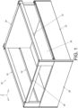
FIG. 1 is a diagram showing a furniture system according to an embodiment of the present invention; -
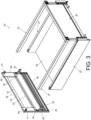
FIG. 2 is an exploded view of the furniture system from a first viewing angle according to the embodiment of the present invention; -
FIG. 3 is an exploded view of the furniture system from a second viewing angle according to the embodiment of the present invention; -
FIG. 4 is an exploded view of a furniture assembly according to the embodiment of the present invention; -
FIG. 5 is a diagram showing an auxiliary device of the furniture assembly being mounted to a first panel according to the embodiment of the present invention; -
FIG. 6 is a diagram showing the auxiliary device of the furniture assembly being fixed to the first panel according to the embodiment of the present invention; -
FIG. 7 is a diagram showing the furniture system being moved by a force along a predetermined direction according to the embodiment of the present invention; and -
FIG. 8 is an exploded view showing the auxiliary device according to the embodiment of the present invention. - As shown in
FIG. 1 to FIG. 3 , afurniture system 20 includes afirst side wall 22, asecond side wall 24, abottom plate 26, afirst panel 28 and asecond panel 30 according to an embodiment of the present invention. In the present embodiment, thefurniture system 20 is a drawer, but the present invention is not limited thereto. - The
first side wall 22 and thesecond side wall 24 are arranged at a left side and a right side of thebottom plate 26 respectively. The left and right sides are only for illustration to facilitate understanding of relative positions, that is, the left and right sides are interchangeable, and are not intended to limit the specific positions. On the other hand, thefirst panel 28 and thesecond panel 30 are arranged at a front side and a rear side of thebottom plate 26 respectively. For example, thefirst panel 28 is a front panel, and thesecond panel 30 is a rear panel (or back panel), but the present invention is not limited thereto. - The
first side wall 22, thesecond side wall 24, thebottom plate 26, thefirst panel 28 and thesecond panel 30 together define an accommodating space for accommodating objects. - In the present embodiment, the X-axis is a length direction of the
furniture system 20, the Y-axis is a width direction of thefurniture system 20, and the Z-axis is a height direction of thefurniture system 20. The length direction, the width direction and the height direction are perpendicular to each other. In addition, left and right sides of thefurniture system 20 have substantially identical structural arrangement. In response to user requirements, the left side and the right side of thefurniture system 20 can be respectively arranged with a first elevatedmember 32 and a second elevatedmember 34 to increase heights of the left and right sides of thefurniture system 20, so as to match heights of thefirst panel 28 and thesecond panel 30. - Preferably, the
first panel 28 can be mounted to a firstcorresponding part 38 of thefirst side wall 22 through afirst mounting member 36, and/or thefirst panel 28 can be mounted to a secondcorresponding part 42 of thesecond side wall 24 through asecond mounting member 40. Such configuration is well known to those skilled in the art, for simplification, no further illustration is provided. - Please refer to
FIG. 4 andFIG. 5 . The first elevatedmember 32 and the second elevatedmember 34 are omitted inFIG. 4 . - Furthermore, the
first panel 28 has a first side S1 and a second side S2 opposite to the first side S1. Thefurniture system 20 further comprises a first connectingmember 44 arranged adjacent to the first side S1 of thefirst panel 28. The first connectingmember 44 comprises afirst part 46 and asecond part 48. Thefirst part 46 of the first connectingmember 44 is configured to be connected to the first side S1 of thefirst panel 28. For example, thefirst part 46 of the first connectingmember 44 is connected (such as fixed) to the first side S1 of thefirst panel 28 through at least one fastening member 50 (as shown inFIG. 4 ) . Similarly, thefurniture system 20 further comprises a second connectingmember 52 arranged adjacent to the second side S2 of thefirst panel 28. The second connectingmember 52 comprises a first part (not shown inFIG. 4 due to viewing angle) and asecond part 56. The first part of the second connectingmember 52 is configured to be connected to the second side S2 of thefirst panel 28. - The
furniture system 20 further comprises anauxiliary device 58 configured to be mounted to thesecond part 48 of the first connectingmember 44 and/or thesecond part 56 of the second connectingmember 52. In the present embodiment, theauxiliary device 58 is configured to be mounted to thesecond part 48 of the first connectingmember 44 and thesecond part 56 of the second connectingmember 52. - The
first panel 28, the first connectingmember 44 and theauxiliary device 58 together form a furniture assembly. Theauxiliary device 58 is configured to increase a height of the furniture assembly above thefirst panel 28. - Preferably, the
auxiliary device 58 is detachably mounted to thesecond part 48 of the first connectingmember 44 and/or thesecond part 56 of the second connectingmember 52. - Preferably, the
first panel 28 comprises abottom part 60 and atop part 62, and a first predetermined height H1 is defined between thetop part 62 and thebottom part 60 of thefirst panel 28. When theauxiliary device 58 is mounted to thesecond part 58 of the first connectingmember 44, a second predetermined height H2 is defined between atop part 64 of theauxiliary device 58 and thebottom part 60 of the first panel 28 (as shown inFIG. 5 ) , and the second predetermined height H2 is higher than the first predetermined height H1. - Preferably, the
second part 48 of the first connectingmember 44 is extended from thefirst part 46. In the present embodiment, thesecond part 48 of the first connectingmember 44 is substantially perpendicularly connected to thefirst part 46, and thesecond part 48 of the first connecting 44 is extended beyond thetop part 62 of thefirst panel 28 by a predetermined distance K (as shown inFIG. 4 ) . The second connectingmember 52 has substantially identical structural configuration as the first connectingmember 44, for simplification, no further illustration is provided. - The
auxiliary device 58 comprises a firstfitting member 66, a secondfitting member 68 and anextension member 70 arranged between the firstfitting member 66 and the secondfitting member 68. For example, theextension member 70 is connected between the firstfitting member 66 and the secondfitting member 68. - Preferably, the
auxiliary device 58 is configured to be mounted to thesecond part 48 of the first connectingmember 44 through the firstfitting member 66. In the present embodiment, the firstfitting member 66 is configured to sleeve thesecond part 48 of the first connecting member 44 (as shown inFIG. 4 andFIG. 5 ). For example, one of the firstfitting member 66 and thesecond part 48 of the first connectingmember 44 is formed with a mounting space 72 (such as a groove) , and the other one of the firstfitting member 66 and thesecond part 48 of the first connectingmember 44 is configured to be inserted into the mounting space 72 (as shown inFIG. 5 ), such that the firstfitting member 66 and thesecond part 48 of the first connectingmember 44 can be connected to each other. Similarly, the secondfitting member 68 is configured to sleeve thesecond part 56 of the second connectingmember 52, such that the secondfitting member 68 and thesecond part 56 of the second connectingmember 52 can be connected to each other. For simplification, no further illustration is provided. - As shown in
FIG. 4 to FIG. 6 , thefurniture system 20 further comprises a first fixingmember 71 configured to fixedly connect the firstfitting member 66 with the first connectingmember 44 to each other. Similarly, thefurniture system 20 further comprises a second fixingmember 73 configured to fixedly connect the secondfitting member 68 with the second connectingmember 52. - Preferably, the first fixing
member 71 is configured to be mounted to a firstcorresponding feature 75 of the firstelevated member 32, and the second fixingmember 73 is configured to be mounted to a secondcorresponding feature 77 of the second elevated member 34 (please refer toFIG. 2 andFIG. 3 ). - Preferably, the
first panel 28 comprises apredetermined portion 76. At least one of the firstfitting member 66 and the secondfitting member 68 is arranged with a hook configured to engage with thepredetermined portion 76 of thefirst panel 28. In the present embodiment, the firstfitting member 66 is arranged with afirst hook 78, and the secondfitting member 68 is arranged with asecond hook 80. - Preferably, the
first hook 78 and thesecond hook 80 are elastic. For example, thefirst hook 78 and thesecond hook 80 are made of plastic; in other alternative embodiment, thefirst hook 78 and thesecond hook 80 are made of metal, but the present invention is not limited thereto. - Preferably, the
extension member 70 is a rod, and theextension member 70, the firstfitting member 66, the secondfitting member 68, and thetop part 62 of thefirst panel 28 together define a predetermined space M (as shown inFIG. 5 andFIG. 6 ). - Preferably, the
furniture system 20 further comprises afirst side cover 82, and the firstfitting member 66 comprises afirst side part 84. Thefirst side cover 82 is configured to cover thefirst side part 84 of the firstfitting member 66 and the first side S1 of thefirst panel 28. Similarly, thefurniture system 20 further comprises asecond side cover 86, and the secondfitting member 68 comprises asecond side part 88. Thesecond side cover 86 is configured to cover thesecond side part 88 of the secondfitting member 68 and the second side S2 of thefirst panel 28. - Preferably, one of the
first side cover 82 and thefirst side part 84 of the firstfitting member 66 has at least one first connectingfeature 90, such as a protrusion or an auxiliary hook, configured to connect the other one of thefirst side cover 82 and thefirst side part 84 of the firstfitting member 66, such that thefirst side cover 82 and thefirst side part 84 of the firstfitting member 66 are pressed against each other or buckled together. Similarly, one of thesecond side cover 86 and thesecond side part 88 of the secondfitting member 68 has at least one second connectingfeature 92, such as a protrusion or an auxiliary hook, configured to connect the other one of thesecond side cover 86 and thesecond side part 88 of the secondfitting member 68, such that thesecond side cover 86 and thesecond side part 88 of the secondfitting member 68 are pressed against each other or buckled together. - As shown in
FIG. 7 , a user can put his hand into the predetermined space M, and hold the auxiliary device 58 (theextension member 70 of the auxiliary device 58) to apply a force F to open thefurniture system 20 relative to a cabinet (not shown in figures) along a predetermined direction (such as an opening direction). Through engaging thefirst hook 78 of the first fitting member 66 (and/or thesecond hook 80 of the second fitting member 68) with the first panel 28 (thepredetermined position 76 of the first panel 28), the auxiliary device 58 (with thesecond part 48 of the first connectingmember 44 and/or thesecond part 56 of the second connecting member 52) can be prevented from being tilted or deformed relative to thefirst panel 28 due to unexpected movement of theauxiliary device 58 in order to improve structural strength and reliability of theauxiliary device 58. - As shown in
FIG. 8 , theextension member 70 of theauxiliary device 58 has afirst side end 94 and asecond side end 96 opposite to thefirst side end 94. The firstfitting member 66 is configured to be detachably mounted to thefirst side end 94. The secondfitting member 68 is configured to be detachably mounted to thesecond side end 96. For example, thefirst side end 94 of theextension member 70 is formed with a first accommodating space configured to mount afirst extension part 98 of the firstfitting member 66, and thesecond side end 96 of theextension member 70 is formed with a second accommodating space configured to mount asecond extension part 100 of the secondfitting member 68. Through the aforementioned detachable mounting configuration, theauxiliary device 58 can meet diverse mounting requirements of the market. However, theextension member 70, the firstfitting member 66 and the secondfitting member 68 of theauxiliary device 58 can also be integrated together, but the present invention is not limited thereto. - Therefore, the furniture system and the furniture assembly according to the embodiments of the present invention have the following technical features:
- 1. The
auxiliary device 58 is configured to be (detachably) mounted to thesecond part 48 of the first connectingmember 44, such that the height of the furniture assembly above thefirst panel 28 can be increased by adding theauxiliary device 58 according to the user's requirements. - 2. Through engaging the
first hook 78 of the first fitting member 66 (and/or thesecond hook 80 of the second fitting member 68) with thefirst panel 28, theauxiliary device 58 can be prevented from being tilted or deformed relative to thefirst panel 28 due to unexpected movement of theauxiliary device 58, in order to improve structural strength and reliability of theauxiliary device 58. - 3. In contrast to the prior art, the furniture system and the furniture assembly provided by the embodiments of the present invention do not have any locking element in a form of a clamping arm disclosed in the prior art. In addition, according to embodiments of the present invention, the
first side cover 82 is configured to cover thefirst side part 84 of the firstfitting member 66 and the first side S1 of thefirst panel 28, and thesecond side cover 86 is configured to cover thesecond side part 88 of the secondfitting member 68 and the second side S2 of thefirst panel 28, such that after the assembly of thefurniture system 20 is completed, the two opposite sides of thefirst panel 28 and theauxiliary device 58 can be covered and decorated to have dustproof effect with good appearance.
Claims (15)
- A furniture assembly, comprising:a first panel (28) having a first side and a second side;characterized by:a connecting member (44, 52) arranged adjacent to one of the first side and the second side of the first panel (28), the connecting member (44, 52) comprising a first part (46) and a second part (48, 56), the first part (46) being configured to be connected to the first panel (28); andan auxiliary device (58) configured to be mounted to the second part (48, 56) of the connecting member (44, 52), in order to increase a height of the furniture assembly above the first panel (28).
- The furniture assembly of claim 1, characterized in that the first panel (28) comprises a bottom part (60) and a top part (62), and a first predetermined height is defined between the top part (62) and the bottom part (60) of the first panel (28); wherein when the auxiliary device (58) is mounted to the second part (48, 56) of the connecting member (44, 52), a second predetermined height is defined between a top part (64) of the auxiliary device (58) and the bottom part (60) of the first panel (28), and the second predetermined height is higher than the first predetermined height.
- The furniture assembly of claim 2, characterized in that the second part (48, 56) of the connecting member (44, 52) is extended from the first part (46), and the second part (48, 56) of the connecting member (44, 52) is extended beyond the top part (62) of the first panel (28) by a predetermined distance.
- The furniture assembly of claim 2 or 3, characterized in that the auxiliary device (58) comprises a first fitting member (66), a second fitting member (68) and an extension member (70) arranged between the first fitting member (66) and the second fitting member (68).
- The furniture assembly of claim 4, characterized in that the auxiliary device (58) is mounted to the second part (48, 56) of the connecting member (44, 52) through the first fitting member (66) .
- The furniture assembly of claim 5, characterized in that the first fitting member (66) is configured to sleeve the second part (48, 56) of the connecting member (44, 52).
- The furniture assembly of claim 5 or 6, characterized in that the first panel (28) comprises a predetermined portion (76), and one of the first fitting member (66) and the second fitting member (68) is arranged with a hook (78, 80) configured to engage with the predetermined portion (76) of the first panel (28).
- The furniture assembly of claim 7, characterized in that the hook (78, 80) is elastic.
- The furniture assembly of any of claims 4-8, characterized in that the extension member (70) has a first side end (94) and a second side end (96), and the first fitting member (66) is configured to be detachably mounted to the first side end (94).
- The furniture assembly of claim 9, characterized in that the second fitting member (68) is configured to be detachably mounted to the second side end (96).
- The furniture assembly of any of claims 4-10, characterized in that the extension member (70) is a rod, and a predetermined space is defined by the extension member (70), the first fitting member (66), the second fitting member (68) and the top part (62) of the first panel (28).
- The furniture assembly of any of claims 5-8, further characterized by a side cover (82), wherein the first fitting member (66) comprises a side part (84), and the side cover (82) is configured to cover the side part (84) of the first fitting member (66) and the first side of the first panel (28).
- A furniture system (20), comprising:a bottom plate (26);a first side wall (22) and a second side wall (24) arranged at left and right sides of the bottom plate (26) respectively;a first panel (28) and a second panel (30) arranged at front and rear sides of the bottom plate (26) respectively, the first panel (28) having a first side and a second side;characterized by:a connecting member (44, 52) arranged adjacent to one of the first side and the second side of the first panel (28), the connecting member (44, 52) comprising a first part (46) and a second part (48, 56), the first part (46) being configured to be connected to the first panel (28); andan auxiliary device (58) configured to be detachably mounted to the second part (48, 56) of the connecting member (44, 52) .
- The furniture system of claim 13, characterized in that the first panel (28) comprises a bottom part (60) and a top part (62), and a first predetermined height is defined between the top part (62) and the bottom part (60) of the first panel (28); wherein when the auxiliary device (58) is mounted to the second part (48, 56) of the connecting member (44, 52), a second predetermined height is defined between a top part (64) of the auxiliary device (58) and the bottom part (60) of the first panel (28), and the second predetermined height is higher than the first predetermined height.
- The furniture system of claim 14, characterized in that the auxiliary device (58) comprises a first fitting member (66) and an extension member (70) connected to the first fitting member (66), and the auxiliary device (58) is mounted to the second part (48, 56) of the connecting member (44, 52) through the first fitting member (66); wherein the first panel (28) comprises a predetermined portion (76), and the first fitting member (66) is arranged with a hook (78, 80) configured to engage with the predetermined portion (76) of the first panel (28).
Applications Claiming Priority (1)
| Application Number | Priority Date | Filing Date | Title |
|---|---|---|---|
| TW112108391A TWI843468B (en) | 2023-03-06 | 2023-03-06 | Furniture and furniture assembly thereof |
Publications (2)
| Publication Number | Publication Date |
|---|---|
| EP4427635A1 true EP4427635A1 (en) | 2024-09-11 |
| EP4427635B1 EP4427635B1 (en) | 2025-06-04 |
Family
ID=88097892
Family Applications (1)
| Application Number | Title | Priority Date | Filing Date |
|---|---|---|---|
| EP23198512.8A Active EP4427635B1 (en) | 2023-03-06 | 2023-09-20 | Furniture system and furniture assembly thereof |
Country Status (4)
| Country | Link |
|---|---|
| US (1) | US12324516B2 (en) |
| EP (1) | EP4427635B1 (en) |
| JP (1) | JP7683853B2 (en) |
| TW (1) | TWI843468B (en) |
Citations (2)
| Publication number | Priority date | Publication date | Assignee | Title |
|---|---|---|---|---|
| US5385248A (en) * | 1994-06-06 | 1995-01-31 | Klein, Jr.; Frederick H. | Decorative multi-component hardware items and method of assembling the same |
| WO2009111807A2 (en) | 2008-03-10 | 2009-09-17 | Julius Blum Gmbh | Drawer having a fastening device for wall elements |
Family Cites Families (44)
| Publication number | Priority date | Publication date | Assignee | Title |
|---|---|---|---|---|
| DE3024972C2 (en) * | 1980-07-02 | 1984-12-13 | Bbp-Kunststoffwerk Marbach Baier & Co, 7142 Marbach | Pull-out, especially pot pull-out, for furniture |
| JPS5745344U (en) * | 1980-08-29 | 1982-03-12 | ||
| AT372263B (en) * | 1980-09-24 | 1983-09-26 | Blum Gmbh Julius | FASTENING DEVICE FOR ADJUSTABLE FRONT PANELS |
| JPS5858745U (en) * | 1981-10-16 | 1983-04-20 | 株式会社 くろがね工作所 | Handle mounting device |
| AT391253B (en) * | 1986-05-14 | 1990-09-10 | Blum Gmbh Julius | FITTING KIT FOR A DRAWER TO BE ASSEMBLED FROM SEVERAL PARTS |
| AT399260B (en) * | 1987-05-22 | 1995-04-25 | Blum Gmbh Julius | DRAWER |
| US5265953A (en) * | 1987-05-22 | 1993-11-30 | Julius Blum Gesellschaft M.B.H. | Drawer |
| DE4330919A1 (en) * | 1993-09-11 | 1995-03-16 | Lautenschlaeger Mepla Werke | Corner-connecting fitting for drawers |
| DE9404708U1 (en) * | 1994-03-21 | 1994-07-21 | Paul Hettich & Co, 32278 Kirchlengern | Adjustable support device for a front panel of a drawer, a pull-out or the like. |
| AT407332B (en) * | 1997-03-21 | 2001-02-26 | Blum Gmbh Julius | DRAWER |
| EP0974291A2 (en) * | 1998-07-24 | 2000-01-26 | Miguel Angel D. Rioja Calvo | Drawer for furniture |
| KR200188099Y1 (en) * | 2000-02-02 | 2000-07-15 | 주식회사에넥스 | A drawer furniture |
| AT6717U1 (en) * | 2003-03-19 | 2004-03-25 | Blum Gmbh Julius | DRAWER |
| KR200377357Y1 (en) * | 2004-12-15 | 2005-03-11 | 장근대 | Combination structure of drawer for furniture |
| AT505432B1 (en) * | 2007-07-11 | 2012-08-15 | Blum Gmbh Julius | DRAWER WITH A FASTENING DEVICE FOR A FRONT PANEL |
| DE202008011505U1 (en) * | 2008-04-18 | 2009-08-27 | Paul Hettich Gmbh & Co. Kg | drawer |
| DE202008008540U1 (en) * | 2008-06-30 | 2009-11-19 | Paul Hettich Gmbh & Co. Kg | wall element |
| DE202008009507U1 (en) * | 2008-07-15 | 2008-11-06 | Grass Gmbh | Furniture and slidably attachable to a furniture part recording furniture part |
| DE102008057170B4 (en) * | 2008-11-13 | 2017-08-24 | Fackelmann Gmbh + Co Kg | Drawer and adapter element |
| DE102010037281A1 (en) * | 2010-09-02 | 2012-03-08 | Paul Hettich Gmbh & Co. Kg | An extendable member |
| AT510906A1 (en) * | 2011-01-03 | 2012-07-15 | Blum Gmbh Julius | RELING FOR A MOVABLE FURNITURE PART |
| AT511683B1 (en) * | 2011-07-07 | 2014-07-15 | Blum Gmbh Julius | DRAWER |
| AT511905B1 (en) | 2011-08-30 | 2014-08-15 | Blum Gmbh Julius | DRAWER |
| AT511849B1 (en) * | 2011-10-17 | 2013-03-15 | Blum Gmbh Julius | CONNECTING DEVICE FOR CONNECTING TWO RIGHT ANGLED DRAWER WALL PARTS |
| DE202011109565U1 (en) * | 2011-12-23 | 2013-03-25 | Grass Gmbh | Device for connecting a furniture drawer to a furniture front |
| DE202012100211U1 (en) * | 2012-01-20 | 2012-03-01 | fs küchen GmbH | Fitted kitchen or kitchenette |
| DE102012101220A1 (en) * | 2012-02-15 | 2013-08-22 | Paul Hettich Gmbh & Co. Kg | drawer |
| DE202012003125U1 (en) * | 2012-02-20 | 2013-06-13 | Bulthaup Gmbh & Co. Kg | abstract |
| DE202015100770U1 (en) * | 2015-02-18 | 2016-05-19 | Grass Gmbh | Cover cap open at the top Module i |
| DE102015110561A1 (en) * | 2015-07-01 | 2017-01-05 | Form Orange Produktentwicklung | Drawer with a bottom plate, a cover, a rear wall and two side walls, which are firmly connected |
| AT518790B1 (en) * | 2017-02-21 | 2018-01-15 | Blum Gmbh Julius | Connecting pin for furniture parts |
| DE102017105798A1 (en) * | 2017-03-17 | 2018-09-20 | Paul Hettich Gmbh & Co. Kg | Frame for a drawer |
| TWI616161B (en) * | 2017-04-12 | 2018-03-01 | 川湖科技股份有限公司 | Clutch for furniture parts |
| DE202017003832U1 (en) * | 2017-07-19 | 2018-10-22 | Grass Gmbh | Device for connecting a front with a frame |
| AT520788B1 (en) * | 2017-12-21 | 2023-03-15 | Blum Gmbh Julius | drawer arrangement |
| AT18053U1 (en) * | 2017-12-21 | 2023-12-15 | Blum Gmbh Julius | Railing strut for a drawer |
| AT520636B1 (en) * | 2018-01-26 | 2019-06-15 | Blum Gmbh Julius | Front panel for a drawer |
| DE102019122855A1 (en) * | 2019-08-26 | 2021-03-04 | Paul Hettich Gmbh & Co. Kg | Side frame for a drawer |
| DE202019104971U1 (en) * | 2019-09-09 | 2020-12-10 | Vauth-Sagel Holding Gmbh & Co. Kg | Drawer panel |
| TWI712381B (en) * | 2020-02-25 | 2020-12-11 | 川湖科技股份有限公司 | Mounting device and mounting method for furniture assembly |
| JP7641611B2 (en) * | 2020-07-30 | 2025-03-07 | 河淳株式会社 | Medication rack |
| CN111870072A (en) * | 2020-08-21 | 2020-11-03 | 广东东泰五金精密制造有限公司 | Drawer side plate and panel assembly structure |
| CN111904185B (en) * | 2020-08-28 | 2025-01-07 | 广东东泰五金精密制造有限公司 | An optimized furniture drawer assembly structure |
| CN112056827B (en) * | 2020-09-11 | 2025-04-15 | 广东东泰五金精密制造有限公司 | A simple assembly structure for furniture drawers |
-
2023
- 2023-03-06 TW TW112108391A patent/TWI843468B/en active
- 2023-07-05 US US18/347,002 patent/US12324516B2/en active Active
- 2023-09-20 EP EP23198512.8A patent/EP4427635B1/en active Active
- 2023-10-13 JP JP2023177175A patent/JP7683853B2/en active Active
Patent Citations (3)
| Publication number | Priority date | Publication date | Assignee | Title |
|---|---|---|---|---|
| US5385248A (en) * | 1994-06-06 | 1995-01-31 | Klein, Jr.; Frederick H. | Decorative multi-component hardware items and method of assembling the same |
| WO2009111807A2 (en) | 2008-03-10 | 2009-09-17 | Julius Blum Gmbh | Drawer having a fastening device for wall elements |
| DE112009000135B4 (en) * | 2008-03-10 | 2017-10-05 | Julius Blum Gmbh | Drawer with a fastening device for wall elements |
Also Published As
| Publication number | Publication date |
|---|---|
| US12324516B2 (en) | 2025-06-10 |
| EP4427635B1 (en) | 2025-06-04 |
| TWI843468B (en) | 2024-05-21 |
| TW202435796A (en) | 2024-09-16 |
| JP7683853B2 (en) | 2025-05-27 |
| JP2024125986A (en) | 2024-09-19 |
| US20240298794A1 (en) | 2024-09-12 |
Similar Documents
| Publication | Publication Date | Title |
|---|---|---|
| EP3449766B1 (en) | Slide rail mechanism | |
| EP3708031B1 (en) | Connecting device | |
| US20210212460A1 (en) | Connection device | |
| EP4302651A1 (en) | Furniture and furniture part assembly thereof | |
| JP6817396B2 (en) | Drawers and their furniture fittings | |
| JP6686203B1 (en) | Bracket device | |
| EP4427635B1 (en) | Furniture system and furniture assembly thereof | |
| EP4302650B1 (en) | Furniture and furniture part assembly thereof | |
| EP4427633A1 (en) | Furniture system and furniture assembly thereof | |
| JP7012129B2 (en) | Furniture assembly and mounting device and its mounting method | |
| JPH0613369Y2 (en) | Joining structure of parts fixture | |
| EP4427634B1 (en) | Furniture assembly | |
| CN117432693A (en) | Furniture and furniture components | |
| JP3739128B2 (en) | Connector holding mechanism | |
| JPS6012798B2 (en) | Mounting structure of electronic equipment | |
| CN118614718A (en) | Furniture and furniture components | |
| CN111713898B (en) | Connecting device | |
| KR20220002511U (en) | Connector with lock and unlock structure | |
| JP6764155B2 (en) | cable clamp | |
| EP4529373A1 (en) | Supporting assembly | |
| CN117432692A (en) | Furniture and furniture components | |
| CN210228530U (en) | Fastening type self-tightening ward bed head supply device | |
| JP2024066632A (en) | Hinges and Doors | |
| JP2007022241A (en) | Bumper mounting structure | |
| JPH10306573A (en) | Mounting bracket for exterior cosmetics |
Legal Events
| Date | Code | Title | Description |
|---|---|---|---|
| PUAI | Public reference made under article 153(3) epc to a published international application that has entered the european phase |
Free format text: ORIGINAL CODE: 0009012 |
|
| STAA | Information on the status of an ep patent application or granted ep patent |
Free format text: STATUS: REQUEST FOR EXAMINATION WAS MADE |
|
| 17P | Request for examination filed |
Effective date: 20240611 |
|
| AK | Designated contracting states |
Kind code of ref document: A1 Designated state(s): AL AT BE BG CH CY CZ DE DK EE ES FI FR GB GR HR HU IE IS IT LI LT LU LV MC ME MK MT NL NO PL PT RO RS SE SI SK SM TR |
|
| GRAP | Despatch of communication of intention to grant a patent |
Free format text: ORIGINAL CODE: EPIDOSNIGR1 |
|
| STAA | Information on the status of an ep patent application or granted ep patent |
Free format text: STATUS: GRANT OF PATENT IS INTENDED |
|
| RIC1 | Information provided on ipc code assigned before grant |
Ipc: A47B 88/944 20170101AFI20250217BHEP |
|
| INTG | Intention to grant announced |
Effective date: 20250228 |
|
| GRAS | Grant fee paid |
Free format text: ORIGINAL CODE: EPIDOSNIGR3 |
|
| GRAA | (expected) grant |
Free format text: ORIGINAL CODE: 0009210 |
|
| STAA | Information on the status of an ep patent application or granted ep patent |
Free format text: STATUS: THE PATENT HAS BEEN GRANTED |
|
| AK | Designated contracting states |
Kind code of ref document: B1 Designated state(s): AL AT BE BG CH CY CZ DE DK EE ES FI FR GB GR HR HU IE IS IT LI LT LU LV MC ME MK MT NL NO PL PT RO RS SE SI SK SM TR |
|
| REG | Reference to a national code |
Ref country code: GB Ref legal event code: FG4D |
|
| REG | Reference to a national code |
Ref country code: CH Ref legal event code: EP |
|
| REG | Reference to a national code |
Ref country code: DE Ref legal event code: R096 Ref document number: 602023003821 Country of ref document: DE |
|
| REG | Reference to a national code |
Ref country code: IE Ref legal event code: FG4D |
|
| REG | Reference to a national code |
Ref country code: NL Ref legal event code: MP Effective date: 20250604 |
|
| PG25 | Lapsed in a contracting state [announced via postgrant information from national office to epo] |
Ref country code: ES Free format text: LAPSE BECAUSE OF FAILURE TO SUBMIT A TRANSLATION OF THE DESCRIPTION OR TO PAY THE FEE WITHIN THE PRESCRIBED TIME-LIMIT Effective date: 20250604 Ref country code: FI Free format text: LAPSE BECAUSE OF FAILURE TO SUBMIT A TRANSLATION OF THE DESCRIPTION OR TO PAY THE FEE WITHIN THE PRESCRIBED TIME-LIMIT Effective date: 20250604 |
|
| PGFP | Annual fee paid to national office [announced via postgrant information from national office to epo] |
Ref country code: DE Payment date: 20250826 Year of fee payment: 3 |
|
| REG | Reference to a national code |
Ref country code: LT Ref legal event code: MG9D |
|
| PG25 | Lapsed in a contracting state [announced via postgrant information from national office to epo] |
Ref country code: NO Free format text: LAPSE BECAUSE OF FAILURE TO SUBMIT A TRANSLATION OF THE DESCRIPTION OR TO PAY THE FEE WITHIN THE PRESCRIBED TIME-LIMIT Effective date: 20250904 Ref country code: GR Free format text: LAPSE BECAUSE OF FAILURE TO SUBMIT A TRANSLATION OF THE DESCRIPTION OR TO PAY THE FEE WITHIN THE PRESCRIBED TIME-LIMIT Effective date: 20250905 |
|
| PG25 | Lapsed in a contracting state [announced via postgrant information from national office to epo] |
Ref country code: PL Free format text: LAPSE BECAUSE OF FAILURE TO SUBMIT A TRANSLATION OF THE DESCRIPTION OR TO PAY THE FEE WITHIN THE PRESCRIBED TIME-LIMIT Effective date: 20250604 |
|
| PG25 | Lapsed in a contracting state [announced via postgrant information from national office to epo] |
Ref country code: BG Free format text: LAPSE BECAUSE OF FAILURE TO SUBMIT A TRANSLATION OF THE DESCRIPTION OR TO PAY THE FEE WITHIN THE PRESCRIBED TIME-LIMIT Effective date: 20250604 |
|
| PG25 | Lapsed in a contracting state [announced via postgrant information from national office to epo] |
Ref country code: HR Free format text: LAPSE BECAUSE OF FAILURE TO SUBMIT A TRANSLATION OF THE DESCRIPTION OR TO PAY THE FEE WITHIN THE PRESCRIBED TIME-LIMIT Effective date: 20250604 |
|
| PGFP | Annual fee paid to national office [announced via postgrant information from national office to epo] |
Ref country code: AT Payment date: 20251020 Year of fee payment: 3 |
|
| PG25 | Lapsed in a contracting state [announced via postgrant information from national office to epo] |
Ref country code: RS Free format text: LAPSE BECAUSE OF FAILURE TO SUBMIT A TRANSLATION OF THE DESCRIPTION OR TO PAY THE FEE WITHIN THE PRESCRIBED TIME-LIMIT Effective date: 20250904 |
|
| PGFP | Annual fee paid to national office [announced via postgrant information from national office to epo] |
Ref country code: IE Payment date: 20250805 Year of fee payment: 3 |
|
| PG25 | Lapsed in a contracting state [announced via postgrant information from national office to epo] |
Ref country code: LV Free format text: LAPSE BECAUSE OF FAILURE TO SUBMIT A TRANSLATION OF THE DESCRIPTION OR TO PAY THE FEE WITHIN THE PRESCRIBED TIME-LIMIT Effective date: 20250604 |
|
| PG25 | Lapsed in a contracting state [announced via postgrant information from national office to epo] |
Ref country code: NL Free format text: LAPSE BECAUSE OF FAILURE TO SUBMIT A TRANSLATION OF THE DESCRIPTION OR TO PAY THE FEE WITHIN THE PRESCRIBED TIME-LIMIT Effective date: 20250604 |
|
| PG25 | Lapsed in a contracting state [announced via postgrant information from national office to epo] |
Ref country code: PT Free format text: LAPSE BECAUSE OF FAILURE TO SUBMIT A TRANSLATION OF THE DESCRIPTION OR TO PAY THE FEE WITHIN THE PRESCRIBED TIME-LIMIT Effective date: 20251006 |
|
| REG | Reference to a national code |
Ref country code: AT Ref legal event code: MK05 Ref document number: 1799485 Country of ref document: AT Kind code of ref document: T Effective date: 20250604 |
|
| PG25 | Lapsed in a contracting state [announced via postgrant information from national office to epo] |
Ref country code: IS Free format text: LAPSE BECAUSE OF FAILURE TO SUBMIT A TRANSLATION OF THE DESCRIPTION OR TO PAY THE FEE WITHIN THE PRESCRIBED TIME-LIMIT Effective date: 20251004 |
|
| PG25 | Lapsed in a contracting state [announced via postgrant information from national office to epo] |
Ref country code: SM Free format text: LAPSE BECAUSE OF FAILURE TO SUBMIT A TRANSLATION OF THE DESCRIPTION OR TO PAY THE FEE WITHIN THE PRESCRIBED TIME-LIMIT Effective date: 20250604 Ref country code: AT Free format text: LAPSE BECAUSE OF FAILURE TO SUBMIT A TRANSLATION OF THE DESCRIPTION OR TO PAY THE FEE WITHIN THE PRESCRIBED TIME-LIMIT Effective date: 20250604 |
|
| PG25 | Lapsed in a contracting state [announced via postgrant information from national office to epo] |
Ref country code: CZ Free format text: LAPSE BECAUSE OF FAILURE TO SUBMIT A TRANSLATION OF THE DESCRIPTION OR TO PAY THE FEE WITHIN THE PRESCRIBED TIME-LIMIT Effective date: 20250604 |
|
| PG25 | Lapsed in a contracting state [announced via postgrant information from national office to epo] |
Ref country code: EE Free format text: LAPSE BECAUSE OF FAILURE TO SUBMIT A TRANSLATION OF THE DESCRIPTION OR TO PAY THE FEE WITHIN THE PRESCRIBED TIME-LIMIT Effective date: 20250604 |
|
| PG25 | Lapsed in a contracting state [announced via postgrant information from national office to epo] |
Ref country code: SK Free format text: LAPSE BECAUSE OF FAILURE TO SUBMIT A TRANSLATION OF THE DESCRIPTION OR TO PAY THE FEE WITHIN THE PRESCRIBED TIME-LIMIT Effective date: 20250604 |
|
| PG25 | Lapsed in a contracting state [announced via postgrant information from national office to epo] |
Ref country code: IT Free format text: LAPSE BECAUSE OF FAILURE TO SUBMIT A TRANSLATION OF THE DESCRIPTION OR TO PAY THE FEE WITHIN THE PRESCRIBED TIME-LIMIT Effective date: 20250604 |
|
| REG | Reference to a national code |
Ref country code: DE Ref legal event code: R097 Ref document number: 602023003821 Country of ref document: DE |
|
| PG25 | Lapsed in a contracting state [announced via postgrant information from national office to epo] |
Ref country code: RO Free format text: LAPSE BECAUSE OF FAILURE TO SUBMIT A TRANSLATION OF THE DESCRIPTION OR TO PAY THE FEE WITHIN THE PRESCRIBED TIME-LIMIT Effective date: 20250604 |
|
| PLBE | No opposition filed within time limit |
Free format text: ORIGINAL CODE: 0009261 |
|
| STAA | Information on the status of an ep patent application or granted ep patent |
Free format text: STATUS: NO OPPOSITION FILED WITHIN TIME LIMIT |
|
| PG25 | Lapsed in a contracting state [announced via postgrant information from national office to epo] |
Ref country code: DK Free format text: LAPSE BECAUSE OF FAILURE TO SUBMIT A TRANSLATION OF THE DESCRIPTION OR TO PAY THE FEE WITHIN THE PRESCRIBED TIME-LIMIT Effective date: 20250604 |
|
| REG | Reference to a national code |
Ref country code: CH Ref legal event code: L10 Free format text: ST27 STATUS EVENT CODE: U-0-0-L10-L00 (AS PROVIDED BY THE NATIONAL OFFICE) Effective date: 20260416 |
|
| 26N | No opposition filed |
Effective date: 20260305 |