EP4427605A1 - A drum and method for inserting discrete components into a continuous strand of the tobacco industry - Google Patents
A drum and method for inserting discrete components into a continuous strand of the tobacco industry Download PDFInfo
- Publication number
- EP4427605A1 EP4427605A1 EP23219318.5A EP23219318A EP4427605A1 EP 4427605 A1 EP4427605 A1 EP 4427605A1 EP 23219318 A EP23219318 A EP 23219318A EP 4427605 A1 EP4427605 A1 EP 4427605A1
- Authority
- EP
- European Patent Office
- Prior art keywords
- drum
- receiving
- discrete components
- peripheral portion
- succession
- Prior art date
- Legal status (The legal status is an assumption and is not a legal conclusion. Google has not performed a legal analysis and makes no representation as to the accuracy of the status listed.)
- Pending
Links
Images




Classifications
-
- A—HUMAN NECESSITIES
- A24—TOBACCO; CIGARS; CIGARETTES; SIMULATED SMOKING DEVICES; SMOKERS' REQUISITES
- A24D—CIGARS; CIGARETTES; TOBACCO SMOKE FILTERS; MOUTHPIECES OF CIGARS OR CIGARETTES; MANUFACTURE OF TOBACCO SMOKE FILTERS OR MOUTHPIECES
- A24D3/00—Tobacco smoke filters, e.g. filter tips or filtering inserts; Filters specially adapted for simulated smoking devices; Mouthpieces of cigars or cigarettes
- A24D3/02—Manufacture of tobacco smoke filters
- A24D3/0204—Preliminary operations before the filter rod forming process, e.g. crimping, blooming
- A24D3/0212—Applying additives to filter materials
- A24D3/0216—Applying additives to filter materials the additive being in the form of capsules, beads or the like
-
- A—HUMAN NECESSITIES
- A24—TOBACCO; CIGARS; CIGARETTES; SIMULATED SMOKING DEVICES; SMOKERS' REQUISITES
- A24C—MACHINES FOR MAKING CIGARS OR CIGARETTES
- A24C5/00—Making cigarettes; Making tipping materials for, or attaching filters or mouthpieces to, cigars or cigarettes
- A24C5/14—Machines of the continuous-rod type
- A24C5/18—Forming the rod
- A24C5/1892—Forming the rod with additives, e.g. binding agent, flavorants
-
- A—HUMAN NECESSITIES
- A24—TOBACCO; CIGARS; CIGARETTES; SIMULATED SMOKING DEVICES; SMOKERS' REQUISITES
- A24B—MANUFACTURE OR PREPARATION OF TOBACCO FOR SMOKING OR CHEWING; TOBACCO; SNUFF
- A24B15/00—Chemical features or treatment of tobacco; Tobacco substitutes, e.g. in liquid form
- A24B15/18—Treatment of tobacco products or tobacco substitutes
- A24B15/28—Treatment of tobacco products or tobacco substitutes by chemical substances
- A24B15/281—Treatment of tobacco products or tobacco substitutes by chemical substances the action of the chemical substances being delayed
- A24B15/283—Treatment of tobacco products or tobacco substitutes by chemical substances the action of the chemical substances being delayed by encapsulation of the chemical substances
-
- A—HUMAN NECESSITIES
- A24—TOBACCO; CIGARS; CIGARETTES; SIMULATED SMOKING DEVICES; SMOKERS' REQUISITES
- A24C—MACHINES FOR MAKING CIGARS OR CIGARETTES
- A24C5/00—Making cigarettes; Making tipping materials for, or attaching filters or mouthpieces to, cigars or cigarettes
- A24C5/32—Separating, ordering, counting or examining cigarettes; Regulating the feeding of tobacco according to rod or cigarette condition
- A24C5/322—Transporting cigarettes during manufacturing
-
- A—HUMAN NECESSITIES
- A24—TOBACCO; CIGARS; CIGARETTES; SIMULATED SMOKING DEVICES; SMOKERS' REQUISITES
- A24C—MACHINES FOR MAKING CIGARS OR CIGARETTES
- A24C5/00—Making cigarettes; Making tipping materials for, or attaching filters or mouthpieces to, cigars or cigarettes
- A24C5/32—Separating, ordering, counting or examining cigarettes; Regulating the feeding of tobacco according to rod or cigarette condition
- A24C5/322—Transporting cigarettes during manufacturing
- A24C5/327—Construction details of the cigarette transport drum
-
- A—HUMAN NECESSITIES
- A24—TOBACCO; CIGARS; CIGARETTES; SIMULATED SMOKING DEVICES; SMOKERS' REQUISITES
- A24C—MACHINES FOR MAKING CIGARS OR CIGARETTES
- A24C5/00—Making cigarettes; Making tipping materials for, or attaching filters or mouthpieces to, cigars or cigarettes
- A24C5/32—Separating, ordering, counting or examining cigarettes; Regulating the feeding of tobacco according to rod or cigarette condition
- A24C5/322—Transporting cigarettes during manufacturing
- A24C5/328—Controlling means
Definitions
- the present invention relates to a drum for inserting discrete components into a continuous strand of the tobacco industry.
- the drum of the present invention is a drum for inserting capsules.
- the present invention further relates to a method for inserting discrete components, in particular capsules, into a continuous strand of the tobacco industry.
- drums are known rotating about an axis of rotation for carrying discrete components (e.g. capsules of flavoring material) from a feeding zone, in which the discrete components are fed to the drum, to a release zone, in which the discrete components are released, e.g. within a continuous strand of filtering material.
- discrete components e.g. capsules of flavoring material
- Known drums are provided with a plurality of seats obtained on the outer mantle of the drum and each adapted to accommodate a discrete component.
- the outer mantle comprises a peripheral portion along which the seats are distributed.
- the seats of the drums of the prior art are hemispherical in shape and have a diameter that is smaller than the width, measured along a direction parallel to the axis of rotation, of the peripheral portion.
- the seats are shaped so that the discrete component is inserted into the seat for at least half of the radial dimension thereof and is laterally “wrapped” by the walls of the seat ( figure 1 ).
- each discrete component is held in the respective seat by a suction system so as to be held during the movement towards the release zone.
- each seat has, on the bottom, a suction hole connected to a source of suction.
- a source of suction can be activated by transmitting to the discrete component, housed in the seat, a retaining action by means of suction, and can also be deactivated to favor a detachment of the discrete component from the seat once the discrete component has been taken to the release zone.
- the drum is internally provided with a suction chamber extending for an angular portion of the circular path of the seats, corresponding to the section between the feeding zone and the release zone.
- the interruption of the suction and, where provided, an additional pneumatic jet favor the detachment of the discrete component from the seat, which is released inside the strand passing beneath the seat.
- the precision in the positioning of the discrete components in the strand depends on several factors, such as the production speed, for example, (i.e. the rotation speed of the drum combined with the advancing speed of the strand), the type of material of the strand into which the discrete components are inserted, the shape of the discrete components themselves and their forming material.
- each discrete component is housed in hemispherical- or cup-shaped seats with a diameter that is smaller than the width of the peripheral portion, means that the contact surface between the discrete component and the seat is particularly extended.
- the discrete component can be impacted by the Venturi effect.
- the Venturi effect causes the discrete component to oscillate as a result of a suction effect, thus arranging the discrete component in the continuous strand in an unsuitable position. This causes a reduction in the operating precision of the drum and an increase in products considered as waste.
- the Venturi effect may arise, i.e. a suction of the discrete component occurs towards the seat and therefore, a deviation relative to the optimal trajectory, with the consequent incorrect positioning of the discrete component in the underlying strand.
- the specified technical task and objects are substantially achieved by a drum and a method for inserting discrete components into a continuous strand of the tobacco industry comprising the technical features presented in claims 1 and 19, respectively and/or in one or more of the dependent claims.
- a drum for inserting discrete components, in particular capsules, into a continuous strand of the tobacco industry comprising an outer mantle rotating around an axis of rotation and provided, on a peripheral portion thereof, with a succession of receiving seats, which are angularly distributed around the axis of rotation.
- Each receiving seat is provided with at least one hole in communication with a suction duct connected or connectable to a source of pneumatic suction.
- Each receiving seat is configured to accommodate a respective discrete component and extends along a portion of spherical surface.
- each seat is annular in shape.
- Each receiving seat has a diameter that is greater than the width, measured parallel to the axis of rotation, of the peripheral portion of the outer mantle so that a discrete component, which is spherical in shape, housed in one of the receiving seats and having a diameter that is equal to the diameter of the receiving seat, protrudes axially from the peripheral portion.
- each seat is shaped so that the discrete component held therein protrudes laterally, at least on one side, preferably on both sides, where "laterally” is understood to mean the trajectory followed by the seats, thus, along the axis of rotation of the drum.
- the peripheral portion has at least one lateral recess, preferably opposing lateral recesses, to allow the discrete component to protrude laterally.
- the lateral recesses extend radially inwards from an outer edge of the peripheral portion, defining recessed cavities, radially inwards with respect to the outer cylindrical surface of the peripheral portion.
- the specified technical task and objects are further achieved by a method for inserting discrete components, in particular capsules, into a continuous strand of the tobacco industry.
- the method comprises a step of causing a drum to rotate around an axis of rotation, in which the drum comprises an outer mantle rotating around the axis of rotation and provided, on a peripheral portion thereof, with a succession of receiving seats, which are angularly distributed around the axis of rotation and which are provided with at least one hole in communication with a suction duct.
- the method further comprises a step of feeding at least one succession of discrete components to the receiving seats of the drum in at least one receiving zone while the drum is rotating.
- the method further comprises a step of holding the discrete components in the receiving seats by pneumatic suction applied in the suction ducts at least from the at least one receiving zone up to a release zone of the discrete components.
- the method further comprises a step of transferring the discrete components, held in the respective receiving seats, from the at least one receiving zone to the release zone and a step of releasing the discrete components from the receiving seats of the drum to a continuous strand in the release zone.
- each discrete component protrudes laterally from at least one side of the drum.
- the fact that each discrete component protrudes laterally from at least one side of the drum facilitates the exit thereof from the receiving seat and reduces the force required by the pneumatic suction.
- This effect combined with the reduced surface of contact between the discrete component and the receiving seat, eliminates the inconveniences caused by the Venturi effect.
- the method comprises a step of mechanically removing the discrete component from the respective seat in the release zone.
- Such mechanical removal is preferably implemented by a diverter member, which is preferably fixed and suitable for intercepting and coming into contact with at least one laterally protruding portion of the discrete component. In such situation, a repeatable quality of the positioning of the discrete component can be ensured within the continuous strand.
- a drum for inserting discrete components "C" into a continuous strand "B" of the tobacco industry is denoted with 100.
- C discrete components
- the drum 100 comprises an outer mantle 200 rotating around an axis of rotation "X".
- the drum 100 comprises a stationary central hub 600 on which the outer mantle 200 is rotationally mounted.
- the outer mantle 200 preferably comprises, as shown, for example, in figure 2 and in figure 6 , a base portion 200b and a peripheral portion 200a.
- the base portion 200b is radially internal with respect to the peripheral portion 200a and has a width, measured parallel to the axis of rotation "X", which is greater than the peripheral portion 200a.
- the peripheral portion 200a extends from the base portion 200b and has a raised shape or radial ribbing.
- the peripheral portion 200a has planar parallel side walls 200a', oriented perpendicularly to the axis of rotation "X".
- the peripheral portion 200a is a kind of radial protrusion having a width, measured parallel to the axis of rotation "X", which is less than the width of the base portion 200b and extending along the whole circumferential extension of the base portion 200b.
- the whole outer mantle 200 has a substantially uniform width in the radial direction, equal to the width of the peripheral portion 200a.
- the width of the peripheral portion 200a of the outer mantle 200, measured parallel to the axis of rotation "X", is between 1.5 mm and 3.5 mm.
- the width of the peripheral portion 200a of the outer mantle 200, measured parallel to the axis of rotation "X”, is approximately equal to two thirds of the diameter of the discrete component "C".
- the drum 100 is provided, on the peripheral portion 200a, with a succession of receiving seats 300, which are angularly distributed around the axis of rotation "X" and in particular, equally spaced apart from one another.
- Each receiving seat 300 is configured to receive a respective discrete component "C".
- Each receiving seat 300 extends along a portion of spherical surface 300'. In fact, as shown in figure 3 , each receiving seat 300 is obtained from the peripheral portion 200a by virtually “digging” the latter, to form a sort of annular-shaped hollow or cup, as will be described in detail hereinafter.
- each receiving seat 300 has a diameter that is greater than the width, measured parallel to the axis of rotation "X", of the peripheral portion 200a of the outer mantle 200 so that a discrete component "C", which is spherical in shape, housed in one of the receiving seats 300 and having a diameter that is greater than the width of the peripheral portion 200a and, at most, equal to the diameter of the receiving seat 300, protrudes axially from the peripheral portion 200a.
- the discrete component "C" which is housed in the receiving seat 300 so as to be resting on the portion of spherical surface 300' of the receiving seat 300, protrudes, in the axial direction, from the peripheral portion 200a.
- the receiving seats 300 of the drum 100 of the present invention are obtained so as to have a diameter (at least virtual) that is greater than the width of the peripheral portion 200a of the outer mantle 200.
- the discrete component "C” is resting on the portion of spherical surface 300' of the receiving seat 300 but protruding from the receiving seat 300 along the axial direction, i.e. along a direction parallel to the axis of rotation "X".
- each receiving seat 300 is between 2.5 mm and 5mm, more preferably approximately equal to the diameter of the discrete component "C" plus 0.3 mm.
- the peripheral portion 200a has opposing lateral recesses 300c in each receiving seat 300.
- the lateral recesses 300c extend radially inwards from an outer edge 200a" of the peripheral portion 200a.
- each lateral recess 300c has an arcuate profile and is preferably obtained from an intersection between a virtual sphere, lying on the receiving seat 300 and having the same diameter as the receiving seat 300 (i.e. a diameter that is greater than the width, measured parallel to the axis of rotation "X", of the peripheral portion 200a), and the opposite side walls 200a' of the peripheral portion 200a.
- each side wall 200a' of the peripheral portion 200a has a series of lateral recesses 300a, from the outer edge 200a", in the shape of a semi-circle, leaving the lateral zones free of the discrete component "C”, which is housed in the receiving seat 300 so that the discrete component "C” protrudes laterally from the receiving seat 300.
- the receiving seats 300 of the drum 100 of the present invention allow reducing to a minimum the contact surface between the discrete component “C” and the receiving seat 300 leaving free the lateral zones of the discrete component "C” housed in the receiving seat 300 so that the discrete component "C” axially protrudes from the receiving seat 300 ( figure 5A ).
- At least one succession of discrete components "C” is fed to the receiving seats 300 of the drum 100 in at least one receiving zone "R1", “R2".
- one feed drum “T1 ", “T2” can be placed, configured to feed an ordered succession of discrete components "C” to the drum 100.
- each discrete component “C” is fed to a respective receiving seat 300 so as to protrude laterally from at least one side of the drum 100. More precisely, each discrete component "C” protrudes axially from the peripheral portion 200a along a direction parallel to the axis of rotation "X" while it is in contact with the receiving seat 300 along the direction of rotation of the drum 100.
- each discrete component "C” is taken to a release zone "S" where the discrete components "C” are gradually released from the receiving seats 300 of the drum 100 to a continuous strand "B".
- each receiving seat 300 is provided with at least one hole 300a in communication with a suction duct 400', 400" connected or connectable to a source of pneumatic suction.
- the holes 300a of the receiving seats 300 are aligned along a same circumferential direction.
- each hole 300a is made on the bottom of the receiving seat 300 so that the respective suction duct 400', 400" can transmit a retaining action by suction to the discrete component "C".
- each suction duct 400', 400" extends, within the peripheral portion 200a, from the hole 300a of the respective receiving seat 300 to an outlet section 300b', 300b" arranged facing the central hub 600.
- the central hub 600 is provided with at least one stationary suction chamber suitable for fluid communication with the suction ducts 400', 400" along an angular stretch around the axis of rotation "X".
- the angular stretch is the one between the at least one receiving zone "R1 ", “R2” and the release zone "S".
- the corresponding suction ducts 400', 400” are put into fluid communication with the suction chamber, thanks to the rotation of the outer mantle 200, so as to transmit a retaining action to the discrete components "C” until the latter reach the release zone "S".
- the fluid communication between the suction chamber and the suction ducts 400', 400" associated with the discrete components "C", which have reached the release zone "S” can be interrupted and the discrete components "C” released.
- the suction ducts 400', 400" extend radially with respect to the axis of rotation "X" within the peripheral portion 200a and have respective outlet sections 300b', 300b" arranged facing the central hub 600, aligned along one same circumferential direction.
- the central hub 600 is provided with only one stationary suction chamber suitable for fluid communication with all the suction ducts 400', 400".
- Such embodiment is particularly suitable, for example when only one succession of discrete components "C" is fed to the drum 100, as in the case in figure 1 .
- the suction ducts 400', 400" are divided into a first succession of suction ducts 400' and into a second succession of suction ducts 400" alternated with each other in such a way that each suction duct 400" of one of the successions is angularly alternated between two suction ducts 400' of the other succession ( figure 4B ).
- the outlet sections 300b' of the suction ducts of the first succession 400' and the outlet sections 300b" of the suction ducts of the second succession 400" are mutually arranged along circumferential trajectories, axially offset between one another.
- the suction ducts of the first and second succession 400', 400" are tilted, i.e. angled with respect to the base portion 200b and with respect to a radial plane, perpendicular to the axis of rotation of the drum.
- the at least one suction chamber is arranged and/or configured to come into fluid communication with the first succession of suction ducts 400' and the second succession of suction ducts 400" in different angular positions.
- Such embodiment is particularly suitable when two successions of discrete components "C" are fed to the drum 100, as shown, for example, in figure 7A .
- the at least one suction chamber is configured to come into fluid communication with the first succession of suction ducts 400' from a first receiving zone "R1” in which a first feed drum “T1” feeds a first series of discrete components "C”, while it is configured to come into fluid communication with the second succession of suction ducts 400" only from a second receiving zone "R2" having an angularly offset position with respect to the first receiving zone "R1” and in which a second feed drum “T2" feeds a second series of discrete components "C".
- the hub 600 can comprise a single suction chamber having two adjacent zones 700', 700" ( figure 7A ) with different angular extensions around the axis of rotation "X".
- a first of the zones 700' is aligned with the circumferential trajectory of the suction ducts of the first succession 400' while the second of the zones 700" is aligned with the circumferential trajectory of the suction ducts of the second succession 400".
- the first zone 700' has, around the axis of rotation "X”, an angular extension at least equal to the angular distance between the first receiving zone “R1” and the release zone “S” while the second zone 700" has, around the axis of rotation "X”, an angular extension at least equal to the angular distance between the second receiving zone “R2” and the release zone “S".
- the first and the second zone 700', 700" are adjacent to each other for an angular extension at least equal to the angular distance between the second receiving zone "R2" and the release zone "S".
- the option of connecting the first and the second series of suction ducts 400', 400" from a predetermined angular position of the drum 100 allows reducing losses in pressure and thus reducing the power required by the suction action.
- the hub 600 can have two different suction chambers, which are axially juxtaposed along the axis of rotation "X" and having different angular extensions around the axis of rotation "X".
- the first suction chamber is aligned with the circumferential trajectory of the suction ducts of the first succession 400' while the second suction chamber is aligned with the circumferential trajectory of the suction ducts of the second succession 400".
- the drum 100 comprises at least one detaching element 500 associated with the peripheral portion 200a.
- the detaching element 500 is associated with the peripheral portion 200a of the outer mantle 200 close to the release zone "S" and is stationary in such position.
- the detaching element 500 comprises a fixing end 500b for cantilevering to a stationary structure.
- the detaching element 500 further comprises at least one working portion 500a defined by a free end opposite to the fixing end 500b.
- the working portion 500a is configured to mechanically remove the discrete components "C" from the respective receiving seats 300 while the drum 100 rotates around the axis of rotation "X".
- the at least one working portion 500a is spaced at a distance "d" from the peripheral portion 200a, measured along the axis of rotation "X", less than 1 mm and/or less than half the difference between the diameter of the receiving seat 300 and the width of the peripheral portion 200a ( figure 7C ).
- each discrete component "C” gradually come into contact with the working portion 500a, close to the release zone "S". More specifically, each discrete component “C” abuts against the working portion 500a by a portion thereof axially protruding from the respective receiving seat 300. In such situation, the working portion 500a acts as a "guide” or “rail” for the discrete component "C” to be detached.
- the detaching element 500 is adjustable in position with respect to the peripheral portion 200a.
- Such aspect is particularly advantageous, as it allows positioning the detaching element 500 according to the diameter of the discrete components "C" handled so that it can opportunely act on the portions axially protruding from the respective receiving seats 300.
- the latter can be movable between a working position, suitable for detaching the discrete components "C" from the receiving seats 300, and a non-operating position away from the peripheral portion 200a.
- the detaching element 500 has two working portions 500a arranged on opposite sides of the peripheral portion 200° so as to act on opposite sides of each discrete component "C".
- the working portions 500a have respective fixing ends 500b, which are mutually integral and adjustable independently of one another, so as to preferably occupy symmetrical positions with respect to the peripheral portion 200a, to simultaneously act on opposite sides of each discrete component "C".
- the detaching element 500 has a forked shape.
- the detaching element 500 comprises two working portions 500a arranged on opposite sides of the peripheral portion 200a and a single fixing end 500b.
- the two working portions 500a of the detaching element 500 extend parallel to each other from one common fixing end 500b.
- the two working portions 500a delimit therebetween a seat for housing the peripheral portion 200a of the outer mantle 200 so that the detaching element 500 can be mounted straddling the drum 100.
- the detaching element 500 can determine the detachment of the discrete components "C" from the respective receiving seats 300 both in an embodiment of the drum 100 in which the suction action in the release zone "S", by the suction ducts 400', 400", is introduced, and in an embodiment of the drum 100 in which the air flow passing through the suction ducts 400', 400" is inverted, pushing the discrete components "C" out of the respective receiving seats 300.
- the detaching element 500 acts as a "guide” or “slide” configured to promote the detachment of the discrete component “C” and guide the discrete component “C” during the fall thereof towards the continuous strand "B".
- the detaching element 500 can also determine the detachment of the discrete components "C" from the respective receiving seats 300 also in an embodiment of the drum 100 in which the suction action in the release zone "S" is not interrupted. Also in this situation, the detaching element 500 acts as a "guide” or “slide” configured to gradually distance the discrete component "C" from the receiving seat 300, overcoming the pneumatic suction action until the latter is no longer impacted by the suction action.
- a unit "U” for inserting discrete components "C", in particular capsules, into a continuous strand "B" of the tobacco industry, is also the object of the present invention.
- the unit “U” comprises a drum 100 according to the above description.
- the drum 100 defines a movement path of the receiving seats 300 around the axis of rotation "X" from at least one receiving zone “R1, R2" of the discrete components "C” to a release zone “S” of the discrete components "C".
- the unit “U” comprises at least one feed drum “T1", “T2” arranged in the at least one receiving zone “R1", “R2” and configured to feed an ordered succession of discrete components "C” to the drum 100.
- the unit “U” comprises two feed drums “T1", “T2” each arranged in a corresponding receiving zone “R1", “R2” and configured to feed, to the drum 100, a respective ordered succession of discrete components "C".
- the feed drums "T1", “T2” are configured so that the discrete components “C”, fed to the respective receiving zone “R1", “R2”, occupy receiving seats 300, which are not mutually consecutive.
- the discrete components “C” are fed so that between two discrete components “C” fed from one of the two feed drums "T1", “T2” a discrete component “C” is alternated and fed to the other of the two drums "T1", "T2".
- the suction ducts 400' 400" of the drum 100 are preferably divided into a first and second successions of suction ducts 400', 400" alternated with each other.
- the first of the feed drums "T1" is arranged and/or configured to feed a succession of discrete components "C" to the receiving seats 300 associated with the suction ducts of the first succession 400' while the second of the feed drums "T2" is arranged and/or configured to feed a succession of discrete components "C” to the receiving seats 300 associated with the suction ducts of the second succession 400".
- the unit "U” further comprises guide means (of the known type) for guiding a continuous strand "B" across the release zone "S".
- the first feed drum “T1” deposits the discrete components "C” in receiving seats 300 associated with the first series of suction ducts 400', i.e. with the suction ducts 400' placed in fluid communication with the at least one suction chamber from the first receiving zone "R1".
- the second feed drum “T2” deposits the discrete components "C” in the receiving seats 300 left empty by the discrete components "C” fed from the first feed drum "T1".
- Such receiving seats 300 are associated with the second series of suction ducts 400", which are placed in fluid communication with the at least one suction chamber starting from the second receiving zone "R2".
- both the first and the second successions of suction ducts 400', 400" are placed in fluid communication with the at least one suction chamber so as to hold the discrete components "C” in the receiving seats 300 until the release zone "S” where they are gradually caused to drop in the continuous strand "B".
- a method for inserting discrete components "C", in particular capsules, into a continuous strand "B" of the tobacco industry, is also an object of the present invention.
- Such method can be implemented by a "U"-shaped unit according to the above description.
- the method comprises a step of causing a drum 100 to rotate around an axis of rotation "X".
- the drum 100 comprises an outer mantle 200 rotating around the axis of rotation "X” and is provided, on a peripheral portion 200a thereof, with a succession of receiving seats 300, which are angularly distributed around the axis of rotation "X".
- the receiving seats 300 are provided with at least one hole 300a in communication with a suction duct 400', 400".
- the method further comprises a step of feeding at least one succession of discrete components "C" to the receiving seats 300 of the drum 100 in at least one receiving zone "R1", “R2" while the drum 100 is rotating.
- the feeding step is carried out by at least one feed drum "T1", "T2", which releases, into each receiving seat 300, one discrete component "C”.
- Each discrete component "C” is inserted in the respective receiving seat 300 in such a way that the discrete component “C” protrudes in the direction from the receiving seat 300, in particular by a distance of between 30% and 70% of the dimension, in the radial direction, of the discrete component "C” ( figure 5B ).
- the method further comprises a step of holding the discrete components "C" in the receiving seats 300 by pneumatic suction applied in the suction ducts 400', 400"at least from the at least one receiving zone up “R1", “R2” to a release zone “S" of the discrete components "C".
- a pneumatic suction is activated so as to hold the discrete components "C” by suction in the receiving seats 300.
- each discrete component "C” thus housed and held, are transferred from the at least one receiving zone “R1", “R2” to the release zone "S". During the transfer, each discrete component "C” protrudes laterally from at least one side of the drum 100.
- each discrete component "C” is a capsule, more preferably, a spherical capsule.
- the receiving seats 300 have a diameter that is greater than the width, measured parallel to the axis of rotation "X", of the peripheral portion 200a so that a discrete component "C”, housed in one of the receiving seats 300 and having a diameter that is equal to the diameter of the receiving seat 300, protrudes axially from the peripheral portion 200a.
- the step of releasing the discrete components "C” is accomplished at least partly by a mechanical action applied on a portion of the discrete components "C” protruding laterally from the drum 100.
- such step is accomplished by the mechanical action applied by the detaching element 500 according to the preceding description.
- the present invention achieves the intended purposes, overcoming the drawbacks of the prior art.
- the invention allows the discrete components to be carried on the drum in a configuration so as to be transferable with greater precision and control to the continuous strand.
- the fact that the discrete components protrude laterally from at least one side of the drum optimizes the holding action by the drum, simultaneously allowing mechanical detachment systems to be used in addition to, or in the absence of the interruption of the pneumatic suction in the release zone.
Landscapes
- Health & Medical Sciences (AREA)
- General Health & Medical Sciences (AREA)
- Toxicology (AREA)
- Chemical & Material Sciences (AREA)
- Chemical Kinetics & Catalysis (AREA)
- General Chemical & Material Sciences (AREA)
- Specific Conveyance Elements (AREA)
- Cigarettes, Filters, And Manufacturing Of Filters (AREA)
Abstract
A drum (100) for inserting discrete components (C) into a continuous strand (8) of the tobacco industry, comprising an outer mantle (200) rotating around an axis of rotation (X) and provided, on a peripheral portion (200a) thereof, with a succession of receiving seats (300). The receiving seats (300) are provided with at least one hole (300a) communicating with a suction duct (400', 400") connected or connectable to a source of pneumatic suction. Each receiving seat (300) is configured to accommodate a respective discrete component (C) and has a diameter that is greater than the width, measured parallel to the axis of rotation (X), of the peripheral portion (200a) of the outer mantle (200) so that a discrete component (C), which is spherical in shape, housed in one of the receiving seats (300) and having a diameter that is equal to the diameter of the receiving seat (300), protrudes axially from the peripheral portion (200a).
Description
- The present invention relates to a drum for inserting discrete components into a continuous strand of the tobacco industry.
- In particular, the drum of the present invention is a drum for inserting capsules.
- The present invention further relates to a method for inserting discrete components, in particular capsules, into a continuous strand of the tobacco industry.
- To date, drums are known rotating about an axis of rotation for carrying discrete components (e.g. capsules of flavoring material) from a feeding zone, in which the discrete components are fed to the drum, to a release zone, in which the discrete components are released, e.g. within a continuous strand of filtering material.
- Known drums are provided with a plurality of seats obtained on the outer mantle of the drum and each adapted to accommodate a discrete component.
- More specifically, the outer mantle comprises a peripheral portion along which the seats are distributed.
- As shown by way of example in
figure 1 , the seats of the drums of the prior art are hemispherical in shape and have a diameter that is smaller than the width, measured along a direction parallel to the axis of rotation, of the peripheral portion. - In such situation, the seats are shaped so that the discrete component is inserted into the seat for at least half of the radial dimension thereof and is laterally "wrapped" by the walls of the seat (
figure 1 ). - In known drums, each discrete component is held in the respective seat by a suction system so as to be held during the movement towards the release zone. In particular, as shown in
figure 1 , each seat has, on the bottom, a suction hole connected to a source of suction. Such source of suction can be activated by transmitting to the discrete component, housed in the seat, a retaining action by means of suction, and can also be deactivated to favor a detachment of the discrete component from the seat once the discrete component has been taken to the release zone. To obtain this, the drum is internally provided with a suction chamber extending for an angular portion of the circular path of the seats, corresponding to the section between the feeding zone and the release zone. - In the release zone, the interruption of the suction and, where provided, an additional pneumatic jet favor the detachment of the discrete component from the seat, which is released inside the strand passing beneath the seat.
- The precision in the positioning of the discrete components in the strand depends on several factors, such as the production speed, for example, (i.e. the rotation speed of the drum combined with the advancing speed of the strand), the type of material of the strand into which the discrete components are inserted, the shape of the discrete components themselves and their forming material.
- The combination of these factors frequently results in obtaining products, in which the discrete component is not correctly positioned. In such situation, non-conforming products, i.e. products where the discrete component is not positioned adequately, must be rejected, thus causing an increase in the number of products eliminated and consequently, an increase in the associated costs.
- In particular, in known drums, the fact that each discrete component is housed in hemispherical- or cup-shaped seats with a diameter that is smaller than the width of the peripheral portion, means that the contact surface between the discrete component and the seat is particularly extended. At the time of detaching the discrete component from the seat, i.e. at the time of interrupting the suction in the release zone and activating the pneumatic jet, the discrete component can be impacted by the Venturi effect. In such situation, during the release (and therefore the "fall") of the discrete component into the strand, the Venturi effect causes the discrete component to oscillate as a result of a suction effect, thus arranging the discrete component in the continuous strand in an unsuitable position. This causes a reduction in the operating precision of the drum and an increase in products considered as waste.
- In other words, as a result of the shape of the seat, at the time of interrupting the suction, the Venturi effect may arise, i.e. a suction of the discrete component occurs towards the seat and therefore, a deviation relative to the optimal trajectory, with the consequent incorrect positioning of the discrete component in the underlying strand.
- Therefore, it is the technical task of the present invention to provide a drum and a method for inserting discrete components into a continuous strand of the tobacco industry, which are capable of overcoming the drawbacks of the prior art.
- Therefore, it is the object of the present invention to provide a drum for inserting discrete components, in particular capsules, into a continuous strand of the tobacco industry, which allows a more precise and efficient positioning of the discrete component.
- It is a further object of the present invention to provide a method for inserting discrete components, in particular, capsules, into a continuous strand of the tobacco industry, which is efficient and precise.
- The specified technical task and objects are substantially achieved by a drum and a method for inserting discrete components into a continuous strand of the tobacco industry comprising the technical features presented in
claims 1 and 19, respectively and/or in one or more of the dependent claims. - In particular, the specified technical task and objects are achieved by a drum for inserting discrete components, in particular capsules, into a continuous strand of the tobacco industry, comprising an outer mantle rotating around an axis of rotation and provided, on a peripheral portion thereof, with a succession of receiving seats, which are angularly distributed around the axis of rotation. Each receiving seat is provided with at least one hole in communication with a suction duct connected or connectable to a source of pneumatic suction. Each receiving seat is configured to accommodate a respective discrete component and extends along a portion of spherical surface.
- Preferably, each seat is annular in shape.
- Each receiving seat has a diameter that is greater than the width, measured parallel to the axis of rotation, of the peripheral portion of the outer mantle so that a discrete component, which is spherical in shape, housed in one of the receiving seats and having a diameter that is equal to the diameter of the receiving seat, protrudes axially from the peripheral portion.
- In other words, each seat is shaped so that the discrete component held therein protrudes laterally, at least on one side, preferably on both sides, where "laterally" is understood to mean the trajectory followed by the seats, thus, along the axis of rotation of the drum.
- Preferably, in each receiving seat, the peripheral portion has at least one lateral recess, preferably opposing lateral recesses, to allow the discrete component to protrude laterally. In particular, the lateral recesses extend radially inwards from an outer edge of the peripheral portion, defining recessed cavities, radially inwards with respect to the outer cylindrical surface of the peripheral portion.
- The specified technical task and objects are further achieved by a method for inserting discrete components, in particular capsules, into a continuous strand of the tobacco industry. The method comprises a step of causing a drum to rotate around an axis of rotation, in which the drum comprises an outer mantle rotating around the axis of rotation and provided, on a peripheral portion thereof, with a succession of receiving seats, which are angularly distributed around the axis of rotation and which are provided with at least one hole in communication with a suction duct.
- The method further comprises a step of feeding at least one succession of discrete components to the receiving seats of the drum in at least one receiving zone while the drum is rotating.
- The method further comprises a step of holding the discrete components in the receiving seats by pneumatic suction applied in the suction ducts at least from the at least one receiving zone up to a release zone of the discrete components.
- The method further comprises a step of transferring the discrete components, held in the respective receiving seats, from the at least one receiving zone to the release zone and a step of releasing the discrete components from the receiving seats of the drum to a continuous strand in the release zone. During the transfer step, each discrete component protrudes laterally from at least one side of the drum.
- Advantageously, the fact that each discrete component protrudes laterally from at least one side of the drum facilitates the exit thereof from the receiving seat and reduces the force required by the pneumatic suction. This effect, combined with the reduced surface of contact between the discrete component and the receiving seat, eliminates the inconveniences caused by the Venturi effect. In particular, the method comprises a step of mechanically removing the discrete component from the respective seat in the release zone. Such mechanical removal is preferably implemented by a diverter member, which is preferably fixed and suitable for intercepting and coming into contact with at least one laterally protruding portion of the discrete component. In such situation, a repeatable quality of the positioning of the discrete component can be ensured within the continuous strand.
- Further features and advantages of the present invention will become more apparent from the indicative and thus non-limiting description of an embodiment of a drum and method for inserting discrete components into a continuous strand of the tobacco industry according to the invention.
- Such description is set out below with reference to the accompanying drawings, which are provided purely by way of non-limiting example, in which:
-
figure 1 shows a detail, and in particular seats for housing discrete components, of a drum of the prior art; -
figure 2 shows a unit for inserting discrete components into a continuous strand of the tobacco industry according to the present invention; -
figure 3 shows an enlargement for inserting discrete components into a continuous strand of the tobacco industry according to the present invention; -
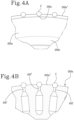
figure 4A shows a front view of a portion of the drum, which is the object of the present invention; -
figure 4B shows a sectional view infigure 4A ; -
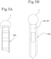
figure 5A shows a side view of a portion of the drum, which is the object of the present invention; -
figure 5B shows a sectional view infigure 5A ; -
figure 6 shows an exploded view of the drum, which is the object of the present invention; -
figure 7A shows a further view of the unit infigure 2 ; -
figure 7B shows an enlargement of a detail infigure 7A : -
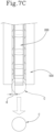
figure 7C shows a different view of the detail infigure 7B in an operating state of the unit. - With reference to the accompanying figures, a drum for inserting discrete components "C" into a continuous strand "B" of the tobacco industry is denoted with 100.
- The term discrete components "C" is understood to mean capsules and, more precisely, capsules having a substantially spherical shape.
- The
drum 100 comprises anouter mantle 200 rotating around an axis of rotation "X". - More specifically, the
drum 100 comprises a stationarycentral hub 600 on which theouter mantle 200 is rotationally mounted. - The
outer mantle 200 preferably comprises, as shown, for example, infigure 2 and infigure 6 , abase portion 200b and aperipheral portion 200a. Thebase portion 200b is radially internal with respect to theperipheral portion 200a and has a width, measured parallel to the axis of rotation "X", which is greater than theperipheral portion 200a. - As shown in the embodiment illustrated in the accompanying figures, the
peripheral portion 200a extends from thebase portion 200b and has a raised shape or radial ribbing. - More specifically, the
peripheral portion 200a has planarparallel side walls 200a', oriented perpendicularly to the axis of rotation "X". In such situation, theperipheral portion 200a is a kind of radial protrusion having a width, measured parallel to the axis of rotation "X", which is less than the width of thebase portion 200b and extending along the whole circumferential extension of thebase portion 200b. - According to embodiments, not shown, the whole
outer mantle 200 has a substantially uniform width in the radial direction, equal to the width of theperipheral portion 200a. - Preferably, the width of the
peripheral portion 200a of theouter mantle 200, measured parallel to the axis of rotation "X", is between 1.5 mm and 3.5 mm. - More preferably, the width of the
peripheral portion 200a of theouter mantle 200, measured parallel to the axis of rotation "X", is approximately equal to two thirds of the diameter of the discrete component "C". - The
drum 100 is provided, on theperipheral portion 200a, with a succession of receivingseats 300, which are angularly distributed around the axis of rotation "X" and in particular, equally spaced apart from one another. - Each receiving
seat 300 is configured to receive a respective discrete component "C". - Each receiving
seat 300 extends along a portion of spherical surface 300'. In fact, as shown infigure 3 , each receivingseat 300 is obtained from theperipheral portion 200a by virtually "digging" the latter, to form a sort of annular-shaped hollow or cup, as will be described in detail hereinafter. - According to an aspect of the present invention, each receiving
seat 300 has a diameter that is greater than the width, measured parallel to the axis of rotation "X", of theperipheral portion 200a of theouter mantle 200 so that a discrete component "C", which is spherical in shape, housed in one of the receivingseats 300 and having a diameter that is greater than the width of theperipheral portion 200a and, at most, equal to the diameter of the receivingseat 300, protrudes axially from theperipheral portion 200a. - In such situation, as shown in
figure 3 and infigure 5A , the discrete component "C", which is housed in the receivingseat 300 so as to be resting on the portion of spherical surface 300' of the receivingseat 300, protrudes, in the axial direction, from theperipheral portion 200a. - In other words, unlike the receiving seats of the drums of the known art (
figure 1 ) in which the diameter of the seat was smaller than the width, measured parallel to the axis of rotation of the drum , of the peripheral portion, the receivingseats 300 of thedrum 100 of the present invention are obtained so as to have a diameter (at least virtual) that is greater than the width of theperipheral portion 200a of theouter mantle 200. In such situation, the discrete component "C" is resting on the portion of spherical surface 300' of the receivingseat 300 but protruding from the receivingseat 300 along the axial direction, i.e. along a direction parallel to the axis of rotation "X". - Preferably, the diameter of each receiving
seat 300 is between 2.5 mm and 5mm, more preferably approximately equal to the diameter of the discrete component "C" plus 0.3 mm. - As shown in
figure 3 and infigure 4A , to allow the discrete component "C" to protrude laterally, theperipheral portion 200a has opposinglateral recesses 300c in each receivingseat 300. In particular, the lateral recesses 300c extend radially inwards from anouter edge 200a" of theperipheral portion 200a. - In the preferred embodiment, each
lateral recess 300c has an arcuate profile and is preferably obtained from an intersection between a virtual sphere, lying on the receivingseat 300 and having the same diameter as the receiving seat 300 (i.e. a diameter that is greater than the width, measured parallel to the axis of rotation "X", of theperipheral portion 200a), and theopposite side walls 200a' of theperipheral portion 200a. - In such situation, as shown, for example, in
figure 4A , eachside wall 200a' of theperipheral portion 200a has a series oflateral recesses 300a, from theouter edge 200a", in the shape of a semi-circle, leaving the lateral zones free of the discrete component "C", which is housed in the receivingseat 300 so that the discrete component "C" protrudes laterally from the receivingseat 300. - Unlike the receiving seats of the drums of the known art (
figure 1 ) in which the discrete component "C" was laterally "wrapped" by the seat, the receivingseats 300 of thedrum 100 of the present invention allow reducing to a minimum the contact surface between the discrete component "C" and the receivingseat 300 leaving free the lateral zones of the discrete component "C" housed in the receivingseat 300 so that the discrete component "C" axially protrudes from the receiving seat 300 (figure 5A ). - In use, at least one succession of discrete components "C" is fed to the receiving
seats 300 of thedrum 100 in at least one receiving zone "R1", "R2". As shown infigure 2 , by way of example, in such receiving zone "R1 ", "R2", one feed drum "T1 ", "T2" can be placed, configured to feed an ordered succession of discrete components "C" to thedrum 100. In such situation, each discrete component "C" is fed to a respective receivingseat 300 so as to protrude laterally from at least one side of thedrum 100. More precisely, each discrete component "C" protrudes axially from theperipheral portion 200a along a direction parallel to the axis of rotation "X" while it is in contact with the receivingseat 300 along the direction of rotation of thedrum 100. - After depositing the discrete components "C", by rotating the
drum 100, each discrete component "C" is taken to a release zone "S" where the discrete components "C" are gradually released from the receivingseats 300 of thedrum 100 to a continuous strand "B". - To prevent the discrete components "C" from falling from the receiving
seats 300, while moving between the at least one receiving zone "R1", "R2" and the release zone "S", they are subjected to an action of pneumatic suction. - To actuate the aforesaid pneumatic suction, as shown in
figure 3 and infigure 4B , each receivingseat 300 is provided with at least onehole 300a in communication with asuction duct 400', 400" connected or connectable to a source of pneumatic suction. - Preferably, the
holes 300a of the receivingseats 300 are aligned along a same circumferential direction. - As shown in detail in
figure 3 , eachhole 300a is made on the bottom of the receivingseat 300 so that therespective suction duct 400', 400" can transmit a retaining action by suction to the discrete component "C". - In further detail, each
suction duct 400', 400" extends, within theperipheral portion 200a, from thehole 300a of the respective receivingseat 300 to anoutlet section 300b', 300b" arranged facing thecentral hub 600. - In such situation, the
central hub 600 is provided with at least one stationary suction chamber suitable for fluid communication with thesuction ducts 400', 400" along an angular stretch around the axis of rotation "X". - Preferably, the angular stretch is the one between the at least one receiving zone "R1 ", "R2" and the release zone "S". In such situation, when the discrete components "C" are gradually fed in the at least one receiving zone "R1", "R2" to the receiving
seats 300, the correspondingsuction ducts 400', 400" are put into fluid communication with the suction chamber, thanks to the rotation of theouter mantle 200, so as to transmit a retaining action to the discrete components "C" until the latter reach the release zone "S". In such situation, the fluid communication between the suction chamber and thesuction ducts 400', 400" associated with the discrete components "C", which have reached the release zone "S" can be interrupted and the discrete components "C" released. - According to a possible embodiment, not shown, the
suction ducts 400', 400" extend radially with respect to the axis of rotation "X" within theperipheral portion 200a and haverespective outlet sections 300b', 300b" arranged facing thecentral hub 600, aligned along one same circumferential direction. In such situation, thecentral hub 600 is provided with only one stationary suction chamber suitable for fluid communication with all thesuction ducts 400', 400". Such embodiment is particularly suitable, for example when only one succession of discrete components "C" is fed to thedrum 100, as in the case infigure 1 . - According to a further possible illustrated embodiment, instead, the
suction ducts 400', 400" are divided into a first succession of suction ducts 400' and into a second succession ofsuction ducts 400" alternated with each other in such a way that eachsuction duct 400" of one of the successions is angularly alternated between two suction ducts 400' of the other succession (figure 4B ). - As shown in
figure 6 , theoutlet sections 300b' of the suction ducts of the first succession 400' and theoutlet sections 300b" of the suction ducts of thesecond succession 400" are mutually arranged along circumferential trajectories, axially offset between one another. - As the
holes 300a of the receivingseats 300 are aligned along one same circumferential direction, but theoutlet sections 300b', 300b" of the first and second succession ofsuction ducts 400', 400" are arranged along circumferential trajectories, which are axially offset between one another, the suction ducts of the first andsecond succession 400', 400" are tilted, i.e. angled with respect to thebase portion 200b and with respect to a radial plane, perpendicular to the axis of rotation of the drum. - In such embodiment, the at least one suction chamber is arranged and/or configured to come into fluid communication with the first succession of suction ducts 400' and the second succession of
suction ducts 400" in different angular positions. Such embodiment is particularly suitable when two successions of discrete components "C" are fed to thedrum 100, as shown, for example, infigure 7A . - In such situation, the at least one suction chamber is configured to come into fluid communication with the first succession of suction ducts 400' from a first receiving zone "R1" in which a first feed drum "T1" feeds a first series of discrete components "C", while it is configured to come into fluid communication with the second succession of
suction ducts 400" only from a second receiving zone "R2" having an angularly offset position with respect to the first receiving zone "R1" and in which a second feed drum "T2" feeds a second series of discrete components "C". - So that the first and second succession of
suction ducts 400', 400" alternately come into fluid communication with the suction chamber, thehub 600 can comprise a single suction chamber having twoadjacent zones figure 7A ) with different angular extensions around the axis of rotation "X". In such situation, a first of thezones 700' is aligned with the circumferential trajectory of the suction ducts of the first succession 400' while the second of thezones 700" is aligned with the circumferential trajectory of the suction ducts of thesecond succession 400". - With reference to the accompanying figures, the
first zone 700' has, around the axis of rotation "X", an angular extension at least equal to the angular distance between the first receiving zone "R1" and the release zone "S" while thesecond zone 700" has, around the axis of rotation "X", an angular extension at least equal to the angular distance between the second receiving zone "R2" and the release zone "S". In such situation, the first and thesecond zone suction ducts 400" of the second series are also in fluid communication with the suction chamber so as to hold the discrete components "C" fed from the second feed drum "T2". - Advantageously, the option of connecting the first and the second series of
suction ducts 400', 400" from a predetermined angular position of thedrum 100 allows reducing losses in pressure and thus reducing the power required by the suction action. - As an alternative to the embodiment in
figure 7A , thehub 600 can have two different suction chambers, which are axially juxtaposed along the axis of rotation "X" and having different angular extensions around the axis of rotation "X". In this case, the first suction chamber is aligned with the circumferential trajectory of the suction ducts of the first succession 400' while the second suction chamber is aligned with the circumferential trajectory of the suction ducts of thesecond succession 400". In this way, along the angular trajectory, around the axis of rotation "X", between the first and the second receiving zone "R1", "R2" the suction ducts 400' of the first series are in fluid communication with the first suction chamber, while the second series ofsuction ducts 400" is not in fluid communication with the second suction chamber. Whereas, starting from the second receiving zone "R2", thesuction ducts 400" of the second series come into fluid communication with the second suction chamber so as to hold the discrete components "C" fed from the second feed drum "T2". - Once the discrete components "C" have been taken to the release zone "S", the latter are released into the underlying continuous strand "B".
- According to an aspect of the present invention, to facilitate the operation of detachment between the discrete components "C" and the respective receiving
seats 300, thedrum 100 comprises at least one detachingelement 500 associated with theperipheral portion 200a. - Preferably, the detaching
element 500 is associated with theperipheral portion 200a of theouter mantle 200 close to the release zone "S" and is stationary in such position. - As shown, for example, in
figure 7A , the detachingelement 500 comprises a fixingend 500b for cantilevering to a stationary structure. - The detaching
element 500 further comprises at least one workingportion 500a defined by a free end opposite to the fixingend 500b. - The working
portion 500a is configured to mechanically remove the discrete components "C" from the respective receivingseats 300 while thedrum 100 rotates around the axis of rotation "X". - Preferably, the at least one working
portion 500a is spaced at a distance "d" from theperipheral portion 200a, measured along the axis of rotation "X", less than 1 mm and/or less than half the difference between the diameter of the receivingseat 300 and the width of theperipheral portion 200a (figure 7C ). - In such situation, the discrete components "C" gradually come into contact with the working
portion 500a, close to the release zone "S". More specifically, each discrete component "C" abuts against the workingportion 500a by a portion thereof axially protruding from the respective receivingseat 300. In such situation, the workingportion 500a acts as a "guide" or "rail" for the discrete component "C" to be detached. - Preferably, the detaching
element 500 is adjustable in position with respect to theperipheral portion 200a. Such aspect is particularly advantageous, as it allows positioning thedetaching element 500 according to the diameter of the discrete components "C" handled so that it can opportunely act on the portions axially protruding from the respective receiving seats 300. - Preferably, in addition, or as an alternative to the option of adjusting the detaching
element 500, the latter can be movable between a working position, suitable for detaching the discrete components "C" from the receivingseats 300, and a non-operating position away from theperipheral portion 200a. - As shown in
figure 7B , during the rotation of theouter mantle 200, close to the release zone "S", a discrete portion "C" abuts against the workingportion 500a of the detachingelement 500. In particular, the discrete component "C" comes into contact with the detachingelement 500 by means of the portion protruding axially from the receivingseat 300. In such situation, while theouter mantle 200 rotates, the discrete component "C" slightly touches the workingportion 500a and is gradually pushed out of the receivingseat 300. - The action of withdrawal of the discrete component "C" from the receiving
seat 300 ends when the discrete component "C" reaches the end of the workingportion 500a. In such situation, the withdrawal of the discrete component "C" from the receivingseat 300 is completed and the discrete component "C" falls into the underlying continuous strand "B" (figure 7B ), in which a longitudinal groove, for example, has previously been made. - According to a possible embodiment, the detaching
element 500 has two workingportions 500a arranged on opposite sides of theperipheral portion 200° so as to act on opposite sides of each discrete component "C". In such situation, the workingportions 500a have respective fixing ends 500b, which are mutually integral and adjustable independently of one another, so as to preferably occupy symmetrical positions with respect to theperipheral portion 200a, to simultaneously act on opposite sides of each discrete component "C". - More preferably, the detaching
element 500 has a forked shape. In such situation, the detachingelement 500 comprises two workingportions 500a arranged on opposite sides of theperipheral portion 200a and asingle fixing end 500b. - In other words, in the case of the forked shape, the two working
portions 500a of the detachingelement 500 extend parallel to each other from onecommon fixing end 500b. In such situation, the two workingportions 500a delimit therebetween a seat for housing theperipheral portion 200a of theouter mantle 200 so that the detachingelement 500 can be mounted straddling thedrum 100. - The detaching
element 500 can determine the detachment of the discrete components "C" from the respective receivingseats 300 both in an embodiment of thedrum 100 in which the suction action in the release zone "S", by thesuction ducts 400', 400", is introduced, and in an embodiment of thedrum 100 in which the air flow passing through thesuction ducts 400', 400" is inverted, pushing the discrete components "C" out of the respective receiving seats 300. - In both the aforesaid embodiments, the detaching
element 500 acts as a "guide" or "slide" configured to promote the detachment of the discrete component "C" and guide the discrete component "C" during the fall thereof towards the continuous strand "B". - The detaching
element 500 can also determine the detachment of the discrete components "C" from the respective receivingseats 300 also in an embodiment of thedrum 100 in which the suction action in the release zone "S" is not interrupted. Also in this situation, the detachingelement 500 acts as a "guide" or "slide" configured to gradually distance the discrete component "C" from the receivingseat 300, overcoming the pneumatic suction action until the latter is no longer impacted by the suction action. - A unit "U" for inserting discrete components "C", in particular capsules, into a continuous strand "B" of the tobacco industry, is also the object of the present invention.
- As shown by way of example in
figure 7A , the unit "U" comprises adrum 100 according to the above description. - The
drum 100 defines a movement path of the receivingseats 300 around the axis of rotation "X" from at least one receiving zone "R1, R2" of the discrete components "C" to a release zone "S" of the discrete components "C". - The unit "U" comprises at least one feed drum "T1", "T2" arranged in the at least one receiving zone "R1", "R2" and configured to feed an ordered succession of discrete components "C" to the
drum 100. - In the illustrated embodiment, the unit "U" comprises two feed drums "T1", "T2" each arranged in a corresponding receiving zone "R1", "R2" and configured to feed, to the
drum 100, a respective ordered succession of discrete components "C". - In such situation, there are provided two receiving zones "R1", "R2" arranged angularly relative to each other along the movement path of the receiving seats 300.
- In the illustrated embodiment, the feed drums "T1", "T2" are configured so that the discrete components "C", fed to the respective receiving zone "R1", "R2", occupy receiving
seats 300, which are not mutually consecutive. In other words, the discrete components "C" are fed so that between two discrete components "C" fed from one of the two feed drums "T1", "T2" a discrete component "C" is alternated and fed to the other of the two drums "T1", "T2". - As described above, in the case of a double feeding of discrete components "C", in order to hold the discrete components "C" in the receiving
seats 300, the suction ducts 400' 400" of thedrum 100 are preferably divided into a first and second successions ofsuction ducts 400', 400" alternated with each other. - In such situation, the first of the feed drums "T1" is arranged and/or configured to feed a succession of discrete components "C" to the receiving
seats 300 associated with the suction ducts of the first succession 400' while the second of the feed drums "T2" is arranged and/or configured to feed a succession of discrete components "C" to the receivingseats 300 associated with the suction ducts of thesecond succession 400". - The unit "U" further comprises guide means (of the known type) for guiding a continuous strand "B" across the release zone "S".
- Therefore, in use, while the continuous strand "B" is gradually caused to advance into the release zone "S", the first and second feed drums "T1", "T2" deposit respective successions of discrete components "C" in the receiving
seats 300 of thedrum 100. - In the first receiving zone "R1", the first feed drum "T1" deposits the discrete components "C" in receiving
seats 300 associated with the first series of suction ducts 400', i.e. with the suction ducts 400' placed in fluid communication with the at least one suction chamber from the first receiving zone "R1". - In the second receiving zone "R2", the second feed drum "T2" deposits the discrete components "C" in the receiving
seats 300 left empty by the discrete components "C" fed from the first feed drum "T1". Such receivingseats 300 are associated with the second series ofsuction ducts 400", which are placed in fluid communication with the at least one suction chamber starting from the second receiving zone "R2". - Starting from the second receiving zone "R2", both the first and the second successions of
suction ducts 400', 400" are placed in fluid communication with the at least one suction chamber so as to hold the discrete components "C" in the receivingseats 300 until the release zone "S" where they are gradually caused to drop in the continuous strand "B". - A method for inserting discrete components "C", in particular capsules, into a continuous strand "B" of the tobacco industry, is also an object of the present invention.
- Such method can be implemented by a "U"-shaped unit according to the above description.
- The method comprises a step of causing a
drum 100 to rotate around an axis of rotation "X". Thedrum 100 comprises anouter mantle 200 rotating around the axis of rotation "X" and is provided, on aperipheral portion 200a thereof, with a succession of receivingseats 300, which are angularly distributed around the axis of rotation "X". - The receiving
seats 300 are provided with at least onehole 300a in communication with asuction duct 400', 400". - The method further comprises a step of feeding at least one succession of discrete components "C" to the receiving
seats 300 of thedrum 100 in at least one receiving zone "R1", "R2" while thedrum 100 is rotating. - Preferably, the feeding step is carried out by at least one feed drum "T1", "T2", which releases, into each receiving
seat 300, one discrete component "C". - Each discrete component "C" is inserted in the respective receiving
seat 300 in such a way that the discrete component "C" protrudes in the direction from the receivingseat 300, in particular by a distance of between 30% and 70% of the dimension, in the radial direction, of the discrete component "C" (figure 5B ). - The method further comprises a step of holding the discrete components "C" in the receiving
seats 300 by pneumatic suction applied in thesuction ducts 400', 400"at least from the at least one receiving zone up "R1", "R2" to a release zone "S" of the discrete components "C". - In other words, at the time of releasing the discrete components "C" in the receiving
seats 300, a pneumatic suction is activated so as to hold the discrete components "C" by suction in the receiving seats 300. - In such situation, the discrete components "C" thus housed and held, are transferred from the at least one receiving zone "R1", "R2" to the release zone "S". During the transfer, each discrete component "C" protrudes laterally from at least one side of the
drum 100. - Preferably, each discrete component "C" is a capsule, more preferably, a spherical capsule. In such situation, the receiving
seats 300 have a diameter that is greater than the width, measured parallel to the axis of rotation "X", of theperipheral portion 200a so that a discrete component "C", housed in one of the receivingseats 300 and having a diameter that is equal to the diameter of the receivingseat 300, protrudes axially from theperipheral portion 200a. - On reaching the release zone "S", the discrete components "C" are released from the receiving
seats 300 of thedrum 100 to a continuous strand "B". - Preferably, the step of releasing the discrete components "C" is accomplished at least partly by a mechanical action applied on a portion of the discrete components "C" protruding laterally from the
drum 100. - In the preferred embodiment, such step is accomplished by the mechanical action applied by the detaching
element 500 according to the preceding description. - The present invention achieves the intended purposes, overcoming the drawbacks of the prior art.
- In particular, the invention allows the discrete components to be carried on the drum in a configuration so as to be transferable with greater precision and control to the continuous strand.
- In particular, the fact that the discrete components protrude laterally from at least one side of the drum optimizes the holding action by the drum, simultaneously allowing mechanical detachment systems to be used in addition to, or in the absence of the interruption of the pneumatic suction in the release zone.
Claims (22)
- A drum (100) for inserting discrete components (C), in particular capsules, into a continuous strand (B) of the tobacco industry, comprising an outer mantle (200) rotating about an axis of rotation (X) and provided, on a peripheral portion (200a) thereof, with a succession of receiving seats (300) which are angularly distributed around the axis of rotation (X) and which are provided with at least one hole (300a) in communication with a suction duct (400', 400") connected or connectable to a source of pneumatic suction, each receiving seat (300) being configured to accommodate a respective discrete component (C) and extending along a portion of spherical surface (300'), each receiving seat (300) having a diameter that is greater than the width, measured parallel to the axis of rotation (X), of the peripheral portion (200a) of the outer mantle (200) so that a discrete component (C), which is spherical in shape, housed in one of the receiving seats (300) and having a diameter that is greater than the width of the peripheral portion (200a) and at most equal in diameter to the receiving seat (300), protrudes axially from the peripheral portion (200a).
- The drum according to claim 1, wherein, at each receiving seat (300), the peripheral portion (200a) has opposing lateral recesses (300c) to allow the discrete component (C) to protrude laterally, in particular the lateral recesses (300c) extending radially inwards from an outer edge (200a") of the peripheral portion (200a).
- The drum according to claim 2, wherein each lateral recess (300c) has an arcuate profile and is preferably obtained from an intersection between a virtual sphere, lying on the receiving seat (300) and having the same diameter as the receiving seat (300), and opposite side walls (200a') of the peripheral portion (200a).
- The drum according to any one of the preceding claims, wherein the peripheral portion (200a) has planar, parallel side walls (200a') oriented perpendicularly to the axis of rotation (X).
- The drum according to any one of the preceding claims, wherein the diameter of each receiving seat (300) is between 2.5 mm and 5 mm, preferably approximately the same as the diameter of the discrete component (C) plus 0.3 mm, and wherein the width of the peripheral portion (200a) of the outer mantle (200), measured parallel to the axis of rotation (X), is between 1.5 mm and 3.5 mm, preferably approximately equal to two thirds of the diameter of the discrete component (C).
- The drum according to any one of the preceding claims, wherein each receiving seat (300) is annular in shape.
- The drum according to any one of the preceding claims, wherein the outer mantle (200) has a radially internal base portion (200b) whose width, measured parallel to the axis of rotation (X), is greater than the peripheral portion (200a).
- The drum according to any one of the preceding claims, comprising at least one detaching element (500) associated with the peripheral portion (200a) and having at least one working portion (500a) configured to mechanically remove the discrete components (C) from the respective receiving seats (300) while the drum (100) rotates about the axis of rotation (X).
- The drum according to claim 8, wherein the detaching element (500) has a fixing end (500b) for cantilevering to a stationary structure, the at least one working portion (500a) being defined by a free end opposite the fixing end (500b).
- The drum according to claim 8 or 9, wherein the detaching element (500) has two working portions (500a) arranged on opposite sides of the peripheral portion (200a) so as to act on opposite sides of each discrete component (C).
- The drum according to claim 10, wherein the detaching element (500) has a forked shape.
- The drum according to any one of claims 8 to 11, wherein at least one working portion (500a) is spaced from the peripheral portion (200a) by a distance (d), measured along the axis of rotation (X), less than 1 mm and/or less than half the difference between the diameter of the receiving seat (300) and the width of the peripheral portion (200a).
- The drum according to any one of claims 8 to 12, wherein the detaching element (500) is operatively stationary and is preferably adjustable in position relative to the peripheral portion (200a) and/or movable between a working position, suitable for detaching the discrete components (C) from the receiving seats (300), and a non-operating position away from the peripheral portion (200a).
- The drum according to any one of the preceding claims, further comprising a stationary, central hub (600) on which the outer mantle (200) is rotationally mounted, wherein the suction ducts (400', 400") of the receiving seats (300) are divided into a first and a second succession of suction ducts (400', 400") alternated with each other in such a way that each suction duct (400") of one of the successions is angularly alternated between two suction ducts (400') of the other succession, and wherein the hub (600) has at least one stationary suction chamber suitable for fluid communication with the suction ducts (400', 400") along an angular stretch around the axis of rotation (X), the at least one suction chamber being arranged and/or configured to come into fluid communication with the first succession of suction ducts (400') and the second succession of ducts (400") at different angular positions.
- The drum according to claim 14, wherein each suction duct (400', 400") extends from the hole (300a) of the respective receiving seat (300) to an outlet section (300b', 300b") facing the central hub (600), wherein the holes (300a) of the receiving seats (300) are aligned along the same circumferential direction, and wherein the outlet sections (300b') of the suction ducts of the first succession (400') and the outlet sections (300b") of the second succession (400") are arranged along circumferential trajectories which are axially staggered from each other.
- The drum according to claim 15, wherein the hub (600) has a single suction chamber having two adjacent zones (700', 700") with different angular extensions around the axis of rotation (X), a first of the zones (700') being aligned with the circumferential trajectory of the suction ducts of the first succession (400'), and the second of the zones (700") being aligned with the circumferential trajectory of the suction ducts of the second succession (400"), or the hub (600) has two suction chambers which are axially juxtaposed along the axis of rotation (X) and having different angular extensions around the axis of rotation (X), the first suction chamber being aligned with the circumferential trajectory of the suction ducts of the first succession (400'), and the second suction chamber being aligned with the circumferential trajectory of the suction ducts of the second succession (400").
- A unit (U) for inserting discrete components, in particular capsules (C) into a continuous strand (B) of the tobacco industry, comprising:a drum (100) according to one or more of the preceding claims, defining a movement path of the receiving seats (300) around the axis of rotation (X) from at least one receiving zone (R1, R2), where the discrete components (C) are received, to a release zone (S), where the discrete components (C) are released;guide means for guiding a continuous strand across the release zone (S);at least one feed drum (T1, T2) arranged in the at least one receiving zone (R1, R2) and configured to feed an ordered succession of discrete components (C) to the drum (100).
- The unit according to claim 17, when dependent on claim 14, comprising two receiving zones (R1, R2) arranged angularly relative to each other along the movement path of the receiving seats (300), the unit (U) comprising a feed drum (T1, T2) arranged in each of the receiving zones (R1, R2), a first of the feed drums (T1) being arranged and/or configured to feed a succession of discrete components (C) to the receiving seats (300) associated with the suction ducts of the first succession (400'), and the second of the feed drums (T2) being arranged and/or configured to feed a succession of discrete components (C) to the receiving seats associated with the suction ducts of the second succession (400").
- A method for inserting discrete components (C), in particular capsules, into a continuous strand (B) of the tobacco industry, in particular implemented by a unit according to claim 17 or 18, comprising the following steps:making a drum (100) rotate about an axis of rotation (X), the drum (100) comprising an outer mantle (200) rotating about the axis of rotation (X) and provided, on a peripheral portion (200a) thereof, with a succession of receiving seats (300) which are angularly distributed around the axis of rotation (X) and which are provided with at least one hole (300a) in communication with a suction duct (400', 400");feeding at least one succession of discrete components (C) to the receiving seats (300) of the drum (100) in at least one receiving zone (R1, R2) while the drum (100) is rotating;holding the discrete components (C) in the receiving seats (300) by pneumatic suction applied in the suction ducts (400', 400") at least from the at least one receiving zone (R1, R2) up to a release zone (S) of the discrete components (C);transferring the discrete components (C), held in the receiving seats (300), from the at least one receiving zone (R1, R2) to the release zone (S);releasing the discrete components (C) from the receiving seats (300) of the drum (100) to a continuous strand (B) in the release zone (S);wherein, during the step of transferring, each discrete component (C) protrudes laterally from at least one side of the drum (100).
- The method according to claim 19, wherein each discrete component (C) is inserted in the respective receiving seat (300) in such a way that the discrete component (C) protrudes radially from the receiving seat (300), in particular by a distance of between 30% and 70% of the radial dimension of the discrete component (C).
- The method according to claim 19 or 20, wherein the step of releasing the discrete components (C) from the receiving seats (300) of the drum (100) to a continuous strand (B) is accomplished at least partly by a mechanical action applied on a portion of the discrete components (C) protruding laterally from the drum (100).
- The method according to any one of claims from 19 to 21, wherein the discrete component (C) is a preferably spherical capsule.
Applications Claiming Priority (1)
| Application Number | Priority Date | Filing Date | Title |
|---|---|---|---|
| IT102023000004170A IT202300004170A1 (en) | 2023-03-07 | 2023-03-07 | DRUM AND METHOD FOR INSERTING DISCRETE COMPONENTS INTO A CONTINUOUS BEAD IN THE TOBACCO INDUSTRY. |
Publications (1)
| Publication Number | Publication Date |
|---|---|
| EP4427605A1 true EP4427605A1 (en) | 2024-09-11 |
Family
ID=86469153
Family Applications (1)
| Application Number | Title | Priority Date | Filing Date |
|---|---|---|---|
| EP23219318.5A Pending EP4427605A1 (en) | 2023-03-07 | 2023-12-21 | A drum and method for inserting discrete components into a continuous strand of the tobacco industry |
Country Status (4)
| Country | Link |
|---|---|
| EP (1) | EP4427605A1 (en) |
| JP (1) | JP2024127843A (en) |
| KR (1) | KR20240136855A (en) |
| IT (1) | IT202300004170A1 (en) |
Citations (4)
| Publication number | Priority date | Publication date | Assignee | Title |
|---|---|---|---|---|
| US20090039102A1 (en) * | 2007-08-10 | 2009-02-12 | Philip Morris Usa Inc. | Bead feeder |
| US20120245007A1 (en) * | 2011-03-25 | 2012-09-27 | Shawn Henley | High speed object inserter and related methods |
| US20130102445A1 (en) * | 2011-03-25 | 2013-04-25 | Hauni Maschinenbau Ag | High speed object inserter and related methods |
| US20190307163A1 (en) * | 2018-04-05 | 2019-10-10 | R. J. Reynolds Tobacco Company | Cigarette filter object insertion apparatus and associated method |
-
2023
- 2023-03-07 IT IT102023000004170A patent/IT202300004170A1/en unknown
- 2023-12-21 EP EP23219318.5A patent/EP4427605A1/en active Pending
-
2024
- 2024-03-05 KR KR1020240031210A patent/KR20240136855A/en active Pending
- 2024-03-06 JP JP2024033916A patent/JP2024127843A/en active Pending
Patent Citations (4)
| Publication number | Priority date | Publication date | Assignee | Title |
|---|---|---|---|---|
| US20090039102A1 (en) * | 2007-08-10 | 2009-02-12 | Philip Morris Usa Inc. | Bead feeder |
| US20120245007A1 (en) * | 2011-03-25 | 2012-09-27 | Shawn Henley | High speed object inserter and related methods |
| US20130102445A1 (en) * | 2011-03-25 | 2013-04-25 | Hauni Maschinenbau Ag | High speed object inserter and related methods |
| US20190307163A1 (en) * | 2018-04-05 | 2019-10-10 | R. J. Reynolds Tobacco Company | Cigarette filter object insertion apparatus and associated method |
Also Published As
| Publication number | Publication date |
|---|---|
| JP2024127843A (en) | 2024-09-20 |
| KR20240136855A (en) | 2024-09-19 |
| IT202300004170A1 (en) | 2024-09-07 |
Similar Documents
| Publication | Publication Date | Title |
|---|---|---|
| EP1594781B1 (en) | Star-shaped conveyor for feeding or discharging empty plastics containers or bottles to or from a machine and orienting and aligning machine having said star-shaped conveyor | |
| KR101504386B1 (en) | Method of compiling groups of segments in a process of producing multisegment filters and apparatus for preparing and compiling segments in groups in a process of producing multisegment filters | |
| EP2928628B1 (en) | Transfer starwheel assembly | |
| EP2682010B1 (en) | Method and unit for uneven transferring of beads | |
| CN110228713B (en) | Conveying roller for tobacco processing industry | |
| US20040237972A1 (en) | Device for combining groups of filter segments for producing multi-segment filters of the tobacco industry, and through drum | |
| EP0383970B1 (en) | Apparatus for manufacturing cigarette filters | |
| EP0134588B1 (en) | Cigarette arranging apparatus | |
| US5047607A (en) | Wire-cutting electric discharge machine with wire sectioning device for wire disposal | |
| JP4495164B2 (en) | Centering drum for filter assembly machine | |
| JP4310390B2 (en) | Unit for supplying products to blistering machines | |
| US20130301376A1 (en) | Portioning and kneading drum | |
| JP5535513B2 (en) | Work sorting device | |
| CN120360303A (en) | Suction roll for a lining device of a machine of the tobacco processing industry | |
| US6408557B1 (en) | Apparatus for producing rifling grooves in a weapon barrel | |
| KR20240136855A (en) | Drum and method for inserting discrete components into a continuous strand of the tobacco industry | |
| KR20080026046A (en) | Rolling Mill Product Handling System | |
| EP1478239B1 (en) | Unit and method for reordering confectionery products, such as sweets and similar | |
| JPH0687526A (en) | Transfer device, transfer mechanism and transfer method for material slices | |
| EP3868225B1 (en) | Unit for axial positioning, specifically centring, for machines for making composite filters | |
| GB2132876A (en) | Cigarette reversing apparatus | |
| JP2004224443A (en) | Unit for conveying capsules to capsule filling machine | |
| US3171315A (en) | Pie crust marker | |
| EP3544451B1 (en) | Method and drum for moving rod-shaped articles of the tobacco industry | |
| WO1982003843A1 (en) | Material orientation apparatus and method |
Legal Events
| Date | Code | Title | Description |
|---|---|---|---|
| PUAI | Public reference made under article 153(3) epc to a published international application that has entered the european phase |
Free format text: ORIGINAL CODE: 0009012 |
|
| STAA | Information on the status of an ep patent application or granted ep patent |
Free format text: STATUS: THE APPLICATION HAS BEEN PUBLISHED |
|
| AK | Designated contracting states |
Kind code of ref document: A1 Designated state(s): AL AT BE BG CH CY CZ DE DK EE ES FI FR GB GR HR HU IE IS IT LI LT LU LV MC ME MK MT NL NO PL PT RO RS SE SI SK SM TR |
|
| STAA | Information on the status of an ep patent application or granted ep patent |
Free format text: STATUS: REQUEST FOR EXAMINATION WAS MADE |
|
| 17P | Request for examination filed |
Effective date: 20250306 |