EP4426069A1 - Dimming method with noise control - Google Patents
Dimming method with noise control Download PDFInfo
- Publication number
- EP4426069A1 EP4426069A1 EP23159338.5A EP23159338A EP4426069A1 EP 4426069 A1 EP4426069 A1 EP 4426069A1 EP 23159338 A EP23159338 A EP 23159338A EP 4426069 A1 EP4426069 A1 EP 4426069A1
- Authority
- EP
- European Patent Office
- Prior art keywords
- duty cycle
- period
- dimming
- dimming value
- pwm signal
- Prior art date
- Legal status (The legal status is an assumption and is not a legal conclusion. Google has not performed a legal analysis and makes no representation as to the accuracy of the status listed.)
- Pending
Links
Images


Classifications
-
- H—ELECTRICITY
- H05—ELECTRIC TECHNIQUES NOT OTHERWISE PROVIDED FOR
- H05B—ELECTRIC HEATING; ELECTRIC LIGHT SOURCES NOT OTHERWISE PROVIDED FOR; CIRCUIT ARRANGEMENTS FOR ELECTRIC LIGHT SOURCES, IN GENERAL
- H05B45/00—Circuit arrangements for operating light-emitting diodes [LED]
- H05B45/10—Controlling the intensity of the light
-
- H—ELECTRICITY
- H05—ELECTRIC TECHNIQUES NOT OTHERWISE PROVIDED FOR
- H05B—ELECTRIC HEATING; ELECTRIC LIGHT SOURCES NOT OTHERWISE PROVIDED FOR; CIRCUIT ARRANGEMENTS FOR ELECTRIC LIGHT SOURCES, IN GENERAL
- H05B45/00—Circuit arrangements for operating light-emitting diodes [LED]
- H05B45/30—Driver circuits
- H05B45/32—Pulse-control circuits
- H05B45/325—Pulse-width modulation [PWM]
-
- H—ELECTRICITY
- H05—ELECTRIC TECHNIQUES NOT OTHERWISE PROVIDED FOR
- H05B—ELECTRIC HEATING; ELECTRIC LIGHT SOURCES NOT OTHERWISE PROVIDED FOR; CIRCUIT ARRANGEMENTS FOR ELECTRIC LIGHT SOURCES, IN GENERAL
- H05B45/00—Circuit arrangements for operating light-emitting diodes [LED]
- H05B45/30—Driver circuits
- H05B45/32—Pulse-control circuits
- H05B45/335—Pulse-frequency modulation [PFM]
-
- H—ELECTRICITY
- H05—ELECTRIC TECHNIQUES NOT OTHERWISE PROVIDED FOR
- H05B—ELECTRIC HEATING; ELECTRIC LIGHT SOURCES NOT OTHERWISE PROVIDED FOR; CIRCUIT ARRANGEMENTS FOR ELECTRIC LIGHT SOURCES, IN GENERAL
- H05B45/00—Circuit arrangements for operating light-emitting diodes [LED]
- H05B45/30—Driver circuits
- H05B45/36—Circuits for reducing or suppressing harmonics, ripples or electromagnetic interferences [EMI]
Definitions
- the present invention relates to the field of controlling the brightness of light by changing the voltage/current waveform applied to an electrical illuminant and in particular to an apparatus and method for generating a pulse width modulation signal for controlling the output power of a driver circuit for an illuminant and/or the brightness of light emitted by the illuminant.
- PWM pulse width modulation
- the brightness is controlled or regulated by changing the width/duration of current or voltage pulses, usually of constant amplitude, within a specified period T.
- the power output in one period results from the amplitude and the duty cycle, a temporal ratio of pulse duration and period.
- PWM dimming can cause audible noise (mechanical vibrations) in driver circuits and/or luminaires at certain frequencies, mostly around as between 1 kHz and 4 kHz.
- the cause is usually in the PWM output stage of the driver circuit including capacitors and inductors.
- the exact component or location often cannot be determined and a general increase in frequency may result in higher costs.
- an object of the present invention is to provide an apparatus and a method, which reduce the above problems.
- an object of the present invention is to provide an apparatus and a method that that can prevent noise with low effort and cost.
- the apparatus is configured to generate a PWM signal for controlling output power of at least one illuminant based on a dimming signal and comprise a control circuit configured to assign, to a dimming value indicated by the dimming signal, a duty cycle of the PWM signal and a period of the duty cycle, wherein the period decreases continuously or discontinuously with an increase of the duty cycle.
- a duty cycle is assigned to each possible dimming value of the signal.
- the duty cycle also changes continuously, i.e., the duty cycle increases with each increase in the dimming value.
- the control circuit can be configured to assign the duty cycle, so that the duty cycle of the PWM signal does not change if the dimming value is constant, in particular that no pulse with a different length is inserted in the PWM signal between pulses with the same length (same duty cycle).
- the apparatus can comprise a control switch or a wired or wireless interface configured to receive a signal from the control switch that can be actuated by the user when noise occurs, wherein the control circuit determines and stores, as a (first) threshold, the current dimming value or the duty cycle assigned to the current dimming value when the switch is actuated and reduces the current/pre-set period by a certain amount when the dimming value reaches or exceeds the (first) threshold.
- a plurality of thresholds can be set if further increasing the dimming value leads to recurrence of noise.
- the manufacturer can determine and store the threshold(s) or can determine and store a table or formula that assigns a period to each dimming value or duty cycle.
- the threshold(s) or the table can be (re)set by the user using a mobile configuration device, wherein the apparatus comprises a transmitter to wirelessly connect the mobile configuration device to the apparatus.
- the control circuit can be configured to decrease the period when the dimming value or the duty cycle assigned to the dimming value reaches or exceeds the first threshold or can be configured to determine the period based on the (first) table or the (first) formula that assigns a period to each dimming value or duty cycle.
- control circuit can be configured to decrease a slew rate of the PWM signal when the dimming value or the duty cycle assigned to the dimming value reaches or exceeds a second threshold or can be configured to determine the slew rate based on a second table or a second formula that assigns a slew rate to each dimming value or duty cycle.
- control circuit can be configured to apply jitter to the PWM signal when the dimming value or the duty cycle assigned to the dimming value reaches or exceeds a third threshold.
- the apparatus is configured to generate a PWM signal for controlling output power of at least one illuminant based on a dimming signal and comprise a control circuit configured to assign a duty cycle of the PWM signal to a dimming value indicated by the dimming signal, wherein the control circuit is configured to determine a period of the duty cycle based on a signal indicating an intensity of mechanical vibrations (noise).
- control circuit can be configured to decrease the period when the intensity reaches or exceeds a first threshold or can be configured to determine the period based on a first table or formula that assigns a period to each intensity.
- control circuit can be configured to decrease a slew rate of the PWM signal when the intensity reaches or exceeds a second threshold or can be configured to determine the slew rate based on a second table or formula that assigns a slew rate to each intensity.
- control circuit can be configured to apply jitter to the PWM signal when the intensity reaches or exceeds a third threshold.
- the first, second and/or third threshold can be stored in the apparatus by the manufacturer and/or can be (re)set by the user using the mobile configuration device or the control switch as described above, wherein the control circuit determines and stores, as a (first) threshold, the current intensity when the control switch is actuated.
- the apparatus can comprise a sensor configured to detect the mechanical vibrations to generate the signal or can comprise an interface (connectors) to connect the sensor to the apparatus.
- the PWM signal can be used to turn a power source or a voltage source on and off, when the illuminant is operated on the power/voltage source, or can be output to a LED driver IC.
- the apparatus can comprise a DC-to-DC converter, wherein the DC-to-DC converter comprises at least one switch controlled by the PWM signal or the control circuit is configured to control the DC-to-DC converter to generate and output the PWM signal to the illuminant.
- the method for generating a PWM signal for controlling output power of at least one illuminant based on a dimming signal comprises assigning, to a dimming value indicated by the dimming signal, a duty cycle of the PWM signal and a period of the duty cycle, wherein the period decreases continuously or discontinuously with an increase of the duty cycle.
- the period can be decreased when the dimming value or the duty cycle assigned to the dimming value reaches or exceeds a first threshold or the period can be determined based on a table or formula that assigns a period to each dimming value or duty cycle.
- the method can further comprise decreasing a slew rate of the PWM signal when the dimming value or the duty cycle assigned to the dimming value reaches or exceeds a second threshold, or determining the slew rate based on a second table or formula that assigns a slew rate to each intensity.
- the method for generating a PWM signal for controlling output power of at least one illuminant based on a dimming signal comprises assigning a duty cycle of the PWM signal to a dimming value indicated by the dimming signal, wherein a period of the duty cycle is determined based on a signal indicating an intensity of mechanical vibrations.
- the period can be decreased when the intensity reaches or exceeds a first threshold or the period is determined based on a first table or formula that assigns a period to each intensity.
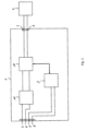
- Fig. 1 shows a LED converter 1 detachably connected to a LED lighting device 2.
- the parts shown in Fig. 1 can be housed in a luminaire.
- the LED converter 1 comprises a light device terminal 3, 4 for connecting the LED lighting device 2 to the LED converter 1, mains terminal 5, 6 (connectors) for connecting the emergency converter 1 to the mains supply, a control terminal 7, 8 for connecting a control line to the LED converter 1, a control circuit 9 connected to the control terminal 7, 8, a power supply unit 10 connected to mains terminal 5, 6 and a LED driver 11 for generating a LED drive current or voltage, which is output via the light device terminal 3, 4 to the LED lighting device 2.
- the LED lighting device 2 fed with the LED light current or voltage emits light from one or more LEDs (not shown).
- the power supply unit 10 fed with the mains supply AC voltage generates a DC voltage for the LED driver 11.
- the control circuit 9 is advantageously a microcontroller circuit or a dedicated application specific integrated circuit (ASIC) and controls the output power of the LED driver 11 based on a dimming signal received via the control terminal 7, 8.
- the dimming signal which can be a DALI-signal, indicates a dimming value of a dimming range from 0.1 % to 100 %.
- the LED driver 11 comprises at least one switch (transistor) controlled by a PWM signal, wherein the control circuit 9 determines the duty cycle of the PWM signal based on the dimming value.
- audible noises occur at certain dimming values, which are reduced by increasing the frequency of the PWM signal several times. More precisely, audible noise occurs at a PWM frequency of 1 kHz from a dimming value of 20%, which can be noticeably reduced by increasing the PWM frequency to 8 kHz. From a dimming value of 50%, audible noise occurs again at the frequency of 8 kHz, which can be reduced by increasing the PWM frequency to 10 kHz.
- the control circuit 9 shown in Fig. 1 determines not only the duty cycle of the PWM signal based on the dimming value but also the frequency of the PWM signal.
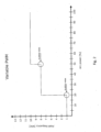
- Fig. 2 shows a diagram with the course of the PWM frequency set by the control circuit 9 as a function of the arc power, which is the relative wattage to the LED lighting device 2 and, in first estimation, the relative luminous flux, and which corresponds to the dimming value.
- PWM frequency of 1 kHz is set in the range from 0.1 % to 20 %
- PWM frequency of 8 kHz is set in the range from 20 % to 50 %
- PWM frequency of 10 kHz is set in the range from 50 % to 100 %.
- the period of the PWM signal decreases discontinuously with an increase of the dimming value, i.e., the duty cycle.
- the ranges and the respective PWM frequency can be stored in a non-volatile memory of the control circuit 9 by the manufacturer or after installation on site.
- Fig. 3 shows a LED converter 1 according to a second embodiment of the present invention, which can detect audible noise (mechanical vibration) and automatically reduce the period of the PWM signal to reduce the noise.
- the LED converter 1 shown in Fig. 3 comprise a sensor configured to detect audible noises (mechanical vibrations) and to output a signal indicating the intensity of the noise (mechanical vibrations) to the control circuit 9, which compares the intensity to a threshold.
- control circuit 9 increases the PWM frequency from 1 kHz to 8 kHz when the intensity reaches or exceeds the threshold, and increases the PWM frequency from 8 kHz to 10 kHz when the intensity again reaches or exceeds the threshold.
- the PWM frequency can be increased stepwise by, for example, 2 kHz until the intensity falls below the threshold.
- Audible noises can be reduced by decreasing the slew rate of the PWM signal and/or applying jitter to the PWM signal.
- Fig. 4 shows a flowchart for a method for determining parameters to reduce audible noises caused by the LED converter 1.
- step S1 the LED converter 1 is turned on and the dimming value is set to 1% in step S2.
- step S3 it is determined whether the intensity reaches or exceeds a threshold. If the intensity does not reach or exceed the threshold, it is determined whether the dimming value is less than or equal to 1% in step S4. If the dimming value is less than or equal to 99%, the dimming value is increased by 1% in step S5 and step S3 is executed again.
- step S3 If the intensity reaches or exceeds the threshold in step S3, jitter is applied to the PWM signal in step S6 and it is determined whether the intensity reaches or exceeds the threshold in step S7. If the intensity does not reach or exceed the threshold, jitter parameter/flag for the current dimming value and PWM frequency is set in a table and step S4 is executed. If the intensity reaches or exceeds the threshold in step S7, the slew rate of the PWM signal is decreased by a certain amount in step S8 and it is determined whether the intensity reaches or exceeds the threshold in step S9. If the intensity does not reach or exceed the threshold, the slew rate for the current dimming value and PWM frequency is set in the table and step S4 is executed.
- the current PWM frequency is increased by a certain amount in step S10 and it is determined whether the intensity reaches or exceeds the threshold in step S3. If the intensity does not reach or exceed the threshold with the increased PWM frequency, the increased PWM frequency is set for the current dimming value in the table and step S4 is executed.
Landscapes
- Physics & Mathematics (AREA)
- Electromagnetism (AREA)
- Circuit Arrangement For Electric Light Sources In General (AREA)
Abstract
Description
- The present invention relates to the field of controlling the brightness of light by changing the voltage/current waveform applied to an electrical illuminant and in particular to an apparatus and method for generating a pulse width modulation signal for controlling the output power of a driver circuit for an illuminant and/or the brightness of light emitted by the illuminant.
- In pulse width modulation (PWM), the brightness is controlled or regulated by changing the width/duration of current or voltage pulses, usually of constant amplitude, within a specified period T. The power output in one period results from the amplitude and the duty cycle, a temporal ratio of pulse duration and period.
- In some cases, PWM dimming can cause audible noise (mechanical vibrations) in driver circuits and/or luminaires at certain frequencies, mostly around as between 1 kHz and 4 kHz. The cause is usually in the PWM output stage of the driver circuit including capacitors and inductors. However, the exact component or location often cannot be determined and a general increase in frequency may result in higher costs.
- It is an object of the present invention to provide an apparatus and a method, which reduce the above problems. In particular, an object of the present invention is to provide an apparatus and a method that that can prevent noise with low effort and cost.
- This object is achieved by the apparatus and the method according to the enclosed independent claims. Advantageous features of the present invention are defined in the corresponding subclaims.
- According to the present invention, the apparatus is configured to generate a PWM signal for controlling output power of at least one illuminant based on a dimming signal and comprise a control circuit configured to assign, to a dimming value indicated by the dimming signal, a duty cycle of the PWM signal and a period of the duty cycle, wherein the period decreases continuously or discontinuously with an increase of the duty cycle.
- Measurements of audible noise confirmed that often a certain noise level is exceeded only at high dimming levels/values. With the present invention, the frequency is raised only at these dimming levels to reduce/prevent the unwanted noise, so that the driver circuit (DC-to-DC converter) can cost-effectively run at low frequency at all other dimming levels.
- A duty cycle is assigned to each possible dimming value of the signal. Preferably, if the dimming value changes continuously, the duty cycle also changes continuously, i.e., the duty cycle increases with each increase in the dimming value. The control circuit can be configured to assign the duty cycle, so that the duty cycle of the PWM signal does not change if the dimming value is constant, in particular that no pulse with a different length is inserted in the PWM signal between pulses with the same length (same duty cycle).
- The manufacturer or user can determine the dimming values at which unwanted noise occurs and at which the frequency should be increased (the period should be decreased). For this, the apparatus can comprise a control switch or a wired or wireless interface configured to receive a signal from the control switch that can be actuated by the user when noise occurs, wherein the control circuit determines and stores, as a (first) threshold, the current dimming value or the duty cycle assigned to the current dimming value when the switch is actuated and reduces the current/pre-set period by a certain amount when the dimming value reaches or exceeds the (first) threshold. In addition, a plurality of thresholds can be set if further increasing the dimming value leads to recurrence of noise. Alternatively, the manufacturer can determine and store the threshold(s) or can determine and store a table or formula that assigns a period to each dimming value or duty cycle. The threshold(s) or the table can be (re)set by the user using a mobile configuration device, wherein the apparatus comprises a transmitter to wirelessly connect the mobile configuration device to the apparatus.
- The control circuit can be configured to decrease the period when the dimming value or the duty cycle assigned to the dimming value reaches or exceeds the first threshold or can be configured to determine the period based on the (first) table or the (first) formula that assigns a period to each dimming value or duty cycle.
- Alternatively or in addition, the control circuit can be configured to decrease a slew rate of the PWM signal when the dimming value or the duty cycle assigned to the dimming value reaches or exceeds a second threshold or can be configured to determine the slew rate based on a second table or a second formula that assigns a slew rate to each dimming value or duty cycle.
- Alternatively or in addition, the control circuit can be configured to apply jitter to the PWM signal when the dimming value or the duty cycle assigned to the dimming value reaches or exceeds a third threshold.
- According to the present invention, the apparatus is configured to generate a PWM signal for controlling output power of at least one illuminant based on a dimming signal and comprise a control circuit configured to assign a duty cycle of the PWM signal to a dimming value indicated by the dimming signal, wherein the control circuit is configured to determine a period of the duty cycle based on a signal indicating an intensity of mechanical vibrations (noise).
- In addition, the control circuit can be configured to decrease the period when the intensity reaches or exceeds a first threshold or can be configured to determine the period based on a first table or formula that assigns a period to each intensity.
- Alternatively or in addition, the control circuit can be configured to decrease a slew rate of the PWM signal when the intensity reaches or exceeds a second threshold or can be configured to determine the slew rate based on a second table or formula that assigns a slew rate to each intensity.
- Alternatively or in addition, the control circuit can be configured to apply jitter to the PWM signal when the intensity reaches or exceeds a third threshold.
- The first, second and/or third threshold can be stored in the apparatus by the manufacturer and/or can be (re)set by the user using the mobile configuration device or the control switch as described above, wherein the control circuit determines and stores, as a (first) threshold, the current intensity when the control switch is actuated.
- The apparatus can comprise a sensor configured to detect the mechanical vibrations to generate the signal or can comprise an interface (connectors) to connect the sensor to the apparatus.
- The PWM signal can be used to turn a power source or a voltage source on and off, when the illuminant is operated on the power/voltage source, or can be output to a LED driver IC. Alternatively, the apparatus can comprise a DC-to-DC converter, wherein the DC-to-DC converter comprises at least one switch controlled by the PWM signal or the control circuit is configured to control the DC-to-DC converter to generate and output the PWM signal to the illuminant.
- According to the present invention, the method for generating a PWM signal for controlling output power of at least one illuminant based on a dimming signal comprises assigning, to a dimming value indicated by the dimming signal, a duty cycle of the PWM signal and a period of the duty cycle, wherein the period decreases continuously or discontinuously with an increase of the duty cycle.
- In addition, the period can be decreased when the dimming value or the duty cycle assigned to the dimming value reaches or exceeds a first threshold or the period can be determined based on a table or formula that assigns a period to each dimming value or duty cycle.
- Alternatively or in addition, the method can further comprise decreasing a slew rate of the PWM signal when the dimming value or the duty cycle assigned to the dimming value reaches or exceeds a second threshold, or determining the slew rate based on a second table or formula that assigns a slew rate to each intensity.
- According to the present invention, the method for generating a PWM signal for controlling output power of at least one illuminant based on a dimming signal comprises assigning a duty cycle of the PWM signal to a dimming value indicated by the dimming signal, wherein a period of the duty cycle is determined based on a signal indicating an intensity of mechanical vibrations.
- The period can be decreased when the intensity reaches or exceeds a first threshold or the period is determined based on a first table or formula that assigns a period to each intensity.
- Embodiments of the invention are discussed in detail with reference to the enclosed figures, in which
-
Fig. 1 shows an apparatus according to a first embodiment of the present invention, -
Fig. 2 shows a diagram with the course of the PWM frequency set by the apparatus shown inFig. 1 as a function of the dimming level, -
Fig. 3 shows an apparatus according to a second embodiment of the present invention, and -
Fig. 4 shows a flowchart for a method for determining parameters to reduce audible noises caused by the apparatus shown inFig. 1 orFig. 3 . - In the figures, same reference numbers denote same or equivalent structures. The explanation of structures with same reference numbers in different figures is avoided where deemed possible for sake of conciseness.
-
Fig. 1 shows aLED converter 1 detachably connected to aLED lighting device 2. The parts shown inFig. 1 can be housed in a luminaire. TheLED converter 1 comprises alight device terminal LED lighting device 2 to theLED converter 1, mains terminal 5, 6 (connectors) for connecting theemergency converter 1 to the mains supply, acontrol terminal LED converter 1, acontrol circuit 9 connected to thecontrol terminal power supply unit 10 connected tomains terminal 5, 6 and aLED driver 11 for generating a LED drive current or voltage, which is output via thelight device terminal LED lighting device 2. TheLED lighting device 2 fed with the LED light current or voltage emits light from one or more LEDs (not shown). Thepower supply unit 10 fed with the mains supply AC voltage generates a DC voltage for theLED driver 11. - The
control circuit 9 is advantageously a microcontroller circuit or a dedicated application specific integrated circuit (ASIC) and controls the output power of theLED driver 11 based on a dimming signal received via thecontrol terminal LED driver 11 comprises at least one switch (transistor) controlled by a PWM signal, wherein thecontrol circuit 9 determines the duty cycle of the PWM signal based on the dimming value. - For the system shown in
Fig. 1 , audible noises (mechanical vibrations) occur at certain dimming values, which are reduced by increasing the frequency of the PWM signal several times. More precisely, audible noise occurs at a PWM frequency of 1 kHz from a dimming value of 20%, which can be noticeably reduced by increasing the PWM frequency to 8 kHz. From a dimming value of 50%, audible noise occurs again at the frequency of 8 kHz, which can be reduced by increasing the PWM frequency to 10 kHz. To reduce audible noises, thecontrol circuit 9 shown inFig. 1 determines not only the duty cycle of the PWM signal based on the dimming value but also the frequency of the PWM signal. -
Fig. 2 shows a diagram with the course of the PWM frequency set by thecontrol circuit 9 as a function of the arc power, which is the relative wattage to theLED lighting device 2 and, in first estimation, the relative luminous flux, and which corresponds to the dimming value. In particular as shown inFig. 2 , PWM frequency of 1 kHz is set in the range from 0.1 % to 20 %, PWM frequency of 8 kHz is set in the range from 20 % to 50 % and PWM frequency of 10 kHz is set in the range from 50 % to 100 %. In this way, the period of the PWM signal decreases discontinuously with an increase of the dimming value, i.e., the duty cycle. The ranges and the respective PWM frequency can be stored in a non-volatile memory of thecontrol circuit 9 by the manufacturer or after installation on site. - The occurrence of noise (mechanical vibrations) may also depend on the type of
LED lighting device 2 or its power.Fig. 3 shows aLED converter 1 according to a second embodiment of the present invention, which can detect audible noise (mechanical vibration) and automatically reduce the period of the PWM signal to reduce the noise. TheLED converter 1 shown inFig. 3 comprise a sensor configured to detect audible noises (mechanical vibrations) and to output a signal indicating the intensity of the noise (mechanical vibrations) to thecontrol circuit 9, which compares the intensity to a threshold. In particular, thecontrol circuit 9 increases the PWM frequency from 1 kHz to 8 kHz when the intensity reaches or exceeds the threshold, and increases the PWM frequency from 8 kHz to 10 kHz when the intensity again reaches or exceeds the threshold. Alternatively, if the intensity reaches or exceeds the threshold, the PWM frequency can be increased stepwise by, for example, 2 kHz until the intensity falls below the threshold. - Audible noises (mechanical vibrations) can be reduced by decreasing the slew rate of the PWM signal and/or applying jitter to the PWM signal.
Fig. 4 shows a flowchart for a method for determining parameters to reduce audible noises caused by theLED converter 1. In step S1, theLED converter 1 is turned on and the dimming value is set to 1% in step S2. In step S3, it is determined whether the intensity reaches or exceeds a threshold. If the intensity does not reach or exceed the threshold, it is determined whether the dimming value is less than or equal to 1% in step S4. If the dimming value is less than or equal to 99%, the dimming value is increased by 1% in step S5 and step S3 is executed again. If the intensity reaches or exceeds the threshold in step S3, jitter is applied to the PWM signal in step S6 and it is determined whether the intensity reaches or exceeds the threshold in step S7. If the intensity does not reach or exceed the threshold, jitter parameter/flag for the current dimming value and PWM frequency is set in a table and step S4 is executed. If the intensity reaches or exceeds the threshold in step S7, the slew rate of the PWM signal is decreased by a certain amount in step S8 and it is determined whether the intensity reaches or exceeds the threshold in step S9. If the intensity does not reach or exceed the threshold, the slew rate for the current dimming value and PWM frequency is set in the table and step S4 is executed. If the intensity reaches or exceeds the threshold, the current PWM frequency is increased by a certain amount in step S10 and it is determined whether the intensity reaches or exceeds the threshold in step S3. If the intensity does not reach or exceed the threshold with the increased PWM frequency, the increased PWM frequency is set for the current dimming value in the table and step S4 is executed.
Claims (15)
- An apparatus for generating a PWM signal for controlling output power of at least one illuminant based on a dimming signal, comprisinga control circuit (9) configured to assign, to a dimming value indicated by the dimming signal, a duty cycle of the PWM signal and a period of the duty cycle, whereinthe period decreases continuously or discontinuously with an increase of the duty cycle.
- The apparatus according to claim 1, wherein
the control circuit (9) is configured to decrease the period when the dimming value or the duty cycle assigned to the dimming value reaches or exceeds a first threshold or is configured to determine the period based on a table or formula that assigns a period to each dimming value or duty cycle. - The apparatus according to claim 1 or 2, wherein
the control circuit (9) is configured to decrease a slew rate of the PWM signal when the dimming value or the duty cycle assigned to the dimming value reaches or exceeds a second threshold or is configured to determine the slew rate based on a second table or formula that assigns a slew rate to each dimming value or duty cycle. - The apparatus according to any one of claims 1 to 3, wherein
the control circuit (9) is configured to apply jitter to the PWM signal when the dimming value or the duty cycle assigned to the dimming value reaches or exceeds a third threshold. - An apparatus for generating a PWM signal for controlling output power of at least one illuminant based on a dimming signal, comprisinga control circuit (9) configured to assign a duty cycle of the PWM signal to a dimming value indicated by the dimming signal, whereinthe control circuit (9) is configured to determine a period of the duty cycle based on a signal indicating an intensity of mechanical vibrations.
- The apparatus according to claim 5, wherein
the control circuit (9) is configured to decrease the period when the intensity reaches or exceeds a first threshold or is configured to determine the period based on a first table or formula that assigns a period to each intensity. - The apparatus according to claim 5 or 6, wherein
the control circuit (9) is configured to decrease a slew rate of the PWM signal when the intensity reaches or exceeds a second threshold or is configured to determine the slew rate based on a second table or formula that assigns a slew rate to each intensity. - The apparatus according to any one of claims 5 to 6, wherein
the control circuit (9) is configured to apply jitter to the PWM signal when the intensity reaches or exceeds a third threshold. - The apparatus according to any one of claims 5 to 8, further comprising
a sensor (12) configured to detect the mechanical vibrations to generate the signal. - The apparatus according to any one of claims 1 to 9, further comprisinga DC-to-DC converter (11), whereinthe DC-to-DC converter (11) comprises at least one switch controlled by the PWM signal or the control circuit (9) is configured to control the DC-to-DC converter (11) to generate and output the PWM signal.
- A method for generating a PWM signal for controlling output power of at least one illuminant based on a dimming signal, comprising the step of:assigning, to a dimming value indicated by the dimming signal, a duty cycle of the PWM signal and a period of the duty cycle, whereinthe period decreases continuously or discontinuously with an increase of the duty cycle.
- The method according to claim 11, wherein
the period is decreased when the dimming value or the duty cycle assigned to the dimming value reaches or exceeds a first threshold or the period is determined based on a table or formula that assigns a period to each dimming value or duty cycle. - The method according to claim 11 or 12, further comprising the step of:decreasing a slew rate of the PWM signal when the dimming value or the duty cycle assigned to the dimming value reaches or exceeds a second threshold, ordetermining the slew rate based on a second table or formula that assigns a slew rate to each intensity.
- A method for generating a PWM signal for controlling output power of at least one illuminant based on a dimming signal, comprising the step of:assigning a duty cycle of the PWM signal to a dimming value indicated by the dimming signal, whereina period of the duty cycle is determined based on a signal indicating an intensity of mechanical vibrations.
- The method according to claim 14, wherein
the period is decreased when the intensity reaches or exceeds a first threshold or the period is determined based on a first table or formula that assigns a period to each intensity.
Priority Applications (1)
| Application Number | Priority Date | Filing Date | Title |
|---|---|---|---|
| EP23159338.5A EP4426069A1 (en) | 2023-03-01 | 2023-03-01 | Dimming method with noise control |
Applications Claiming Priority (1)
| Application Number | Priority Date | Filing Date | Title |
|---|---|---|---|
| EP23159338.5A EP4426069A1 (en) | 2023-03-01 | 2023-03-01 | Dimming method with noise control |
Publications (1)
| Publication Number | Publication Date |
|---|---|
| EP4426069A1 true EP4426069A1 (en) | 2024-09-04 |
Family
ID=85410119
Family Applications (1)
| Application Number | Title | Priority Date | Filing Date |
|---|---|---|---|
| EP23159338.5A Pending EP4426069A1 (en) | 2023-03-01 | 2023-03-01 | Dimming method with noise control |
Country Status (1)
| Country | Link |
|---|---|
| EP (1) | EP4426069A1 (en) |
Citations (4)
| Publication number | Priority date | Publication date | Assignee | Title |
|---|---|---|---|---|
| JP2011242570A (en) * | 2010-05-18 | 2011-12-01 | Mitsubishi Electric Corp | Led video display device |
| US20160212813A1 (en) * | 2014-12-23 | 2016-07-21 | Bridgelux, Inc. | Method on digital deep dimming through combined PWM and PFM |
| US10172197B1 (en) * | 2017-09-22 | 2019-01-01 | Dialog Semiconductor, Inc. | Dimmable single-stage power converter with adaptive switching frequency control |
| US20190230759A1 (en) * | 2018-01-19 | 2019-07-25 | Ledvance Gmbh | PWM Dimming with Reduced Audible Noise |
-
2023
- 2023-03-01 EP EP23159338.5A patent/EP4426069A1/en active Pending
Patent Citations (4)
| Publication number | Priority date | Publication date | Assignee | Title |
|---|---|---|---|---|
| JP2011242570A (en) * | 2010-05-18 | 2011-12-01 | Mitsubishi Electric Corp | Led video display device |
| US20160212813A1 (en) * | 2014-12-23 | 2016-07-21 | Bridgelux, Inc. | Method on digital deep dimming through combined PWM and PFM |
| US10172197B1 (en) * | 2017-09-22 | 2019-01-01 | Dialog Semiconductor, Inc. | Dimmable single-stage power converter with adaptive switching frequency control |
| US20190230759A1 (en) * | 2018-01-19 | 2019-07-25 | Ledvance Gmbh | PWM Dimming with Reduced Audible Noise |
Similar Documents
| Publication | Publication Date | Title |
|---|---|---|
| USRE46715E1 (en) | Forward converter having a primary-side current sense circuit | |
| US8339053B2 (en) | LED dimming apparatus | |
| US9078325B2 (en) | Method and apparatus to control light intensity as voltage fluctuates | |
| US8816598B2 (en) | Circuit and method for driving a luminous means | |
| US8324832B2 (en) | Circuits and methods for controlling power of light sources | |
| JP5047373B2 (en) | LED dimmer | |
| US20130278145A1 (en) | Circuits and methods for driving light sources | |
| US20140184076A1 (en) | Low intensity dimming circuit for an led lamp and method of controlling an led | |
| EP2515611A1 (en) | Lighting device and illumination apparatus | |
| EP3128815B1 (en) | Light-dimming device | |
| EP2458944A1 (en) | Illumination device | |
| RU2718640C2 (en) | Led lighting device | |
| US20130207571A1 (en) | Semiconductor light emitting element drive device and lighting fixture with the same | |
| KR20080011226A (en) | Universal Line Voltage Dimming Method and System | |
| JP2014517466A (en) | LED retrofit drive circuit and method for operating LED retrofit drive circuit | |
| JP5691495B2 (en) | LED driving power supply device and LED lighting device | |
| JP6941807B2 (en) | Lighting device and lighting equipment | |
| RU2595774C2 (en) | Layout for led unit control and operation method thereof | |
| JP6170995B2 (en) | Power supply circuit for lighting equipment | |
| JP5773786B2 (en) | Light source lighting device and lighting fixture | |
| JP5729601B2 (en) | Lighting device | |
| US9497810B1 (en) | Dimmable switching mode LED driving circuit without phase angle measurement | |
| CN114630468B (en) | Biosafety Control of LED Light Sources | |
| US9596729B1 (en) | Dimmable switching mode LED driving circuit without phase angle measurement | |
| JP2017084726A (en) | Lighting device and luminaire |
Legal Events
| Date | Code | Title | Description |
|---|---|---|---|
| PUAI | Public reference made under article 153(3) epc to a published international application that has entered the european phase |
Free format text: ORIGINAL CODE: 0009012 |
|
| STAA | Information on the status of an ep patent application or granted ep patent |
Free format text: STATUS: THE APPLICATION HAS BEEN PUBLISHED |
|
| AK | Designated contracting states |
Kind code of ref document: A1 Designated state(s): AL AT BE BG CH CY CZ DE DK EE ES FI FR GB GR HR HU IE IS IT LI LT LU LV MC ME MK MT NL NO PL PT RO RS SE SI SK SM TR |
|
| STAA | Information on the status of an ep patent application or granted ep patent |
Free format text: STATUS: REQUEST FOR EXAMINATION WAS MADE |
|
| 17P | Request for examination filed |
Effective date: 20241010 |
|
| RBV | Designated contracting states (corrected) |
Designated state(s): AL AT BE BG CH CY CZ DE DK EE ES FI FR GB GR HR HU IE IS IT LI LT LU LV MC ME MK MT NL NO PL PT RO RS SE SI SK SM TR |
|
| GRAP | Despatch of communication of intention to grant a patent |
Free format text: ORIGINAL CODE: EPIDOSNIGR1 |
|
| STAA | Information on the status of an ep patent application or granted ep patent |
Free format text: STATUS: GRANT OF PATENT IS INTENDED |