EP4425945A1 - Visual collection system provided in smart terminal of intelligent logistics vehicle - Google Patents
Visual collection system provided in smart terminal of intelligent logistics vehicle Download PDFInfo
- Publication number
- EP4425945A1 EP4425945A1 EP23802126.5A EP23802126A EP4425945A1 EP 4425945 A1 EP4425945 A1 EP 4425945A1 EP 23802126 A EP23802126 A EP 23802126A EP 4425945 A1 EP4425945 A1 EP 4425945A1
- Authority
- EP
- European Patent Office
- Prior art keywords
- vehicle
- information
- module
- image
- speed
- Prior art date
- Legal status (The legal status is an assumption and is not a legal conclusion. Google has not performed a legal analysis and makes no representation as to the accuracy of the status listed.)
- Pending
Links
Images
Classifications
-
- H—ELECTRICITY
- H04—ELECTRIC COMMUNICATION TECHNIQUE
- H04N—PICTORIAL COMMUNICATION, e.g. TELEVISION
- H04N23/00—Cameras or camera modules comprising electronic image sensors; Control thereof
- H04N23/60—Control of cameras or camera modules
- H04N23/695—Control of camera direction for changing a field of view, e.g. pan, tilt or based on tracking of objects
-
- B—PERFORMING OPERATIONS; TRANSPORTING
- B60—VEHICLES IN GENERAL
- B60W—CONJOINT CONTROL OF VEHICLE SUB-UNITS OF DIFFERENT TYPE OR DIFFERENT FUNCTION; CONTROL SYSTEMS SPECIALLY ADAPTED FOR HYBRID VEHICLES; ROAD VEHICLE DRIVE CONTROL SYSTEMS FOR PURPOSES NOT RELATED TO THE CONTROL OF A PARTICULAR SUB-UNIT
- B60W30/00—Purposes of road vehicle drive control systems not related to the control of a particular sub-unit, e.g. of systems using conjoint control of vehicle sub-units
- B60W30/02—Control of vehicle driving stability
-
- B—PERFORMING OPERATIONS; TRANSPORTING
- B60—VEHICLES IN GENERAL
- B60W—CONJOINT CONTROL OF VEHICLE SUB-UNITS OF DIFFERENT TYPE OR DIFFERENT FUNCTION; CONTROL SYSTEMS SPECIALLY ADAPTED FOR HYBRID VEHICLES; ROAD VEHICLE DRIVE CONTROL SYSTEMS FOR PURPOSES NOT RELATED TO THE CONTROL OF A PARTICULAR SUB-UNIT
- B60W30/00—Purposes of road vehicle drive control systems not related to the control of a particular sub-unit, e.g. of systems using conjoint control of vehicle sub-units
- B60W30/08—Active safety systems predicting or avoiding probable or impending collision or attempting to minimise its consequences
-
- G—PHYSICS
- G05—CONTROLLING; REGULATING
- G05D—SYSTEMS FOR CONTROLLING OR REGULATING NON-ELECTRIC VARIABLES
- G05D1/00—Control of position, course, altitude or attitude of land, water, air or space vehicles, e.g. using automatic pilots
- G05D1/20—Control system inputs
- G05D1/24—Arrangements for determining position or orientation
- G05D1/243—Means capturing signals occurring naturally from the environment, e.g. ambient optical, acoustic, gravitational or magnetic signals
-
- G—PHYSICS
- G05—CONTROLLING; REGULATING
- G05D—SYSTEMS FOR CONTROLLING OR REGULATING NON-ELECTRIC VARIABLES
- G05D1/00—Control of position, course, altitude or attitude of land, water, air or space vehicles, e.g. using automatic pilots
- G05D1/60—Intended control result
- G05D1/617—Safety or protection, e.g. defining protection zones around obstacles or avoiding hazards
- G05D1/622—Obstacle avoidance
-
- G—PHYSICS
- G06—COMPUTING OR CALCULATING; COUNTING
- G06T—IMAGE DATA PROCESSING OR GENERATION, IN GENERAL
- G06T7/00—Image analysis
- G06T7/70—Determining position or orientation of objects or cameras
-
- G—PHYSICS
- G06—COMPUTING OR CALCULATING; COUNTING
- G06T—IMAGE DATA PROCESSING OR GENERATION, IN GENERAL
- G06T7/00—Image analysis
- G06T7/80—Analysis of captured images to determine intrinsic or extrinsic camera parameters, i.e. camera calibration
-
- G—PHYSICS
- G06—COMPUTING OR CALCULATING; COUNTING
- G06V—IMAGE OR VIDEO RECOGNITION OR UNDERSTANDING
- G06V10/00—Arrangements for image or video recognition or understanding
- G06V10/40—Extraction of image or video features
- G06V10/44—Local feature extraction by analysis of parts of the pattern, e.g. by detecting edges, contours, loops, corners, strokes or intersections; Connectivity analysis, e.g. of connected components
-
- G—PHYSICS
- G06—COMPUTING OR CALCULATING; COUNTING
- G06V—IMAGE OR VIDEO RECOGNITION OR UNDERSTANDING
- G06V20/00—Scenes; Scene-specific elements
- G06V20/50—Context or environment of the image
- G06V20/56—Context or environment of the image exterior to a vehicle by using sensors mounted on the vehicle
-
- G—PHYSICS
- G06—COMPUTING OR CALCULATING; COUNTING
- G06V—IMAGE OR VIDEO RECOGNITION OR UNDERSTANDING
- G06V20/00—Scenes; Scene-specific elements
- G06V20/50—Context or environment of the image
- G06V20/56—Context or environment of the image exterior to a vehicle by using sensors mounted on the vehicle
- G06V20/58—Recognition of moving objects or obstacles, e.g. vehicles or pedestrians; Recognition of traffic objects, e.g. traffic signs, traffic lights or roads
-
- G—PHYSICS
- G06—COMPUTING OR CALCULATING; COUNTING
- G06V—IMAGE OR VIDEO RECOGNITION OR UNDERSTANDING
- G06V20/00—Scenes; Scene-specific elements
- G06V20/50—Context or environment of the image
- G06V20/56—Context or environment of the image exterior to a vehicle by using sensors mounted on the vehicle
- G06V20/588—Recognition of the road, e.g. of lane markings; Recognition of the vehicle driving pattern in relation to the road
-
- B—PERFORMING OPERATIONS; TRANSPORTING
- B60—VEHICLES IN GENERAL
- B60W—CONJOINT CONTROL OF VEHICLE SUB-UNITS OF DIFFERENT TYPE OR DIFFERENT FUNCTION; CONTROL SYSTEMS SPECIALLY ADAPTED FOR HYBRID VEHICLES; ROAD VEHICLE DRIVE CONTROL SYSTEMS FOR PURPOSES NOT RELATED TO THE CONTROL OF A PARTICULAR SUB-UNIT
- B60W2420/00—Indexing codes relating to the type of sensors based on the principle of their operation
- B60W2420/40—Photo, light or radio wave sensitive means, e.g. infrared sensors
- B60W2420/403—Image sensing, e.g. optical camera
-
- B—PERFORMING OPERATIONS; TRANSPORTING
- B60—VEHICLES IN GENERAL
- B60W—CONJOINT CONTROL OF VEHICLE SUB-UNITS OF DIFFERENT TYPE OR DIFFERENT FUNCTION; CONTROL SYSTEMS SPECIALLY ADAPTED FOR HYBRID VEHICLES; ROAD VEHICLE DRIVE CONTROL SYSTEMS FOR PURPOSES NOT RELATED TO THE CONTROL OF A PARTICULAR SUB-UNIT
- B60W2520/00—Input parameters relating to overall vehicle dynamics
- B60W2520/10—Longitudinal speed
-
- B—PERFORMING OPERATIONS; TRANSPORTING
- B60—VEHICLES IN GENERAL
- B60W—CONJOINT CONTROL OF VEHICLE SUB-UNITS OF DIFFERENT TYPE OR DIFFERENT FUNCTION; CONTROL SYSTEMS SPECIALLY ADAPTED FOR HYBRID VEHICLES; ROAD VEHICLE DRIVE CONTROL SYSTEMS FOR PURPOSES NOT RELATED TO THE CONTROL OF A PARTICULAR SUB-UNIT
- B60W2552/00—Input parameters relating to infrastructure
- B60W2552/35—Road bumpiness, e.g. potholes
-
- B—PERFORMING OPERATIONS; TRANSPORTING
- B60—VEHICLES IN GENERAL
- B60W—CONJOINT CONTROL OF VEHICLE SUB-UNITS OF DIFFERENT TYPE OR DIFFERENT FUNCTION; CONTROL SYSTEMS SPECIALLY ADAPTED FOR HYBRID VEHICLES; ROAD VEHICLE DRIVE CONTROL SYSTEMS FOR PURPOSES NOT RELATED TO THE CONTROL OF A PARTICULAR SUB-UNIT
- B60W2710/00—Output or target parameters relating to a particular sub-units
- B60W2710/18—Braking system
-
- B—PERFORMING OPERATIONS; TRANSPORTING
- B60—VEHICLES IN GENERAL
- B60W—CONJOINT CONTROL OF VEHICLE SUB-UNITS OF DIFFERENT TYPE OR DIFFERENT FUNCTION; CONTROL SYSTEMS SPECIALLY ADAPTED FOR HYBRID VEHICLES; ROAD VEHICLE DRIVE CONTROL SYSTEMS FOR PURPOSES NOT RELATED TO THE CONTROL OF A PARTICULAR SUB-UNIT
- B60W2720/00—Output or target parameters relating to overall vehicle dynamics
- B60W2720/10—Longitudinal speed
- B60W2720/106—Longitudinal acceleration
-
- B—PERFORMING OPERATIONS; TRANSPORTING
- B60—VEHICLES IN GENERAL
- B60W—CONJOINT CONTROL OF VEHICLE SUB-UNITS OF DIFFERENT TYPE OR DIFFERENT FUNCTION; CONTROL SYSTEMS SPECIALLY ADAPTED FOR HYBRID VEHICLES; ROAD VEHICLE DRIVE CONTROL SYSTEMS FOR PURPOSES NOT RELATED TO THE CONTROL OF A PARTICULAR SUB-UNIT
- B60W30/00—Purposes of road vehicle drive control systems not related to the control of a particular sub-unit, e.g. of systems using conjoint control of vehicle sub-units
- B60W30/08—Active safety systems predicting or avoiding probable or impending collision or attempting to minimise its consequences
- B60W30/095—Predicting travel path or likelihood of collision
- B60W30/0953—Predicting travel path or likelihood of collision the prediction being responsive to vehicle dynamic parameters
-
- B—PERFORMING OPERATIONS; TRANSPORTING
- B60—VEHICLES IN GENERAL
- B60W—CONJOINT CONTROL OF VEHICLE SUB-UNITS OF DIFFERENT TYPE OR DIFFERENT FUNCTION; CONTROL SYSTEMS SPECIALLY ADAPTED FOR HYBRID VEHICLES; ROAD VEHICLE DRIVE CONTROL SYSTEMS FOR PURPOSES NOT RELATED TO THE CONTROL OF A PARTICULAR SUB-UNIT
- B60W40/00—Estimation or calculation of non-directly measurable driving parameters for road vehicle drive control systems not related to the control of a particular sub unit, e.g. by using mathematical models
- B60W40/10—Estimation or calculation of non-directly measurable driving parameters for road vehicle drive control systems not related to the control of a particular sub unit, e.g. by using mathematical models related to vehicle motion
- B60W40/105—Speed
-
- G—PHYSICS
- G05—CONTROLLING; REGULATING
- G05D—SYSTEMS FOR CONTROLLING OR REGULATING NON-ELECTRIC VARIABLES
- G05D2105/00—Specific applications of the controlled vehicles
- G05D2105/20—Specific applications of the controlled vehicles for transportation
- G05D2105/28—Specific applications of the controlled vehicles for transportation of freight
-
- G—PHYSICS
- G05—CONTROLLING; REGULATING
- G05D—SYSTEMS FOR CONTROLLING OR REGULATING NON-ELECTRIC VARIABLES
- G05D2107/00—Specific environments of the controlled vehicles
- G05D2107/70—Industrial sites, e.g. warehouses or factories
-
- G—PHYSICS
- G05—CONTROLLING; REGULATING
- G05D—SYSTEMS FOR CONTROLLING OR REGULATING NON-ELECTRIC VARIABLES
- G05D2109/00—Types of controlled vehicles
- G05D2109/10—Land vehicles
-
- G—PHYSICS
- G05—CONTROLLING; REGULATING
- G05D—SYSTEMS FOR CONTROLLING OR REGULATING NON-ELECTRIC VARIABLES
- G05D2111/00—Details of signals used for control of position, course, altitude or attitude of land, water, air or space vehicles
- G05D2111/10—Optical signals
-
- G—PHYSICS
- G06—COMPUTING OR CALCULATING; COUNTING
- G06T—IMAGE DATA PROCESSING OR GENERATION, IN GENERAL
- G06T2207/00—Indexing scheme for image analysis or image enhancement
- G06T2207/30—Subject of image; Context of image processing
- G06T2207/30248—Vehicle exterior or interior
Definitions
- the present invention belongs to the technical field of an auxiliary control system of vehicles, and particularly relates to a vision acquisition system equipped in an intelligent terminal of a smart logistics vehicle.
- the present application provides a vision acquisition system equipped in an intelligent terminal of a smart logistics vehicle.
- the present invention provides a vision acquisition system equipped in an intelligent terminal of a smart logistics vehicle, which effectively solves the problems in the background.
- a vision acquisition system equipped in an intelligent terminal of a smart logistics vehicle includes an image information acquisition unit, an angle information acquisition unit, a vehicle information acquisition unit, an image information analysis unit and a calculation unit.
- the image information acquisition unit includes a ground image acquisition module and a feature point identification module; the ground image acquisition module acquires a ground image in front of a vehicle through a camera; and the feature point identification module is used for identifying contour information of the image and marking a near point and a far point of the image.
- the angle information acquisition unit includes an angle control module and an angle acquisition module; the angle control module is used for controlling an inclination angle of the camera; and the angle acquisition module is used for acquiring the inclination angle of the camera.
- the vehicle information acquisition unit includes a vehicle speed control module, a vehicle speed acquisition module and a vehicle steering control module; the vehicle speed control module is used for controlling a speed of the vehicle, including braking and acceleration of the vehicle; the vehicle speed acquisition module is used for acquiring a real-time speed of the vehicle; and the vehicle steering control module is used for controlling the steering of the vehicle.
- the image information analysis unit includes an image analysis module and a distance measurement module; the image analysis module is used for analyzing whether there is a pit on the ground image; and the distance measurement module is used for measuring distances from the near point and the far point to a front portion of the vehicle.
- the calculation unit includes a vehicle speed calculation module and a camera inclination angle calculation module; the vehicle speed calculation module is used for calculating a driving speed of the vehicle, so that the vehicle can pass through the pit safely; and the camera inclination angle calculation module is used for calculating the inclination angle of the camera, so that the camera can acquire the satisfactory image.
- the image analysis module of the image acquisition module can also calibrate the pit on the ground, a calibration value is B, and threshold values are set as C1 and C2 according to a width of the pit;
- a friction force provided by the vehicle is F
- the vehicle speed calculation module is internally preset with a following algorithm:
- the camera inclination angle calculation module is preset with the following algorithm,
- the vision acquisition system further includes a storage module; the storage module is used for storing the information of a road surface in front of the vehicle, the information of the road surface includes a width and a depth of the pit and the information of the vehicle passing through the road surface, and the information of the vehicle includes speed information, steering information and weight information of the vehicle; each group of the speed information, the steering information and the weight information of the vehicle form a data set, and is stored in the storage module; the storage module is internally provided with a safety area, a transition area and a dangerous area; and vibration information when the vehicle passes through the road surface safely is calibrated, a calibration value is T0, and threshold values T1 and T2 are set, wherein T1 ⁇ T2.
- the vision acquisition system further includes a comparison module.
- the vehicle weight acquisition module acquires weight information of the vehicle, and marks the weight information as m1.
- the vehicle speed acquisition module acquires the speed information of the vehicle, and marks the speed information as V3.
- the image acquisition module can acquire the distance from the front end of the vehicle to the point A, and marks the distance as H3.
- m1, V3 and H3 are compared with the data set in the storage module so as to output the data set information same as/similar to the data of the vehicle in the safety area, and the vehicle is controlled by the outputted data set information.
- the vision acquisition system further includes a feature selection module; the feature selection module is used for limiting the outputted data set information, including the data set information when the vehicle passes through the pit safely at the maximal speed, or the data set information when the vehicle passes through the pit safely with minimal vehicle vibration, or the data set information when the vehicle passes through the pit safely at a minimal steering angle.
- the feature selection module is used for limiting the outputted data set information, including the data set information when the vehicle passes through the pit safely at the maximal speed, or the data set information when the vehicle passes through the pit safely with minimal vehicle vibration, or the data set information when the vehicle passes through the pit safely at a minimal steering angle.
- the present invention has the following beneficial effects:
- the present invention discloses a vision acquisition system equipped in an intelligent terminal of a smart logistics vehicle, which includes an image information acquisition unit, an angle information acquisition unit, a vehicle information acquisition unit, an image information analysis unit and a calculation unit.
- the image information acquisition unit includes a ground image acquisition module and a feature point identification module; the ground image acquisition module acquires a ground image in front of a vehicle through a camera; and the feature point identification module is used for identifying contour information of the image and marking a near point and a far point of the image.
- a segmentation unit can segment the image, so that the size of the image captured at every time is the same; and moreover, during the segmentation, the image of a point close to the vehicle needs to be reserved.
- the angle information acquisition unit includes an angle control module and an angle acquisition module; the angle control module is used for controlling an inclination angle of a camera; and the angle acquisition module is used for acquiring the inclination angle of the camera.
- the angle of the camera needs to be controlled so as to judge a distance from the vehicle to the uneven position of the road surface, so that a speed of the vehicle is controlled, and the vehicle can pass through the uneven position of the road surface stably at a low speed.
- the vehicle information acquisition unit includes a vehicle speed control module, a vehicle speed acquisition module, a vehicle weight acquisition module, and a vehicle steering control module; the vehicle speed control module is used for controlling the vehicle speed, including braking and acceleration of the vehicle; the speed vehicle acquisition module is used for acquiring a real-time speed of the vehicle; and the vehicle steering control module is used for controlling the steering of the vehicle.
- the vehicle speed control module can control the speed of the vehicle, and the vehicle speed acquisition module can acquire the real-time speed of the vehicle, so that the image acquisition module can acquire the ground image at a suitable position.
- the image information analysis unit includes an image analysis module and a distance measurement module; the image analysis module is used for analyzing whether there is an uneven road section on the ground image, for example, whether there is a pit; the distance measurement module is used for measuring distances from a near point and a far point to a front portion of the vehicle, that is, in an acquired image, the position close to the vehicle is a near point, and the position far from the vehicle is a far point.
- the calculation unit includes a vehicle speed calculation module and a camera inclination angle calculation module; the vehicle speed calculation module is used for calculating a driving speed of the vehicle, so that the vehicle can pass through the pit safely; the camera inclination angle calculation module is used for calculating the inclination angle of the camera, so that the camera can acquire the satisfactory image; and when the vehicle speed increases, the inclination angle of the camera needs to change so as to ensure that the vehicle has a sufficient slow-down buffer distance.
- the image analysis module of the image acquisition module can also calibrate the pit on the ground, a calibration value is B, and threshold values are set as C1 and C2 according to a width of the pit.
- a friction force provided by the vehicle is F, i.e. the friction force that can be provided by a brake disc.
- the friction force is generally a range value.
- the friction force F provided by the vehicle is greater than or equal to F1
- the friction force F provided by the vehicle is greater than or equal to F1
- the vehicle can be decelerated to the preset value in front of the pit of the road surface.
- the camera inclination angle calculation module is also internally preset with the following algorithm,
- the vision acquisition system further includes a storage module; the storage module is used for storing the information of the road surface in front of the vehicle, the information of the road surface includes a width and a depth of the pit, and the information of the vehicle passing through the road surface; the information of the vehicle includes speed information, steering information and weight information of the vehicle; each group of the speed information, the steering information and the weight information of the vehicle form a data set and is stored in the storage module, that is, after the vehicle passes through the pit, the information of the vehicle passing through the pit is recorded; the storage module is internally provided with a safety area, a transition area and a dangerous area; vibration information of the vehicle passing through the road surface safely is calibrated, a calibration value is T0, and threshold values T1 and T2 are set, wherein T1 ⁇ T2; and the information of the vehicle passing through the pit is stored in different areas according to the threshold value.
- the vision acquisition system further includes a comparison module.
- the information of the vehicle is acquired.
- the vehicle weight acquisition module acquires weight information of the vehicle, and marks the weight information as m1.
- the vehicle speed acquisition module acquires speed information of the vehicle, and marks the speed information as V3.
- the image acquisition module can acquire the distance from the front end of the vehicle to the point A, and marks the distance as H3.
- m1, V3 and H3 are compared with the data set in the storage module so as to output the data set information same as/similar to the data of the vehicle in the safety area, and the vehicle is controlled by the outputted data set information.
- the suitable data set information for the vehicle to pass through the front pit is screened out by comparing the information of the with the data set information in the storage module, and the vehicle is controlled by the selected data set information, so that the calculation amount of the calculation module is reduced.
- the vision acquisition system further includes a feature selection module; the feature selection module is used for limiting the outputted data set information, including the data set information when the vehicle passes through the pit safely at a maximal speed, or the data set information when the vehicle passes through the pit safely with minimal vehicle vibration, or the data set information when the vehicle passes through the pit safely at minimal steering.
- relationship terms of first, second and the like herein are just used for differentiating one entity or operation from the other entity or operation, and do not necessarily require or imply any practical relationship or sequence between the entities or operations.
- terms of "comprise”, “include” or any other variant are intended to cover non-exclusive inclusion, so that a process, a method, an article or a device which includes a series of elements not only includes such elements, but also includes other elements not listed clearly or also includes inherent elements in the process, the method, the article or the device.
Landscapes
- Engineering & Computer Science (AREA)
- Physics & Mathematics (AREA)
- General Physics & Mathematics (AREA)
- Theoretical Computer Science (AREA)
- Multimedia (AREA)
- Computer Vision & Pattern Recognition (AREA)
- Automation & Control Theory (AREA)
- Mechanical Engineering (AREA)
- Remote Sensing (AREA)
- Radar, Positioning & Navigation (AREA)
- Aviation & Aerospace Engineering (AREA)
- Transportation (AREA)
- Signal Processing (AREA)
- Traffic Control Systems (AREA)
Abstract
Description
- The present invention belongs to the technical field of an auxiliary control system of vehicles, and particularly relates to a vision acquisition system equipped in an intelligent terminal of a smart logistics vehicle.
- For vehicles, especially unmanned vehicles for carrying goods in factories, in order to reduce the cost, more and more vehicles adopt a driverless technology. The existing unmanned vehicles can make effective judgment if encountering pedestrians or obstacles during driving. However, the existing unmanned technology cannot effectively judge an uneven road surface during the driving. Therefore, the present application provides a vision acquisition system equipped in an intelligent terminal of a smart logistics vehicle.
- In view of the above situation, in order to overcome defects of the prior art, the present invention provides a vision acquisition system equipped in an intelligent terminal of a smart logistics vehicle, which effectively solves the problems in the background.
- In order to achieve the above purpose, the present invention provides the following technical solution: a vision acquisition system equipped in an intelligent terminal of a smart logistics vehicle includes an image information acquisition unit, an angle information acquisition unit, a vehicle information acquisition unit, an image information analysis unit and a calculation unit.
- The image information acquisition unit includes a ground image acquisition module and a feature point identification module; the ground image acquisition module acquires a ground image in front of a vehicle through a camera; and the feature point identification module is used for identifying contour information of the image and marking a near point and a far point of the image.
- The angle information acquisition unit includes an angle control module and an angle acquisition module; the angle control module is used for controlling an inclination angle of the camera; and the angle acquisition module is used for acquiring the inclination angle of the camera.
- The vehicle information acquisition unit includes a vehicle speed control module, a vehicle speed acquisition module and a vehicle steering control module; the vehicle speed control module is used for controlling a speed of the vehicle, including braking and acceleration of the vehicle; the vehicle speed acquisition module is used for acquiring a real-time speed of the vehicle; and the vehicle steering control module is used for controlling the steering of the vehicle.
- The image information analysis unit includes an image analysis module and a distance measurement module; the image analysis module is used for analyzing whether there is a pit on the ground image; and the distance measurement module is used for measuring distances from the near point and the far point to a front portion of the vehicle.
- The calculation unit includes a vehicle speed calculation module and a camera inclination angle calculation module; the vehicle speed calculation module is used for calculating a driving speed of the vehicle, so that the vehicle can pass through the pit safely; and the camera inclination angle calculation module is used for calculating the inclination angle of the camera, so that the camera can acquire the satisfactory image.
- Preferably, the image analysis module of the image acquisition module can also calibrate the pit on the ground, a calibration value is B, and threshold values are set as C1 and C2 according to a width of the pit;
- When B ≤ C1, it means that the vehicle can pass through the pit without slowing down.
- When C1 < B < C2, it means that the vehicle can pass through the pit by slowing down.
- When C2 ≤ B, it means that the vehicle can bypass the pit by steering.
- Preferably, when the vehicle can pass through the pit by slowing down,
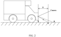
- the near point is marked as a point A, and the far point is marked as a point B;
- the distance from the point A to a front end of the vehicle is marked as H1;
- the driving speed of the vehicle is marked as V1, and the speed of the vehicle safely passing through the pit is marked as V2;
- a braking distance of the vehicle is marked as X;
- so

- A friction force provided by the vehicle is F, and the vehicle speed calculation module is internally preset with a following algorithm:
-

- so that the friction force provided by the vehicle is that F ≥ F1.
- Preferably, the camera inclination angle calculation module is preset with the following algorithm,
-

- the camera inclination angle calculation module is also internally preset with the following algorithm,
-
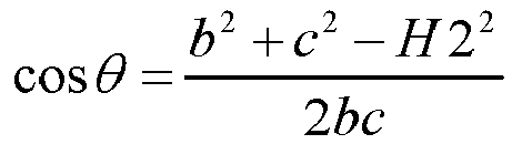
- c is a distance from the camera to the point A;
- θ is an included angle between b and c, i.e., an included angle between the camera and a vertical direction.
- The camera inclination angle calculation module is also internally preset with the following algorithm.

- Preferably, the vision acquisition system further includes a storage module; the storage module is used for storing the information of a road surface in front of the vehicle, the information of the road surface includes a width and a depth of the pit and the information of the vehicle passing through the road surface, and the information of the vehicle includes speed information, steering information and weight information of the vehicle; each group of the speed information, the steering information and the weight information of the vehicle form a data set, and is stored in the storage module; the storage module is internally provided with a safety area, a transition area and a dangerous area; and vibration information when the vehicle passes through the road surface safely is calibrated, a calibration value is T0, and threshold values T1 and T2 are set, wherein T1 < T2.
- When T0 ≤ T1, the information of the vehicle is stored in the safety area of the storage module.
- When T1 < T0 < T2, the information of the vehicle is stored in the transition area of the storage module.
- When T0 ≥ T2, the information of the vehicle is stored in the dangerous area of the storage module.
- Preferably, the vision acquisition system further includes a comparison module.
- The vehicle weight acquisition module acquires weight information of the vehicle, and marks the weight information as m1.
- The vehicle speed acquisition module acquires the speed information of the vehicle, and marks the speed information as V3.
- The image acquisition module can acquire the distance from the front end of the vehicle to the point A, and marks the distance as H3.
- When there is a pit in front of the vehicle, m1, V3 and H3 are compared with the data set in the storage module so as to output the data set information same as/similar to the data of the vehicle in the safety area, and the vehicle is controlled by the outputted data set information.
- Preferably, the vision acquisition system further includes a feature selection module; the feature selection module is used for limiting the outputted data set information, including the data set information when the vehicle passes through the pit safely at the maximal speed, or the data set information when the vehicle passes through the pit safely with minimal vehicle vibration, or the data set information when the vehicle passes through the pit safely at a minimal steering angle.
- Compared with the prior art, the present invention has the following beneficial effects:
- (1) In implementation of the present invention, the road surface in front of the vehicle can be acquired, and when the road surface is uneven and the vehicle needs to slow down, the vehicle can be slowed down in time so as to ensure that the vehicle can cross the uneven road surface stably or can bypass the uneven position, thereby ensuring that the system can help the vehicle to drive more stably in implementation;
- (2) By arranging the camera inclination angle calculation module, the inclination angle of the camera can be controlled, so that when the vehicle speed changes, the image of the road surface in front of the vehicle is acquired, and the vehicle is ensured to have a sufficient buffer distance;
- (3) By acquiring the vehicle data, the suitable data set information for the vehicle to pass through the front pit can be screened out by comparing the information of the vehicle with the data set information stored in the storage module so as to control the vehicle, thereby reducing the calculation amount of the calculation module.
- The drawings are used to provide further understanding for the present invention and constitute part of the description. The drawings are used to explain the present invention together with the embodiments of the present invention, and do not constitute a limitation to the present invention. In the drawings:
-
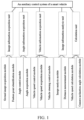
Fig. 1 is a block diagram of a vision acquisition system equipped in an intelligent terminal of a smart logistics vehicle. -
Fig. 2 is a structural schematic diagram of a vision acquisition system equipped in an intelligent terminal of a smart logistics vehicle. - The technical solutions in the embodiments of the present invention will be clearly and fully described below in combination with the drawings in the embodiments of the present invention. Apparently, the described embodiments are merely part of the embodiments of the present invention, not all of the embodiments. Based on the embodiments in the present invention, all other embodiments obtained by those ordinary skilled in the art without contributing creative labor will belong to the protection scope of the present invention.
- As shown in
Fig. 1 to Fig. 2 , the present invention discloses a vision acquisition system equipped in an intelligent terminal of a smart logistics vehicle, which includes an image information acquisition unit, an angle information acquisition unit, a vehicle information acquisition unit, an image information analysis unit and a calculation unit. - The image information acquisition unit includes a ground image acquisition module and a feature point identification module; the ground image acquisition module acquires a ground image in front of a vehicle through a camera; and the feature point identification module is used for identifying contour information of the image and marking a near point and a far point of the image. When the present solution is implemented, in order to accelerate the image processing, after the image is acquired, a segmentation unit can segment the image, so that the size of the image captured at every time is the same; and moreover, during the segmentation, the image of a point close to the vehicle needs to be reserved.
- The angle information acquisition unit includes an angle control module and an angle acquisition module; the angle control module is used for controlling an inclination angle of a camera; and the angle acquisition module is used for acquiring the inclination angle of the camera. During the driving of the vehicle, in order to ensure that the vehicle can stop at an uneven position of a road surface, the angle of the camera needs to be controlled so as to judge a distance from the vehicle to the uneven position of the road surface, so that a speed of the vehicle is controlled, and the vehicle can pass through the uneven position of the road surface stably at a low speed.
- The vehicle information acquisition unit includes a vehicle speed control module, a vehicle speed acquisition module, a vehicle weight acquisition module, and a vehicle steering control module; the vehicle speed control module is used for controlling the vehicle speed, including braking and acceleration of the vehicle; the speed vehicle acquisition module is used for acquiring a real-time speed of the vehicle; and the vehicle steering control module is used for controlling the steering of the vehicle. When the uneven road surface is acquired, the vehicle speed control module can control the speed of the vehicle, and the vehicle speed acquisition module can acquire the real-time speed of the vehicle, so that the image acquisition module can acquire the ground image at a suitable position.
- The image information analysis unit includes an image analysis module and a distance measurement module; the image analysis module is used for analyzing whether there is an uneven road section on the ground image, for example, whether there is a pit; the distance measurement module is used for measuring distances from a near point and a far point to a front portion of the vehicle, that is, in an acquired image, the position close to the vehicle is a near point, and the position far from the vehicle is a far point.
- The calculation unit includes a vehicle speed calculation module and a camera inclination angle calculation module; the vehicle speed calculation module is used for calculating a driving speed of the vehicle, so that the vehicle can pass through the pit safely; the camera inclination angle calculation module is used for calculating the inclination angle of the camera, so that the camera can acquire the satisfactory image; and when the vehicle speed increases, the inclination angle of the camera needs to change so as to ensure that the vehicle has a sufficient slow-down buffer distance.
- The image analysis module of the image acquisition module can also calibrate the pit on the ground, a calibration value is B, and threshold values are set as C1 and C2 according to a width of the pit.
- When B ≤ C1, it means that the vehicle can pass through the pit without slowing down, that is, the width of the pit is small, and when the vehicle passes through the pit, the vehicle may not be affected.
- When C1 < B < C2, it means that the vehicle needs to slow down to pass through the pit, and when the width of the pit is within the range, it means that the vehicle can pass through the pit by slowing down.
- When C2 ≤ B, it means that the vehicle can bypass the pit by steering.
- When the vehicle needs to slow down to pass through the pit,
- the near point is marked as a point A, and the far point is marked as a point B;
- a distance from the point A to the front end of the vehicle is marked as H1;
- a driving speed of the vehicle is marked as V1, and the speed of the vehicle safely passing through the pit is marked as V2;
- a braking distance of the vehicle is marked as X;
- so X ≤ H1.
- That is, it is necessary to ensure that the near point of the image acquired by the camera needs to be greater than the braking distance of the vehicle.
- A friction force provided by the vehicle is F, i.e. the friction force that can be provided by a brake disc. In specific implementation, the friction force is generally a range value. In order to better control the vehicle, an average friction force can be removed, so that the vehicle can be ensured to be decelerated to a preset value normally during the driving; and the vehicle speed calculation module is internally preset with the following algorithm,

- That is, the friction force F provided by the vehicle is greater than or equal to F1, and when the friction force F provided by the vehicle is greater than or equal to F1, the vehicle can be decelerated to the preset value in front of the pit of the road surface.
- Assuming that the vehicle stops moving in front of the pit of the road surface, the camera inclination angle calculation module is preset with the following algorithm,

- The camera inclination angle calculation module is also internally preset with the following algorithm,
-

- c is a distance from the camera to the point A;
- θ is an included angle between b and c, i.e., an included angle between the camera and a vertical direction.
- The camera inclination angle calculation module is also internally preset with the following algorithm,

- In some embodiments, in order to reduce the calculation amount of the calculation module, the following technical solutions are provided:
The vision acquisition system further includes a storage module; the storage module is used for storing the information of the road surface in front of the vehicle, the information of the road surface includes a width and a depth of the pit, and the information of the vehicle passing through the road surface; the information of the vehicle includes speed information, steering information and weight information of the vehicle; each group of the speed information, the steering information and the weight information of the vehicle form a data set and is stored in the storage module, that is, after the vehicle passes through the pit, the information of the vehicle passing through the pit is recorded; the storage module is internally provided with a safety area, a transition area and a dangerous area; vibration information of the vehicle passing through the road surface safely is calibrated, a calibration value is T0, and threshold values T1 and T2 are set, wherein T1 < T2; and the information of the vehicle passing through the pit is stored in different areas according to the threshold value. - When T0 ≤ T1, the information of the vehicle is stored in the safety area of the storage module.
- When T1 < T0 < T2, the information of the vehicle is stored in the transition area of the storage module.
- When T0 ≥ T2, the information of the vehicle is stored in the dangerous area of the storage module.
- The vision acquisition system further includes a comparison module.
- The information of the vehicle is acquired.
- The vehicle weight acquisition module acquires weight information of the vehicle, and marks the weight information as m1.
- The vehicle speed acquisition module acquires speed information of the vehicle, and marks the speed information as V3.
- The image acquisition module can acquire the distance from the front end of the vehicle to the point A, and marks the distance as H3.
- When there is a pit in front of the vehicle, m1, V3 and H3 are compared with the data set in the storage module so as to output the data set information same as/similar to the data of the vehicle in the safety area, and the vehicle is controlled by the outputted data set information.
- By acquiring the vehicle data, the suitable data set information for the vehicle to pass through the front pit is screened out by comparing the information of the with the data set information in the storage module, and the vehicle is controlled by the selected data set information, so that the calculation amount of the calculation module is reduced.
- The vision acquisition system further includes a feature selection module; the feature selection module is used for limiting the outputted data set information, including the data set information when the vehicle passes through the pit safely at a maximal speed, or the data set information when the vehicle passes through the pit safely with minimal vehicle vibration, or the data set information when the vehicle passes through the pit safely at minimal steering.
- It should be noted that relationship terms of first, second and the like herein are just used for differentiating one entity or operation from the other entity or operation, and do not necessarily require or imply any practical relationship or sequence between the entities or operations. Moreover, terms of "comprise", "include" or any other variant are intended to cover non-exclusive inclusion, so that a process, a method, an article or a device which includes a series of elements not only includes such elements, but also includes other elements not listed clearly or also includes inherent elements in the process, the method, the article or the device.
- Although the embodiments of the present invention have been shown and described, it will be appreciated that various variations, amendments, replacements and modifications can be made by those ordinary skilled in the art without departing from the principle and spirit of the present invention, and the scope of the present invention is limited by the appended claims and the equivalents thereof.
Claims (7)
- A vision acquisition system equipped in an intelligent terminal of a smart logistics vehicle, comprising an image information acquisition unit, an angle information acquisition unit, a vehicle information acquisition unit, an image information analysis unit and a calculation unit, whereinthe image information acquisition unit comprises a ground image acquisition module and a feature point identification module; the ground image acquisition module acquires a ground image in front of a vehicle through a camera; and the feature point identification module is used for identifying contour information of the image and marking a near point and a far point of the image;the angle information acquisition unit comprises an angle control module and an angle acquisition module; the angle control module is used for controlling an inclination angle of the camera; and the angle acquisition module is used for acquiring the inclination angle of the camera;the vehicle information acquisition unit comprises a vehicle speed control module, a vehicle speed acquisition module, a vehicle weight acquisition module and a vehicle steering control module; the vehicle speed control module is used for controlling a speed of the vehicle, comprising braking and acceleration of the vehicle; the vehicle speed acquisition module is used for acquiring a real-time speed of the vehicle; and the vehicle steering control module is used for controlling the steering of the vehicle;the image information analysis unit comprises an image analysis module and a distance measurement module; the image analysis module is used for analyzing whether there is a pit on the ground image; and the distance measurement module is used for measuring distances from the near point and the far point to a front portion of the vehicle;the calculation unit comprises a vehicle speed calculation module and a camera inclination angle calculation module; the vehicle speed calculation module is used for calculating a driving speed of the vehicle, so that the vehicle can pass through the pit safely; and the camera inclination angle calculation module is used for calculating the inclination angle of the camera, so that the camera can acquire the satisfactory image.
- The vision acquisition system equipped in the intelligent terminal of the smart logistics vehicle according to claim 1, wherein the image analysis module of the image acquisition module can also calibrate the pit on the ground, a calibration value is B, and threshold values are set as C1 and C2 according to a width of the pit;when B≤C1, it means that the vehicle can pass through the pit without slowing down;when C1 < B< C2, it means that the vehicle can pass through the pit by slowing down;when C2≤B, it means that the vehicle can bypass the pit by steering.
- The vision acquisition system equipped in the intelligent terminal of the smart logistics vehicle according to claim 2, wherein when the vehicle can pass through the pit by slowing down,the near point is marked as a point A, and the far point is marked as a point B;the distance from the point A to a front end of the vehicle is marked as H1;the driving speed of the vehicle is marked as V1, and the speed of the vehicle safely passing through the pit is marked as V2;a braking distance of the vehicle is marked as X,so
 a friction force provided by the vehicle is F, and the vehicle speed calculation module is internally preset with a following algorithm:
 so that the friction force provided by the vehicle is that F ≥ F1.
 - The vision acquisition system equipped in the intelligent terminal of the smart logistics vehicle according to claim 3, wherein the camera inclination angle calculation module is preset with the following algorithm,
 the camera inclination angle calculation module is also internally preset with the following algorithm,
 c is a distance from the camera to the point A;θ is an included angle between b and c, i.e., an included angle between the camera and a vertical direction;the camera inclination angle calculation module is also internally preset with the following algorithm,
- The vision acquisition system equipped in the intelligent terminal of the smart logistics vehicle according to claim 4, further comprising a storage module, wherein the storage module is used for storing the information of a road surface in front of the vehicle, the information of the road surface comprises a width and a depth of the pit and the information of the vehicle passing through the road surface, and the information of the vehicle comprises speed information, steering information and weight information of the vehicle; each group of the speed information, the steering information and the weight information of the vehicle form a data set, and is stored in the storage module; the storage module is internally provided with a safety area, a transition area and a dangerous area; and vibration information when the vehicle passes through the road surface safely is calibrated, a calibration value is T0, and threshold values T1 and T2 are set, wherein T1 < T2;when T0 ≤ T1, the information of the vehicle is stored in the safety area of the storage module;when T1 < T0 < T2, the information of the vehicle is stored in the transition area of the storage module;when T0 ≥ T2, the information of the vehicle is stored in the dangerous area of the storage module.
- The vision acquisition system equipped in the intelligent terminal of the smart logistics vehicle according to claim 5, further comprising a comparison module, whereinthe vehicle weight acquisition module acquires the weight information of the vehicle, and marks the weight information as m1;the vehicle speed acquisition module acquires the speed information of the vehicle, and marks the speed information as V3;the image acquisition module can acquire the distance from the front end of the vehicle to the point A, and marks the distance as H3;when there is a pit in front of the vehicle, m1, V3 and H3 are compared with the data set in the storage module so as to output the data set information same as/similar to the data of the vehicle in the safety area, and the vehicle is controlled by the outputted data set information.
- The vision acquisition system equipped in the intelligent terminal of the smart logistics vehicle according to claim 6, further comprising a feature selection module, wherein the feature selection module is used for limiting the outputted data set information, comprising the data set information when the vehicle passes through the pit safely at the maximal speed, or the data set information when the vehicle passes through the pit safely with minimal vehicle vibration, or the data set information when the vehicle passes through the pit safely at a minimal steering angle.
Applications Claiming Priority (2)
| Application Number | Priority Date | Filing Date | Title |
|---|---|---|---|
| CN202310936575.3A CN116668852B (en) | 2023-07-28 | 2023-07-28 | A visual acquisition system equipped with intelligent terminals for smart logistics vehicles |
| PCT/CN2023/119078 WO2024146166A1 (en) | 2023-07-28 | 2023-09-15 | Visual collection system provided in smart terminal of intelligent logistics vehicle |
Publications (2)
| Publication Number | Publication Date |
|---|---|
| EP4425945A1 true EP4425945A1 (en) | 2024-09-04 |
| EP4425945A4 EP4425945A4 (en) | 2024-11-06 |
Family
ID=91033876
Family Applications (1)
| Application Number | Title | Priority Date | Filing Date |
|---|---|---|---|
| EP23802126.5A Pending EP4425945A4 (en) | 2023-07-28 | 2023-09-15 | Visual collection system provided in smart terminal of intelligent logistics vehicle |
Country Status (2)
| Country | Link |
|---|---|
| US (1) | US11983932B1 (en) |
| EP (1) | EP4425945A4 (en) |
Family Cites Families (17)
| Publication number | Priority date | Publication date | Assignee | Title |
|---|---|---|---|---|
| US5559695A (en) * | 1994-12-27 | 1996-09-24 | Hughes Aircraft Company | Apparatus and method for self-calibrating visual time-to-contact sensor |
| WO2011140993A1 (en) | 2010-05-12 | 2011-11-17 | 北京星河易达科技有限公司 | Intelligent traffic safety system based on comprehensive state detection and decision method thereof |
| US9626763B1 (en) * | 2015-02-25 | 2017-04-18 | Lytx, Inc. | Pothole detection |
| KR102366402B1 (en) * | 2015-05-21 | 2022-02-22 | 엘지전자 주식회사 | Driver assistance apparatus and control method for the same |
| US9535423B1 (en) * | 2016-03-29 | 2017-01-03 | Adasworks Kft. | Autonomous vehicle with improved visual detection ability |
| US20220041184A1 (en) | 2018-10-18 | 2022-02-10 | Caratica Ai Ltd. | Method and system for obstacle detection |
| JP2020147139A (en) * | 2019-03-13 | 2020-09-17 | 本田技研工業株式会社 | Vehicle control devices, vehicle control methods, and programs |
| JP7320074B2 (en) * | 2019-11-28 | 2023-08-02 | 日立Astemo株式会社 | VEHICLE CONTROL DEVICE, VEHICLE CONTROL METHOD, AND VEHICLE CONTROL SYSTEM |
| CN111546891B (en) | 2020-05-27 | 2021-04-13 | 深圳千方智通科技有限公司 | Vehicle safety monitoring management system based on big data |
| JP7427565B2 (en) * | 2020-09-10 | 2024-02-05 | 株式会社東芝 | Information generation device, vehicle control system, information generation method and program |
| US20220281456A1 (en) * | 2020-12-23 | 2022-09-08 | ClearMotion, Inc. | Systems and methods for vehicle control using terrain-based localization |
| CN115331429A (en) | 2021-04-20 | 2022-11-11 | 孙素萍 | Traffic risk perception system based on smart city |
| CN113989775B (en) | 2021-10-28 | 2022-08-05 | 江苏濠汉信息技术有限公司 | Vision-guided auxiliary driving system |
| CN114913449A (en) | 2022-04-14 | 2022-08-16 | 深圳季连科技有限公司 | Road surface camera shooting analysis method for Internet of vehicles |
| CN115273023B (en) | 2022-07-08 | 2026-01-13 | 深蓝汽车科技有限公司 | Vehicle-mounted road pothole identification method, system and automobile |
| CN218782601U (en) | 2022-10-18 | 2023-03-31 | 成争光 | Touch auxiliary driving system |
| CN115892063A (en) | 2022-10-27 | 2023-04-04 | 上海友道智途科技有限公司 | A road condition monitoring and response method for unmanned commercial vehicles |
-
2023
- 2023-09-15 EP EP23802126.5A patent/EP4425945A4/en active Pending
- 2023-10-11 US US18/484,992 patent/US11983932B1/en active Active
Also Published As
| Publication number | Publication date |
|---|---|
| EP4425945A4 (en) | 2024-11-06 |
| US11983932B1 (en) | 2024-05-14 |
Similar Documents
| Publication | Publication Date | Title |
|---|---|---|
| CN113370977B (en) | Intelligent vehicle forward collision early warning method and system based on vision | |
| CN102785661B (en) | Lane departure control system and lane departure control method | |
| CN114559961A (en) | Method and device for avoiding obstacles on road surface of automatic driving vehicle and readable storage medium | |
| CN209946707U (en) | A on-vehicle control system that is used for AGV dolly of warehouse or workshop automatic transportation | |
| EP0448059A2 (en) | Automatic travelling apparatus | |
| CN110738081B (en) | Abnormal road condition detection method and device | |
| CN101131321A (en) | A method and device for real-time measurement of safe vehicle distance for vehicle collision avoidance warning | |
| CN105151043A (en) | Emergency avoidance system and method for unmanned automobile | |
| CN113428180A (en) | Method, system and terminal for controlling single-lane running speed of unmanned vehicle | |
| CN104036279A (en) | Intelligent vehicle running control method and system | |
| CN101135558A (en) | A method and device for vehicle collision avoidance warning based on machine vision | |
| CN104021541A (en) | Vehicle-to-vehicle distance calculation apparatus and method | |
| CN109677402A (en) | The security protection system and method for automatic Pilot tool | |
| US11370429B2 (en) | Distance control for a vehicle with trailer | |
| CN106205148A (en) | A kind of dangerous goods tank car curved road safety speed acquisition methods and hypervelocity caution system | |
| CN116466644B (en) | Vehicle performance supervision system and method based on PLC control | |
| CN114119742B (en) | A method and device for positioning container trucks based on machine vision | |
| CN114942450A (en) | Method for detecting vehicle weighing behavior by laser radar | |
| CN116668852B (en) | A visual acquisition system equipped with intelligent terminals for smart logistics vehicles | |
| EP4425945A1 (en) | Visual collection system provided in smart terminal of intelligent logistics vehicle | |
| CN111724604A (en) | A non-stop speed measurement and weighing system and method for expressway with license plate recognition | |
| CN119527250B (en) | Automobile automatic emergency braking system and control method based on fusion data | |
| CN118046897A (en) | Safe driving control method and system for vehicle | |
| Kalms et al. | Robust lane recognition for autonomous driving | |
| CN115588299B (en) | Unmanned vehicle trajectory control system and method |
Legal Events
| Date | Code | Title | Description |
|---|---|---|---|
| STAA | Information on the status of an ep patent application or granted ep patent |
Free format text: STATUS: UNKNOWN |
|
| STAA | Information on the status of an ep patent application or granted ep patent |
Free format text: STATUS: THE INTERNATIONAL PUBLICATION HAS BEEN MADE |
|
| PUAI | Public reference made under article 153(3) epc to a published international application that has entered the european phase |
Free format text: ORIGINAL CODE: 0009012 |
|
| STAA | Information on the status of an ep patent application or granted ep patent |
Free format text: STATUS: REQUEST FOR EXAMINATION WAS MADE |
|
| 17P | Request for examination filed |
Effective date: 20231124 |
|
| AK | Designated contracting states |
Kind code of ref document: A1 Designated state(s): AL AT BE BG CH CY CZ DE DK EE ES FI FR GB GR HR HU IE IS IT LI LT LU LV MC ME MK MT NL NO PL PT RO RS SE SI SK SM TR |
|
| REG | Reference to a national code |
Ref country code: DE Ref legal event code: R079 Free format text: PREVIOUS MAIN CLASS: H04N0023695000 Ipc: G05D0001243000 |
|
| A4 | Supplementary search report drawn up and despatched |
Effective date: 20241009 |
|
| RIC1 | Information provided on ipc code assigned before grant |
Ipc: H04N 23/695 20230101ALI20241002BHEP Ipc: G05D 1/243 20240101AFI20241002BHEP |
|
| STAA | Information on the status of an ep patent application or granted ep patent |
Free format text: STATUS: EXAMINATION IS IN PROGRESS |
|
| 17Q | First examination report despatched |
Effective date: 20250415 |