EP4425842A1 - Measurement device being activatable via wake-on network capabilities - Google Patents
Measurement device being activatable via wake-on network capabilities Download PDFInfo
- Publication number
- EP4425842A1 EP4425842A1 EP23159808.7A EP23159808A EP4425842A1 EP 4425842 A1 EP4425842 A1 EP 4425842A1 EP 23159808 A EP23159808 A EP 23159808A EP 4425842 A1 EP4425842 A1 EP 4425842A1
- Authority
- EP
- European Patent Office
- Prior art keywords
- measurement device
- wake
- network unit
- network
- measure
- Prior art date
- Legal status (The legal status is an assumption and is not a legal conclusion. Google has not performed a legal analysis and makes no representation as to the accuracy of the status listed.)
- Pending
Links
Images

Classifications
-
- H—ELECTRICITY
- H04—ELECTRIC COMMUNICATION TECHNIQUE
- H04L—TRANSMISSION OF DIGITAL INFORMATION, e.g. TELEGRAPHIC COMMUNICATION
- H04L12/00—Data switching networks
- H04L12/02—Details
- H04L12/12—Arrangements for remote connection or disconnection of substations or of equipment thereof
-
- G—PHYSICS
- G06—COMPUTING OR CALCULATING; COUNTING
- G06F—ELECTRIC DIGITAL DATA PROCESSING
- G06F1/00—Details not covered by groups G06F3/00 - G06F13/00 and G06F21/00
- G06F1/26—Power supply means, e.g. regulation thereof
- G06F1/32—Means for saving power
- G06F1/3203—Power management, i.e. event-based initiation of a power-saving mode
- G06F1/3206—Monitoring of events, devices or parameters that trigger a change in power modality
- G06F1/3209—Monitoring remote activity, e.g. over telephone lines or network connections
-
- H—ELECTRICITY
- H04—ELECTRIC COMMUNICATION TECHNIQUE
- H04W—WIRELESS COMMUNICATION NETWORKS
- H04W24/00—Supervisory, monitoring or testing arrangements
- H04W24/08—Testing, supervising or monitoring using real traffic
-
- H—ELECTRICITY
- H04—ELECTRIC COMMUNICATION TECHNIQUE
- H04B—TRANSMISSION
- H04B17/00—Monitoring; Testing
-
- H—ELECTRICITY
- H04—ELECTRIC COMMUNICATION TECHNIQUE
- H04L—TRANSMISSION OF DIGITAL INFORMATION, e.g. TELEGRAPHIC COMMUNICATION
- H04L12/00—Data switching networks
- H04L12/02—Details
- H04L12/10—Current supply arrangements
-
- H—ELECTRICITY
- H04—ELECTRIC COMMUNICATION TECHNIQUE
- H04L—TRANSMISSION OF DIGITAL INFORMATION, e.g. TELEGRAPHIC COMMUNICATION
- H04L43/00—Arrangements for monitoring or testing data switching networks
- H04L43/50—Testing arrangements
Definitions
- the invention relates to a measurement device being activatable via wake-on network capabilities.
- the invention relates to a measurement device being remotely activatable via wake-on network capabilities, especially wake-on local area network (LAN), and being remotely controllable, a method for remotely operating a measurement device, a computer-readable medium storing computer-executable instructions for performing said method, and a measurement system.
- LAN local area network
- KR 10-1782977 B1 discloses an apparatus for reducing power consumption of a power measurement system by using a measured power value. More specifically, said apparatus comprises a load power measurement system which is installed on a distribution board for supplying power which measures power consumption of a main inlet terminal of the distribution board, and performs a control function corresponding to the measured power consumption; and a plurality of feeder sensors which are connected to the load power measurement system, communicating with the load power measurement system, measuring current consumption of each load terminal, and transmitting the current consumption to the load power measurement system.
- the load power measurement system monitors the power consumption of the main inlet terminal of the distribution board, analyzing the data measured of load power consumption collected by each of the plurality of feeder sensors, and performs a power switching control for reducing power consumption.
- such a configuration does not allow for particularly efficient and energy-saving tests and measurements.
- a measurement device comprises a wake-on network unit for remotely activating the measurement device, and a remote control interface for controlling the functions and/or settings of the measurement device remotely after the measurement device has been activated through the wake-on network unit.
- remote tests and measurements can be performed in a highly efficient and energy-saving manner.
- the measurement device can remotely be powered on when needed and powered off when no more needed, thereby not only saving energy but also prolonging the life of the measurement device.
- the measurement device does not need to provide a standby operating mode because in the sense of the invention, the measurement device is switched off when it is not needed, whereas the wake-on network unit waits at an ultra-low power state for a respective activation message from the corresponding network, especially from the corresponding communication network.
- the wake-on network unit comprises or is a wake-on local area network unit.
- a user datagram protocol packet sent over the corresponding network, especially corresponding communication network can be used for remotely activating the measurement device, thereby increasing efficiency.
- the above-mentioned activation message may comprise or be such a user datagram protocol packet.
- the measurement device and/or the wake-on network unit comprises a remote controllable power socket.
- additional and/or peripheral measurement equipment can be connected to said remote controllable power socket. Accordingly, further advantageously, said additional and/or peripheral measurement equipment can remotely be activated like the measurement device.
- the wake-on network unit is configured to extract energy from the corresponding network, especially from the corresponding communication network, and to supply the measurement device with power on the basis of said energy.
- a mains power line can be omitted.
- the measurement device may comprise an energy storage especially for buffering the extracted energy.
- the wake-on network unit is configured to extract energy from the corresponding network, especially from the corresponding communication network, and to supply the remote controllable power socket with power on the basis of said energy.
- the wake-on network unit comprises a Power over Ethernet port.
- energy can be extracted from the corresponding Ethernet network for supplying the measurement device and/or the remote controllable power socket.
- the measurement device comprises or is a spectrum analyzer especially used to measure the frequency and/or power of signals in wireless communication systems.
- a particularly high flexibility can be ensured, which analogously applies for each of the further preferred implementation forms of the first aspect of the invention as described below.
- the measurement device comprises or is a signal generator especially used to generate test signals for testing and/or calibrating communication systems.
- the measurement device comprises or is a network analyzer especially used to measure the characteristics of communication networks such as frequency response and/or insertion loss.
- the measurement device comprises or is an oscilloscope especially used to measure the voltage and/or time-domain characteristics of electrical signals.
- the measurement device comprises or is a signal analyzer especially used to analyze and/or measure complex signals in wireless communication systems.
- the measurement device comprises or is a power meter and/or a sensor especially used to measure the power of radio frequency and/or microwave signals.
- the measurement device comprises or is a vector network analyzer especially used to measure the scattering parameters of microwave components.
- a method for remotely operating a measurement device comprises the steps of remotely activating the measurement device through a wake-on network unit of the measurement device, and using a remote control interface of the measurement device to remotely control the functions and/or settings of the measurement device after the measurement device has been activated.
- remote tests and measurements can be performed in a highly efficient and energy-saving manner.
- a computer-readable medium stores computer-executable instructions for performing the method according to the second aspect of the invention when executed by a computer.
- remote tests and measurements can be performed in a highly efficient and energy-saving manner.
- a measurement system comprises at least one measurement device according to the first aspect of the invention or any of its preferred implementation forms, respectively, and a remote control device communicating with the Internet and/or at least one of the at least one measurement device.
- a remote control device communicating with the Internet and/or at least one of the at least one measurement device.
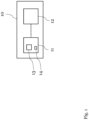
- FIG. 1 a block diagram of an exemplary embodiment of a measurement device 10 is shown.
- Said measurement device 10 comprises a wake-on network unit 11 for remotely activating the measurement device 10, and a remote control interface 12 for controlling the functions and/or settings of the measurement device 10 remotely after the measurement device 10 has been activated through the wake-on network unit 11.
- wake-on network unit 11 may be in connection with the remote control interface 12. Especially in the case that the wake-on network unit 11 is connected to the remote control interface 12, the functions and/or settings of the measurement device 10 may remotely be controlled via the corresponding network, especially via the corresponding communication network, to which the wake-on network unit 11 is connected.
- the functions and/or settings of the measurement device 10 may remotely be controlled in a wireless and/or wired manner especially not via the corresponding network to which the wake-on network unit 11 is connected.
- the wake-on network unit 11 comprises or is a wake-on local area network (LAN) unit.
- LAN local area network
- the wake-on network unit 11 comprises a remote controllable power socket 13.
- additional and/or peripheral measurement equipment can be supplied by said remote controllable power socket 13. Accordingly, power regarding said additional and/or peripheral measurement equipment can by remotely switched on without providing wake-on network capabilities of said additional and/or peripheral measurement equipment by itself.
- the measurement device 10 may comprise a remote controllable power socket such as the above-mentioned remote controllable power socket 13.
- the wake-on network unit 11 exemplarily comprises a Power over Ethernet (PoE) port 14.
- PoE Power over Ethernet
- the wake-on network unit 11 may preferably be configured to extract energy from the corresponding network, especially communication network or Ethernet network, respectively, and to supply the measurement device 10 with power on the basis of said energy.
- the wake-on network unit 11 may preferably be configured to extract energy from the corresponding network, especially communication network or Ethernet network, respectively, and to supply the remote controllable power socket 13 with power on the basis of said energy.
- the measurement device 10 comprises or is a spectrum analyzer especially used to measure the frequency and/or power of signals in wireless communication systems.
- the measurement device 10 may comprise or be a signal generator especially used to generate test signals for testing and/or calibrating communication systems.
- the measurement device 10 may comprise or be a network analyzer especially used to measure the characteristics of communication networks such as frequency response and/or insertion loss.
- the measurement device 10 may comprise or be an oscilloscope especially used to measure the voltage and/or time-domain characteristics of electrical signals.
- the measurement device 10 may comprise or be a signal analyzer especially used to analyze and/or measure complex signals in wireless communication systems.
- the measurement device 10 may comprise or be a power meter and/or a sensor especially used to measure the power of radio frequency and/or microwave signals.
- the measurement device 10 comprises or is a vector network analyzer especially used to measure the scattering parameters of microwave components.
- the measurement device 10 is selected from the group of spectrum analyzers, especially used to measure the frequency and power of signals in wireless communication systems, signal generators, especially used to generate test signals for testing and calibrating communication systems, network analyzers, especially used to measure the characteristics of communication networks, such as frequency response and insertion loss, oscilloscopes, especially used to measure the voltage and time-domain characteristics of electrical signals, signal analyzers, especially used to analyze and measure complex signals in wireless communication systems, power meters and/or sensors, especially used to measure the power of radio frequency and microwave signals, and/or vector network analyzers, especially used to measure the scattering parameters of microwave components.
- spectrum analyzers especially used to measure the frequency and power of signals in wireless communication systems
- signal generators especially used to generate test signals for testing and calibrating communication systems
- network analyzers especially used to measure the characteristics of communication networks, such as frequency response and insertion loss
- oscilloscopes especially used to measure the voltage and time-domain characteristics of electrical signals
- signal analyzers especially used to analyze and measure complex signals in wireless communication systems
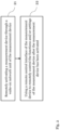
- FIG. 2 a flow chart of an embodiment of the inventive method for remotely operating a measurement device, such as the measurement device 10 according to Fig. 1 , is illustrated.
- a first step 21 of said method comprises remotely activating the measurement device through a wake-on network unit of the measurement device. Additionally, a second step 22 comprises using a remote control interface of the measurement device to remotely control the functions and/or settings of the measurement device after the measurement device has been activated.
- the wake-on network unit comprises or is a wake-on local area network unit.
- the measurement device and/or the wake-on network unit comprises a remote controllable power socket such as the remote controllable power socket 13 of Fig. 1 .
- the method may further comprise the step connecting additional and/or peripheral measurement equipment to the remote controllable power socket. Furthermore, the method may comprise the step of remotely activating the additional and/or peripheral measurement equipment especially with the aid of the measurement device and/or the wake-on network unit.
- the wake-on network unit is configured to extract energy from the corresponding network, especially from the corresponding communication network, and to supply the measurement device with power on the basis of said energy.
- the method may further comprise the step of extracting energy from the corresponding network, especially from the corresponding communication network, with the aid of the wake-on network unit.
- the method may comprise the step of supplying the measurement device and/or the remote controllable power socket with power on the basis of said energy.
- the wake-on network unit comprises a Power over Ethernet port such as the Power over Ethernet port 14 according to Fig. 1 .
- the measurement device comprises or is a spectrum analyzer especially used to measure the frequency and/or power of signals in wireless communication systems.
- the measurement device may comprise or be a signal generator especially used to generate test signals for testing and/or calibrating communication systems.
- the measurement device may comprise or be a network analyzer especially used to measure the characteristics of communication networks such as frequency response and/or insertion loss.
- the measurement device may comprise or be an oscilloscope especially used to measure the voltage and/or time-domain characteristics of electrical signals.
- the measurement device may comprise or be a signal analyzer especially used to analyze and/or measure complex signals in wireless communication systems.
- the measurement device may comprise or be a power meter and/or a sensor especially used to measure the power of radio frequency and/or microwave signals.
- the measurement device comprises or is a vector network analyzer especially used to measure the scattering parameters of microwave components.
- FIG. 3 an exemplary embodiment of an inventive measurement system 30 is depicted.
- said measurement system 30 comprises the measurement device 10 according to Fig. 1 , and a remote control device 31 communicating with the measurement device 10 over the Internet 32.
- the remote control device 31 can directly communicate with the measurement device.
- the remote control device 31 communicates with the Internet 32 and/or the measurement device 10.
- said remote control device 31 may be configured to remotely activate the measurement device 10 especially via the wake-on network unit 11, which is not explicitly shown in Fig. 3 , of the measurement device 10.
- the remote control device 31 may be configured to control the functions and/or settings of the measurement device 10 remotely especially via the remote control interface 12, which is not explicitly shown Fig. 3 , of the measurement device 10 preferably after the measurement device 10 has been activated through the wake-on network unit 11.
- the remote control device 31 comprises or is at least one of a computer, especially a personal computer, a tablet, a smartphone, a measurement device, or any combination thereof.
Landscapes
- Engineering & Computer Science (AREA)
- Computer Networks & Wireless Communication (AREA)
- Signal Processing (AREA)
- Theoretical Computer Science (AREA)
- Physics & Mathematics (AREA)
- General Engineering & Computer Science (AREA)
- General Physics & Mathematics (AREA)
- Electromagnetism (AREA)
- Arrangements For Transmission Of Measured Signals (AREA)
- Mobile Radio Communication Systems (AREA)
Abstract
Description
- The invention relates to a measurement device being activatable via wake-on network capabilities. In particular, the invention relates to a measurement device being remotely activatable via wake-on network capabilities, especially wake-on local area network (LAN), and being remotely controllable, a method for remotely operating a measurement device, a computer-readable medium storing computer-executable instructions for performing said method, and a measurement system.
- Generally, in times of an increasing number of tests and measurements being performed remotely, there is a growing need of a measurement device, a method for remotely operating a measurement device, a computer-readable medium storing computer-executable instructions for performing said method, and a measurement system for performing such remote tests and measurements in a highly efficient and energy-saving manner.
- Document
US 6,477,602 B1 relates to the detection of the presence of a connector in a socket, the connector keeping a pin of the socket to a given level. Said document suggests to take advantage of this for detecting the presence of the connector, by trying to pull the pin to another-level, and determining whether the level on the pin is the given level or the other level. - Furthermore,
KR 10-1782977 B1 - Accordingly, there is the object to provide a measurement device, a method for remotely operating a measurement device, a computer-readable medium storing computer-executable instructions for performing said method, and a measurement system, thereby ensuring a particularly high efficiency and saving of energy.
- This object is solved by the features of the first independent claim for a measurement device, the features of the second independent claim for a method for remotely operating a measurement device, the features of the third independent claim for a computer-readable medium storing computer-executable instructions for performing said method, and the features of the fourth independent claim for a measurement system. The dependent claims contain further developments.
- According to a first aspect of the invention, a measurement device is provided. Said measurement device comprises a wake-on network unit for remotely activating the measurement device, and a remote control interface for controlling the functions and/or settings of the measurement device remotely after the measurement device has been activated through the wake-on network unit. Advantageously, remote tests and measurements can be performed in a highly efficient and energy-saving manner. Further advantageously, the measurement device can remotely be powered on when needed and powered off when no more needed, thereby not only saving energy but also prolonging the life of the measurement device.
- As an additional advantage, it is noted that the measurement device does not need to provide a standby operating mode because in the sense of the invention, the measurement device is switched off when it is not needed, whereas the wake-on network unit waits at an ultra-low power state for a respective activation message from the corresponding network, especially from the corresponding communication network.
- According to a first preferred implementation form of the first aspect of the invention, the wake-on network unit comprises or is a wake-on local area network unit. Advantageously, for instance, a user datagram protocol packet sent over the corresponding network, especially corresponding communication network, can be used for remotely activating the measurement device, thereby increasing efficiency. Accordingly, the above-mentioned activation message may comprise or be such a user datagram protocol packet.
- According to a second preferred implementation form of the first aspect of the invention, the measurement device and/or the wake-on network unit comprises a remote controllable power socket. Advantageously, for example, additional and/or peripheral measurement equipment can be connected to said remote controllable power socket. Accordingly, further advantageously, said additional and/or peripheral measurement equipment can remotely be activated like the measurement device.
- According to a further preferred implementation form of the first aspect of the invention, the wake-on network unit is configured to extract energy from the corresponding network, especially from the corresponding communication network, and to supply the measurement device with power on the basis of said energy. Advantageously, for instance, a mains power line can be omitted. Further advantageously, the measurement device may comprise an energy storage especially for buffering the extracted energy.
- In addition to this or as an alternative, it is noted that it might be particularly advantageous if the wake-on network unit is configured to extract energy from the corresponding network, especially from the corresponding communication network, and to supply the remote controllable power socket with power on the basis of said energy.
- According to a further preferred implementation form of the first aspect of the invention, the wake-on network unit comprises a Power over Ethernet port. Advantageously, for example, energy can be extracted from the corresponding Ethernet network for supplying the measurement device and/or the remote controllable power socket.
- According to a further preferred implementation form of the first aspect of the invention, the measurement device comprises or is a spectrum analyzer especially used to measure the frequency and/or power of signals in wireless communication systems. Advantageously, for instance, a particularly high flexibility can be ensured, which analogously applies for each of the further preferred implementation forms of the first aspect of the invention as described below.
- According to a further preferred implementation form of the first aspect of the invention, the measurement device comprises or is a signal generator especially used to generate test signals for testing and/or calibrating communication systems.
- According to a further preferred implementation form of the first aspect of the invention, the measurement device comprises or is a network analyzer especially used to measure the characteristics of communication networks such as frequency response and/or insertion loss.
- According to a further preferred implementation form of the first aspect of the invention, the measurement device comprises or is an oscilloscope especially used to measure the voltage and/or time-domain characteristics of electrical signals.
- According to a further preferred implementation form of the first aspect of the invention, the measurement device comprises or is a signal analyzer especially used to analyze and/or measure complex signals in wireless communication systems.
- According to a further preferred implementation form of the first aspect of the invention, the measurement device comprises or is a power meter and/or a sensor especially used to measure the power of radio frequency and/or microwave signals.
- According to a further preferred implementation form of the first aspect of the invention, the measurement device comprises or is a vector network analyzer especially used to measure the scattering parameters of microwave components.
- According to a second aspect of the invention, a method for remotely operating a measurement device is provided. Said method comprises the steps of remotely activating the measurement device through a wake-on network unit of the measurement device, and using a remote control interface of the measurement device to remotely control the functions and/or settings of the measurement device after the measurement device has been activated. Advantageously, remote tests and measurements can be performed in a highly efficient and energy-saving manner.
- According to a third aspect of the invention, a computer-readable medium is provided. Said computer-readable medium stores computer-executable instructions for performing the method according to the second aspect of the invention when executed by a computer. Advantageously, remote tests and measurements can be performed in a highly efficient and energy-saving manner.
- According to a fourth aspect of the invention, a measurement system is provided. Said measurement system comprises at least one measurement device according to the first aspect of the invention or any of its preferred implementation forms, respectively, and a remote control device communicating with the Internet and/or at least one of the at least one measurement device. Advantageously, remote tests and measurements can be performed in a highly efficient and energy-saving manner.
- Exemplary embodiments of the invention are now further explained with respect to the drawings by way of example only, and not for limitation. In the drawings:
- Fig. 1
- shows an exemplary embodiment of an inventive measurement device;
- Fig. 2
- shows a flow chart of an embodiment of the second aspect of the invention; and
- Fig. 3
- shows an exemplary embodiment of the inventive measurement system.
- With respect to
Fig. 1 , a block diagram of an exemplary embodiment of ameasurement device 10 is shown. - Said
measurement device 10 comprises a wake-onnetwork unit 11 for remotely activating themeasurement device 10, and aremote control interface 12 for controlling the functions and/or settings of themeasurement device 10 remotely after themeasurement device 10 has been activated through the wake-onnetwork unit 11. - It is noted that wake-on
network unit 11 may be in connection with theremote control interface 12. Especially in the case that the wake-onnetwork unit 11 is connected to theremote control interface 12, the functions and/or settings of themeasurement device 10 may remotely be controlled via the corresponding network, especially via the corresponding communication network, to which the wake-onnetwork unit 11 is connected. - Additionally or alternatively, the functions and/or settings of the
measurement device 10 may remotely be controlled in a wireless and/or wired manner especially not via the corresponding network to which the wake-onnetwork unit 11 is connected. - It is further noted that it might be particularly advantageous if the wake-on
network unit 11 comprises or is a wake-on local area network (LAN) unit. - As it can further be seen from
Fig. 1 , the wake-onnetwork unit 11 comprises a remotecontrollable power socket 13. For instance, additional and/or peripheral measurement equipment can be supplied by said remotecontrollable power socket 13. Accordingly, power regarding said additional and/or peripheral measurement equipment can by remotely switched on without providing wake-on network capabilities of said additional and/or peripheral measurement equipment by itself. - In addition to this or as an alternative, it is noted that the
measurement device 10 may comprise a remote controllable power socket such as the above-mentioned remotecontrollable power socket 13. - Moreover, the wake-on
network unit 11 exemplarily comprises a Power over Ethernet (PoE)port 14. In this context, the wake-onnetwork unit 11 may preferably be configured to extract energy from the corresponding network, especially communication network or Ethernet network, respectively, and to supply themeasurement device 10 with power on the basis of said energy. - Additionally or alternatively, the wake-on
network unit 11 may preferably be configured to extract energy from the corresponding network, especially communication network or Ethernet network, respectively, and to supply the remotecontrollable power socket 13 with power on the basis of said energy. - It is noted that it might be particularly advantageous if the
measurement device 10 comprises or is a spectrum analyzer especially used to measure the frequency and/or power of signals in wireless communication systems. - Furthermore, the
measurement device 10 may comprise or be a signal generator especially used to generate test signals for testing and/or calibrating communication systems. - Moreover, the
measurement device 10 may comprise or be a network analyzer especially used to measure the characteristics of communication networks such as frequency response and/or insertion loss. - Additionally or alternatively, the
measurement device 10 may comprise or be an oscilloscope especially used to measure the voltage and/or time-domain characteristics of electrical signals. - Further additionally or further alternatively, the
measurement device 10 may comprise or be a signal analyzer especially used to analyze and/or measure complex signals in wireless communication systems. - In further addition to this or as a further alternative, the
measurement device 10 may comprise or be a power meter and/or a sensor especially used to measure the power of radio frequency and/or microwave signals. - It is further noted that it might be particularly advantageous if the
measurement device 10 comprises or is a vector network analyzer especially used to measure the scattering parameters of microwave components. - On the basis of the explanations above, it is noted that it might basically be advantageous if the
measurement device 10 is selected from the group of spectrum analyzers, especially used to measure the frequency and power of signals in wireless communication systems, signal generators, especially used to generate test signals for testing and calibrating communication systems, network analyzers, especially used to measure the characteristics of communication networks, such as frequency response and insertion loss, oscilloscopes, especially used to measure the voltage and time-domain characteristics of electrical signals, signal analyzers, especially used to analyze and measure complex signals in wireless communication systems, power meters and/or sensors, especially used to measure the power of radio frequency and microwave signals, and/or vector network analyzers, especially used to measure the scattering parameters of microwave components. - Now, with respect to
Fig. 2 , a flow chart of an embodiment of the inventive method for remotely operating a measurement device, such as themeasurement device 10 according toFig. 1 , is illustrated. - A
first step 21 of said method comprises remotely activating the measurement device through a wake-on network unit of the measurement device. Additionally, asecond step 22 comprises using a remote control interface of the measurement device to remotely control the functions and/or settings of the measurement device after the measurement device has been activated. - With respect to the wake-on network unit, it is noted that it might be particularly advantageous if the wake-on network unit comprises or is a wake-on local area network unit.
- It is further noted that it might be particularly advantageous if the measurement device and/or the wake-on network unit comprises a remote controllable power socket such as the remote
controllable power socket 13 ofFig. 1 . - In this context, the method may further comprise the step connecting additional and/or peripheral measurement equipment to the remote controllable power socket. Furthermore, the method may comprise the step of remotely activating the additional and/or peripheral measurement equipment especially with the aid of the measurement device and/or the wake-on network unit.
- It is noted that it might be particularly advantageous if the wake-on network unit is configured to extract energy from the corresponding network, especially from the corresponding communication network, and to supply the measurement device with power on the basis of said energy.
- In other words, the method may further comprise the step of extracting energy from the corresponding network, especially from the corresponding communication network, with the aid of the wake-on network unit. Moreover, the method may comprise the step of supplying the measurement device and/or the remote controllable power socket with power on the basis of said energy.
- Especially in this context, it is noted that it might be particularly advantageous if the wake-on network unit comprises a Power over Ethernet port such as the Power over
Ethernet port 14 according toFig. 1 . - It is further noted that it might be particularly advantageous if the measurement device comprises or is a spectrum analyzer especially used to measure the frequency and/or power of signals in wireless communication systems.
- Furthermore, the measurement device may comprise or be a signal generator especially used to generate test signals for testing and/or calibrating communication systems.
- Moreover, the measurement device may comprise or be a network analyzer especially used to measure the characteristics of communication networks such as frequency response and/or insertion loss.
- Additionally or alternatively, the measurement device may comprise or be an oscilloscope especially used to measure the voltage and/or time-domain characteristics of electrical signals.
- Further additionally or further alternatively, the measurement device may comprise or be a signal analyzer especially used to analyze and/or measure complex signals in wireless communication systems.
- In further addition to this or as a further alternative, the measurement device may comprise or be a power meter and/or a sensor especially used to measure the power of radio frequency and/or microwave signals.
- It is further noted that it might be particularly advantageous if the measurement device comprises or is a vector network analyzer especially used to measure the scattering parameters of microwave components.
- Finally, with respect to
Fig. 3 , an exemplary embodiment of aninventive measurement system 30 is depicted. - Exemplarily, said
measurement system 30 comprises themeasurement device 10 according toFig. 1 , and aremote control device 31 communicating with themeasurement device 10 over theInternet 32. - In addition to this or as an alternative, it is noted that the
remote control device 31 can directly communicate with the measurement device. - In other words, it might be particularly advantageous if the
remote control device 31 communicates with theInternet 32 and/or themeasurement device 10. - Furthermore, with respect to the
remote control device 31, it is noted that saidremote control device 31 may be configured to remotely activate themeasurement device 10 especially via the wake-onnetwork unit 11, which is not explicitly shown inFig. 3 , of themeasurement device 10. - Additionally or alternatively, the
remote control device 31 may be configured to control the functions and/or settings of themeasurement device 10 remotely especially via theremote control interface 12, which is not explicitly shownFig. 3 , of themeasurement device 10 preferably after themeasurement device 10 has been activated through the wake-onnetwork unit 11. - In further addition to this or as a further alternative, it is noted that it might be particularly advantageous if the
remote control device 31 comprises or is at least one of a computer, especially a personal computer, a tablet, a smartphone, a measurement device, or any combination thereof. - While various embodiments of the present invention have been described above, it should be understood that they have been presented by way of example only, and not limitation. Numerous changes to the disclosed embodiments can be made in accordance with the disclosure herein without departing from the spirit or scope of the invention. Thus, the breadth and scope of the present invention should not be limited by any of the above described embodiments. Rather, the scope of the invention should be defined in accordance with the following claims and their equivalents.
- Although the invention has been illustrated and described with respect to one or more implementations, equivalent alterations and modifications will occur to others skilled in the art upon the reading and understanding of this specification and the annexed drawings. In addition, while a particular feature of the invention may have been disclosed with respect to only one of several implementations, such feature may be combined with one or more other features of the other implementations as may be desired and advantageous for any given or particular application.
Claims (15)
- A measurement device (10) comprising:a wake-on network unit (11) for remotely activating the measurement device (10), anda remote control interface (12) for controlling the functions and/or settings of the measurement device (10) remotely after the measurement device (10) has been activated through the wake-on network unit (11).
- The measurement device (10) according to claim 1, wherein the wake-on network unit (11) comprises or is a wake-on local area network unit.
- The measurement device (10) according to claim 1 or 2, wherein the measurement device (10) and/or the wake-on network unit (11) comprises a remote controllable power socket (13).
- The measurement device (10) according to any of the claims 1 to 3,
wherein the wake-on network unit (11) is configured to extract energy from the corresponding network, especially from the corresponding communication network, and to supply the measurement device (10) with power on the basis of said energy. - The measurement device (10) according to any of the claims 1 to 4,
wherein the wake-on network unit (11) comprises a Power over Ethernet port (14). - The measurement device (10) according to any of the claims 1 to 5,
wherein the measurement device (10) comprises or is a spectrum analyzer especially used to measure the frequency and/or power of signals in wireless communication systems. - The measurement device (10) according to any of the claims 1 to 6,
wherein the measurement device (10) comprises or is a signal generator especially used to generate test signals for testing and/or calibrating communication systems. - The measurement device (10) according to any of the claims 1 to 7,
wherein the measurement device (10) comprises or is a network analyzer especially used to measure the characteristics of communication networks such as frequency response and/or insertion loss. - The measurement device (10) according to any of the claims 1 to 8,
wherein the measurement device (10) comprises or is an oscilloscope especially used to measure the voltage and/or time-domain characteristics of electrical signals. - The measurement device (10) according to any of the claims 1 to 9,
wherein the measurement device (10) comprises or is a signal analyzer especially used to analyze and/or measure complex signals in wireless communication systems. - The measurement device (10) according to any of the claims 1 to 10,
wherein the measurement device (10) comprises or is a power meter and/or a sensor especially used to measure the power of radio frequency and/or microwave signals. - The measurement device (10) according to any of the claims 1 to 11,
wherein the measurement device (10) comprises or is a vector network analyzer especially used to measure the scattering parameters of microwave components. - A method for remotely operating a measurement device (10), the method comprising the steps of:remotely activating (21) the measurement device (10) through a wake-on network unit (11) of the measurement device (10), andusing (22) a remote control interface (12) of the measurement device (10) to remotely control the functions and/or settings of the measurement device (10) after the measurement device (10) has been activated.
- A computer-readable medium storing computer-executable instructions for performing the method of claim 13 when executed by a computer.
- A measurement system (30) comprising:at least one measurement device (10) according to any of the claims 1 to 12, anda remote control device (31) communicating with the Internet (32) and/or at least one of the at least one measurement device (10).
Priority Applications (3)
| Application Number | Priority Date | Filing Date | Title |
|---|---|---|---|
| EP23159808.7A EP4425842A1 (en) | 2023-03-03 | 2023-03-03 | Measurement device being activatable via wake-on network capabilities |
| CN202410087842.9A CN118590924A (en) | 2023-03-03 | 2024-01-22 | Measurement devices that can be activated via the wake-up network capability |
| US18/419,045 US20240295912A1 (en) | 2023-03-03 | 2024-01-22 | Measurement device being activatable via wake-on network capabilities |
Applications Claiming Priority (1)
| Application Number | Priority Date | Filing Date | Title |
|---|---|---|---|
| EP23159808.7A EP4425842A1 (en) | 2023-03-03 | 2023-03-03 | Measurement device being activatable via wake-on network capabilities |
Publications (1)
| Publication Number | Publication Date |
|---|---|
| EP4425842A1 true EP4425842A1 (en) | 2024-09-04 |
Family
ID=85461962
Family Applications (1)
| Application Number | Title | Priority Date | Filing Date |
|---|---|---|---|
| EP23159808.7A Pending EP4425842A1 (en) | 2023-03-03 | 2023-03-03 | Measurement device being activatable via wake-on network capabilities |
Country Status (3)
| Country | Link |
|---|---|
| US (1) | US20240295912A1 (en) |
| EP (1) | EP4425842A1 (en) |
| CN (1) | CN118590924A (en) |
Citations (5)
| Publication number | Priority date | Publication date | Assignee | Title |
|---|---|---|---|---|
| US6477602B1 (en) | 1998-06-08 | 2002-11-05 | Hewlett-Packard Company | Method and circuit for detecting the presence of a connector in a socket |
| WO2007104152A2 (en) * | 2006-03-14 | 2007-09-20 | Jamie Hackett | Long-range radio frequency receiver-controller module and wireless control system comprising same |
| EP2056480A1 (en) * | 2007-10-30 | 2009-05-06 | Renishaw plc | Wireless communications device and method |
| KR101782977B1 (en) | 2016-09-23 | 2017-09-28 | 주식회사 레티그리드 | A device for reducing the power consumption of the power measuring system using the measured power values |
| EP3788956A1 (en) * | 2019-09-03 | 2021-03-10 | Koninklijke Philips N.V. | Controller |
Family Cites Families (23)
| Publication number | Priority date | Publication date | Assignee | Title |
|---|---|---|---|---|
| US7483966B2 (en) * | 2003-12-31 | 2009-01-27 | International Business Machines Corporation | Systems, methods, and media for remote wake-up and management of systems in a network |
| JP4814018B2 (en) * | 2006-08-29 | 2011-11-09 | 株式会社日立製作所 | Sensor node |
| US20080104424A1 (en) * | 2006-10-31 | 2008-05-01 | International Business Machines Corporation | Systems and Methods to Reduce Deployment Security Exposure Using WOL |
| US8954763B2 (en) * | 2011-01-27 | 2015-02-10 | Commscope, Inc. Of North Carolina | Automated infrastructure management systems and methods for enabling real time energy management |
| US9386666B2 (en) * | 2011-06-30 | 2016-07-05 | Lutron Electronics Co., Inc. | Method of optically transmitting digital information from a smart phone to a control device |
| JP5619691B2 (en) * | 2011-07-28 | 2014-11-05 | 株式会社Pfu | Device management apparatus, device management method, and device management program |
| US9772669B2 (en) * | 2012-05-21 | 2017-09-26 | Lg Electronics Inc. | Power device, power control device, and operating method therefor |
| US20150006930A1 (en) * | 2013-06-28 | 2015-01-01 | Lexmark International, Inc. | Systems and Methods for Power Management |
| DE112013007377T5 (en) * | 2013-08-30 | 2016-05-12 | Hewlett-Packard Development Company, L.P. | Thermal profile based on temperature information for the location of a computing device |
| US20150092520A1 (en) * | 2013-09-27 | 2015-04-02 | Google Inc. | Adaptive Trigger Point For Smartwatch Gesture-to-Wake |
| US10531545B2 (en) * | 2014-08-11 | 2020-01-07 | RAB Lighting Inc. | Commissioning a configurable user control device for a lighting control system |
| JP2017529653A (en) * | 2014-08-11 | 2017-10-05 | アイデバイシーズ エルエルシー | Multifunctional through wall power plug with communication relay and associated method |
| KR20160060968A (en) * | 2014-11-21 | 2016-05-31 | 삼성전자주식회사 | User terminal for controlling display apparatus and control method thereof |
| US20160202997A1 (en) * | 2015-01-09 | 2016-07-14 | Sheng-Chia Optical Co., Ltd. | Portable device operating system |
| US9886568B2 (en) * | 2015-03-13 | 2018-02-06 | Dell Products L.P. | Systems and methods for secure remote management controller reset |
| US10375637B2 (en) * | 2015-09-25 | 2019-08-06 | Arris Enterprises Llc | Electronic apparatus having a first radio, and a second low power radio for waking the first radio |
| US10324800B2 (en) * | 2017-01-19 | 2019-06-18 | Quanta Computer Inc. | System recovery using WoL |
| TWI643511B (en) * | 2017-04-20 | 2018-12-01 | 朝陽科技大學 | Power-saving wireless sensing device and system |
| US10777877B2 (en) * | 2018-06-05 | 2020-09-15 | Plume Design, Inc. | Compact, direct plugged, and high-performance Wi-Fi access point |
| US11057227B2 (en) * | 2018-10-02 | 2021-07-06 | Microsemi P.O.E Ltd. | Network management using wake on LAN |
| US11513814B1 (en) * | 2021-06-28 | 2022-11-29 | Nvidia Corporation | State suspension for optimizing start-up processes of autonomous vehicles |
| US20230185353A1 (en) * | 2021-12-15 | 2023-06-15 | Hewlett-Packard Development Company, L.P. | Printer with sensor circuit having adjustable threshold |
| US20220329450A1 (en) * | 2022-06-28 | 2022-10-13 | Intel Corporation | Device wake-up technologies |
-
2023
- 2023-03-03 EP EP23159808.7A patent/EP4425842A1/en active Pending
-
2024
- 2024-01-22 US US18/419,045 patent/US20240295912A1/en active Pending
- 2024-01-22 CN CN202410087842.9A patent/CN118590924A/en active Pending
Patent Citations (5)
| Publication number | Priority date | Publication date | Assignee | Title |
|---|---|---|---|---|
| US6477602B1 (en) | 1998-06-08 | 2002-11-05 | Hewlett-Packard Company | Method and circuit for detecting the presence of a connector in a socket |
| WO2007104152A2 (en) * | 2006-03-14 | 2007-09-20 | Jamie Hackett | Long-range radio frequency receiver-controller module and wireless control system comprising same |
| EP2056480A1 (en) * | 2007-10-30 | 2009-05-06 | Renishaw plc | Wireless communications device and method |
| KR101782977B1 (en) | 2016-09-23 | 2017-09-28 | 주식회사 레티그리드 | A device for reducing the power consumption of the power measuring system using the measured power values |
| EP3788956A1 (en) * | 2019-09-03 | 2021-03-10 | Koninklijke Philips N.V. | Controller |
Also Published As
| Publication number | Publication date |
|---|---|
| US20240295912A1 (en) | 2024-09-05 |
| CN118590924A (en) | 2024-09-03 |
Similar Documents
| Publication | Publication Date | Title |
|---|---|---|
| US9425487B2 (en) | Monitor for front terminal batteries | |
| RU2009139478A (en) | METHOD FOR ELECTRICAL LOAD CONTROL AND DEVICE FOR ITS IMPLEMENTATION | |
| Pawar et al. | Health condition monitoring system for distribution transformer using Internet of Things (IoT) | |
| CN105611019B (en) | Mobile terminal power consumption test method and mobile terminal power consumption test system | |
| CA2990970C (en) | Voltage measurement and wireless communication system | |
| CN104301210B (en) | Analysis gateway for measuring device | |
| CN102762969A (en) | Sensor-powered wireless cable leak detection | |
| JP2011137782A (en) | Instrument and system for electric power measurement | |
| CN112433177A (en) | Leakage current detection equipment and leakage current detection method for battery management controller | |
| WO2009155851A1 (en) | A method and device for testing the paramaters of circuit | |
| US20190038503A1 (en) | Agent analysis system, device and method | |
| US20230152389A1 (en) | Method for Detecting Storage Battery of Vehicle and Battery Detection Device | |
| CN209690449U (en) | Local discharge on-line monitoring device and system based on ubiquitous electric power Internet of Things | |
| US20240295912A1 (en) | Measurement device being activatable via wake-on network capabilities | |
| CN106771466A (en) | Home appliance detects circuit | |
| Satriananda et al. | The prototype of smart power meter at home based on internet of things | |
| CN110764044A (en) | Voltage ripple detection device, system and detection method thereof | |
| KR100961909B1 (en) | Pioi switch test device | |
| CN110634277A (en) | Low-power-consumption wireless temperature measurement system and method | |
| CN108872748A (en) | Low-power consumption product detection device | |
| CN106053985B (en) | A kind of Power over Ethernet test device | |
| CN213279650U (en) | Radio frequency measuring equipment with radio frequency front end protection | |
| US10598721B2 (en) | Mobile high-voltage tester | |
| CN207232381U (en) | A kind of intelligent electric meter check system based on NB IoT | |
| CN118130961A (en) | PoE detection method and PoE detection system |
Legal Events
| Date | Code | Title | Description |
|---|---|---|---|
| PUAI | Public reference made under article 153(3) epc to a published international application that has entered the european phase |
Free format text: ORIGINAL CODE: 0009012 |
|
| STAA | Information on the status of an ep patent application or granted ep patent |
Free format text: STATUS: THE APPLICATION HAS BEEN PUBLISHED |
|
| AK | Designated contracting states |
Kind code of ref document: A1 Designated state(s): AL AT BE BG CH CY CZ DE DK EE ES FI FR GB GR HR HU IE IS IT LI LT LU LV MC ME MK MT NL NO PL PT RO RS SE SI SK SM TR |
|
| STAA | Information on the status of an ep patent application or granted ep patent |
Free format text: STATUS: REQUEST FOR EXAMINATION WAS MADE |
|
| 17P | Request for examination filed |
Effective date: 20250225 |
|
| STAA | Information on the status of an ep patent application or granted ep patent |
Free format text: STATUS: EXAMINATION IS IN PROGRESS |
|
| 17Q | First examination report despatched |
Effective date: 20251128 |
|
| GRAP | Despatch of communication of intention to grant a patent |
Free format text: ORIGINAL CODE: EPIDOSNIGR1 |
|
| STAA | Information on the status of an ep patent application or granted ep patent |
Free format text: STATUS: GRANT OF PATENT IS INTENDED |
|
| INTG | Intention to grant announced |
Effective date: 20260618 |