EP4425765A1 - Permanent magnet generator brakes with dual wedges - Google Patents
Permanent magnet generator brakes with dual wedges Download PDFInfo
- Publication number
- EP4425765A1 EP4425765A1 EP24155365.0A EP24155365A EP4425765A1 EP 4425765 A1 EP4425765 A1 EP 4425765A1 EP 24155365 A EP24155365 A EP 24155365A EP 4425765 A1 EP4425765 A1 EP 4425765A1
- Authority
- EP
- European Patent Office
- Prior art keywords
- shaft
- brake
- wedge
- pmg
- servo valve
- Prior art date
- Legal status (The legal status is an assumption and is not a legal conclusion. Google has not performed a legal analysis and makes no representation as to the accuracy of the status listed.)
- Granted
Links
Images

Classifications
-
- H—ELECTRICITY
- H02—GENERATION; CONVERSION OR DISTRIBUTION OF ELECTRIC POWER
- H02K—DYNAMO-ELECTRIC MACHINES
- H02K7/00—Arrangements for handling mechanical energy structurally associated with dynamo-electric machines, e.g. structural association with mechanical driving motors or auxiliary dynamo-electric machines
- H02K7/10—Structural association with clutches, brakes, gears, pulleys or mechanical starters
- H02K7/102—Structural association with clutches, brakes, gears, pulleys or mechanical starters with friction brakes
-
- F—MECHANICAL ENGINEERING; LIGHTING; HEATING; WEAPONS; BLASTING
- F01—MACHINES OR ENGINES IN GENERAL; ENGINE PLANTS IN GENERAL; STEAM ENGINES
- F01D—NON-POSITIVE DISPLACEMENT MACHINES OR ENGINES, e.g. STEAM TURBINES
- F01D21/00—Shutting-down of machines or engines, e.g. in emergency; Regulating, controlling, or safety means not otherwise provided for
- F01D21/006—Arrangements of brakes
-
- F—MECHANICAL ENGINEERING; LIGHTING; HEATING; WEAPONS; BLASTING
- F03—MACHINES OR ENGINES FOR LIQUIDS; WIND, SPRING, OR WEIGHT MOTORS; PRODUCING MECHANICAL POWER OR A REACTIVE PROPULSIVE THRUST, NOT OTHERWISE PROVIDED FOR
- F03D—WIND MOTORS
- F03D7/00—Controlling wind motors
- F03D7/02—Controlling wind motors the wind motors having rotation axis substantially parallel to the air flow entering the rotor
- F03D7/0244—Controlling wind motors the wind motors having rotation axis substantially parallel to the air flow entering the rotor for braking
- F03D7/0248—Controlling wind motors the wind motors having rotation axis substantially parallel to the air flow entering the rotor for braking by mechanical means acting on the power train
-
- F—MECHANICAL ENGINEERING; LIGHTING; HEATING; WEAPONS; BLASTING
- F16—ENGINEERING ELEMENTS AND UNITS; GENERAL MEASURES FOR PRODUCING AND MAINTAINING EFFECTIVE FUNCTIONING OF MACHINES OR INSTALLATIONS; THERMAL INSULATION IN GENERAL
- F16D—COUPLINGS FOR TRANSMITTING ROTATION; CLUTCHES; BRAKES
- F16D49/00—Brakes with a braking member co-operating with the periphery of a drum, wheel-rim, or the like
- F16D49/20—Self-tightening brakes
-
- F—MECHANICAL ENGINEERING; LIGHTING; HEATING; WEAPONS; BLASTING
- F16—ENGINEERING ELEMENTS AND UNITS; GENERAL MEASURES FOR PRODUCING AND MAINTAINING EFFECTIVE FUNCTIONING OF MACHINES OR INSTALLATIONS; THERMAL INSULATION IN GENERAL
- F16D—COUPLINGS FOR TRANSMITTING ROTATION; CLUTCHES; BRAKES
- F16D65/00—Parts or details
- F16D65/14—Actuating mechanisms for brakes; Means for initiating operation at a predetermined position
- F16D65/16—Actuating mechanisms for brakes; Means for initiating operation at a predetermined position arranged in or on the brake
- F16D65/18—Actuating mechanisms for brakes; Means for initiating operation at a predetermined position arranged in or on the brake adapted for drawing members together, e.g. for disc brakes
- F16D65/186—Actuating mechanisms for brakes; Means for initiating operation at a predetermined position arranged in or on the brake adapted for drawing members together, e.g. for disc brakes with full-face force-applying member, e.g. annular
-
- H—ELECTRICITY
- H02—GENERATION; CONVERSION OR DISTRIBUTION OF ELECTRIC POWER
- H02K—DYNAMO-ELECTRIC MACHINES
- H02K11/00—Structural association of dynamo-electric machines with electric components or with devices for shielding, monitoring or protection
- H02K11/20—Structural association of dynamo-electric machines with electric components or with devices for shielding, monitoring or protection for measuring, monitoring, testing, protecting or switching
- H02K11/21—Devices for sensing speed or position, or actuated thereby
-
- H—ELECTRICITY
- H02—GENERATION; CONVERSION OR DISTRIBUTION OF ELECTRIC POWER
- H02K—DYNAMO-ELECTRIC MACHINES
- H02K11/00—Structural association of dynamo-electric machines with electric components or with devices for shielding, monitoring or protection
- H02K11/30—Structural association with control circuits or drive circuits
- H02K11/33—Drive circuits, e.g. power electronics
-
- H—ELECTRICITY
- H02—GENERATION; CONVERSION OR DISTRIBUTION OF ELECTRIC POWER
- H02K—DYNAMO-ELECTRIC MACHINES
- H02K7/00—Arrangements for handling mechanical energy structurally associated with dynamo-electric machines, e.g. structural association with mechanical driving motors or auxiliary dynamo-electric machines
- H02K7/18—Structural association of electric generators with mechanical driving motors, e.g. with turbines
- H02K7/1807—Rotary generators
- H02K7/1823—Rotary generators structurally associated with turbines or similar engines
Definitions
- the present disclosure relates to power generation, and more particularly to brakes for permanent magnet generators (PMGs) such as used with gas turbine engines to generate electrical power.
- PMGs permanent magnet generators
- Wound field synchronous machine type generators have been used for power generation aboard aircraft with prime mover power input from the aircraft engine, e.g. gas turbine engines.
- Permanent magnet generators PMGs
- PMGs offer various operation advantages over synchronous field generators.
- PMGs introduce a novel issue as synchronous machine type generators can simply be de-excited to stop feeding a fault in a very short time.
- a system includes a permanent magnet generator (PMG) with a generator shaft defining a longitudinal axis.
- a brake system includes a brake shaft with a first end operatively connected to the generator shaft for selectively rotating with the generator shaft or braking to slow the generator shaft.
- a shear shaft is operatively connected to a second end of the brake shaft axially opposite the first end along the longitudinal axis. The shear shaft is configured for connection to a prime mover for rotation of the generator shaft, and is configured to rotate together with the prime mover and with the brake shaft under normal conditions, and to disconnect the prime mover from the brake shaft if subjected to a predetermined torque.
- the brake system includes a wedge with a first position radially withdrawn from the brake shaft, and a second position radially pressed against the brake shaft for applying braking forces to the brake shaft and to the generator shaft, wherein the brake system includes an actuator operatively connected to the wedge to actuate the wedge from the first position to the second position.
- a second wedge can have a first position radially withdrawn from the brake shaft, and a second position radially pressed against the brake shaft for applying braking forces to the brake shaft and to the generator shaft.
- the actuator can be operatively connected to the second wedge to actuate the first and second wedges together between the first and second positions of the first and second wedges.
- the second wedge can be radially opposite the first wedge relative to the longitudinal axis. In the second position of the first and second wedges, the first wedge can contact a position on the brake shaft that is diametrically opposed to a position on the brake shaft where the second wedge contacts the brake shaft, relative to the longitudinal axis.
- the PMG can be configured to be driven in a rotational direction, and the first and second wedges can be oriented so that contact with the brake shaft urges the wedges toward the brake shaft due to the rotation direction of the PMG.
- the brake system can include a housing with a respective backing surface. The first and second wedges in their second positions can be wedged between the respective backing surface and the brake shaft.
- the actuator can include a servo valve.
- the first wedge can include a first piston seated in a cylinder.
- the second wedge can include a second piston seated in a second cylinder.
- the first cylinder can be in fluid communication with a control line of the servo valve through a first conduit.
- the second cylinder can be in fluid communication with the control line through a second conduit.
- the servo valve can have a first state allowing a supply to flow from an inlet of the servo valve to an outlet of the servo valve to a return, and a second state connecting pressure from the inlet of the servo valve in fluid communication with the control line for pressurizing the first and second pistons to drive the first and second wedges to their section positions.
- a first biasing member can bias the first piston toward the first position, wherein the first biasing member is configured to maintain the first piston in the first position with no pressure supplied from the servo valve.
- a second biasing member can bias the second piston toward the first position, wherein the second biasing member is configured to maintain the second piston in the first position with no pressure supplied from the servo valve.
- the first wedge can have a piston surface in fluid communication with the first conduit in the first position
- the second wedge can have a piston surface in fluid communication with the second conduit in the first position.
- a gas turbine engine can be operatively connected to the shear shaft to drive the PMG as a prime mover.
- a servo valve can be operatively connected to actuate the wedge between the first and second positions.
- the servo valve can be a hydraulic servo connected to an oil system that provides oil to the PMG and/or to the GTE.
- a generator control unit can be operatively connected to the PMG for controlling electrical output of the PMG.
- the GCU can be operatively connected to the servo valve, which can be operatively connected to actuate the wedge based on commands from the GCU.
- a sensor can be operatively connected to the GCU to provide feedback for controlling the brake system.
- the sensor can include a speed sensor operatively connected to provide feedback to the GCU indicative of speed of the generator shaft.
- the sensor can include a voltage sensor operatively connected to a voltage output of the PMG to generate feedback to the GCU indicative of voltage output of the PMG.
- the GCU can be configured to output servo current to the servo valve for control of braking of the generator shaft.
- the GCU can include machine readable instructions configured to cause the GCU to receive input indicative of a fault condition for the PMG, and enter into a braking mode based on the input indicative of the fault condition; and output a command to a servo valve for dynamic control of the brake system for dynamically applying braking to the generator shaft.
- Fig. 1 a partial view of an embodiment of a system in accordance with the disclosure is shown in Fig. 1 and is designated generally by reference character 100.
- Other embodiments of systems in accordance with the disclosure, or aspects thereof, are provided in Figs. 2-3 , as will be described.
- the systems and methods described herein can be used to provide protection against main stator arcing events for permanent magnet generator (PMG) systems such as used with aircraft engines and the like.
- PMG permanent magnet generator
- the system 100 includes a permanent magnet generator (PMG) 102, e.g. a high speed PMG for power generation on an aircraft, with a generator shaft 104 defining a longitudinal axis A.
- a brake system 106 includes a brake shaft 108 with a first end operatively connected to the generator shaft 104, e.g. with a spline, for selectively rotating with the generator shaft 104 or braking to slow the generator shaft 104.
- a shear shaft 110 is operatively connected, e.g. with a spline or the like, to a second end of the brake shaft 108 axially opposite the first end along the longitudinal axis A.
- the shear shaft 110 is configured for connection to the prime mover 112 for rotation of the generator shaft, and is configured to rotate together with the prime mover and with the brake shaft 108 under normal conditions.
- the shear shaft 110 is configured to disconnect the prime mover 112 from the brake shaft 108 if subjected a predetermined torque differential between the prime mover and the brake shaft, i.e. when the brake is applied as described below.
- the shear shaft can include a necking down, frangible structure, burstable structure, or the like, designed to break or burst at the predetermined torque.
- the actuator 116 of the brake system 100 includes a servo valve 114.
- the prime mover 112 is a gas turbine engine (GTE) that operatively connected to the shear shaft 110 to drive the PMG 102.
- the servo valve 114 is a hydraulic servo connected to an oil system 118 that provides oil to the PMG 102 and/or to the GTE for cooling and/or lubrication.
- the oil system 118 provides actuating oil to the servo valve 114 for use in actuating the braking system 100 as described below.
- a generator control unit (GCU) 120 is operatively connected to the PMG 102 for controlling electrical output of the PMG 102.
- the GCU 120 is operatively connected to the servo valve 114, which is operatively connected to actuate the brake system 106 based on commands from the GCU 120.
- a sensor 122 is operatively connected to the GCU 120 to provide feedback for controlling the brake system 106.
- the sensor 122 includes a voltage, current, and/or electrical fault sensor operatively connected to the output of the PMG 102 to generate feedback to the GCU 120 indicative of electrical output of the PMG 102 and/or a fault in the PMG 102.
- a sensor 124 can be a speed sensor operatively connected to provide feedback to the GCU 120 indicative of speed of the generator shaft 104, or the PMG 102 itself can be used as a speed sensor.
- the GCU 120 is configured to output servo current to the servo valve 114 for control of braking of the generator shaft 104.
- the GCU 120 includes machine readable instructions, e.g. digital code, digital logic components, analog circuitry, and/or the like, configured to cause the GCU 120 to receive input, e.g. from the sensors 122, 124, indicative of an electrical fault condition for the PMG 120, e.g. a main stator short, wherein PMG 120 needs to be stopped, and enter into a braking mode based on the input indicative of the fault condition; and output a command, e.g. servo current, to the servo valve 114 for dynamic control of the brake system 106 for dynamically applying braking to the generator shaft 104.
- input e.g. from the sensors 122, 124
- an electrical fault condition for the PMG 120 e.g. a main stator short
- PMG 120 needs to be stopped
- a command e.g. servo current
- the brake system 106 includes a first wedge 128 and a second wedge 130.
- the first and second wedges have a first position, shown in Fig. 2 that is radially withdrawn from the brake shaft 108 for normal operation of the PMG 102 (labeled in Fig. 1 ).
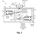
- the wedges 128, 130 have a second position, shown in Fig. 3 , radially pressed against the brake shaft 108 for applying braking forces to the brake shaft 108 and thereby to the generator shaft 104 (labeled in Fig. 1 ), for slowing and stopping rotation of the PMG 102 labeled in Fig. 1 .
- the shear shaft 110 ruptures due to torque applied by the braking forces, then the PMG 102 is brought to zero speed.
- the actuator 116 of the brake system 106 is operatively connected to the wedges 128, 130 to actuate the wedges 128, 130 from the first position (in Fig. 2 ) to the second position (in Fig. 3 ).
- the actuator 116 includes the servo valve 114, which is operatively connected to actuate the wedges 128, 138 between the first and second positions based on commands from the GCU 120 labeled in Fig. 1 .
- the second wedge 130 is radially opposite the first wedge 128 relative to the longitudinal axis A, in other words, the first wedge 128 extends to the left of the shaft 108 and the second wedge 130 extends to the right as oriented in Figs. 2-3 , radially opposite directions from the longitudinal axis A.
- the first wedge 128 contacts a position P1 on the brake shaft 108 that is diametrically opposed to a position P2 on the brake shaft 108 where the second wedge 130 contacts the brake shaft 108, relative to the longitudinal axis A.
- the PMG 102 (labeled in Fig.
- the brake system 106 includes a housing 132 with a respective backing surface 134, 136 for each of the wedges 128, 130.
- the first and second wedges 128, 130 in their second positions as shown in Fig. 3 are wedged between the respective the respective backing surfaces 134, 136 and the brake shaft 108.
- Each first wedge 128, 130 includes a piston 138 seated in a cylinder 140, e.g. as a glide ring seal, tight clearance, or the like where some leakage may be acceptable.
- the cylinders 140 are each in fluid communication with a control line 142 of the servo valve 114 through a respective conduit 144, e.g. inside the housing 132.
- the servo valve 114 has a first state shown in Fig. 2 allowing a supply from the oil system 118 to flow from an inlet 146 of the servo valve 114 to an outlet 148 of the servo valve 114 to a return of the oil system 118.
- the servo valve 114 has a second state shown in Fig. 3 , connecting pressure from the inlet 146 of the servo valve 114 in fluid communication with the control line 142 for pressurizing the first and second pistons 138 to drive the first and second wedges 128, 130 to their section positions.
- Each cylinder 140 includes a respective biasing member 150, e.g. spring, Bellville washer, complaint mechanism, or the like, which biases the pistons 138 toward the first position shown in Fig. 2 .
- the biasing members 150 are configured to maintain the piston 138 in the first position when there is no pressure supplied from the servo valve 114 to the conduits 144. Pressure supplied from the control line 142 with the servo valve 114 in the second state, shown in Fig. 3 , overcomes the biasing members 150 to move the wedges 128, 130 into the second position. Rotation of the brake shaft 108 pulls the wedges in-between the backing surfaces 134, 136 of the housing 132 and the brake shaft 108, potentially plastically deforming the wedges 128, 130.
- a respective biasing member 150 e.g. spring, Bellville washer, complaint mechanism, or the like, which biases the pistons 138 toward the first position shown in Fig. 2 .
- the biasing members 150 are configured to maintain the piston 138 in the
- Each of the wedges has a respective piston surface 152 in fluid communication with the respective conduit 144, even in the first position. This can be maintained in the first position, e.g. with the standoffs 154 or by having the conduits 155 feed into axial ports onto the surfaces 152.
- systems and methods as disclosed herein can operate by first disconnecting the PMG rotor from the prime mover and second by bringing the rotor to zero speed as quickly as possible.
- a high-speed PMG can be connected to a separate brake system, or the brake system can be integral to the PMG 102.
- the shear shaft 110 ruptures at a specified torque that is be high enough such that it does not rupture during normal operation but does rupture when the brake is applied as described above with reference to Fig. 3 . Once the brake is applied, the shear shaft 110 ruptures, and the PMG 102 is disconnected from the prime mover 112. After this disconnection, the brake system 106 quickly slows the high speed PMG 102 down to zero speed.
- the servo valve 114 is in constant bypass mode as shown in Fig. 2 , where no oil pressure is applied to the pistons 138, i.e. there is zero control pressure.
- the biasing members 150 of Fig. 2 keep the wedges 128, 130 pushed back from the brake shaft 108 and thus not engaged.
- the servo valve 114 is set, e.g. by the GCU 120 to zero bypass mode, where the return port is completely blocked off and flow is directed to pressure the control line 142.
- This control pressure pushes the wedges 128, 130 into the second position shown in Fig. 3 .
- the drag torque created by this wedging ruptures the shear shaft 110 of Fig. 1 .
- the wedges 128, 130 continue to be pulled into the gap between the brake shaft 108 and the housing 132 and quickly bring the rotor of the PMG 102 to zero speed.
Landscapes
- Engineering & Computer Science (AREA)
- Power Engineering (AREA)
- General Engineering & Computer Science (AREA)
- Mechanical Engineering (AREA)
- Microelectronics & Electronic Packaging (AREA)
- Life Sciences & Earth Sciences (AREA)
- Sustainable Development (AREA)
- Sustainable Energy (AREA)
- Chemical & Material Sciences (AREA)
- Combustion & Propulsion (AREA)
- Connection Of Motors, Electrical Generators, Mechanical Devices, And The Like (AREA)
- Braking Arrangements (AREA)
Abstract
Description
- The present disclosure relates to power generation, and more particularly to brakes for permanent magnet generators (PMGs) such as used with gas turbine engines to generate electrical power.
- Wound field synchronous machine type generators have been used for power generation aboard aircraft with prime mover power input from the aircraft engine, e.g. gas turbine engines. Permanent magnet generators (PMGs) offer various operation advantages over synchronous field generators. However PMGs introduce a novel issue as synchronous machine type generators can simply be de-excited to stop feeding a fault in a very short time.
- In a permanent magnet generator, any time the rotor is spinning, a voltage is being applied to the stator. If a short circuit fault occurs in the stator, the fault will continue to be active until the generator is at zero speed. Permanent magnet machines cannot be de-excited, they must be brought to zero speed to stop feeding the fault. This is particularly challenging because PMGs can spin two to five times faster than traditional would field synchronous machines.
- The conventional techniques have been considered satisfactory for their intended purpose. However, there is an ever present need for improved systems and methods for PMG braking, e.g. in conjunction with aircraft engines. This disclosure provides a solution for this need.
- A system includes a permanent magnet generator (PMG) with a generator shaft defining a longitudinal axis. A brake system includes a brake shaft with a first end operatively connected to the generator shaft for selectively rotating with the generator shaft or braking to slow the generator shaft. A shear shaft is operatively connected to a second end of the brake shaft axially opposite the first end along the longitudinal axis. The shear shaft is configured for connection to a prime mover for rotation of the generator shaft, and is configured to rotate together with the prime mover and with the brake shaft under normal conditions, and to disconnect the prime mover from the brake shaft if subjected to a predetermined torque. The brake system includes a wedge with a first position radially withdrawn from the brake shaft, and a second position radially pressed against the brake shaft for applying braking forces to the brake shaft and to the generator shaft, wherein the brake system includes an actuator operatively connected to the wedge to actuate the wedge from the first position to the second position.
- A second wedge can have a first position radially withdrawn from the brake shaft, and a second position radially pressed against the brake shaft for applying braking forces to the brake shaft and to the generator shaft. The actuator can be operatively connected to the second wedge to actuate the first and second wedges together between the first and second positions of the first and second wedges. The second wedge can be radially opposite the first wedge relative to the longitudinal axis. In the second position of the first and second wedges, the first wedge can contact a position on the brake shaft that is diametrically opposed to a position on the brake shaft where the second wedge contacts the brake shaft, relative to the longitudinal axis. The PMG can be configured to be driven in a rotational direction, and the first and second wedges can be oriented so that contact with the brake shaft urges the wedges toward the brake shaft due to the rotation direction of the PMG. The brake system can include a housing with a respective backing surface. The first and second wedges in their second positions can be wedged between the respective backing surface and the brake shaft.
- The actuator can include a servo valve. The first wedge can include a first piston seated in a cylinder. The second wedge can include a second piston seated in a second cylinder. The first cylinder can be in fluid communication with a control line of the servo valve through a first conduit. The second cylinder can be in fluid communication with the control line through a second conduit. The servo valve can have a first state allowing a supply to flow from an inlet of the servo valve to an outlet of the servo valve to a return, and a second state connecting pressure from the inlet of the servo valve in fluid communication with the control line for pressurizing the first and second pistons to drive the first and second wedges to their section positions.
- A first biasing member can bias the first piston toward the first position, wherein the first biasing member is configured to maintain the first piston in the first position with no pressure supplied from the servo valve. A second biasing member can bias the second piston toward the first position, wherein the second biasing member is configured to maintain the second piston in the first position with no pressure supplied from the servo valve. The first wedge can have a piston surface in fluid communication with the first conduit in the first position, and the second wedge can have a piston surface in fluid communication with the second conduit in the first position.
- A gas turbine engine (GTE) can be operatively connected to the shear shaft to drive the PMG as a prime mover. A servo valve can be operatively connected to actuate the wedge between the first and second positions. The servo valve can be a hydraulic servo connected to an oil system that provides oil to the PMG and/or to the GTE.
- A generator control unit (GCU) can be operatively connected to the PMG for controlling electrical output of the PMG. The GCU can be operatively connected to the servo valve, which can be operatively connected to actuate the wedge based on commands from the GCU. A sensor can be operatively connected to the GCU to provide feedback for controlling the brake system. The sensor can include a speed sensor operatively connected to provide feedback to the GCU indicative of speed of the generator shaft. The sensor can include a voltage sensor operatively connected to a voltage output of the PMG to generate feedback to the GCU indicative of voltage output of the PMG. The GCU can be configured to output servo current to the servo valve for control of braking of the generator shaft. The GCU can include machine readable instructions configured to cause the GCU to receive input indicative of a fault condition for the PMG, and enter into a braking mode based on the input indicative of the fault condition; and output a command to a servo valve for dynamic control of the brake system for dynamically applying braking to the generator shaft.
- These and other features of the systems and methods of the subject disclosure will become more readily apparent to those skilled in the art from the following detailed description of the preferred embodiments taken in conjunction with the drawings.
- So that those skilled in the art to which the subject disclosure appertains will readily understand how to make and use the devices and methods of the subject disclosure without undue experimentation, preferred embodiments thereof will be described in detail herein below with reference to certain figures, wherein:
-
Fig. 1 is a schematic view of an embodiment of a system constructed in accordance with the present disclosure, showing the brake system between the permanent magnet generator (PMG) and the gas turbine engine (GTE); -
Fig. 2 is a schematic view of the system ofFig. 1 , showing the wedges of the brake system in the first position for normal operation of the PMG; and -
Fig. 3 is a schematic view of the system ofFig. 1 , showing the wedges of the brake system in the second position for braking. - Reference will now be made to the drawings wherein like reference numerals identify similar structural features or aspects of the subject disclosure. For purposes of explanation and illustration, and not limitation, a partial view of an embodiment of a system in accordance with the disclosure is shown in
Fig. 1 and is designated generally byreference character 100. Other embodiments of systems in accordance with the disclosure, or aspects thereof, are provided inFigs. 2-3 , as will be described. The systems and methods described herein can be used to provide protection against main stator arcing events for permanent magnet generator (PMG) systems such as used with aircraft engines and the like. - The
system 100 includes a permanent magnet generator (PMG) 102, e.g. a high speed PMG for power generation on an aircraft, with agenerator shaft 104 defining a longitudinal axis A. Abrake system 106 includes abrake shaft 108 with a first end operatively connected to thegenerator shaft 104, e.g. with a spline, for selectively rotating with thegenerator shaft 104 or braking to slow thegenerator shaft 104. - A
shear shaft 110 is operatively connected, e.g. with a spline or the like, to a second end of thebrake shaft 108 axially opposite the first end along the longitudinal axis A. Theshear shaft 110 is configured for connection to theprime mover 112 for rotation of the generator shaft, and is configured to rotate together with the prime mover and with thebrake shaft 108 under normal conditions. Theshear shaft 110 is configured to disconnect theprime mover 112 from thebrake shaft 108 if subjected a predetermined torque differential between the prime mover and the brake shaft, i.e. when the brake is applied as described below. The shear shaft can include a necking down, frangible structure, burstable structure, or the like, designed to break or burst at the predetermined torque. - With continued reference to
Fig. 1 , theactuator 116 of thebrake system 100 includes aservo valve 114. Theprime mover 112 is a gas turbine engine (GTE) that operatively connected to theshear shaft 110 to drive thePMG 102. Theservo valve 114 is a hydraulic servo connected to anoil system 118 that provides oil to thePMG 102 and/or to the GTE for cooling and/or lubrication. Theoil system 118 provides actuating oil to theservo valve 114 for use in actuating thebraking system 100 as described below. - A generator control unit (GCU) 120 is operatively connected to the
PMG 102 for controlling electrical output of thePMG 102. TheGCU 120 is operatively connected to theservo valve 114, which is operatively connected to actuate thebrake system 106 based on commands from theGCU 120. Asensor 122 is operatively connected to theGCU 120 to provide feedback for controlling thebrake system 106. Thesensor 122 includes a voltage, current, and/or electrical fault sensor operatively connected to the output of thePMG 102 to generate feedback to theGCU 120 indicative of electrical output of thePMG 102 and/or a fault in thePMG 102. It is also contemplated that in addition to or in lieu of thesensor 122, asensor 124 can be a speed sensor operatively connected to provide feedback to theGCU 120 indicative of speed of thegenerator shaft 104, or thePMG 102 itself can be used as a speed sensor. TheGCU 120 is configured to output servo current to theservo valve 114 for control of braking of thegenerator shaft 104. - With continued reference to
Fig. 1 , theGCU 120 includes machine readable instructions, e.g. digital code, digital logic components, analog circuitry, and/or the like, configured to cause theGCU 120 to receive input, e.g. from thesensors PMG 120, e.g. a main stator short, whereinPMG 120 needs to be stopped, and enter into a braking mode based on the input indicative of the fault condition; and output a command, e.g. servo current, to theservo valve 114 for dynamic control of thebrake system 106 for dynamically applying braking to thegenerator shaft 104. - With reference now to
Figs. 2-3 , thebrake system 106 includes afirst wedge 128 and asecond wedge 130. The first and second wedges have a first position, shown inFig. 2 that is radially withdrawn from thebrake shaft 108 for normal operation of the PMG 102 (labeled inFig. 1 ). Thewedges Fig. 3 , radially pressed against thebrake shaft 108 for applying braking forces to thebrake shaft 108 and thereby to the generator shaft 104 (labeled inFig. 1 ), for slowing and stopping rotation of thePMG 102 labeled inFig. 1 . Theshear shaft 110 ruptures due to torque applied by the braking forces, then thePMG 102 is brought to zero speed. - The
actuator 116 of thebrake system 106 is operatively connected to thewedges wedges Fig. 2 ) to the second position (inFig. 3 ). Theactuator 116 includes theservo valve 114, which is operatively connected to actuate thewedges GCU 120 labeled inFig. 1 . - The
second wedge 130 is radially opposite thefirst wedge 128 relative to the longitudinal axis A, in other words, thefirst wedge 128 extends to the left of theshaft 108 and thesecond wedge 130 extends to the right as oriented inFigs. 2-3 , radially opposite directions from the longitudinal axis A. In the second position of the first andsecond wedges Fig. 3 , thefirst wedge 128 contacts a position P1 on thebrake shaft 108 that is diametrically opposed to a position P2 on thebrake shaft 108 where thesecond wedge 130 contacts thebrake shaft 108, relative to the longitudinal axis A. The PMG 102 (labeled inFig. 1 ) is configured to be driven in a rotational direction indicated by the rotation arrow inFigs. 2-3 . The first andsecond wedges rotating brake shaft 108 urges thewedges brake shaft 108 due to the rotation direction of the PMG 102 (labeled inFig. 1 ). Thebrake system 106 includes ahousing 132 with arespective backing surface wedges second wedges Fig. 3 are wedged between the respective the respective backing surfaces 134, 136 and thebrake shaft 108. - Each
first wedge piston 138 seated in acylinder 140, e.g. as a glide ring seal, tight clearance, or the like where some leakage may be acceptable. Thecylinders 140 are each in fluid communication with acontrol line 142 of theservo valve 114 through arespective conduit 144, e.g. inside thehousing 132. Theservo valve 114 has a first state shown inFig. 2 allowing a supply from theoil system 118 to flow from aninlet 146 of theservo valve 114 to anoutlet 148 of theservo valve 114 to a return of theoil system 118. Theservo valve 114 has a second state shown inFig. 3 , connecting pressure from theinlet 146 of theservo valve 114 in fluid communication with thecontrol line 142 for pressurizing the first andsecond pistons 138 to drive the first andsecond wedges - Each
cylinder 140 includes arespective biasing member 150, e.g. spring, Bellville washer, complaint mechanism, or the like, which biases thepistons 138 toward the first position shown inFig. 2 . The biasingmembers 150 are configured to maintain thepiston 138 in the first position when there is no pressure supplied from theservo valve 114 to theconduits 144. Pressure supplied from thecontrol line 142 with theservo valve 114 in the second state, shown inFig. 3 , overcomes the biasingmembers 150 to move thewedges brake shaft 108 pulls the wedges in-between the backing surfaces 134, 136 of thehousing 132 and thebrake shaft 108, potentially plastically deforming thewedges respective piston surface 152 in fluid communication with therespective conduit 144, even in the first position. This can be maintained in the first position, e.g. with thestandoffs 154 or by having the conduits 155 feed into axial ports onto thesurfaces 152. - With reference again to
Fig. 1 , systems and methods as disclosed herein can operate by first disconnecting the PMG rotor from the prime mover and second by bringing the rotor to zero speed as quickly as possible. A high-speed PMG can be connected to a separate brake system, or the brake system can be integral to thePMG 102. Theshear shaft 110 ruptures at a specified torque that is be high enough such that it does not rupture during normal operation but does rupture when the brake is applied as described above with reference toFig. 3 . Once the brake is applied, theshear shaft 110 ruptures, and thePMG 102 is disconnected from theprime mover 112. After this disconnection, thebrake system 106 quickly slows thehigh speed PMG 102 down to zero speed. - Under normal operating conditions, the
servo valve 114 is in constant bypass mode as shown inFig. 2 , where no oil pressure is applied to thepistons 138, i.e. there is zero control pressure. The biasingmembers 150 ofFig. 2 keep thewedges brake shaft 108 and thus not engaged. - Under a main stator failure in the
PMG 102, for example, theservo valve 114 is set, e.g. by theGCU 120 to zero bypass mode, where the return port is completely blocked off and flow is directed to pressure thecontrol line 142. This control pressure pushes thewedges Fig. 3 . The drag torque created by this wedging ruptures theshear shaft 110 ofFig. 1 . After the rupture occurs, thewedges brake shaft 108 and thehousing 132 and quickly bring the rotor of thePMG 102 to zero speed. - The methods and systems of the present disclosure, as described above and shown in the drawings, provide for main stator arcing protection for PMG systems such as used with aircraft engines and the like. While the apparatus and methods of the subject disclosure have been shown and described with reference to preferred embodiments, those skilled in the art will readily appreciate that changes may be made thereto without departing from the scope of the invention as defined by the claims.
Claims (15)
- A system comprising:a permanent magnet generator, PMG, (102) with a generator shaft (104) defining a longitudinal axis;a brake system (106), wherein the brake system includes a brake shaft (108) with a first end operatively connected to the generator shaft for selectively rotating with the generator shaft or braking to slow the generator shaft; anda shear shaft (110) operatively connected to a second end of the brake shaft axially opposite the first end along the longitudinal axis, the shear shaft being configured for connection to a prime mover (112) for rotation of the generator shaft, and being configured to rotate together with the prime mover and with the brake shaft under normal conditions, and to disconnect the prime mover from the brake shaft if subjected to a predetermined torque;wherein the brake system includes a wedge (128) with a first position radially withdrawn from the brake shaft, and a second position radially pressed against the brake shaft for applying braking forces to the brake shaft and to the generator shaft, wherein the brake system includes an actuator (116) operatively connected to the wedge to actuate the wedge from the first position to the second position.
- The system as recited in claim 1, wherein the wedge is a first wedge (128) and further comprising a second wedge (130) with a first position radially withdrawn from the brake shaft, and a second position radially pressed against the brake shaft for applying braking forces to the brake shaft and to the generator shaft, wherein the actuator is operatively connected to the second wedge to actuate the first and second wedges together between the first and second positions of the first and second wedges.
- The system as recited in claim 2, wherein the second wedge is radially opposite the first wedge relative to the longitudinal axis.
- The system as recited in claim 2, wherein in the second position of the first and second wedges, the first wedge contacts a position on the brake shaft that is diametrically opposed to a position on the brake shaft where the second wedge contacts the brake shaft, relative to the longitudinal axis.
- The system as recited in claim 4, wherein the PMG is configured to be driven in a rotational direction, wherein the first and second wedges are oriented so that contact with the brake shaft urges the wedges toward the brake shaft due to the rotation direction of the PMG.
- The system as recited in claim 5, wherein the brake system includes a housing (132) with a respective backing surface (134, 136), wherein the first and second wedges in their second positions are wedged between the respective backing surface and the brake shaft.
- The system as recited in claim 2, wherein the actuator includes a servo valve (114), wherein the first wedge includes a first piston (138) seated in a cylinder (140), wherein the second wedge includes a second piston seated in a second cylinder, wherein the first cylinder is in fluid communication with a control line of the servo valve through a first conduit (144), wherein the second cylinder is in fluid communication with the control line through a second conduit, and wherein the servo valve has a first state allowing a supply to flow from an inlet of the servo valve to an outlet of the servo valve to a return, and a second state connecting pressure from the inlet of the servo valve in fluid communication with the control line for pressurizing the first and second pistons to drive the first and second wedges to their section positions.
- The system as recited in claim 7, further comprising:a first biasing member (150) biasing the first piston toward the first position, wherein the first biasing member is configured to maintain the first piston in the first position with no pressure supplied from the servo valve; anda second biasing member biasing the second piston toward the first position, wherein the second biasing member is configured to maintain the second piston in the first position with no pressure supplied from the servo valve, and optionally wherein the first wedge has a piston surface (152) in fluid communication with the first conduit in the first position, and wherein the second wedge has a piston surface in fluid communication with the second conduit in the first position.
- The system as recited in claim 1, further comprising a gas turbine engine, GTE, operatively connected to the shear shaft to drive the PMG as a prime mover.
- The system as recited in claim 9, further comprising a servo valve operatively connected to actuate the wedge between the first and second positions, wherein the servo valve is a hydraulic servo connected to an oil system that provides oil to the PMG and/or to the GTE.
- The system as recited in claim 1, further comprising a generator control unit, GCU, (120) operatively connected to the PMG for controlling electrical output of the PMG.
- The system as recited in claim 11, wherein the GCU is operatively connected to a servo valve, which is operatively connected to actuate the wedge based on commands from the GCU.
- The system as recited in claim 12, further comprising a sensor (122) operatively connected to the GCU to provide feedback for controlling the brake system., and optionally: wherein the sensor includes a speed sensor (124) operatively connected to provide feedback to the GCU indicative of speed of the generator shaft and/or wherein the sensor includes a voltage sensor operatively connected to a voltage output of the PMG to generate feedback to the GCU indicative of voltage output of the PMG.
- The system as recited in claim 13, wherein the GCU is configured to output servo current to the servo valve for control of braking of the generator shaft.
- The system as recited in any of claims 11 to 14, wherein the GCU includes machine readable instructions configured to cause the GCU to:receive input indicative of a fault condition for the PMG, and enter into a braking mode based on the input indicative of the fault condition; andoutput a command to a servo valve for dynamic control of the brake system for dynamically applying braking to the generator shaft.
Applications Claiming Priority (1)
| Application Number | Priority Date | Filing Date | Title |
|---|---|---|---|
| US18/105,416 US12160156B2 (en) | 2023-02-03 | 2023-02-03 | Permanent magnet generator brakes with dual wedges |
Publications (2)
| Publication Number | Publication Date |
|---|---|
| EP4425765A1 true EP4425765A1 (en) | 2024-09-04 |
| EP4425765B1 EP4425765B1 (en) | 2026-04-29 |
Family
ID=89833755
Family Applications (1)
| Application Number | Title | Priority Date | Filing Date |
|---|---|---|---|
| EP24155365.0A Active EP4425765B1 (en) | 2023-02-03 | 2024-02-01 | Permanent magnet generator brakes with dual wedges |
Country Status (2)
| Country | Link |
|---|---|
| US (1) | US12160156B2 (en) |
| EP (1) | EP4425765B1 (en) |
Families Citing this family (2)
| Publication number | Priority date | Publication date | Assignee | Title |
|---|---|---|---|---|
| FR3086325B1 (en) * | 2018-09-24 | 2020-11-20 | Safran Aircraft Engines | AUXILIARY OIL TANK FOR AN AIRCRAFT TURBOMACHINE |
| US12510002B2 (en) * | 2023-07-12 | 2025-12-30 | General Electric Company | Lubrication system for a turbine engine |
Citations (6)
| Publication number | Priority date | Publication date | Assignee | Title |
|---|---|---|---|---|
| JPS5270278A (en) * | 1975-12-08 | 1977-06-11 | Susumu Sasa | Simple type brake |
| JP2000325172A (en) * | 1999-05-18 | 2000-11-28 | Toyota Motor Corp | Reclining mechanism |
| EP2526313B1 (en) * | 2010-01-21 | 2015-03-18 | Schaeffler Technologies AG & Co. KG | Bearing capable of being braked |
| US20200096062A1 (en) * | 2018-09-21 | 2020-03-26 | Rolls-Royce Corporation | Hydraulic brake and disconnect for rotational machines |
| US20200099322A1 (en) * | 2018-09-21 | 2020-03-26 | Rolls-Royce Corporation | Hydraulic braking and power extraction for rotational machines |
| CN213230903U (en) * | 2020-07-28 | 2021-05-18 | 威海银兴预应力线材有限公司 | Pay-off is used in production of high-speed railway prestressing force steel strand wires |
Family Cites Families (9)
| Publication number | Priority date | Publication date | Assignee | Title |
|---|---|---|---|---|
| US5300848A (en) * | 1989-11-14 | 1994-04-05 | Sunstrand Corporation | Dual permanent magnet generator planetary gear actuator and rotor phase shifting method |
| US6455975B1 (en) * | 1999-12-03 | 2002-09-24 | Pacific Scientific Electro Kinetics Division | Regulated permanent magnet generator |
| US20080078631A1 (en) * | 2004-02-05 | 2008-04-03 | Erlston Lester J | Disc brake in combination with brushless electric motor-generator |
| GB0412203D0 (en) * | 2004-06-01 | 2004-07-07 | Goodrich Control Sys Ltd | Disconnect mechanism and devices including such a disconnect mechanism |
| US7849668B2 (en) | 2006-10-25 | 2010-12-14 | United Technologies Corporation | Rotor brake and windmilling lubrication system for geared turbofan engine |
| DK2333326T3 (en) * | 2009-11-26 | 2013-08-12 | Siemens Ag | Brake system for a wind turbine with integrated rotor lock, generator and wind turbine |
| EP2479427A1 (en) * | 2011-01-24 | 2012-07-25 | Siemens Aktiengesellschaft | Method for attenuating the oscillation of a power train in a wind turbine, wind turbine and use of a braking device |
| US9748816B2 (en) * | 2014-03-21 | 2017-08-29 | Regal Beloit America, Inc. | Axial flux electric machine including an integral brake and methods of assembling the same |
| US20200220439A1 (en) * | 2016-12-30 | 2020-07-09 | Axel Michael Sigmar | Integrated Adaptive Polyphase Electric Motor |
-
2023
- 2023-02-03 US US18/105,416 patent/US12160156B2/en active Active
-
2024
- 2024-02-01 EP EP24155365.0A patent/EP4425765B1/en active Active
Patent Citations (6)
| Publication number | Priority date | Publication date | Assignee | Title |
|---|---|---|---|---|
| JPS5270278A (en) * | 1975-12-08 | 1977-06-11 | Susumu Sasa | Simple type brake |
| JP2000325172A (en) * | 1999-05-18 | 2000-11-28 | Toyota Motor Corp | Reclining mechanism |
| EP2526313B1 (en) * | 2010-01-21 | 2015-03-18 | Schaeffler Technologies AG & Co. KG | Bearing capable of being braked |
| US20200096062A1 (en) * | 2018-09-21 | 2020-03-26 | Rolls-Royce Corporation | Hydraulic brake and disconnect for rotational machines |
| US20200099322A1 (en) * | 2018-09-21 | 2020-03-26 | Rolls-Royce Corporation | Hydraulic braking and power extraction for rotational machines |
| CN213230903U (en) * | 2020-07-28 | 2021-05-18 | 威海银兴预应力线材有限公司 | Pay-off is used in production of high-speed railway prestressing force steel strand wires |
Also Published As
| Publication number | Publication date |
|---|---|
| EP4425765B1 (en) | 2026-04-29 |
| US20240266911A1 (en) | 2024-08-08 |
| US12160156B2 (en) | 2024-12-03 |
Similar Documents
| Publication | Publication Date | Title |
|---|---|---|
| EP4425765B1 (en) | Permanent magnet generator brakes with dual wedges | |
| US11387706B2 (en) | Generator having a disconnect mechanism | |
| CN107531140B (en) | Powertrain and method of starting the powertrain | |
| US8378510B2 (en) | Starting and generating apparatus for engine | |
| EP3746669B1 (en) | Aircraft engine generator disconnect device | |
| EP4118353B1 (en) | Generator coupling system | |
| US6260667B1 (en) | Rotor containment brake | |
| US20230184306A1 (en) | System and method to disconnect and brake a rotating device | |
| EP4425766A1 (en) | Permanent motor generator band brakes | |
| US8430630B2 (en) | Rotary coupling | |
| EP4407845A1 (en) | Turbogenerator brakes | |
| US12149151B2 (en) | Permanent magnet generator brakes with press slip fit | |
| GB2634510A (en) | Disconnect arrangement with actuation device | |
| EP2048398A2 (en) | A Drive Transfer and Disconnect Device | |
| CN120641674A (en) | Assembly for aircraft propulsion assembly, achieving detachable coupling of two shafts by coupling sleeves actuated by pressurized fluid | |
| Talbot | Hazards of Reverse Pump Rotation | |
| CN118855636A (en) | A wind turbine generator set yaw clearance elimination control method and system |
Legal Events
| Date | Code | Title | Description |
|---|---|---|---|
| PUAI | Public reference made under article 153(3) epc to a published international application that has entered the european phase |
Free format text: ORIGINAL CODE: 0009012 |
|
| STAA | Information on the status of an ep patent application or granted ep patent |
Free format text: STATUS: THE APPLICATION HAS BEEN PUBLISHED |
|
| AK | Designated contracting states |
Kind code of ref document: A1 Designated state(s): AL AT BE BG CH CY CZ DE DK EE ES FI FR GB GR HR HU IE IS IT LI LT LU LV MC ME MK MT NL NO PL PT RO RS SE SI SK SM TR |
|
| STAA | Information on the status of an ep patent application or granted ep patent |
Free format text: STATUS: REQUEST FOR EXAMINATION WAS MADE |
|
| 17P | Request for examination filed |
Effective date: 20250304 |
|
| STAA | Information on the status of an ep patent application or granted ep patent |
Free format text: STATUS: EXAMINATION IS IN PROGRESS |
|
| 17Q | First examination report despatched |
Effective date: 20250424 |
|
| GRAP | Despatch of communication of intention to grant a patent |
Free format text: ORIGINAL CODE: EPIDOSNIGR1 |
|
| STAA | Information on the status of an ep patent application or granted ep patent |
Free format text: STATUS: GRANT OF PATENT IS INTENDED |
|
| INTG | Intention to grant announced |
Effective date: 20251212 |
|
| GRAS | Grant fee paid |
Free format text: ORIGINAL CODE: EPIDOSNIGR3 |
|
| GRAA | (expected) grant |
Free format text: ORIGINAL CODE: 0009210 |
|
| STAA | Information on the status of an ep patent application or granted ep patent |
Free format text: STATUS: THE PATENT HAS BEEN GRANTED |
|
| AK | Designated contracting states |
Kind code of ref document: B1 Designated state(s): AL AT BE BG CH CY CZ DE DK EE ES FI FR GB GR HR HU IE IS IT LI LT LU LV MC ME MK MT NL NO PL PT RO RS SE SI SK SM TR |
|
| REG | Reference to a national code |
Ref country code: CH Ref legal event code: F10 Free format text: ST27 STATUS EVENT CODE: U-0-0-F10-F00 (AS PROVIDED BY THE NATIONAL OFFICE) Effective date: 20260429 Ref country code: GB Ref legal event code: FG4D |