EP4425722A1 - Plug arrangement - Google Patents
Plug arrangement Download PDFInfo
- Publication number
- EP4425722A1 EP4425722A1 EP24160258.0A EP24160258A EP4425722A1 EP 4425722 A1 EP4425722 A1 EP 4425722A1 EP 24160258 A EP24160258 A EP 24160258A EP 4425722 A1 EP4425722 A1 EP 4425722A1
- Authority
- EP
- European Patent Office
- Prior art keywords
- plug
- blocking
- pivoting lever
- mating
- blocking element
- Prior art date
- Legal status (The legal status is an assumption and is not a legal conclusion. Google has not performed a legal analysis and makes no representation as to the accuracy of the status listed.)
- Pending
Links
Images



Classifications
-
- H—ELECTRICITY
- H01—ELECTRIC ELEMENTS
- H01R—ELECTRICALLY-CONDUCTIVE CONNECTIONS; STRUCTURAL ASSOCIATIONS OF A PLURALITY OF MUTUALLY-INSULATED ELECTRICAL CONNECTING ELEMENTS; COUPLING DEVICES; CURRENT COLLECTORS
- H01R13/00—Details of coupling devices of the kinds covered by groups H01R12/70 or H01R24/00 - H01R33/00
- H01R13/62—Means for facilitating engagement or disengagement of coupling parts or for holding them in engagement
- H01R13/629—Additional means for facilitating engagement or disengagement of coupling parts, e.g. aligning or guiding means, levers, gas pressure electrical locking indicators, manufacturing tolerances
- H01R13/62933—Comprising exclusively pivoting lever
- H01R13/62938—Pivoting lever comprising own camming means
-
- H—ELECTRICITY
- H01—ELECTRIC ELEMENTS
- H01R—ELECTRICALLY-CONDUCTIVE CONNECTIONS; STRUCTURAL ASSOCIATIONS OF A PLURALITY OF MUTUALLY-INSULATED ELECTRICAL CONNECTING ELEMENTS; COUPLING DEVICES; CURRENT COLLECTORS
- H01R13/00—Details of coupling devices of the kinds covered by groups H01R12/70 or H01R24/00 - H01R33/00
- H01R13/62—Means for facilitating engagement or disengagement of coupling parts or for holding them in engagement
- H01R13/629—Additional means for facilitating engagement or disengagement of coupling parts, e.g. aligning or guiding means, levers, gas pressure electrical locking indicators, manufacturing tolerances
- H01R13/62933—Comprising exclusively pivoting lever
- H01R13/62944—Pivoting lever comprising gear teeth
-
- H—ELECTRICITY
- H01—ELECTRIC ELEMENTS
- H01R—ELECTRICALLY-CONDUCTIVE CONNECTIONS; STRUCTURAL ASSOCIATIONS OF A PLURALITY OF MUTUALLY-INSULATED ELECTRICAL CONNECTING ELEMENTS; COUPLING DEVICES; CURRENT COLLECTORS
- H01R13/00—Details of coupling devices of the kinds covered by groups H01R12/70 or H01R24/00 - H01R33/00
- H01R13/62—Means for facilitating engagement or disengagement of coupling parts or for holding them in engagement
- H01R13/629—Additional means for facilitating engagement or disengagement of coupling parts, e.g. aligning or guiding means, levers, gas pressure electrical locking indicators, manufacturing tolerances
- H01R13/62933—Comprising exclusively pivoting lever
- H01R13/62955—Pivoting lever comprising supplementary/additional locking means
-
- H—ELECTRICITY
- H01—ELECTRIC ELEMENTS
- H01R—ELECTRICALLY-CONDUCTIVE CONNECTIONS; STRUCTURAL ASSOCIATIONS OF A PLURALITY OF MUTUALLY-INSULATED ELECTRICAL CONNECTING ELEMENTS; COUPLING DEVICES; CURRENT COLLECTORS
- H01R13/00—Details of coupling devices of the kinds covered by groups H01R12/70 or H01R24/00 - H01R33/00
- H01R13/62—Means for facilitating engagement or disengagement of coupling parts or for holding them in engagement
-
- H—ELECTRICITY
- H01—ELECTRIC ELEMENTS
- H01R—ELECTRICALLY-CONDUCTIVE CONNECTIONS; STRUCTURAL ASSOCIATIONS OF A PLURALITY OF MUTUALLY-INSULATED ELECTRICAL CONNECTING ELEMENTS; COUPLING DEVICES; CURRENT COLLECTORS
- H01R13/00—Details of coupling devices of the kinds covered by groups H01R12/70 or H01R24/00 - H01R33/00
- H01R13/62—Means for facilitating engagement or disengagement of coupling parts or for holding them in engagement
- H01R13/629—Additional means for facilitating engagement or disengagement of coupling parts, e.g. aligning or guiding means, levers, gas pressure electrical locking indicators, manufacturing tolerances
-
- H—ELECTRICITY
- H01—ELECTRIC ELEMENTS
- H01R—ELECTRICALLY-CONDUCTIVE CONNECTIONS; STRUCTURAL ASSOCIATIONS OF A PLURALITY OF MUTUALLY-INSULATED ELECTRICAL CONNECTING ELEMENTS; COUPLING DEVICES; CURRENT COLLECTORS
- H01R13/00—Details of coupling devices of the kinds covered by groups H01R12/70 or H01R24/00 - H01R33/00
- H01R13/62—Means for facilitating engagement or disengagement of coupling parts or for holding them in engagement
- H01R13/629—Additional means for facilitating engagement or disengagement of coupling parts, e.g. aligning or guiding means, levers, gas pressure electrical locking indicators, manufacturing tolerances
- H01R13/62933—Comprising exclusively pivoting lever
-
- H—ELECTRICITY
- H01—ELECTRIC ELEMENTS
- H01R—ELECTRICALLY-CONDUCTIVE CONNECTIONS; STRUCTURAL ASSOCIATIONS OF A PLURALITY OF MUTUALLY-INSULATED ELECTRICAL CONNECTING ELEMENTS; COUPLING DEVICES; CURRENT COLLECTORS
- H01R13/00—Details of coupling devices of the kinds covered by groups H01R12/70 or H01R24/00 - H01R33/00
- H01R13/62—Means for facilitating engagement or disengagement of coupling parts or for holding them in engagement
- H01R13/629—Additional means for facilitating engagement or disengagement of coupling parts, e.g. aligning or guiding means, levers, gas pressure electrical locking indicators, manufacturing tolerances
- H01R13/62933—Comprising exclusively pivoting lever
- H01R13/62961—Pivoting lever having extendable handle
-
- H—ELECTRICITY
- H01—ELECTRIC ELEMENTS
- H01R—ELECTRICALLY-CONDUCTIVE CONNECTIONS; STRUCTURAL ASSOCIATIONS OF A PLURALITY OF MUTUALLY-INSULATED ELECTRICAL CONNECTING ELEMENTS; COUPLING DEVICES; CURRENT COLLECTORS
- H01R13/00—Details of coupling devices of the kinds covered by groups H01R12/70 or H01R24/00 - H01R33/00
- H01R13/62—Means for facilitating engagement or disengagement of coupling parts or for holding them in engagement
- H01R13/639—Additional means for holding or locking coupling parts together, after engagement, e.g. separate keylock, retainer strap
Definitions
- the invention relates to a plug arrangement comprising a housing part for a plug which can be plugged together with a mating plug along a plugging direction and a pivoting lever which can be attached to the housing part.
- the pivoting lever can be used, for example, to move the plug relative to the mating plug, such as to press the plug into the mating plug or vice versa. Alternatively or additionally, the pivoting lever can be used to secure the plug to the mating plug.
- pivoting lever can be pivoted from an initial position to an end position in the attached state, wherein the arrangement has a blocking element that can be transferred from a blocking position to a release position, which blocks pivoting of the pivoting lever out of the initial position in the blocking position and releases pivoting of the pivoting lever in the release position.
- the object of the invention is to provide a solution which allows easy assembly and disassembly.
- the blocking element having a driving element which can be actuated by the mating plug and with which the blocking element is transferred by the mating plug into the blocking position.
- This solution has the advantage that when the plug is disconnected from the mating plug, the blocking element can be pulled into the blocking position by the mating plug. When it is subsequently plugged in, there is no need to adjust the pivoting lever. This simplifies assembly and disassembly.
- Transferring the blocking element to the blocking position can take place automatically when the plug is disconnected from the mating plug. With such a configuration, an additional step of manual or mechanical actuation for transfer can be dispensed with.
- the blocking element can be transferred from the release position to the blocking position during disconnection.
- operation can be simplified, since, for example, an additional step is not required to manually transfer the blocking element from the release position to another position, out of which it is then transferred to the blocking position.
- the driving element can be part of a driving mechanism that also includes other elements, for example of the mating plug. Either existing parts or areas of the mating plug can be used in the driving mechanism so that previous mating plugs can continue to be used. In other configurations, specially configured new elements can be present on the mating plug, which are part of the driving mechanism.
- the plug In the initial position, it may be possible to connect the plug to the mating plug, in particular to plug it in or plug it together along a plugging direction.
- the plug In the end position, the plug can be secured to the mating plug, in particular against being pulled apart in the opposite plugging direction.
- the driving element can have form-fit elements that interact with the mating plug.
- form-fit elements acting against the plugging direction can be present on the driving element.
- the mating plug can have (form-fit) mating elements that interact with the form-fit elements on the driving element.
- the form-fit elements can be projections, recesses, stops or latching elements, for example. In particular, these can act against the plugging direction. They can have form-fit surfaces or abutment surfaces that point against the plugging direction. For example, these run perpendicularly to the plugging direction or slightly inclined to a plane that runs perpendicularly to the plugging direction.
- Corresponding mating elements can be present on the mating plug, where the surfaces run in the opposite direction. In particular, the surfaces on the interacting form-fit elements can be at least partially complementary to each other.
- a force fit i.e. that a force acting perpendicularly to the plugging direction between two interacting surfaces is large enough to transfer the blocking element into the blocking position due to the existing friction.
- Another possible principle is driving by sufficiently large magnetic or electrical forces between two interacting elements.
- the driving element can be configured to interact with the mating plug only in the initial position. Outside the initial position, in particular in the end position, the driving element can have no driving effect for the mating plug. For example, form-fit elements can be disengaged.
- the driving element can be specially configured to be automatically activated when the pivoting lever is moved to the initial position, i.e. to achieve a driving effect for the mating plug.
- a form fit can be present in the activated state, i.e. corresponding parts are in engagement with each other.
- the driving element can be configured to be automatically deactivated when the pivoting lever is pivoted out of the initial position and/or transferred to the end position. Deactivated here means that no or insufficient driving effect is achieved for the mating plug.
- there is no corresponding form fit in the activated state i.e. corresponding elements are not in engagement with each other.
- the driving element can also be activated outside the initial position, in particular in all positions of the pivoting lever.
- the driving element can be configured to be deactivated when the blocking element has reached or exceeded the blocking position.
- simple operation is possible.
- the plug can then be easily disconnected from the mating plug. Deactivation can take place automatically when the blocking position is reached. This eliminates the need for manual or mechanical deactivation in an additional step.
- the driving element can be configured to be deactivated when a defined tensile force between the plug and the mating plug is exceeded.
- deactivation can be automatic. Due to this solution, the plug can be easily disconnected from the mating plug by pulling the two apart. As long as the defined pulling force has not yet been reached, the blocking element is driven by the mating plug. When the blocking position is reached or exceeded, the tensile force increases and the driving element is deactivated.
- the size of such a defined tensile force can be specified in national, international, company-internal or other standards.
- the driving element can, for example, be configured such that a defined counterforce is generated as soon as the blocking position is reached or exceeded.
- the counterforce can, for example, be mainly defined by the sliding friction that occurs when the blocking element moves relative to other parts, for example the pivoting lever or the housing part.
- an additional mechanism can take effect, for example a form fit on surfaces that run perpendicularly to the plugging direction or run more or less inclined to the vertical. If, in the latter case, at least one of the surfaces involved is attached to an element that can be deflected perpendicularly to the plugging direction, for example, a deflection perpendicular to the plugging direction can be achieved by applying a correspondingly high force.
- the strength of a force for sufficient deflection of a deflectable element can be varied as desired by selecting the appropriate lengths, thicknesses and widths of the material.
- the angle of inclination of the surfaces can also be adjusted accordingly.
- the blocking element can be movably mounted on the pivoting lever, in particular displaceably mounted.
- Bearing elements can be provided on the blocking element and/or on the pivoting lever for this purpose.
- the bearing elements can be formed for example as projections or recesses, such as strips or grooves.
- the blocking element and the pivoting lever can be separate parts. They can be manufactured separately and then attached to each other. They can be made of different materials, for example to be able to perform the various functions appropriately.
- the blocking element can be guided on the pivoting lever.
- the blocking element and/or the pivoting lever can have rotational or translational, in particular linear, guide elements.
- the blocking element can move with the pivoting lever.
- One of the two parts can be configured such that when the pivoting lever is pivoted, the blocking element is also moved.
- the blocking element can have a securing element that is configured to automatically secure the blocking element to the housing part when the pivoting lever reaches the end position.
- securing means, in particular, securing against unintentional deflection out of the end position.
- the pivoting lever can be indirectly secured to the housing part via the blocking element.
- a securing element can, for example, be a latching element that enables latching with the housing part.
- the securing element can be part of a securing mechanism that either uses existing housing parts or elements or comprises at least one new, specially configured mating element on the housing part.
- the blocking element can be transferred to the blocking position when the pivoting lever is in the end position.
- the blocking element can be transferred to an intermediate position between the blocking position and the release position, where it can be secured or thereby reduce the space required.
- the plug arrangement can have a stopping mechanism that stops the blocking element from being transferred out of the release position, in particular into the blocking position, if the plug is not fully plugged together with the mating plug.
- the stopping mechanism can have a stopping element on the blocking element that can be released by the mating plug. This can be, for example, a latching element that can be deflected by a projection on the mating plug, which stops the transfer when it is not in the deflected state. In the event of an attempted transfer, the stopping element can abut against a mating element that is attached to the pivoting lever, for example.
- the stopping mechanism is preferably configured such that it is possible to transfer the blocking element back to the release position.
- a detaching element with which the securing element is detached by the securing element, can be arranged to be inaccessible in the blocking position. This can prevent unintentional detachment.
- Inaccessible means, in particular, inaccessible to a user or an apparatus. This can be defined, for example, by the fact that the element cannot be reached with a standardized test finger.
- access along a release direction should not be possible in the blocking position.
- the release direction can be defined as the direction along which a force must be exerted on the detaching element in order to detach the securing element.
- the detaching element can only be completely accessible in the release position. In other positions, the detaching element can be at least partially accessible.
- the detaching element is covered by the pivoting lever in the blocking position.
- part of the pivoting lever can cover or shield the detaching element.
- the blocking element can be an extension element for the pivoting lever, at least in the release position. In other positions, in particular the blocking position, there can be no significant extension of the lever length by the blocking element. A factor of maximum 1.1 of the lever length of the pivoting lever cannot be considered a significant extension.
- the lever length can be measured between a pivot axis (such as a central axis of a shaft) and an actuation section and/or an outer end of the pivoting lever.
- One possible configuration of driving is that the blocking element is pulled into the blocking position by the mating plug. This can enable simple and safe power transmission.
- driving can be configured as pressing, i.e. the blocking element is pressed or pushed into the blocking position by the mating plug.
- the plug arrangement can be configured such that the blocking element can be transferred, in particular moved, to the release position by the mating plug. This can be done automatically, for example, when the plug and mating plug are plugged together. As a result, operation is made easier.
- the blocking element can be transferred from the blocking position to the release position by the mating plug.
- the pivoting lever can only be rotationally movable relative to the housing part, but not translationally movable. This can simplify the construction.
- the plug arrangement can additionally comprise at least one housing part of a mating plug.
- the plug arrangement can have a pulling mechanism which pulls the plug towards the mating plug when the pivoting lever is transferred from the initial position to the end position.
- a pulling mechanism can, for example, be configured as a toothed mechanism with gearwheels, gear racks or the like, or as a spiral guide mechanism with a projection and a spiral guide.
- the driving element can also be referred to as a return element, as it returns the blocking element to the blocking position.
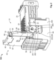
- Figures 1 to 5 show a first embodiment of a plug arrangement 100.
- Fig. 6 a special configuration of a holding mechanism 99 is shown, which can also be used in the first embodiment, for example.
- the plug arrangement 100 comprises in each case a housing part 20 of a plug 120.
- the plug 120 can, for example, be an electrical plug with which power or signals are transmitted.
- further elements may be present on the plug 120, in particular electrical contact elements (not shown).
- the plug 120 shown can thus be connected to a cable and is then used to transmit the power or the signals to a mating plug 200.
- the mating plug 200 shown is configured as a header that can be mounted on a product housing, for example.
- plugs are also possible, for example for the transmission of optical signals, for pneumatic or hydraulic connections or similar. It is also possible to use connectors that are not necessarily plugged in.
- the plug 120 is configured to be plugged together with the mating plug 200 along a plugging direction S.
- the plug 120 is, for example, easily plugged together manually with the mating plug 200.
- the plug arrangement 100 has a pivoting lever 30, which can be attached to the housing part 20.
- the pivoting lever 30 shown can only be moved rotationally relative to the housing part 20, thus pivoted.
- an at least partial translational relative mobility can also be provided, at least in some positions of the pivoting lever 30 relative to the housing part 20.
- the plug arrangement 100 has a pulling mechanism 250, which is configured here as a toothed mechanism 260.
- Teeth 261 which are formed on a gear rack 262 on a housing part 220 of the mating plug 200 and on a gearwheel segment 263 on the pivoting lever 30, engage with one another and convert the pivot movement of the pivoting lever 30 along a pivoting direction L into a translational relative movement. Due to the lever effect, the force required for this, which is applied to an actuation section 37 of the pivoting lever 30, can be relatively low.
- the pivoting lever 30 can be moved, in particular rotated, from an initial position 31 to an end position 32. Pivoting beyond the initial position 31 and the end position 32 can be prevented by the fact that the pivoting lever 30 abuts against stops. In other configurations, however, pivoting beyond the initial position 31 and/or the end position 32 may also be possible.
- pivoting the pivoting lever 30 out of the initial position 31 is only possible if a blocking element 40 is in a release position 42. If, on the other hand, the blocking element 40 is in a blocking position 41, the pivoting lever 30 is blocked from pivoting relative to the housing part 20 by the blocking element 40.
- the blocking element 40 is attached to the pivoting lever 30 and is guided so as to be displaceable relative thereto.
- the blocking position 41 and the release position 42 refer here to a relative position of the pivoting lever 30 to the blocking element 40.
- the blocking effect of the blocking element 40 is achieved here by a form-fit element 43 on the blocking element 40 in the form of a projecting arm 44 engaging in a recess 48 on the housing part 20.
- the blocking element 40 In order to detach the blocking effect 49 achieved by the blocking element 40 and the recess 48, the blocking element 40 is moved in the direction away from a shaft 23 on the housing part 20 on which the pivoting lever 30 is mounted, thus in the example shown against the plugging direction S. This is achieved here by the housing part 220 of the mating plug 200 when it is plugged together with the plug 20. The blocking element 40 is thus automatically transferred to the release position 42 without any special additional action by a user or any apparatus on the blocking element 40.
- the lever length 39 is thereby extended and the force required for pivoting is further minimized. Furthermore, such a configuration has the advantage that in a transport state, as shown for example in Fig. 1 , the lever length 39 is relatively short and thus the risk of damage is reduced.
- the lever length 39 is defined here as the distance between the actuation section 37, which lies between two lever sections 38, and a central axis or axis of rotation of the shaft 23.
- the plug arrangement 100 is already held in a configuration necessary for the plugging process by the blocking mechanism 49. In particular, the pivoting position of the pivoting lever 30 is fixed in the initial position 31.
- a holding mechanism 99 (see, for example, the particularly preferred configuration in Fig. 6 ) can be provided.
- the holding mechanism 99 has a holding element 95 formed integrally with the rest of the blocking element 40, which in particular has an outwardly projecting and elastically inwardly deflectable projection 97, which can latch with a recess 96 and a projection 97 on the rotating lever or pivoting lever 30.
- the blocking effect is automatically canceled by the holding mechanism 99 if a force applied by the mating plug 20 and acting on the blocking element 40 exceeds a certain threshold.
- the projection 95 is then elastically deflected and disengages from the projection 97.
- the pivoting lever 30 is now pivoted from the initial position 31 along a direction of rotation D to the end position 32, which is offset by 90 degrees, it lies flat on the housing part 20.
- the pivoting lever 30 is automatically fixed relative to the housing part 20 by a securing mechanism 79. This is achieved by a securing element 70 in the form of a latching element 71 on the blocking element 40 latching with a corresponding element 75 on the housing part 20. Both are configured as form-fit elements 74, 76 and achieve a form-fit between blocking element 40 and housing part 20 in the latched state. Due to the fact that the blocking element 40 in this state is only displaceable along a transverse direction Q1 parallel to an upper side of the housing 20 relative to the pivoting lever 30, the pivoting lever 30 is thereby indirectly fastened to the housing part 20.
- the securing element 70 on the blocking element 40 is configured as a projection 73, which projects inwards from an arm 72 towards the housing 20.
- the element 75 on the housing part 20 is configured as a ledge 77, so that movement of the securing element 70 and thus of the blocking element 40 along the first transverse direction Q1 parallel to the upper side of the housing 20 is possible.
- the blocking element 40 can therefore be transferred back out of the release position 42 into the blocking position 41.
- a stopping mechanism 94 is deactivated by the housing part 220 of the mating plug 20. Activation is effected by a projection 91 on the housing part 220, which projects through the housing part 20 of the plug 120 and elastically deflects a stopping element 90 on the blocking element 40 only when the plug 120 is fully plugged together with the mating plug 200 (here specifically the housing parts 20 and 220).
- the stopping element 90 here also comprises a projection 92, which projects from an elastically deflectable arm 93. The stopping element 90 is again integral with the rest of the blocking element 40.
- an easy transfer back to a stopping position can be achieved by providing an inclined overrun slope on a side opposite a stopping side.
- the stopping element 90 of the stopping mechanism 94 can simultaneously function as the holding element 95 of the holding mechanism 99. This reduces the complexity and weight and enables simple manufacture.
- a detaching element 80 is provided on the blocking element 40.
- This is configured as a pusher 81, in which pressing along a release direction L, which here runs perpendicularly to the upper side of the housing part 20, is converted into a detaching movement on the securing surface 70.
- the detaching element 80 is connected integrally with the securing element 70 and the rest of the blocking element 40. A bearing that allows sufficient mobility is achieved by thin material bridges 82.
- the blocking element 40 is already in the blocking position 41.
- the detaching element 80 is covered by the transparently shown pivoting lever 30. It is therefore not accessible to a user.
- a signal part 87 is visible to the user through an opening 88 on the pivoting lever 30, so that the user (or a suitable apparatus) can recognize that a complete plugging with a securing device is present.
- the disconnection of the plug 120 from the mating plug 200 takes place in the reverse order, i.e. from Fig. 3 to Fig. 2 and then to Fig. 1 .
- the blocking element 40 is moved relative to the pivoting lever 30 into the release position 42.
- the detaching element 80 By actuating the detaching element 80, the form fit between the locking element 40 and the housing part 20 is canceled, whereby the pivoting lever 30 can be moved back from the end position 32 against the first transverse direction Q1 to the initial position 31.
- the plug arrangement 100 shown here advantageously also comprises a driving mechanism 59, with which the blocking element 40 is automatically transferred by the mating plug 200 from the release position 42 back to the blocking position 41 when the pivoting lever 30 is in the initial position 31 and the mating plug 202 is disconnected or unplugged from the plug 120.
- the driving mechanism 59 is only active in the initial position 31 of the pivoting lever 30. Outside the initial position 31, in particular in the end position 32, the driving mechanism 59 is deactivated.
- the driving mechanism 59 is again based on a form-fit principle.
- a driving element 50 on the blocking element 40 engages in a form-fit manner in a recess 62 on the housing part 220 of the mating plug 200.
- An upper boundary of the recess 62 forms a mating element 61 for the driving element 50.
- the driving element 50 as well as the mating element 61 comprise an arm 52 or 63.
- a latching projection 53 of the driving element 50 serves as a form-fit element 54, which interacts with a form-fit element 65 on the housing 21 of the mating plug 200.
- the embodiment shown is configured such that the driving mechanism 59 is automatically deactivated, i.e. in this case the form-fit elements 54, 65 are disengaged when the blocking position 41 is reached.
- the driving mechanism 59 is automatically deactivated, i.e. in this case the form-fit elements 54, 65 are disengaged when the blocking position 41 is reached.
- a surface 55 on the form-fit elements 54 does not extend completely perpendicularly to the direction of the relative movement between the blocking element 40 and housing part 220, which is restricted by corresponding guide elements. Rather, the surface 55, which interacts with a surface 66 on the mating element 61 in the latched state, is slightly inclined to a plane that runs perpendicularly to this direction.
- a defined force threshold can now be specified in view of the selected material, above which a force is converted by the mating plug 200 into a sufficient deflection of the latching projection 53 and this is then pressed out of engagement with the mating element 61.
- the force applied by the mating plug 200 merely causes a displacement of the blocking element 40 relative to the pivoting lever 30. A much lower force is required for this, as only the friction between the blocking element 40 and the pivoting lever 30 needs to be overcome.
- the driving mechanism 59 automatically transfers the blocking element 40 to the blocking position 41 without any further action by a user, thereby fixing the pivoting lever 30 in the initial position 31 required for connection to the mating plug 30.
- the holding mechanism 99 shown in Fig. 6 is based on the same principle of triggering from a certain force by an inclined surface, in this case the surface 98 on the projection 97.
- the deflection of the latching projection 53 takes place in a second transverse direction Q2, which runs perpendicularly to the plugging direction. In other embodiments, such a deflection may also occur along the first transverse direction Q1, which runs perpendicularly to the plugging direction S and perpendicularly to the second transverse direction Q2.
- elements of the blocking mechanism 49 also serve as elements of the driving mechanism 59.
- the arm 44 of the blocking mechanism 49 is also the arm 52 of the driving element 50.
Landscapes
- Details Of Connecting Devices For Male And Female Coupling (AREA)
Abstract
Description
- The invention relates to a plug arrangement comprising a housing part for a plug which can be plugged together with a mating plug along a plugging direction and a pivoting lever which can be attached to the housing part.
- The pivoting lever can be used, for example, to move the plug relative to the mating plug, such as to press the plug into the mating plug or vice versa. Alternatively or additionally, the pivoting lever can be used to secure the plug to the mating plug.
- Solutions are known in which the pivoting lever can be pivoted from an initial position to an end position in the attached state, wherein the arrangement has a blocking element that can be transferred from a blocking position to a release position, which blocks pivoting of the pivoting lever out of the initial position in the blocking position and releases pivoting of the pivoting lever in the release position.
- However, these solutions are often complex in assembly and disassembly.
- The object of the invention is to provide a solution which allows easy assembly and disassembly.
- According to the invention, this is solved by the blocking element having a driving element which can be actuated by the mating plug and with which the blocking element is transferred by the mating plug into the blocking position.
- This solution has the advantage that when the plug is disconnected from the mating plug, the blocking element can be pulled into the blocking position by the mating plug. When it is subsequently plugged in, there is no need to adjust the pivoting lever. This simplifies assembly and disassembly.
- The solution according to the invention can be further improved with the following further developments and configurations, each of which is individually preferred and can be combined with one another as desired.
- Transferring the blocking element to the blocking position can take place automatically when the plug is disconnected from the mating plug. With such a configuration, an additional step of manual or mechanical actuation for transfer can be dispensed with.
- According to a further configuration, the blocking element can be transferred from the release position to the blocking position during disconnection. As a result, operation can be simplified, since, for example, an additional step is not required to manually transfer the blocking element from the release position to another position, out of which it is then transferred to the blocking position.
- The driving element can be part of a driving mechanism that also includes other elements, for example of the mating plug. Either existing parts or areas of the mating plug can be used in the driving mechanism so that previous mating plugs can continue to be used. In other configurations, specially configured new elements can be present on the mating plug, which are part of the driving mechanism.
- In the initial position, it may be possible to connect the plug to the mating plug, in particular to plug it in or plug it together along a plugging direction.
- In the end position, the plug can be secured to the mating plug, in particular against being pulled apart in the opposite plugging direction.
- According to a preferred configuration, the driving element can have form-fit elements that interact with the mating plug. Such a solution enables simple and safe driving. In particular, form-fit elements acting against the plugging direction can be present on the driving element. The mating plug can have (form-fit) mating elements that interact with the form-fit elements on the driving element. The form-fit elements can be projections, recesses, stops or latching elements, for example. In particular, these can act against the plugging direction. They can have form-fit surfaces or abutment surfaces that point against the plugging direction. For example, these run perpendicularly to the plugging direction or slightly inclined to a plane that runs perpendicularly to the plugging direction. Corresponding mating elements can be present on the mating plug, where the surfaces run in the opposite direction. In particular, the surfaces on the interacting form-fit elements can be at least partially complementary to each other.
- Alternatively or additionally to the driving by a form fit, other principles can also be used, for example a force fit, i.e. that a force acting perpendicularly to the plugging direction between two interacting surfaces is large enough to transfer the blocking element into the blocking position due to the existing friction.
- Another possible principle is driving by sufficiently large magnetic or electrical forces between two interacting elements.
- In one possible configuration, the driving element can be configured to interact with the mating plug only in the initial position. Outside the initial position, in particular in the end position, the driving element can have no driving effect for the mating plug. For example, form-fit elements can be disengaged.
- The driving element can be specially configured to be automatically activated when the pivoting lever is moved to the initial position, i.e. to achieve a driving effect for the mating plug. In the case of driving by a form fit, for example, a form fit can be present in the activated state, i.e. corresponding parts are in engagement with each other. On the other hand, the driving element can be configured to be automatically deactivated when the pivoting lever is pivoted out of the initial position and/or transferred to the end position. Deactivated here means that no or insufficient driving effect is achieved for the mating plug. In the special case of driving by a form fit, there is no corresponding form fit in the activated state, i.e. corresponding elements are not in engagement with each other.
- In another configuration, the driving element can also be activated outside the initial position, in particular in all positions of the pivoting lever.
- According to a preferred embodiment, the driving element can be configured to be deactivated when the blocking element has reached or exceeded the blocking position. As a result, simple operation is possible. The plug can then be easily disconnected from the mating plug. Deactivation can take place automatically when the blocking position is reached. This eliminates the need for manual or mechanical deactivation in an additional step.
- Alternatively or additionally, the driving element can be configured to be deactivated when a defined tensile force between the plug and the mating plug is exceeded. Here too, deactivation can be automatic. Due to this solution, the plug can be easily disconnected from the mating plug by pulling the two apart. As long as the defined pulling force has not yet been reached, the blocking element is driven by the mating plug. When the blocking position is reached or exceeded, the tensile force increases and the driving element is deactivated. The size of such a defined tensile force can be specified in national, international, company-internal or other standards.
- The driving element can, for example, be configured such that a defined counterforce is generated as soon as the blocking position is reached or exceeded. Before the blocking position is reached, the counterforce can, for example, be mainly defined by the sliding friction that occurs when the blocking element moves relative to other parts, for example the pivoting lever or the housing part. As soon as the blocking position is reached, an additional mechanism can take effect, for example a form fit on surfaces that run perpendicularly to the plugging direction or run more or less inclined to the vertical. If, in the latter case, at least one of the surfaces involved is attached to an element that can be deflected perpendicularly to the plugging direction, for example, a deflection perpendicular to the plugging direction can be achieved by applying a correspondingly high force. This allows the surfaces to be automatically disengaged. The strength of a force for sufficient deflection of a deflectable element can be varied as desired by selecting the appropriate lengths, thicknesses and widths of the material. The angle of inclination of the surfaces can also be adjusted accordingly.
- The blocking element can be movably mounted on the pivoting lever, in particular displaceably mounted. Bearing elements can be provided on the blocking element and/or on the pivoting lever for this purpose. The bearing elements can be formed for example as projections or recesses, such as strips or grooves.
- The blocking element and the pivoting lever can be separate parts. They can be manufactured separately and then attached to each other. They can be made of different materials, for example to be able to perform the various functions appropriately.
- In a preferred configuration, the blocking element can be guided on the pivoting lever. The blocking element and/or the pivoting lever can have rotational or translational, in particular linear, guide elements.
- The blocking element can move with the pivoting lever. One of the two parts can be configured such that when the pivoting lever is pivoted, the blocking element is also moved.
- According to one embodiment, the blocking element can have a securing element that is configured to automatically secure the blocking element to the housing part when the pivoting lever reaches the end position. In this case, securing means, in particular, securing against unintentional deflection out of the end position. The pivoting lever can be indirectly secured to the housing part via the blocking element.
- A securing element can, for example, be a latching element that enables latching with the housing part. The securing element can be part of a securing mechanism that either uses existing housing parts or elements or comprises at least one new, specially configured mating element on the housing part.
- In order to minimize the space required and/or to enable automatic securing, the blocking element can be transferred to the blocking position when the pivoting lever is in the end position. In another configuration, the blocking element can be transferred to an intermediate position between the blocking position and the release position, where it can be secured or thereby reduce the space required.
- The plug arrangement can have a stopping mechanism that stops the blocking element from being transferred out of the release position, in particular into the blocking position, if the plug is not fully plugged together with the mating plug. The stopping mechanism can have a stopping element on the blocking element that can be released by the mating plug. This can be, for example, a latching element that can be deflected by a projection on the mating plug, which stops the transfer when it is not in the deflected state. In the event of an attempted transfer, the stopping element can abut against a mating element that is attached to the pivoting lever, for example. The stopping mechanism is preferably configured such that it is possible to transfer the blocking element back to the release position.
- According to a preferred configuration, a detaching element, with which the securing element is detached by the securing element, can be arranged to be inaccessible in the blocking position. This can prevent unintentional detachment. Inaccessible here means, in particular, inaccessible to a user or an apparatus. This can be defined, for example, by the fact that the element cannot be reached with a standardized test finger. In particular, access along a release direction should not be possible in the blocking position. The release direction can be defined as the direction along which a force must be exerted on the detaching element in order to detach the securing element. In particular, the detaching element can only be completely accessible in the release position. In other positions, the detaching element can be at least partially accessible.
- One possible embodiment is that the detaching element is covered by the pivoting lever in the blocking position. In other words, at least along the release direction, part of the pivoting lever can cover or shield the detaching element.
- In order to increase the lever length and thus reduce the force required for pivoting, the blocking element can be an extension element for the pivoting lever, at least in the release position. In other positions, in particular the blocking position, there can be no significant extension of the lever length by the blocking element. A factor of maximum 1.1 of the lever length of the pivoting lever cannot be considered a significant extension. In this context, the lever length can be measured between a pivot axis (such as a central axis of a shaft) and an actuation section and/or an outer end of the pivoting lever.
- One possible configuration of driving is that the blocking element is pulled into the blocking position by the mating plug. This can enable simple and safe power transmission.
- In an alternative configuration, driving can be configured as pressing, i.e. the blocking element is pressed or pushed into the blocking position by the mating plug.
- In addition to the preferably automatic transfer to the blocking position, the plug arrangement can be configured such that the blocking element can be transferred, in particular moved, to the release position by the mating plug. This can be done automatically, for example, when the plug and mating plug are plugged together. As a result, operation is made easier. In particular, the blocking element can be transferred from the blocking position to the release position by the mating plug.
- Analogous to the latching mechanism described for the driving element, there can also be a form fit in the plugging direction, which is automatically detached when a defined force is exceeded.
- According to one possible configuration, the pivoting lever can only be rotationally movable relative to the housing part, but not translationally movable. This can simplify the construction.
- The plug arrangement can additionally comprise at least one housing part of a mating plug.
- Furthermore, the plug arrangement can have a pulling mechanism which pulls the plug towards the mating plug when the pivoting lever is transferred from the initial position to the end position. Such a pulling mechanism can, for example, be configured as a toothed mechanism with gearwheels, gear racks or the like, or as a spiral guide mechanism with a projection and a spiral guide.
- Alternatively, the driving element can also be referred to as a return element, as it returns the blocking element to the blocking position.
- In the following, the invention is explained in more detail by means of preferred configurations with reference to the drawings. The preferred further developments and configurations shown here are each independent of one another and can be combined with one another as desired, depending on how this is necessary in the application.
- It is shown by:
- Fig. 1
- a schematic, partially sectioned perspective view of a plug arrangement with a pivoting lever in an initial position and a blocking element in a blocking position;
- Fig. 2
- a schematic, partially sectioned perspective view of the plug arrangement from
Fig. 1 with the pivoting lever in the initial position and the blocking element in a release position; - Fig. 3
- a schematic, partially sectioned perspective view of the plug arrangement shown in
Figs. 1 and2 with the pivoting lever in the end position and the blocking element in the blocking position; - Fig. 4A
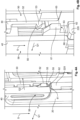
- a schematic, partially sectioned perspective view of a driving mechanism of the plug arrangement of
Figs. 1 to 3 in the latched state; - Fig. 4B
- a schematic, partially sectioned perspective view of the driving mechanism shown in
Fig. 4A in a detached state; - Fig. 5
- a schematic perspective view of a latching mechanism of the embodiment of
Figs. 1 to 3 ; and - Fig. 6
- a schematic, partially sectioned perspective view of a preferred configuration of a holding mechanism.
-
Figures 1 to 5 show a first embodiment of aplug arrangement 100. InFig. 6 , a special configuration of aholding mechanism 99 is shown, which can also be used in the first embodiment, for example. - The
plug arrangement 100 comprises in each case ahousing part 20 of aplug 120. Theplug 120 can, for example, be an electrical plug with which power or signals are transmitted. For this purpose, further elements may be present on theplug 120, in particular electrical contact elements (not shown). Theplug 120 shown can thus be connected to a cable and is then used to transmit the power or the signals to amating plug 200. Themating plug 200 shown is configured as a header that can be mounted on a product housing, for example. - In other configurations, other plugs are also possible, for example for the transmission of optical signals, for pneumatic or hydraulic connections or similar. It is also possible to use connectors that are not necessarily plugged in.
- The
plug 120 is configured to be plugged together with themating plug 200 along a plugging direction S. In a first step, theplug 120 is, for example, easily plugged together manually with themating plug 200. In order to then generate a large pressing force or mating force, theplug arrangement 100 has a pivotinglever 30, which can be attached to thehousing part 20. The pivotinglever 30 shown can only be moved rotationally relative to thehousing part 20, thus pivoted. In other configurations, an at least partial translational relative mobility can also be provided, at least in some positions of the pivotinglever 30 relative to thehousing part 20. - In order to move the plug 21 and the
mating plug 200 towards each other, theplug arrangement 100 has a pulling mechanism 250, which is configured here as a toothed mechanism 260.Teeth 261, which are formed on agear rack 262 on ahousing part 220 of themating plug 200 and on agearwheel segment 263 on the pivotinglever 30, engage with one another and convert the pivot movement of the pivotinglever 30 along a pivoting direction L into a translational relative movement. Due to the lever effect, the force required for this, which is applied to anactuation section 37 of the pivotinglever 30, can be relatively low. - In the example shown, the pivoting
lever 30 can be moved, in particular rotated, from aninitial position 31 to anend position 32. Pivoting beyond theinitial position 31 and theend position 32 can be prevented by the fact that the pivotinglever 30 abuts against stops. In other configurations, however, pivoting beyond theinitial position 31 and/or theend position 32 may also be possible. - However, pivoting the pivoting
lever 30 out of theinitial position 31 is only possible if a blockingelement 40 is in arelease position 42. If, on the other hand, the blockingelement 40 is in a blockingposition 41, the pivotinglever 30 is blocked from pivoting relative to thehousing part 20 by the blockingelement 40. In the embodiment shown, the blockingelement 40 is attached to the pivotinglever 30 and is guided so as to be displaceable relative thereto. The blockingposition 41 and therelease position 42 refer here to a relative position of the pivotinglever 30 to the blockingelement 40. The blocking effect of the blockingelement 40 is achieved here by a form-fit element 43 on the blockingelement 40 in the form of a projecting arm 44 engaging in arecess 48 on thehousing part 20. - In order to detach the blocking
effect 49 achieved by the blockingelement 40 and therecess 48, the blockingelement 40 is moved in the direction away from ashaft 23 on thehousing part 20 on which the pivotinglever 30 is mounted, thus in the example shown against the plugging direction S. This is achieved here by thehousing part 220 of themating plug 200 when it is plugged together with theplug 20. The blockingelement 40 is thus automatically transferred to therelease position 42 without any special additional action by a user or any apparatus on the blockingelement 40. - Since the blocking
element 40 simultaneously forms an extension element 35 for the pivotinglever 30, thelever length 39 is thereby extended and the force required for pivoting is further minimized. Furthermore, such a configuration has the advantage that in a transport state, as shown for example inFig. 1 , thelever length 39 is relatively short and thus the risk of damage is reduced. Thelever length 39 is defined here as the distance between theactuation section 37, which lies between twolever sections 38, and a central axis or axis of rotation of theshaft 23. At the same time, theplug arrangement 100 is already held in a configuration necessary for the plugging process by theblocking mechanism 49. In particular, the pivoting position of the pivotinglever 30 is fixed in theinitial position 31. - In order to secure the blocking
element 40 against unintentional displacement out of the blockingposition 41, a holding mechanism 99 (see, for example, the particularly preferred configuration inFig. 6 ) can be provided. In the example shown, the holdingmechanism 99 has a holdingelement 95 formed integrally with the rest of the blockingelement 40, which in particular has an outwardly projecting and elastically inwardlydeflectable projection 97, which can latch with a recess 96 and aprojection 97 on the rotating lever or pivotinglever 30. Due to the fact that asurface 98 on theprojection 97 does not run exactly perpendicularly to the direction of movement of the blockingelement 40 relative to the pivotinglever 30, but is slightly inclined to it, the blocking effect is automatically canceled by the holdingmechanism 99 if a force applied by themating plug 20 and acting on the blockingelement 40 exceeds a certain threshold. Theprojection 95 is then elastically deflected and disengages from theprojection 97. - If the pivoting
lever 30 is now pivoted from theinitial position 31 along a direction of rotation D to theend position 32, which is offset by 90 degrees, it lies flat on thehousing part 20. When theend position 32 is reached, the pivotinglever 30 is automatically fixed relative to thehousing part 20 by a securingmechanism 79. This is achieved by a securingelement 70 in the form of a latchingelement 71 on the blockingelement 40 latching with acorresponding element 75 on thehousing part 20. Both are configured as form-fit elements element 40 andhousing part 20 in the latched state. Due to the fact that the blockingelement 40 in this state is only displaceable along a transverse direction Q1 parallel to an upper side of thehousing 20 relative to the pivotinglever 30, the pivotinglever 30 is thereby indirectly fastened to thehousing part 20. - The securing
element 70 on the blockingelement 40 is configured as a projection 73, which projects inwards from anarm 72 towards thehousing 20. Theelement 75 on thehousing part 20 is configured as aledge 77, so that movement of the securingelement 70 and thus of the blockingelement 40 along the first transverse direction Q1 parallel to the upper side of thehousing 20 is possible. The blockingelement 40 can therefore be transferred back out of therelease position 42 into the blockingposition 41. - However, such a transfer is only possible if a stopping
mechanism 94 is deactivated by thehousing part 220 of themating plug 20. Activation is effected by aprojection 91 on thehousing part 220, which projects through thehousing part 20 of theplug 120 and elastically deflects a stoppingelement 90 on the blockingelement 40 only when theplug 120 is fully plugged together with the mating plug 200 (here specifically thehousing parts 20 and 220). The stoppingelement 90 here also comprises aprojection 92, which projects from an elasticallydeflectable arm 93. The stoppingelement 90 is again integral with the rest of the blockingelement 40. - As with the other mechanisms, an easy transfer back to a stopping position can be achieved by providing an inclined overrun slope on a side opposite a stopping side.
- Advantageously, the stopping
element 90 of the stoppingmechanism 94 can simultaneously function as the holdingelement 95 of theholding mechanism 99. This reduces the complexity and weight and enables simple manufacture. - In order to detach the latching caused by the securing
mechanism 79, a detachingelement 80 is provided on the blockingelement 40. This is configured as a pusher 81, in which pressing along a release direction L, which here runs perpendicularly to the upper side of thehousing part 20, is converted into a detaching movement on the securingsurface 70. The detachingelement 80 is connected integrally with the securingelement 70 and the rest of the blockingelement 40. A bearing that allows sufficient mobility is achieved by thin material bridges 82. - In the state shown in
Fig. 3 , the blockingelement 40 is already in the blockingposition 41. There, the detachingelement 80 is covered by the transparently shown pivotinglever 30. It is therefore not accessible to a user. Asignal part 87 is visible to the user through anopening 88 on the pivotinglever 30, so that the user (or a suitable apparatus) can recognize that a complete plugging with a securing device is present. - The disconnection of the
plug 120 from themating plug 200 takes place in the reverse order, i.e. fromFig. 3 to Fig. 2 and then toFig. 1 . The blockingelement 40 is moved relative to the pivotinglever 30 into therelease position 42. By actuating the detachingelement 80, the form fit between the lockingelement 40 and thehousing part 20 is canceled, whereby the pivotinglever 30 can be moved back from theend position 32 against the first transverse direction Q1 to theinitial position 31. - The
plug arrangement 100 shown here advantageously also comprises adriving mechanism 59, with which the blockingelement 40 is automatically transferred by themating plug 200 from therelease position 42 back to the blockingposition 41 when the pivotinglever 30 is in theinitial position 31 and the mating plug 202 is disconnected or unplugged from theplug 120. In the example shown, thedriving mechanism 59 is only active in theinitial position 31 of the pivotinglever 30. Outside theinitial position 31, in particular in theend position 32, thedriving mechanism 59 is deactivated. - The
driving mechanism 59 is again based on a form-fit principle. A drivingelement 50 on the blockingelement 40 engages in a form-fit manner in arecess 62 on thehousing part 220 of themating plug 200. An upper boundary of therecess 62 forms amating element 61 for the drivingelement 50. The drivingelement 50 as well as themating element 61 comprise anarm projection 53 of the drivingelement 50 serves as a form-fit element 54, which interacts with a form-fit element 65 on the housing 21 of themating plug 200. - The embodiment shown is configured such that the
driving mechanism 59 is automatically deactivated, i.e. in this case the form-fit elements 54, 65 are disengaged when the blockingposition 41 is reached. This is achieved by the fact that asurface 55 on the form-fit elements 54 does not extend completely perpendicularly to the direction of the relative movement between the blockingelement 40 andhousing part 220, which is restricted by corresponding guide elements. Rather, thesurface 55, which interacts with asurface 66 on themating element 61 in the latched state, is slightly inclined to a plane that runs perpendicularly to this direction. By appropriately dimensioning the width, thickness and length of thearm 52 and the inclination of thesurface 55, a defined force threshold can now be specified in view of the selected material, above which a force is converted by themating plug 200 into a sufficient deflection of the latchingprojection 53 and this is then pressed out of engagement with themating element 61. Before reaching the blockingposition 41, the force applied by themating plug 200 merely causes a displacement of the blockingelement 40 relative to the pivotinglever 30. A much lower force is required for this, as only the friction between the blockingelement 40 and the pivotinglever 30 needs to be overcome. Thedriving mechanism 59 automatically transfers the blockingelement 40 to the blockingposition 41 without any further action by a user, thereby fixing the pivotinglever 30 in theinitial position 31 required for connection to themating plug 30. - The holding
mechanism 99 shown inFig. 6 is based on the same principle of triggering from a certain force by an inclined surface, in this case thesurface 98 on theprojection 97. - In the example shown, the deflection of the latching
projection 53 takes place in a second transverse direction Q2, which runs perpendicularly to the plugging direction. In other embodiments, such a deflection may also occur along the first transverse direction Q1, which runs perpendicularly to the plugging direction S and perpendicularly to the second transverse direction Q2. According to the preferred configuration shown, elements of theblocking mechanism 49 also serve as elements of thedriving mechanism 59. For example, the arm 44 of theblocking mechanism 49 is also thearm 52 of the drivingelement 50. - The various solutions and mechanisms shown (49, 59, 79, 94, 99) can be independent of one another and each represent independent inventive solutions.
-
- 20
- housing part
- 23
- shaft
- 30
- pivoting lever
- 31
- initial position
- 32
- end position
- 35
- extension element
- 37
- actuation section
- 38
- lever section
- 39
- lever length
- 40
- blocking element
- 41
- blocking position
- 42
- release position
- 43
- form-fit element
- 44
- arm
- 48
- recess
- 49
- blocking mechanism
- 50
- driving element
- 51
- latching element
- 52
- arm
- 53
- latching projection
- 54
- form-fit element
- 55
- surface
- 59
- driving mechanism
- 61
- mating element
- 62
- recess
- 63
- arm
- 65
- form-fit element
- 66
- surface
- 70
- securing element
- 71
- latching element
- 72
- arm
- 73
- recess
- 74
- form-fit element
- 75
- element
- 76
- form-fit element
- 77
- ledge
- 79
- securing mechanism
- 80
- detaching element
- 81
- pusher
- 82
- material bridge
- 87
- signal part
- 88
- opening
- 90
- stopping element
- 91
- projection
- 92
- projection
- 93
- arm
- 94
- stopping mechanism
- 95
- holding element
- 96
- recess
- 99
- holding mechanism
- 100
- plug arrangement
- 120
- plug
- 200
- mating plug
- 220
- housing part
- 250
- pulling mechanism
- 260
- toothed mechanism
- 261
- teeth
- 262
- gear rack
- 263
- gearwheel segment
- D
- pivoting direction
- L
- release direction
- S
- plugging direction
- Q1
- first transverse direction
- Q2
- second transverse direction
Claims (15)
- Plug arrangement (100), comprising a housing part (20) for a plug (120) which can be plugged together with a mating plug (200) along a plugging direction (S), and a pivoting lever (30) which can be attached to the housing part (20) and, in the attached state, can be pivoted from an initial position (31) into an end position (32), wherein the arrangement (100) has a blocking element (40) which can be transferred from a blocking position (41) to a release position (42) and which, in the blocking position (41), blocks pivoting of the pivoting lever (30) out of the initial position (31) and, in the release position (42), releases pivoting of the pivoting lever (30), wherein the blocking element (40) has a driving element (50) which can be actuated by the mating plug (200) and with which the blocking element (40) is transferred by the mating plug (200) into the blocking position (41).
- Plug arrangement (100) according to claim 1, wherein the driving element (50) comprises form-fit elements (50) interacting with the mating plug (200).
- Plug arrangement (100) according to claim 1 or 2, wherein the driving element (50) is configured to interact with the mating plug (200) only in the initial position (31).
- Plug arrangement (100) according to one of claims 1 to 3, wherein the driving element (50) is configured to be deactivated when the blocking element (40) has reached the blocking position (41).
- Plug arrangement (100) according to one of claims 1 to 4, wherein the driving element (50) is configured to be deactivated when a defined tensile force between the plug (120) and the mating plug (200) is exceeded.
- Plug arrangement (100) according to one of claims 1 to 5, wherein the blocking element (40) is movably mounted on the pivoting lever (30).
- Plug arrangement (100) according to one of claims 1 to 6, wherein the blocking element (40) comprises a securing element (70) which is configured to automatically secure the blocking element (40) to the housing part (20) when the pivoting lever (30) reaches the end position (32).
- Plug arrangement (100) according to claim 7, wherein a detaching element (80), with which the securing element (70) is detached, is arranged to be inaccessible in the blocking position (41).
- Plug arrangement (100) according to one of claims 7 or 8, wherein the detaching element (80) is covered by the pivoting lever (30) in the blocking position (41).
- Plug arrangement (100) according to one of claims 1 to 9, wherein the blocking element (40) can be transferred into the blocking position (41) when the pivoting lever (30) is in the end position (32).
- Plug arrangement (100) according to one of claims 1 to 10, wherein at least in the release position (41) the blocking element (40) is an extension element (35) for the pivoting lever (30).
- Plug arrangement (100) according to one of claims 1 to 11, wherein the blocking element is pulled into the blocking position (41) by the mating plug (200).
- Plug arrangement (100) according to one of claims 1 to 12, wherein the blocking element (40) can be transferred into the release position (42) by the mating plug (200).
- Plug arrangement according to one of claims 1 to 13 and a housing part (21) of a mating plug (200).
- Plug arrangement (100) according to one of claims 1 to 3, comprising a pulling mechanism (52) which pulls the plug (120) towards the mating plug (200) when the pivoting lever (30) is transferred from the initial position (31) to the end position (32).
Applications Claiming Priority (1)
| Application Number | Priority Date | Filing Date | Title |
|---|---|---|---|
| DE102023105353.1A DE102023105353A1 (en) | 2023-03-03 | 2023-03-03 | Plug-in arrangement |
Publications (1)
| Publication Number | Publication Date |
|---|---|
| EP4425722A1 true EP4425722A1 (en) | 2024-09-04 |
Family
ID=90104635
Family Applications (1)
| Application Number | Title | Priority Date | Filing Date |
|---|---|---|---|
| EP24160258.0A Pending EP4425722A1 (en) | 2023-03-03 | 2024-02-28 | Plug arrangement |
Country Status (6)
| Country | Link |
|---|---|
| US (1) | US20240297460A1 (en) |
| EP (1) | EP4425722A1 (en) |
| JP (1) | JP7722643B2 (en) |
| KR (1) | KR102884532B1 (en) |
| CN (1) | CN118589229A (en) |
| DE (1) | DE102023105353A1 (en) |
Citations (2)
| Publication number | Priority date | Publication date | Assignee | Title |
|---|---|---|---|---|
| EP3249759A1 (en) * | 2016-05-24 | 2017-11-29 | Delphi International Operations Luxembourg S.à r.l. | Electrical connector with mate-assist lever and integrated cpa |
| US20220376435A1 (en) * | 2021-05-18 | 2022-11-24 | Te Connectivity Germany Gmbh | Plug Connector and Connector Set with a Lever Extension |
Family Cites Families (9)
| Publication number | Priority date | Publication date | Assignee | Title |
|---|---|---|---|---|
| JPH07220805A (en) * | 1994-02-01 | 1995-08-18 | Ryosei Denso Kk | Connector with lever |
| FR2962857B1 (en) * | 2010-07-16 | 2016-09-09 | Tyco Electronics France Sas | CONNECTOR WITH CPA DEVICE ON LOCKING ELEMENT |
| JP5979498B2 (en) * | 2013-10-29 | 2016-08-24 | 住友電装株式会社 | Lever type connector |
| FR3017003B1 (en) * | 2014-01-28 | 2017-10-27 | Delphi Int Operations Luxembourg Sarl | CONNECTION LEVER CONNECTION LEVER |
| JP6296352B2 (en) * | 2014-08-25 | 2018-03-20 | 住友電装株式会社 | Connector with lever |
| US9583860B1 (en) * | 2015-11-24 | 2017-02-28 | Te Connectivity Corporation | Electrical connector with recordable position assurance |
| DE102020132994A1 (en) * | 2020-12-10 | 2022-06-15 | Te Connectivity Germany Gmbh | Electrical plug-in device with a locking mechanism, which can be released by a counter-housing, for a position-securing element |
| KR102764083B1 (en) * | 2020-12-22 | 2025-02-05 | 현대자동차주식회사 | Connector assembly having device for dual position confirmation |
| DE102022118993A1 (en) * | 2022-07-28 | 2024-02-08 | Te Connectivity Germany Gmbh | Housing arrangement for an electrical plug with a plug-in aid as well as electrical plug and plug arrangement |
-
2023
- 2023-03-03 DE DE102023105353.1A patent/DE102023105353A1/en active Pending
-
2024
- 2024-02-28 EP EP24160258.0A patent/EP4425722A1/en active Pending
- 2024-02-28 JP JP2024028004A patent/JP7722643B2/en active Active
- 2024-02-28 KR KR1020240029046A patent/KR102884532B1/en active Active
- 2024-02-29 US US18/591,035 patent/US20240297460A1/en active Pending
- 2024-03-01 CN CN202410234475.0A patent/CN118589229A/en active Pending
Patent Citations (2)
| Publication number | Priority date | Publication date | Assignee | Title |
|---|---|---|---|---|
| EP3249759A1 (en) * | 2016-05-24 | 2017-11-29 | Delphi International Operations Luxembourg S.à r.l. | Electrical connector with mate-assist lever and integrated cpa |
| US20220376435A1 (en) * | 2021-05-18 | 2022-11-24 | Te Connectivity Germany Gmbh | Plug Connector and Connector Set with a Lever Extension |
Also Published As
| Publication number | Publication date |
|---|---|
| JP2024125188A (en) | 2024-09-13 |
| DE102023105353A1 (en) | 2024-09-05 |
| CN118589229A (en) | 2024-09-03 |
| KR102884532B1 (en) | 2025-11-10 |
| KR20240135379A (en) | 2024-09-10 |
| JP7722643B2 (en) | 2025-08-13 |
| US20240297460A1 (en) | 2024-09-05 |
Similar Documents
| Publication | Publication Date | Title |
|---|---|---|
| US7473124B1 (en) | Electrical plug assembly with bi-directional push-pull actuator | |
| US6851867B2 (en) | Cam-follower release mechanism for fiber optic modules with side delatching mechanisms | |
| CN108933355B (en) | Electrical connector with retractable structure | |
| MX2008012440A (en) | Electrical connector assembly with mate-assist and a wire dress cover. | |
| US9755407B2 (en) | Draw out apparatus for air circuit breaker | |
| CN216773623U (en) | Connector and communication cable connecting device | |
| CZ295785B6 (en) | Device for controlling discharge and release of power accumulating apparatus during pulling out of plug-in current switch | |
| CN102437478A (en) | Latch for a cable assembly | |
| CN107111073A (en) | Connector assembly | |
| CN107112170B (en) | Trigger-type control system for circuit breaker polar and release unit | |
| US20240297460A1 (en) | Plug Arrangement | |
| CN115377728A (en) | Plug connector and connector set with lever extension | |
| CN113439369A (en) | Plug connector housing and connection | |
| CN209232644U (en) | A kind of self-locking structure of rotary switch | |
| CN215291922U (en) | Lock and lock cylinder driving structure thereof | |
| CN114366227A (en) | Clip applier and method for driving drive shaft thereof | |
| EP2654134B1 (en) | Lever structures for electrical connectors | |
| CN110970275B (en) | Circuit breaker assemblies and electric operating devices | |
| US12567701B2 (en) | Connector | |
| EP2899817B1 (en) | Insertion frame for an electric switching device and insertion device | |
| CN109962370B (en) | electrical connector | |
| CN121663257B (en) | New energy automobile connector | |
| EP4358318A1 (en) | Electrical connector arrangement | |
| JP4632943B2 (en) | Open / close operation device | |
| CN219499056U (en) | Stabilizer lock structure |
Legal Events
| Date | Code | Title | Description |
|---|---|---|---|
| PUAI | Public reference made under article 153(3) epc to a published international application that has entered the european phase |
Free format text: ORIGINAL CODE: 0009012 |
|
| STAA | Information on the status of an ep patent application or granted ep patent |
Free format text: STATUS: THE APPLICATION HAS BEEN PUBLISHED |
|
| AK | Designated contracting states |
Kind code of ref document: A1 Designated state(s): AL AT BE BG CH CY CZ DE DK EE ES FI FR GB GR HR HU IE IS IT LI LT LU LV MC ME MK MT NL NO PL PT RO RS SE SI SK SM TR |
|
| STAA | Information on the status of an ep patent application or granted ep patent |
Free format text: STATUS: REQUEST FOR EXAMINATION WAS MADE |
|
| 17P | Request for examination filed |
Effective date: 20250221 |
|
| GRAP | Despatch of communication of intention to grant a patent |
Free format text: ORIGINAL CODE: EPIDOSNIGR1 |
|
| STAA | Information on the status of an ep patent application or granted ep patent |
Free format text: STATUS: GRANT OF PATENT IS INTENDED |
|
| RIC1 | Information provided on ipc code assigned before grant |
Ipc: H01R 13/629 20060101AFI20260625BHEP Ipc: H01R 13/639 20060101ALN20260625BHEP |
|
| RIC1 | Information provided on ipc code assigned before grant |
Ipc: H01R 13/629 20060101AFI20260701BHEP Ipc: H01R 13/639 20060101ALN20260701BHEP |
|
| INTG | Intention to grant announced |
Effective date: 20260708 |