EP4425693A1 - Battery module, and battery pack and vehicle including same - Google Patents
Battery module, and battery pack and vehicle including same Download PDFInfo
- Publication number
- EP4425693A1 EP4425693A1 EP23892763.6A EP23892763A EP4425693A1 EP 4425693 A1 EP4425693 A1 EP 4425693A1 EP 23892763 A EP23892763 A EP 23892763A EP 4425693 A1 EP4425693 A1 EP 4425693A1
- Authority
- EP
- European Patent Office
- Prior art keywords
- cell
- frame
- wall
- leakage prevention
- battery module
- Prior art date
- Legal status (The legal status is an assumption and is not a legal conclusion. Google has not performed a legal analysis and makes no representation as to the accuracy of the status listed.)
- Pending
Links
Images






Classifications
-
- H—ELECTRICITY
- H01—ELECTRIC ELEMENTS
- H01M—PROCESSES OR MEANS, e.g. BATTERIES, FOR THE DIRECT CONVERSION OF CHEMICAL ENERGY INTO ELECTRICAL ENERGY
- H01M50/00—Constructional details or processes of manufacture of the non-active parts of electrochemical cells other than fuel cells, e.g. hybrid cells
- H01M50/20—Mountings; Secondary casings or frames; Racks, modules or packs; Suspension devices; Shock absorbers; Transport or carrying devices; Holders
- H01M50/233—Mountings; Secondary casings or frames; Racks, modules or packs; Suspension devices; Shock absorbers; Transport or carrying devices; Holders characterised by physical properties of casings or racks, e.g. dimensions
-
- H—ELECTRICITY
- H01—ELECTRIC ELEMENTS
- H01M—PROCESSES OR MEANS, e.g. BATTERIES, FOR THE DIRECT CONVERSION OF CHEMICAL ENERGY INTO ELECTRICAL ENERGY
- H01M50/00—Constructional details or processes of manufacture of the non-active parts of electrochemical cells other than fuel cells, e.g. hybrid cells
- H01M50/20—Mountings; Secondary casings or frames; Racks, modules or packs; Suspension devices; Shock absorbers; Transport or carrying devices; Holders
- H01M50/204—Racks, modules or packs for multiple batteries or multiple cells
- H01M50/207—Racks, modules or packs for multiple batteries or multiple cells characterised by their shape
- H01M50/213—Racks, modules or packs for multiple batteries or multiple cells characterised by their shape adapted for cells having curved cross-section, e.g. round or elliptic
-
- H—ELECTRICITY
- H01—ELECTRIC ELEMENTS
- H01M—PROCESSES OR MEANS, e.g. BATTERIES, FOR THE DIRECT CONVERSION OF CHEMICAL ENERGY INTO ELECTRICAL ENERGY
- H01M50/00—Constructional details or processes of manufacture of the non-active parts of electrochemical cells other than fuel cells, e.g. hybrid cells
- H01M50/20—Mountings; Secondary casings or frames; Racks, modules or packs; Suspension devices; Shock absorbers; Transport or carrying devices; Holders
- H01M50/204—Racks, modules or packs for multiple batteries or multiple cells
-
- H—ELECTRICITY
- H01—ELECTRIC ELEMENTS
- H01M—PROCESSES OR MEANS, e.g. BATTERIES, FOR THE DIRECT CONVERSION OF CHEMICAL ENERGY INTO ELECTRICAL ENERGY
- H01M50/00—Constructional details or processes of manufacture of the non-active parts of electrochemical cells other than fuel cells, e.g. hybrid cells
- H01M50/20—Mountings; Secondary casings or frames; Racks, modules or packs; Suspension devices; Shock absorbers; Transport or carrying devices; Holders
- H01M50/204—Racks, modules or packs for multiple batteries or multiple cells
- H01M50/207—Racks, modules or packs for multiple batteries or multiple cells characterised by their shape
- H01M50/211—Racks, modules or packs for multiple batteries or multiple cells characterised by their shape adapted for pouch cells
-
- H—ELECTRICITY
- H01—ELECTRIC ELEMENTS
- H01M—PROCESSES OR MEANS, e.g. BATTERIES, FOR THE DIRECT CONVERSION OF CHEMICAL ENERGY INTO ELECTRICAL ENERGY
- H01M50/00—Constructional details or processes of manufacture of the non-active parts of electrochemical cells other than fuel cells, e.g. hybrid cells
- H01M50/20—Mountings; Secondary casings or frames; Racks, modules or packs; Suspension devices; Shock absorbers; Transport or carrying devices; Holders
- H01M50/249—Mountings; Secondary casings or frames; Racks, modules or packs; Suspension devices; Shock absorbers; Transport or carrying devices; Holders specially adapted for aircraft or vehicles, e.g. cars or trains
-
- H—ELECTRICITY
- H01—ELECTRIC ELEMENTS
- H01M—PROCESSES OR MEANS, e.g. BATTERIES, FOR THE DIRECT CONVERSION OF CHEMICAL ENERGY INTO ELECTRICAL ENERGY
- H01M50/00—Constructional details or processes of manufacture of the non-active parts of electrochemical cells other than fuel cells, e.g. hybrid cells
- H01M50/20—Mountings; Secondary casings or frames; Racks, modules or packs; Suspension devices; Shock absorbers; Transport or carrying devices; Holders
- H01M50/262—Mountings; Secondary casings or frames; Racks, modules or packs; Suspension devices; Shock absorbers; Transport or carrying devices; Holders with fastening means, e.g. locks
-
- H—ELECTRICITY
- H01—ELECTRIC ELEMENTS
- H01M—PROCESSES OR MEANS, e.g. BATTERIES, FOR THE DIRECT CONVERSION OF CHEMICAL ENERGY INTO ELECTRICAL ENERGY
- H01M50/00—Constructional details or processes of manufacture of the non-active parts of electrochemical cells other than fuel cells, e.g. hybrid cells
- H01M50/20—Mountings; Secondary casings or frames; Racks, modules or packs; Suspension devices; Shock absorbers; Transport or carrying devices; Holders
- H01M50/289—Mountings; Secondary casings or frames; Racks, modules or packs; Suspension devices; Shock absorbers; Transport or carrying devices; Holders characterised by spacing elements or positioning means within frames, racks or packs
- H01M50/291—Mountings; Secondary casings or frames; Racks, modules or packs; Suspension devices; Shock absorbers; Transport or carrying devices; Holders characterised by spacing elements or positioning means within frames, racks or packs characterised by their shape
-
- H—ELECTRICITY
- H01—ELECTRIC ELEMENTS
- H01M—PROCESSES OR MEANS, e.g. BATTERIES, FOR THE DIRECT CONVERSION OF CHEMICAL ENERGY INTO ELECTRICAL ENERGY
- H01M50/00—Constructional details or processes of manufacture of the non-active parts of electrochemical cells other than fuel cells, e.g. hybrid cells
- H01M50/20—Mountings; Secondary casings or frames; Racks, modules or packs; Suspension devices; Shock absorbers; Transport or carrying devices; Holders
- H01M50/289—Mountings; Secondary casings or frames; Racks, modules or packs; Suspension devices; Shock absorbers; Transport or carrying devices; Holders characterised by spacing elements or positioning means within frames, racks or packs
- H01M50/293—Mountings; Secondary casings or frames; Racks, modules or packs; Suspension devices; Shock absorbers; Transport or carrying devices; Holders characterised by spacing elements or positioning means within frames, racks or packs characterised by the material
-
- H—ELECTRICITY
- H01—ELECTRIC ELEMENTS
- H01M—PROCESSES OR MEANS, e.g. BATTERIES, FOR THE DIRECT CONVERSION OF CHEMICAL ENERGY INTO ELECTRICAL ENERGY
- H01M50/00—Constructional details or processes of manufacture of the non-active parts of electrochemical cells other than fuel cells, e.g. hybrid cells
- H01M50/60—Arrangements or processes for filling or topping-up with liquids; Arrangements or processes for draining liquids from casings
-
- H—ELECTRICITY
- H01—ELECTRIC ELEMENTS
- H01M—PROCESSES OR MEANS, e.g. BATTERIES, FOR THE DIRECT CONVERSION OF CHEMICAL ENERGY INTO ELECTRICAL ENERGY
- H01M50/00—Constructional details or processes of manufacture of the non-active parts of electrochemical cells other than fuel cells, e.g. hybrid cells
- H01M50/60—Arrangements or processes for filling or topping-up with liquids; Arrangements or processes for draining liquids from casings
- H01M50/609—Arrangements or processes for filling with liquid, e.g. electrolytes
-
- H—ELECTRICITY
- H01—ELECTRIC ELEMENTS
- H01M—PROCESSES OR MEANS, e.g. BATTERIES, FOR THE DIRECT CONVERSION OF CHEMICAL ENERGY INTO ELECTRICAL ENERGY
- H01M2220/00—Batteries for particular applications
- H01M2220/20—Batteries in motive systems, e.g. vehicle, ship, plane
-
- Y—GENERAL TAGGING OF NEW TECHNOLOGICAL DEVELOPMENTS; GENERAL TAGGING OF CROSS-SECTIONAL TECHNOLOGIES SPANNING OVER SEVERAL SECTIONS OF THE IPC; TECHNICAL SUBJECTS COVERED BY FORMER USPC CROSS-REFERENCE ART COLLECTIONS [XRACs] AND DIGESTS
- Y02—TECHNOLOGIES OR APPLICATIONS FOR MITIGATION OR ADAPTATION AGAINST CLIMATE CHANGE
- Y02E—REDUCTION OF GREENHOUSE GAS [GHG] EMISSIONS, RELATED TO ENERGY GENERATION, TRANSMISSION OR DISTRIBUTION
- Y02E60/00—Enabling technologies; Technologies with a potential or indirect contribution to GHG emissions mitigation
- Y02E60/10—Energy storage using batteries
Definitions
- the present disclosure relates to a battery module, and a battery pack and a vehicle including the same. Specifically, the present disclosure relates to a battery module capable of preventing leakage of a filler, and a battery pack and a vehicle including the same.
- Secondary batteries which are easy to apply depending on the product group and have electrical characteristics such as high energy density and the like, are generally used in electric vehicles (EVs) or hybrid electric vehicles (HEVs) that are driven by an electric drive source, as well as in portable devices. These secondary batteries are attracting attention as a new energy source for improving eco-friendliness and energy efficiency in that they have the primary advantage of being able to dramatically reduce the use of fossil fuels and in that no by-product is generated due to energy use.
- EVs electric vehicles
- HEVs hybrid electric vehicles
- Types of current secondary batteries widely used include lithium ion batteries, lithium polymer batteries, nickel cadmium batteries, nickel hydrogen batteries, nickel zinc batteries, and the like.
- the operating voltage of this unit secondary battery cell that is, the unit battery cell, is approximately 2.5V to 4.5V. Therefore, when an output voltage higher than this is required, a battery pack may be configured by connecting a plurality of battery cells in series. In addition, a battery pack may be configured by connecting multiple battery cells in parallel depending on the charge/discharge capacity required for the battery pack. Accordingly, the number of battery cells included in the battery pack may be set in various ways depending on the required output voltage or charge/discharge capacity.
- a common method is to preferentially configure a battery module including at least one battery cell and then add other components using the at least one battery module, thereby configuring a battery pack or battery rack.
- the conventional battery module is configured to include a plurality of battery cells and a cell frame.
- the conventional battery module is configured to further include a filler filled between the battery cells to prevent heat diffusion and secure cooling performance.
- the conventional battery module has a problem in which the filler leaks out of the cell frame.
- the filler may leak through the gap formed in the portion where the parts are coupled to each other.
- the present disclosure has been designed to solve the problems of the related art, and is directed to providing a battery module capable of preventing leakage of the filler, and a battery pack and a vehicle including the same.
- the present disclosure is also to provide a battery module capable of reducing manufacturing costs and increasing energy density, and a battery pack and a vehicle including the same.
- a battery module including: a plurality of battery cells; a cell frame configured to accommodate the plurality of battery cells; and a filler filled between the plurality of battery cells, wherein the at least a portion of the cell frame is recessed to form a leakage prevention groove for receiving the filler, wherein the cell frame includes: a frame wall forming a perimeter of the cell frame; and a cell accommodation portion provided inside the frame wall to accommodate the plurality of battery cells, and wherein the leakage prevention groove is provided between the frame wall and the cell accommodation portion.
- the leakage prevention groove may be provided along the frame wall.
- the cell accommodation portion may include: a plurality of cell accommodation holes arranged side by side such that the plurality of battery cells is respectively inserted into the same; and a cell accommodation wall formed along the outermost perimeter of the cell accommodation holes, and the leakage prevention groove may be provided between the cell accommodation wall and the frame wall.
- the cell accommodation wall may be configured to be inclined toward the leakage prevention groove.
- the leakage prevention groove may be provided in a shape surrounded by the cell accommodation portion and the frame wall.
- the leakage prevention groove may include: a plurality of first grooves formed between the adjacent cell accommodation holes among the plurality of cell accommodation holes; and second grooves formed between adjacent first grooves among the plurality of first grooves so as to communicate with the adjacent first grooves, and the first groove and the second groove may have different depths.
- the leakage prevention groove may include an inclined surface that is provided to be inclined toward the first groove between the first groove and the second groove, thereby guiding the flow of the filler.
- the height of the cell accommodation wall and the depth of the leakage prevention groove may be configured to correspond to the height of the frame wall.
- the cell frame may include: a cell top frame configured to accommodate the upper portions of the plurality of battery cells; and a cell bottom frame coupled to the bottom of the cell top frame and configured to accommodate the lower portions of the plurality of battery cells, and the leakage prevention groove may be provided in the cell bottom frame.
- the cell bottom frame may include a coupling portion to which the cell top frame is coupled, and the leakage prevention groove may be provided on the inner side of the coupling portion.
- the leakage prevention groove may be provided on the inner side of the second wall.
- the filler may be provided as a potting resin.
- a battery module including: a plurality of battery cells; a cell frame configured to accommodate the plurality of battery cells and having a top opening; and a filler filled into the cell frame through the top opening of the cell frame, wherein the cell frame has a leakage prevention groove configured to prevent the filler from leaking.
- the cell frame may include: a cell top frame configured to accommodate the upper portions of the plurality of battery cells; and a cell bottom frame coupled to the bottom of the cell top frame and configured to accommodate the lower portions of the plurality of battery cells, and the leakage prevention groove may be provided in the cell bottom frame.
- a battery pack including the battery module according to the present disclosure.
- a vehicle including the battery pack according to the processor disclosure.
- a cell frame including: a frame wall forming a rectangular frame; a cell accommodation portion provided inside the frame wall and configured to accommodate a plurality of battery cells; and a leakage prevention groove provided between the frame wall and the cell accommodation portion.
- the cell accommodation portion may include: a plurality of cylindrical cell accommodation holes arranged side by side such that the plurality of battery cells is respectively inserted into the same; and a cell accommodation wall formed along the outermost perimeter of the cell accommodation holes, and the leakage prevention groove may be provided between the cell accommodation wall and the frame wall.
- the leakage prevention groove may include: a plurality of first grooves formed between the adjacent cell accommodation holes among the plurality of cell accommodation holes; and second grooves formed between adjacent first grooves among the plurality of first grooves so as to communicate with the adjacent first grooves, and the first groove and the second groove may have different depths.
- a battery module capable of preventing leakage of a filler when injecting the filler, and a battery pack and a vehicle including the same.
- gasket or glue since the gasket or glue is not used, it is possible to reduce manufacturing costs, increase energy density, and prevent leakage of the filler.
- the present disclosure may have various other effects, and these will be described in the respective embodiments, or the description of effects that may be easily inferred by those skilled in the art will be omitted.
- FIG. 1 is an overall perspective view of a battery module according to an embodiment of the present disclosure
- FIG. 2 is an exploded perspective view of the battery module in FIG. 1 .
- a battery module 10 may include a plurality of battery cells 100, a cell frame 200 accommodating the plurality of battery cells 100, and a filler R filled between the plurality of battery cells 100.
- the battery cell 100 may be applied to any type of secondary battery, such as a prismatic, cylindrical, or pouch-type battery cell, and in this embodiment, the battery cell 100 is provided as a cylindrical battery cell.
- the plurality of battery cells 100 may be electrically connected to each other.
- the plurality of battery cells 100 may be arranged in columns and rows to form one battery module 10.
- the cell frame 200 may be provided to accommodate all of the plurality of battery cells 100. As shown in FIGS. 1 and 2 , the cell frame 200 may be provided in a box with a top opening and four walls. Some of the walls extend along the X-axis direction in the drawing, and the remaining of the walls extend along the Y-axis direction. The plurality of battery cells 100 is accommodated in the cell frame 200 while standing upright in the Z-axis direction. Specifically, referring to FIG. 2 , the cell frame 200 may include a frame wall 210 forming the perimeter of the cell frame 200 and a cell accommodation portion 220 that is provided inside the frame wall 210 and accommodates the plurality of battery cells 100.
- the cell frame 200 may be made into a single unit by filling the space between the plurality of battery cells 100 with the filler R. That is, the filler R may be filled into the space formed between the plurality of battery cells 100.
- the filler R may be filled into the space between the plurality of battery cells 100 in the height direction (Z-axis direction) of the battery module 10. Meanwhile, the hexahedral filler R indicated by a two-dot chain line in FIG. 2 is illustrated for convenience of understanding, and the entire space between the plurality of battery cells 100 may be filled with the filler R.
- the filler R may cover the upper and lower sides of the battery cell 100, thereby forming the structure of the battery module 10 together with the cell frame 200.
- the filler R may fix the plurality of battery cells 100 more stably and increase the heat dissipation efficiency of the plurality of battery cells 100, thereby improving the cooling performance of the battery cells 100.
- the filler R may prevent moisture or foreign substances from entering the battery cell 100, prevent chain ignition when a heat event occurs due to an abnormality in the battery cell 100, and improve the structural rigidity of the battery pack 20.
- the filler R may be a potting resin and may be provided to be mixed with beads such as glass bubbles.
- the potting resin may be formed by injecting a diluted resin material into the plurality of battery cells 100 and curing the same.
- the injection of the resin material may be performed at a room temperature of approximately 15 to 25 degrees C to prevent thermal damage to the plurality of battery cells 100.
- the filler R may be provided as a silicone resin. It is not limited to this, and the filler R may be provided as other resin materials capable of improving the fixation and heat dissipation efficiency of the battery cell 100 in addition to the silicone resin.
- the filler R may have a predetermined viscosity and may include at least two materials. Specifically, the filler R may be provided by mixing a predetermined resin and beads at a preset ratio. It is possible to reduce the cost of the potting resin for the filler R through mixing of the beads and adjust physical properties such as viscosity of the filler R depending on the mixing ratio.
- the filler R may guide the thermal balance of the battery cell 100 and prevent cooling differences in the battery cell 100, thereby preventing local deterioration of the battery cell 100.
- the safety of the battery cell 100 may be significantly improved by preventing local deterioration of the battery cell 100.
- the filler R may serve as an insulator that prevents current from flowing to the adjacent battery cells 100 when damage, etc. occurs due to an abnormal situation in at least one specific battery cell 100 among the plurality of battery cells 100.
- the filler R may further include a material having high specific-heat performance. Accordingly, the filler R may increase the thermal mass and delay a temperature increase of the battery cell 100 even in situations such as rapid charging and discharging of the battery cell 100, thereby preventing a rapid temperature rise.
- the filler R may further include a material having high heat resistance performance. Accordingly, the filler R may effectively prevent thermal runaway to adjacent battery cells when a thermal event such as overheating occurs in at least one specific battery cell 100 among the plurality of battery cells 100.
- the filler R may further include a material having high flame-retardant performance. Accordingly, the filler R may minimize the risk of fire occurring when a thermal event such as overheating occurs in at least one specific battery cell 100 among the plurality of battery cells 100.
- the filler when the filler is injected into the cell frame, the filler may overflow and leak out of the cell frame.
- the present disclosure provides a battery module 10 including a leakage prevention groove 230 in which at least a portion of the cell frame 200 is recessed to accommodate the filler R in order to prevent leakage of the filler R. Accordingly, the filler R may be accommodated in the leakage prevention groove 230 before leaking out of the cell frame 200, thereby preventing the filler R from leaking out of the cell frame 200.
- FIG. 3 is a perspective view of the cell frame in FIG. 1
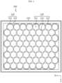
- FIG. 4 is a diagram of the cell frame in FIG. 1 viewed from above
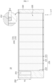
- FIG. 5 is a diagram of the battery module corresponding to the cross-section I-I' in FIG. 3 .
- the cell frame 200 of the present disclosure may accommodate the plurality of battery cells 100 and have a top opening, so that the cell frame 200 may be filled with a filler R through the top opening of the cell frame 200.
- the leakage prevention groove 230 it would be desirable for the leakage prevention groove 230 to be provided on the top of the cell frame 200 to prevent the filler R from leaking.
- the present disclosure provides the cell frame 200 including a frame wall 210 forming a rectangular frame, a cell accommodation portion 220 provided on the inner side of the frame wall 210 to accommodate a plurality of battery cells 100, and a leakage prevention groove 230 provided between the frame wall 210 and the cell accommodation portions 220.
- the cell frame 200 may be manufactured integrally by injection molding using plastic.
- the cell accommodation portion 220 may include a plurality of cell accommodation holes 221 arranged side by side such that the plurality of battery cells 100 is respectively inserted thereinto and a cell accommodation wall 222 formed along the outermost perimeter of the cell accommodation holes 221.
- the cell accommodation portion 220 may include a cell support portion 223 that forms the plurality of cell accommodation holes 221 and supports the outer side of the battery cell 100.
- the cell support portion 223 may support the lower portion of the peripheral surface of the battery cell 100.
- the leakage prevention groove 230 may be provided between the frame wall 210 and the cell accommodation portion 220.
- the leakage prevention groove 230 may be provided between the cell accommodation wall 222 and the frame wall 210.
- the leakage prevention groove 230 may be provided along the frame wall 210. Accordingly, when the filler R filled into the cell accommodation portion 220 leaks to the outside of the cell accommodation wall 222, the filler R may be primarily accommodated in the leakage prevention groove 230 and prevented from overflowing the frame wall 210.
- the cell accommodation wall 222 may be configured to be inclined such that its height gradually decreases toward the leakage prevention groove 230. As a result, the cell accommodation wall 222 may guide the filler R leaking from the cell accommodation portion 220 to be accommodated in the leakage prevention groove 230, thereby effectively preventing the leakage of the filler R.
- the plurality of cell accommodation holes 221 may be provided in a cylindrical shape. Accordingly, as shown in FIG. 4 , when the cell frame 200 is viewed from above, the plurality of cell accommodation holes 221 may be provided in a circular shape.
- the leakage prevention groove 230 may be provided along the frame wall 210 and may be provided between the two cell accommodation holes 221 provided adjacent to the frame wall 210. That is, the leakage prevention groove 230 may be provided between two adjacent cell accommodation holes 221 among the plurality of cell accommodation holes 221 and the frame wall 210. In this case, as shown in FIG. 4 , the leakage prevention groove 230 may be provided in a shape surrounded by the cell accommodation portion 220 and the frame wall 210.
- the plurality of leakage prevention grooves 230 may be provided to be spaced apart from each other, or as shown in FIGS. 3 to 5 , the plurality of the leakage prevention grooves 230 may be provided connected to each other.
- the leakage prevention groove 230 may include a plurality of first grooves 231 formed between adjacent cell accommodation holes 221 among the plurality of cell accommodation holes 221 and second grooves 232 formed between adjacent first grooves 231 among the plurality of first grooves 231 so as to communicate with the adjacent first grooves 231. That is, a plurality of first grooves 231 and a plurality of second grooves 232 may be provided to be spaced apart from each other, respectively, and the first groove 231 and the second groove 232 may be provided to be connected to each other.
- the battery cell 100 is provided as a cylindrical cell
- the shape of the first groove 231 is formed in the empty space between the plurality of cell accommodation holes 221, it may be easy to manufacture the first grooves 231 and the second grooves 232 when manufacturing a plastic injection molded product of the cell frame 200.
- the leakage prevention grooves 230 are provided in all spaces formed between the frame wall 210 and the cell accommodation portion 220, even if the filler R leaks in any direction, the leakage prevention groove 230 may accommodate the filler R. Meanwhile, although the filler R is injected from the top into the cell accommodation wall 222 in order to reduce material costs, the filler R may overflow the cell accommodation wall 222 due to a delay of the injection end time or other reasons such as vibration. At this time, the filler R flows into the first grooves 231 and the second grooves 232, instead of flowing out of the cell frame 200. Although FIG. 5 shows an example in which the first groove 231 is filled with the overflowing filler R, the first groove 231 may not be fully filled with the filler R.
- the depth h1 of the first groove 231 and the depth h2 of the second groove 232 may be configured to be different from each other.
- the first groove 231 may be formed deeper than the second groove 232 and may serve to store the leaking filler R. That is, the depth h1 of the first groove 231 may be formed greater than the depth h2 of the second groove 232.
- the leakage prevention groove 230 may include an inclined surface 233 that is provided such that its height gradually decreases toward the first groove 231 between the first groove 231 and the second groove 232, thereby guiding the flow of the filler R.
- the filler R may once flow into the second groove 232, which has a lower depth, and then flow further along the inclined surface 233 to be guided to the first groove 231, which has a greater depth, and stored therein, thereby more effectively preventing the filler R from leaking out of the cell frame 200.
- FIG. 6 is an overall perspective view of a battery module according to another embodiment of the present disclosure
- FIG. 7 is an exploded perspective view of the battery module in FIG. 6 .
- the cell frame 200 may include a cell top frame 202 that accommodates the upper portions of the plurality of battery cells 100 and a cell bottom frame 201 that is coupled to the bottom of the cell top frame 202 and accommodates the lower portions of the plurality of battery cells 100.
- the portion where the cell top frame 202 and the cell bottom frame 201 are coupled may have a certain difference therebetween according to the difference in height between the plurality of battery cells 100 and the cell frame 200. Therefore, if there is no structure such as the leakage prevention groove 230, the filler R may leak to the outside of the cell frame 200 through the coupled portion.
- the leakage prevention groove 230 is provided to prevent the filler R from leaking through the portion where the cell top frame 202 and the cell bottom frame 201 are coupled when the cell top frame 202 and the cell bottom frame 201 are coupled.
- the leakage prevention groove 230 may be provided in the cell bottom frame 201.
- the leakage prevention groove 230 is integrally provided with the cell frame 200, the filler R may be accommodated in the leakage prevention groove 230 before leaking to the outside of the cell frame 200 without adding any other members, so when the cell frame 200 is provided separately into the cell top frame 202 and the cell bottom frame 201, it is possible to prevent the filler R from leaking to the outside of the cell frame 200 through the coupling portion thereof.
- manufacturing costs may be reduced and energy density may be increased.
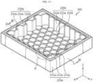
- FIG. 8 is a perspective view of an embodiment of the cell bottom frame in FIG. 6
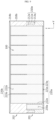
- FIG. 9 is a diagram of the battery module corresponding to the cross-section II-II' in FIG. 8 .
- the cell bottom frame 201 and the cell top frame 202 may include frame walls 210a and 210b and cell accommodation portions 220a and 220b, respectively.
- the frame wall 210a of the cell bottom frame 201 forms the perimeter of the cell bottom frame 201
- the cell accommodation portion 220a has the same structure as the cell accommodation portion 220 of the cell frame 200 described with reference to FIGS. 3 to 5 .
- the frame wall 210b of the cell top frame 202 may form the perimeter of the cell top frame 202, and may further include a leakage prevention wall 214b in which a portion protrudes upward such that the filler R is prevented from leaking when the cell frame 200 is filled with the filler R.
- the cell accommodation portion 220b of the cell top frame 202 has a structure that is the same as the cell accommodation portion 220 of the cell frame 200 described with reference to FIGS. 3 to 5 but is flipped up and down.
- the cell support portion 223b of the cell top frame 202 may support the upper portion of the peripheral surface of the battery cell 100.
- the cell top frame 202 may be coupled so as to accommodate the entire cell bottom frame 201.
- the cell bottom frame 201 may include a coupling portion 213a to which the cell top frame 202 is coupled.
- the coupling portion 213a may be provided by recessing a portion of the frame wall 210a. That is, a portion of the cell top frame 202 may be inserted into and coupled to the coupling portion 213a of the cell bottom frame 201.
- the cell bottom frame 201 and the cell top frame 202 may be firmly coupled to each other without any special members such as gaskets or glue, thereby improving the rigidity of the battery module 10.
- the leakage prevention groove 230a may be provided between the frame wall 210a and the cell accommodation portion 220a.
- the leakage prevention groove 230a may be provided between the cell accommodation wall 222a and the frame wall 210a.
- the leakage prevention groove 230a may be provided along the frame wall 210a. Accordingly, when the filler R filled into the cell accommodation portion 220a leaks to the outside of the cell accommodation wall 222a, it may be primarily accommodated in the leakage prevention groove 230a and then prevented from overflowing the frame wall 210a.
- the cell accommodation wall 222a may be configured to be inclined such that its height gradually decreases toward the leakage prevention groove 230a. As a result, the cell accommodation wall 222a may guide the filler R leaking from the cell accommodation portion 220a to be accommodated in the leakage prevention groove 230a, thereby more effectively preventing the leakage of the filler R.
- the cell bottom frame 201 may include a first wall 211a defined as the outer wall of the cell bottom frame 201 and a second wall 212a provided to be spaced inward from the first wall 211a, and the coupling portion 213a may be provided between the first wall 211a and the second wall 212a so that a portion of the frame wall 210b of the cell top frame 202 may be inserted into the same.
- the leakage prevention groove 230a may be provided on the inner side of the coupling portion 213a and may be provided on the inner side of the second wall 212a.
- the filler R may be primarily accommodated inside the coupling portion 213a to prevent leakage, and the coupling portion 213a may also play the same role as the leakage prevention groove 230a, thereby secondarily preventing the leakage of the filler R.
- the plurality of cell accommodation holes 221a may be provided in a cylindrical shape.
- the leakage prevention groove 230a may be provided along the frame wall 210a and may be provided between two cell accommodation holes 221a adjacent to the frame wall 210a. That is, the leakage prevention groove 230a may be provided between two adjacent cell accommodation holes 221a among the plurality of cell accommodation holes 221a and the frame wall 210a. In this case, as shown in FIG. 8 , the leakage prevention groove 230a may be provided in a shape surrounded by the cell accommodation portion 220a and the frame wall 210a.
- a plurality of leakage prevention grooves 230a may be provided to be spaced apart from each other.
- the leakage prevention groove 230a of the cell bottom frame 201 may be configured as only a plurality of first grooves 231a formed between adjacent cell accommodation holes 221a among the plurality of cell accommodation holes 221a.
- the first groove 231a may serve to store the leaking filler R, as well as accommodating the same.
- FIG. 10 is a perspective view of another embodiment of the cell bottom frame in FIG. 6
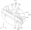
- FIG. 11 is an enlarged view of portion A in FIG. 10
- FIG. 12 is a diagram of the battery module corresponding to the cross-section III-III' in FIG. 11 .
- the filler R is likely to leak into the empty space between the plurality of first grooves 231a. Accordingly, as shown in FIGS. 10 to 12 , a plurality of the leakage prevention grooves 230a may be provided to be connected to each other. Accordingly, since the leakage prevention groove 230a is provided in all spaces formed between the frame wall 210a and the cell accommodation portion 220a, even if the filler R leaks in any direction, the filler R may be accommodated.
- the leakage prevention groove 230a may include a plurality of first grooves 231a formed between adjacent cell accommodation holes 221a among the plurality of cell accommodation holes 221a and second grooves 232a formed between adjacent first grooves 231a among the plurality of first grooves 231a so as to communicate with the adjacent first grooves 231a. That is, a plurality of first grooves 231a and a plurality of second grooves 232a may be provided to be spaced apart from each other, respectively, and the first groove 231a and the second groove 232a may be provided to be connected to each other.
- the depth h3 of the first groove 231a and the depth h4 of the second groove 232a may be configured to be different from each other.
- the first groove 231a may be formed deeper than the second groove 232a and may serve to store the leaking filler R. That is, the depth h3 of the first groove 231a may be formed greater than the depth h4 of the second groove 232a.
- the leakage prevention groove 230a may include an inclined surface 233a that is provided such that its height gradually decreases toward the first groove 231a between the first groove 231a and the second groove 232a, thereby guiding the flow of the filler R.
- the filler R may once flow into the second groove 232a, which has a lower depth, and then flow further along the inclined surface 233a to be guided to the first groove 231a, which has a greater depth, and stored therein, thereby more effectively preventing the filler R from leaking out of the cell bottom frame 201 without deteriorating the rigidity of the cell bottom frame 201.
- FIG. 13 is a perspective view of another embodiment of the cell bottom frame in FIG. 6
- FIG. 14 is a diagram of the battery module corresponding to the cross-section IV-IV' in FIG. 13 .
- the first groove 231a and the second groove 232a may be provided to be connected to each other, and the depth h5 of the first groove 231a and the depth h6 of the second groove 232a may be formed to be the same.
- the height of the cell accommodation wall 222a and the depth of the leakage prevention groove 230a may be provided to correspond to the height of the frame wall 210a.
- the cell accommodation wall 222a and the frame wall 210a may be provided to be completely spaced apart from each other.
- the leakage prevention grooves 230a may be defined as all spaces between the cell accommodation wall 222a and the frame wall 210a. Accordingly, if the filler R leaks to the outside of the cell accommodation wall 222a, the leakage prevention groove 230a may store a large amount of filler R, thereby preventing the filler R from leaking to the outside of the cell frame 210a.
- FIG. 15 is a perspective view of a battery pack including the battery module in FIG. 6 .
- the battery pack 20 may include a pack case 21 that accommodates the battery module 10.
- the pack case 21 may have an accommodation room provided therein to accommodate the battery module 10.
- the accommodation room may be a bottom space of the pack case 21 that is stepped from the edge of the pack case 21 to a predetermined depth.
- the pack case 21 may also be configured to further include a pack cover that covers the battery module 10.
- the pack case 21 may be bolted to the pack cover through a bolting member.
- the battery pack 20 may include a battery management system (BMS) as a control module for controlling the battery module 10.
- BMS battery management system
- the control module may manage the battery module 10 through charging and discharging, voltage, temperature sensing, etc. of the battery module 10.
- the battery pack 20 may further include a cooling unit such as a heat sink for cooling the battery module 10.
- the heat sink may be air-cooled or water-cooled, and may be provided above or below the bottom of the pack case 21.
- it may further include various other components, such as components of the battery pack 20 known at the time of filing the present disclosure, such as relays, current sensors, and the like.
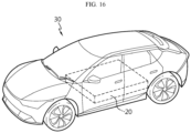
- FIG. 16 is a perspective view of a vehicle including the battery pack in FIG. 15 .
- the present disclosure may provide a vehicle 30 including at least one battery pack 20 described above. That is, the battery pack 20 according to the present disclosure may be applied to vehicles such as electric vehicles or hybrid vehicles.
- the battery pack 20 may be installed in the car body frame under the vehicle seat or trunk space.
- a battery module 10 capable of reducing costs and increasing energy density while preventing leakage of the filler, and a battery pack 20 and a vehicle 30 including the same.
- the battery pack 20 according to the present disclosure may also be applied to ESSs (Energy Storage Systems) or various electric devices in addition to vehicles.
- ESSs Electronicgy Storage Systems
- devices, instruments, and equipment including the battery pack 20, such as the vehicle 30 according to the embodiment of the present disclosure may include the battery module 10 described above, so they may be implemented to have all the advantages of the battery module 10.
Landscapes
- Chemical & Material Sciences (AREA)
- Chemical Kinetics & Catalysis (AREA)
- Electrochemistry (AREA)
- General Chemical & Material Sciences (AREA)
- Engineering & Computer Science (AREA)
- Aviation & Aerospace Engineering (AREA)
- Battery Mounting, Suspending (AREA)
- Secondary Cells (AREA)
Abstract
Description
- The present disclosure relates to a battery module, and a battery pack and a vehicle including the same. Specifically, the present disclosure relates to a battery module capable of preventing leakage of a filler, and a battery pack and a vehicle including the same.
- The present application claims priority to
Korean Patent Application No. 10-2022-0181620 filed on December 22, 2022 - In addition, the present application claims priority to
Korean Patent Application No. 10-2023-0073840 filed on June 08, 2023 - Secondary batteries, which are easy to apply depending on the product group and have electrical characteristics such as high energy density and the like, are generally used in electric vehicles (EVs) or hybrid electric vehicles (HEVs) that are driven by an electric drive source, as well as in portable devices. These secondary batteries are attracting attention as a new energy source for improving eco-friendliness and energy efficiency in that they have the primary advantage of being able to dramatically reduce the use of fossil fuels and in that no by-product is generated due to energy use.
- Types of current secondary batteries widely used include lithium ion batteries, lithium polymer batteries, nickel cadmium batteries, nickel hydrogen batteries, nickel zinc batteries, and the like. The operating voltage of this unit secondary battery cell, that is, the unit battery cell, is approximately 2.5V to 4.5V. Therefore, when an output voltage higher than this is required, a battery pack may be configured by connecting a plurality of battery cells in series. In addition, a battery pack may be configured by connecting multiple battery cells in parallel depending on the charge/discharge capacity required for the battery pack. Accordingly, the number of battery cells included in the battery pack may be set in various ways depending on the required output voltage or charge/discharge capacity.
- Meanwhile, in the case of configuring a battery pack by connecting a plurality of battery cells in series/parallel, a common method is to preferentially configure a battery module including at least one battery cell and then add other components using the at least one battery module, thereby configuring a battery pack or battery rack.
- The conventional battery module is configured to include a plurality of battery cells and a cell frame. Here, the conventional battery module is configured to further include a filler filled between the battery cells to prevent heat diffusion and secure cooling performance.
- However, the conventional battery module has a problem in which the filler leaks out of the cell frame. In particular, in the case of a structure in which the cell frame is configured by coupling separate upper and lower parts, there is a problem in which the filler may leak through the gap formed in the portion where the parts are coupled to each other.
- To solve this problem, in the conventional battery module, there was an attempt to fill the gap between the upper and lower parts of the cell frame with gaskets or glue, thereby preventing the filler from leaking out of the cell frame. However, in the conventional battery module, the addition of separate gaskets or glue increases the manufacturing cost and the size of the entire battery module, which is disadvantageous to energy density.
- Therefore, there is a need to provide a battery module capable of reducing manufacturing costs and increasing energy density while preventing leakage of the fillers, and a battery pack and a vehicle including the same.
- Accordingly, the present disclosure has been designed to solve the problems of the related art, and is directed to providing a battery module capable of preventing leakage of the filler, and a battery pack and a vehicle including the same.
- In addition, the present disclosure is also to provide a battery module capable of reducing manufacturing costs and increasing energy density, and a battery pack and a vehicle including the same.
- The technical problems to be solved by the present disclosure are not limited to the technical problems described above, and other technical problems not mentioned above will be clearly understood by those skilled in the art from the following description of the present disclosure.
- In one aspect of the present disclosure, there is provided a battery module including: a plurality of battery cells; a cell frame configured to accommodate the plurality of battery cells; and a filler filled between the plurality of battery cells, wherein the at least a portion of the cell frame is recessed to form a leakage prevention groove for receiving the filler, wherein the cell frame includes: a frame wall forming a perimeter of the cell frame; and a cell accommodation portion provided inside the frame wall to accommodate the plurality of battery cells, and wherein the leakage prevention groove is provided between the frame wall and the cell accommodation portion.
- The leakage prevention groove may be provided along the frame wall.
- The cell accommodation portion may include: a plurality of cell accommodation holes arranged side by side such that the plurality of battery cells is respectively inserted into the same; and a cell accommodation wall formed along the outermost perimeter of the cell accommodation holes, and the leakage prevention groove may be provided between the cell accommodation wall and the frame wall.
- The cell accommodation wall may be configured to be inclined toward the leakage prevention groove.
- The plurality of cell accommodation holes may be provided in a cylindrical shape, and the leakage prevention groove may be provided between adjacent cell accommodation holes among the plurality of cell accommodation holes and the frame wall.
- The leakage prevention groove may be provided in a shape surrounded by the cell accommodation portion and the frame wall.
- A plurality of leakage prevention groove may be provided to be spaced apart from each other, and the plurality of the leakage prevention grooves may be provided to be connected to each other.
- The leakage prevention groove may include: a plurality of first grooves formed between the adjacent cell accommodation holes among the plurality of cell accommodation holes; and second grooves formed between adjacent first grooves among the plurality of first grooves so as to communicate with the adjacent first grooves, and the first groove and the second groove may have different depths.
- The leakage prevention groove may include an inclined surface that is provided to be inclined toward the first groove between the first groove and the second groove, thereby guiding the flow of the filler.
- The height of the cell accommodation wall and the depth of the leakage prevention groove may be configured to correspond to the height of the frame wall.
- The cell frame may include: a cell top frame configured to accommodate the upper portions of the plurality of battery cells; and a cell bottom frame coupled to the bottom of the cell top frame and configured to accommodate the lower portions of the plurality of battery cells, and the leakage prevention groove may be provided in the cell bottom frame.
- The cell bottom frame may include a coupling portion to which the cell top frame is coupled, and the leakage prevention groove may be provided on the inner side of the coupling portion.
- The cell bottom frame may include: a first wall defined as the outer wall of the cell bottom frame; and a second wall spaced inward from the first wall, and the coupling portion may be provided between the first wall and the second wall such that a portion of the cell top frame is inserted into the same.
- The leakage prevention groove may be provided on the inner side of the second wall.
- The filler may be provided as a potting resin.
- According to another aspect of the present disclosure, there is provided a battery module including: a plurality of battery cells; a cell frame configured to accommodate the plurality of battery cells and having a top opening; and a filler filled into the cell frame through the top opening of the cell frame, wherein the cell frame has a leakage prevention groove configured to prevent the filler from leaking.
- Here, the cell frame may include: a cell top frame configured to accommodate the upper portions of the plurality of battery cells; and a cell bottom frame coupled to the bottom of the cell top frame and configured to accommodate the lower portions of the plurality of battery cells, and the leakage prevention groove may be provided in the cell bottom frame.
- In addition, according to another aspect of the present disclosure, there is provided a battery pack including the battery module according to the present disclosure.
- In addition, according to another aspect of the present disclosure, there is provided a vehicle including the battery pack according to the processor disclosure.
- In addition, according to another aspect of the present disclosure, there is provided a cell frame including: a frame wall forming a rectangular frame; a cell accommodation portion provided inside the frame wall and configured to accommodate a plurality of battery cells; and a leakage prevention groove provided between the frame wall and the cell accommodation portion.
- The cell accommodation portion may include: a plurality of cylindrical cell accommodation holes arranged side by side such that the plurality of battery cells is respectively inserted into the same; and a cell accommodation wall formed along the outermost perimeter of the cell accommodation holes, and the leakage prevention groove may be provided between the cell accommodation wall and the frame wall.
- The leakage prevention groove may include: a plurality of first grooves formed between the adjacent cell accommodation holes among the plurality of cell accommodation holes; and second grooves formed between adjacent first grooves among the plurality of first grooves so as to communicate with the adjacent first grooves, and the first groove and the second groove may have different depths.
- According to the present disclosure, it is possible to provide a battery module capable of preventing leakage of a filler when injecting the filler, and a battery pack and a vehicle including the same.
- Additionally, it is possible to prevent the filler, in the case where cell frames accommodating the upper and lower portions of the battery cell are coupled to each other, from leaking through the gap between the coupled cell frames.
- In addition, since the gasket or glue is not used, it is possible to reduce manufacturing costs, increase energy density, and prevent leakage of the filler.
- Furthermore, the present disclosure may have various other effects, and these will be described in the respective embodiments, or the description of effects that may be easily inferred by those skilled in the art will be omitted.
- The accompanying drawings illustrate a preferred embodiment of the present disclosure and, together with the detailed description of the disclosure, serve to provide further understanding of the technical features of the present disclosure, and thus, the present disclosure is not construed as being limited to the drawing.
-
FIG. 1 is an overall perspective view of a battery module according to an embodiment of the present disclosure. -
FIG. 2 is an exploded perspective view of the battery module inFIG. 1 . -
FIG. 3 is a perspective view of the cell frame inFIG. 1 . -
FIG. 4 is a diagram of the cell frame inFIG. 1 viewed from above. -
FIG. 5 is a diagram of the battery module corresponding to the cross-section I-I' inFIG. 3 . -
FIG. 6 is an overall perspective view of a battery module according to another embodiment of the present disclosure. -
FIG. 7 is an exploded perspective view of the battery module inFIG. 6 . -
FIG. 8 is a perspective view of an embodiment of the cell bottom frame inFIG. 6 . -
FIG. 9 is a diagram of the battery module corresponding to the cross-section II-II' inFIG. 8 . -
FIG. 10 is a perspective view of another embodiment of the cell bottom frame inFIG. 6 . -
FIG. 11 is an enlarged view of portion A inFIG. 10 . -
FIG. 12 is a diagram of the battery module corresponding to the cross-section III-III' inFIG. 11 . -
FIG. 13 is a perspective view of another embodiment of the cell bottom frame inFIG. 6 . -
FIG. 14 is a diagram of the battery module corresponding to the cross-section IV-IV' inFIG. 13 . -
FIG. 15 is a perspective view of a battery pack including the battery module inFIG. 6 . -
FIG. 16 is a perspective view of a vehicle including the battery pack inFIG. 15 . - Hereinafter, preferred embodiments of the present disclosure will be described in detail with reference to the accompanying drawings. Prior to the description, it should be understood that the terms used in the specification and the appended claims should not be construed as limited to general and dictionary meanings, but interpreted based on the meanings and concepts corresponding to technical aspects of the present disclosure on the basis of the principle that the inventor is allowed to define terms appropriately for the best explanation.
- Therefore, since the embodiments described in this specification and the configurations shown in the drawings are only one of the most preferred embodiments of the present disclosure and do not represent the entire technical idea of the present disclosure, it should be understood that there may be various equivalents thereto and modifications at the time of filing the present application.
- In the drawings, the sizes of respective components or specific parts constituting the components are exaggerated, omitted, or schematically illustrated for convenience and clarity of explanation. Therefore, the sizes of the respective components do not entirely reflect the actual sizes. Descriptions of related known functions or detailed descriptions of configurations, which may obscure the subject matter of the present disclosure, may be omitted. For reference, in this specification, terms indicating direction are based on the components shown in the attached drawings, and are relative terms that may vary depending on the posture or position of the actual components.
-
FIG. 1 is an overall perspective view of a battery module according to an embodiment of the present disclosure, andFIG. 2 is an exploded perspective view of the battery module inFIG. 1 . - Referring to
FIGS. 1 and2 , abattery module 10 according to an embodiment of the present disclosure may include a plurality ofbattery cells 100, acell frame 200 accommodating the plurality ofbattery cells 100, and a filler R filled between the plurality ofbattery cells 100. - The
battery cell 100 may be applied to any type of secondary battery, such as a prismatic, cylindrical, or pouch-type battery cell, and in this embodiment, thebattery cell 100 is provided as a cylindrical battery cell. The plurality ofbattery cells 100 may be electrically connected to each other. The plurality ofbattery cells 100 may be arranged in columns and rows to form onebattery module 10. - Meanwhile, the
cell frame 200 may be provided to accommodate all of the plurality ofbattery cells 100. As shown inFIGS. 1 and2 , thecell frame 200 may be provided in a box with a top opening and four walls. Some of the walls extend along the X-axis direction in the drawing, and the remaining of the walls extend along the Y-axis direction. The plurality ofbattery cells 100 is accommodated in thecell frame 200 while standing upright in the Z-axis direction. Specifically, referring toFIG. 2 , thecell frame 200 may include aframe wall 210 forming the perimeter of thecell frame 200 and acell accommodation portion 220 that is provided inside theframe wall 210 and accommodates the plurality ofbattery cells 100. - The
cell frame 200 may be made into a single unit by filling the space between the plurality ofbattery cells 100 with the filler R. That is, the filler R may be filled into the space formed between the plurality ofbattery cells 100. - Referring to
FIG. 2 , the filler R may be filled into the space between the plurality ofbattery cells 100 in the height direction (Z-axis direction) of thebattery module 10. Meanwhile, the hexahedral filler R indicated by a two-dot chain line inFIG. 2 is illustrated for convenience of understanding, and the entire space between the plurality ofbattery cells 100 may be filled with the filler R. - The filler R may cover the upper and lower sides of the
battery cell 100, thereby forming the structure of thebattery module 10 together with thecell frame 200. - In addition, the filler R may fix the plurality of
battery cells 100 more stably and increase the heat dissipation efficiency of the plurality ofbattery cells 100, thereby improving the cooling performance of thebattery cells 100. - In addition, the filler R may prevent moisture or foreign substances from entering the
battery cell 100, prevent chain ignition when a heat event occurs due to an abnormality in thebattery cell 100, and improve the structural rigidity of thebattery pack 20. - Here, the filler R may be a potting resin and may be provided to be mixed with beads such as glass bubbles. The potting resin may be formed by injecting a diluted resin material into the plurality of
battery cells 100 and curing the same. Here, the injection of the resin material may be performed at a room temperature of approximately 15 to 25 degrees C to prevent thermal damage to the plurality ofbattery cells 100. - Specifically, the filler R may be provided as a silicone resin. It is not limited to this, and the filler R may be provided as other resin materials capable of improving the fixation and heat dissipation efficiency of the
battery cell 100 in addition to the silicone resin. - The filler R may have a predetermined viscosity and may include at least two materials. Specifically, the filler R may be provided by mixing a predetermined resin and beads at a preset ratio. It is possible to reduce the cost of the potting resin for the filler R through mixing of the beads and adjust physical properties such as viscosity of the filler R depending on the mixing ratio.
- The filler R may guide the thermal balance of the
battery cell 100 and prevent cooling differences in thebattery cell 100, thereby preventing local deterioration of thebattery cell 100. In addition, the safety of thebattery cell 100 may be significantly improved by preventing local deterioration of thebattery cell 100. - In addition, the filler R may serve as an insulator that prevents current from flowing to the
adjacent battery cells 100 when damage, etc. occurs due to an abnormal situation in at least onespecific battery cell 100 among the plurality ofbattery cells 100. - In addition, the filler R may further include a material having high specific-heat performance. Accordingly, the filler R may increase the thermal mass and delay a temperature increase of the
battery cell 100 even in situations such as rapid charging and discharging of thebattery cell 100, thereby preventing a rapid temperature rise. - In addition, the filler R may further include a material having high heat resistance performance. Accordingly, the filler R may effectively prevent thermal runaway to adjacent battery cells when a thermal event such as overheating occurs in at least one
specific battery cell 100 among the plurality ofbattery cells 100. - In addition, the filler R may further include a material having high flame-retardant performance. Accordingly, the filler R may minimize the risk of fire occurring when a thermal event such as overheating occurs in at least one
specific battery cell 100 among the plurality ofbattery cells 100. - Meanwhile, in the conventional battery module, when the filler is injected into the cell frame, the filler may overflow and leak out of the cell frame.
- The present disclosure provides a
battery module 10 including aleakage prevention groove 230 in which at least a portion of thecell frame 200 is recessed to accommodate the filler R in order to prevent leakage of the filler R. Accordingly, the filler R may be accommodated in theleakage prevention groove 230 before leaking out of thecell frame 200, thereby preventing the filler R from leaking out of thecell frame 200. - Hereinafter, the structural shape of the
leakage prevention groove 230 provided in thecell frame 200 to prevent leakage of the filler R will be described in more detail. -
FIG. 3 is a perspective view of the cell frame inFIG. 1 ,FIG. 4 is a diagram of the cell frame inFIG. 1 viewed from above, andFIG. 5 is a diagram of the battery module corresponding to the cross-section I-I' inFIG. 3 . - Meanwhile, referring to
FIGS. 3 to 5 , thecell frame 200 of the present disclosure may accommodate the plurality ofbattery cells 100 and have a top opening, so that thecell frame 200 may be filled with a filler R through the top opening of thecell frame 200. At this time, it would be desirable for theleakage prevention groove 230 to be provided on the top of thecell frame 200 to prevent the filler R from leaking. - The present disclosure provides the
cell frame 200 including aframe wall 210 forming a rectangular frame, acell accommodation portion 220 provided on the inner side of theframe wall 210 to accommodate a plurality ofbattery cells 100, and aleakage prevention groove 230 provided between theframe wall 210 and thecell accommodation portions 220. Thecell frame 200 may be manufactured integrally by injection molding using plastic. - The
cell accommodation portion 220 may include a plurality of cell accommodation holes 221 arranged side by side such that the plurality ofbattery cells 100 is respectively inserted thereinto and acell accommodation wall 222 formed along the outermost perimeter of the cell accommodation holes 221. In addition, thecell accommodation portion 220 may include acell support portion 223 that forms the plurality of cell accommodation holes 221 and supports the outer side of thebattery cell 100. In particular, referring toFIG. 5 , thecell support portion 223 may support the lower portion of the peripheral surface of thebattery cell 100. - The
leakage prevention groove 230 may be provided between theframe wall 210 and thecell accommodation portion 220. For example, theleakage prevention groove 230 may be provided between thecell accommodation wall 222 and theframe wall 210. In addition, theleakage prevention groove 230 may be provided along theframe wall 210. Accordingly, when the filler R filled into thecell accommodation portion 220 leaks to the outside of thecell accommodation wall 222, the filler R may be primarily accommodated in theleakage prevention groove 230 and prevented from overflowing theframe wall 210. - In this case, although not shown in
FIGS. 3 and5 , thecell accommodation wall 222 may be configured to be inclined such that its height gradually decreases toward theleakage prevention groove 230. As a result, thecell accommodation wall 222 may guide the filler R leaking from thecell accommodation portion 220 to be accommodated in theleakage prevention groove 230, thereby effectively preventing the leakage of the filler R. - Meanwhile, as the
battery cell 100 is provided as a cylindrical cell, the plurality of cell accommodation holes 221 may be provided in a cylindrical shape. Accordingly, as shown inFIG. 4 , when thecell frame 200 is viewed from above, the plurality of cell accommodation holes 221 may be provided in a circular shape. In this case, theleakage prevention groove 230 may be provided along theframe wall 210 and may be provided between the two cell accommodation holes 221 provided adjacent to theframe wall 210. That is, theleakage prevention groove 230 may be provided between two adjacent cell accommodation holes 221 among the plurality of cell accommodation holes 221 and theframe wall 210. In this case, as shown inFIG. 4 , theleakage prevention groove 230 may be provided in a shape surrounded by thecell accommodation portion 220 and theframe wall 210. - The plurality of
leakage prevention grooves 230 may be provided to be spaced apart from each other, or as shown inFIGS. 3 to 5 , the plurality of theleakage prevention grooves 230 may be provided connected to each other. - Specifically, the
leakage prevention groove 230 may include a plurality offirst grooves 231 formed between adjacent cell accommodation holes 221 among the plurality of cell accommodation holes 221 andsecond grooves 232 formed between adjacentfirst grooves 231 among the plurality offirst grooves 231 so as to communicate with the adjacentfirst grooves 231. That is, a plurality offirst grooves 231 and a plurality ofsecond grooves 232 may be provided to be spaced apart from each other, respectively, and thefirst groove 231 and thesecond groove 232 may be provided to be connected to each other. For example, in the case where thebattery cell 100 is provided as a cylindrical cell, if the shape of thefirst groove 231 is formed in the empty space between the plurality of cell accommodation holes 221, it may be easy to manufacture thefirst grooves 231 and thesecond grooves 232 when manufacturing a plastic injection molded product of thecell frame 200. - As a result, since the
leakage prevention grooves 230 are provided in all spaces formed between theframe wall 210 and thecell accommodation portion 220, even if the filler R leaks in any direction, theleakage prevention groove 230 may accommodate the filler R. Meanwhile, although the filler R is injected from the top into thecell accommodation wall 222 in order to reduce material costs, the filler R may overflow thecell accommodation wall 222 due to a delay of the injection end time or other reasons such as vibration. At this time, the filler R flows into thefirst grooves 231 and thesecond grooves 232, instead of flowing out of thecell frame 200. AlthoughFIG. 5 shows an example in which thefirst groove 231 is filled with the overflowing filler R, thefirst groove 231 may not be fully filled with the filler R. - In this case, as shown in
FIG. 5 , the depth h1 of thefirst groove 231 and the depth h2 of thesecond groove 232 may be configured to be different from each other. Thefirst groove 231 may be formed deeper than thesecond groove 232 and may serve to store the leaking filler R. That is, the depth h1 of thefirst groove 231 may be formed greater than the depth h2 of thesecond groove 232. Referring toFIG. 3 , theleakage prevention groove 230 may include aninclined surface 233 that is provided such that its height gradually decreases toward thefirst groove 231 between thefirst groove 231 and thesecond groove 232, thereby guiding the flow of the filler R. As a result, the filler R may once flow into thesecond groove 232, which has a lower depth, and then flow further along theinclined surface 233 to be guided to thefirst groove 231, which has a greater depth, and stored therein, thereby more effectively preventing the filler R from leaking out of thecell frame 200. -
FIG. 6 is an overall perspective view of a battery module according to another embodiment of the present disclosure, andFIG. 7 is an exploded perspective view of the battery module inFIG. 6 . - Unlike the above-described embodiment, in the
battery module 10 shown inFIGS. 6 and7 , thecell frame 200 may include acell top frame 202 that accommodates the upper portions of the plurality ofbattery cells 100 and acell bottom frame 201 that is coupled to the bottom of thecell top frame 202 and accommodates the lower portions of the plurality ofbattery cells 100. - In this way, when the
cell top frame 202 and thecell bottom frame 201 are coupled, the portion where thecell top frame 202 and thecell bottom frame 201 are coupled may have a certain difference therebetween according to the difference in height between the plurality ofbattery cells 100 and thecell frame 200. Therefore, if there is no structure such as theleakage prevention groove 230, the filler R may leak to the outside of thecell frame 200 through the coupled portion. - In the conventional battery module that has a structure in which the cell frame is divided into upper and lower parts to be coupled to each other, there was an attempt to fill the gap between the upper and lower parts of the cell frame with a gasket or glue, thereby preventing the filler from leaking out of the cell frame. However, in the conventional battery module, the addition of the separate gasket or glue increases the manufacturing cost, and the size of the entire battery module increases, which is disadvantageous to energy density.
- In the present disclosure, the gasket or glue is not used, thereby reducing manufacturing costs, and to increase energy density, the
leakage prevention groove 230 is provided to prevent the filler R from leaking through the portion where thecell top frame 202 and thecell bottom frame 201 are coupled when thecell top frame 202 and thecell bottom frame 201 are coupled. Theleakage prevention groove 230 may be provided in thecell bottom frame 201. Accordingly, as theleakage prevention groove 230 is integrally provided with thecell frame 200, the filler R may be accommodated in theleakage prevention groove 230 before leaking to the outside of thecell frame 200 without adding any other members, so when thecell frame 200 is provided separately into thecell top frame 202 and thecell bottom frame 201, it is possible to prevent the filler R from leaking to the outside of thecell frame 200 through the coupling portion thereof. In addition, manufacturing costs may be reduced and energy density may be increased. - Next, a structure of the
cell bottom frame 201 and thecell top frame 202 that may be included in thebattery module 10 of the present disclosure according to an embodiment will be described with reference toFIGS. 8 and9 . -
FIG. 8 is a perspective view of an embodiment of the cell bottom frame inFIG. 6 , andFIG. 9 is a diagram of the battery module corresponding to the cross-section II-II' inFIG. 8 . - Referring to
FIGS. 8 and9 , thecell bottom frame 201 and thecell top frame 202 may includeframe walls cell accommodation portions frame wall 210a of thecell bottom frame 201 forms the perimeter of thecell bottom frame 201, and thecell accommodation portion 220a has the same structure as thecell accommodation portion 220 of thecell frame 200 described with reference toFIGS. 3 to 5 . - Referring to
FIG. 9 , theframe wall 210b of thecell top frame 202 may form the perimeter of thecell top frame 202, and may further include aleakage prevention wall 214b in which a portion protrudes upward such that the filler R is prevented from leaking when thecell frame 200 is filled with the filler R. Likewise, thecell accommodation portion 220b of thecell top frame 202 has a structure that is the same as thecell accommodation portion 220 of thecell frame 200 described with reference toFIGS. 3 to 5 but is flipped up and down. In this case, thecell support portion 223b of thecell top frame 202 may support the upper portion of the peripheral surface of thebattery cell 100. - Meanwhile, describing in more detail the structure in which the
cell top frame 202 and thecell bottom frame 201 are coupled, thecell top frame 202 may be coupled so as to accommodate the entirecell bottom frame 201. Alternatively, as shown inFIG. 9 , thecell bottom frame 201 may include acoupling portion 213a to which thecell top frame 202 is coupled. Thecoupling portion 213a may be provided by recessing a portion of theframe wall 210a. That is, a portion of thecell top frame 202 may be inserted into and coupled to thecoupling portion 213a of thecell bottom frame 201. As a result, thecell bottom frame 201 and thecell top frame 202 may be firmly coupled to each other without any special members such as gaskets or glue, thereby improving the rigidity of thebattery module 10. - Meanwhile, in order to prevent the filler R from leaking from the coupling portion 213 when the
cell bottom frame 201 and thecell top frame 202 are coupled, theleakage prevention groove 230a may be provided between theframe wall 210a and thecell accommodation portion 220a. For example, theleakage prevention groove 230a may be provided between thecell accommodation wall 222a and theframe wall 210a. In addition, theleakage prevention groove 230a may be provided along theframe wall 210a. Accordingly, when the filler R filled into thecell accommodation portion 220a leaks to the outside of thecell accommodation wall 222a, it may be primarily accommodated in theleakage prevention groove 230a and then prevented from overflowing theframe wall 210a. - In this case, although not shown in
FIGS. 8 and9 , thecell accommodation wall 222a may be configured to be inclined such that its height gradually decreases toward theleakage prevention groove 230a. As a result, thecell accommodation wall 222a may guide the filler R leaking from thecell accommodation portion 220a to be accommodated in theleakage prevention groove 230a, thereby more effectively preventing the leakage of the filler R. - Specifically, the
cell bottom frame 201 may include afirst wall 211a defined as the outer wall of thecell bottom frame 201 and asecond wall 212a provided to be spaced inward from thefirst wall 211a, and thecoupling portion 213a may be provided between thefirst wall 211a and thesecond wall 212a so that a portion of theframe wall 210b of thecell top frame 202 may be inserted into the same. In this case, theleakage prevention groove 230a may be provided on the inner side of thecoupling portion 213a and may be provided on the inner side of thesecond wall 212a. Accordingly, when thecell bottom frame 201 and thecell top frame 202 are coupled, the filler R may be primarily accommodated inside thecoupling portion 213a to prevent leakage, and thecoupling portion 213a may also play the same role as theleakage prevention groove 230a, thereby secondarily preventing the leakage of the filler R. - Meanwhile, as the
battery cell 100 is provided as a cylindrical cell, the plurality ofcell accommodation holes 221a may be provided in a cylindrical shape. In this case, theleakage prevention groove 230a may be provided along theframe wall 210a and may be provided between twocell accommodation holes 221a adjacent to theframe wall 210a. That is, theleakage prevention groove 230a may be provided between two adjacentcell accommodation holes 221a among the plurality ofcell accommodation holes 221a and theframe wall 210a. In this case, as shown inFIG. 8 , theleakage prevention groove 230a may be provided in a shape surrounded by thecell accommodation portion 220a and theframe wall 210a. - A plurality of
leakage prevention grooves 230a may be provided to be spaced apart from each other. According to an embodiment, theleakage prevention groove 230a of thecell bottom frame 201 may be configured as only a plurality offirst grooves 231a formed between adjacentcell accommodation holes 221a among the plurality ofcell accommodation holes 221a. In this case, thefirst groove 231a may serve to store the leaking filler R, as well as accommodating the same. - A structure of the
cell bottom frame 201 according to another embodiment of the present disclosure will be described with reference toFIGS. 10 to 12 .FIG. 10 is a perspective view of another embodiment of the cell bottom frame inFIG. 6 ,FIG. 11 is an enlarged view of portion A inFIG. 10 , andFIG. 12 is a diagram of the battery module corresponding to the cross-section III-III' inFIG. 11 . - If only the
first grooves 231a are provided as shown inFIGS. 8 and9 , the filler R is likely to leak into the empty space between the plurality offirst grooves 231a. Accordingly, as shown inFIGS. 10 to 12 , a plurality of theleakage prevention grooves 230a may be provided to be connected to each other. Accordingly, since theleakage prevention groove 230a is provided in all spaces formed between theframe wall 210a and thecell accommodation portion 220a, even if the filler R leaks in any direction, the filler R may be accommodated. - Specifically, the
leakage prevention groove 230a may include a plurality offirst grooves 231a formed between adjacentcell accommodation holes 221a among the plurality ofcell accommodation holes 221a andsecond grooves 232a formed between adjacentfirst grooves 231a among the plurality offirst grooves 231a so as to communicate with the adjacentfirst grooves 231a. That is, a plurality offirst grooves 231a and a plurality ofsecond grooves 232a may be provided to be spaced apart from each other, respectively, and thefirst groove 231a and thesecond groove 232a may be provided to be connected to each other. - In this case, as shown in
FIG. 12 , the depth h3 of thefirst groove 231a and the depth h4 of thesecond groove 232a may be configured to be different from each other. Thefirst groove 231a may be formed deeper than thesecond groove 232a and may serve to store the leaking filler R. That is, the depth h3 of thefirst groove 231a may be formed greater than the depth h4 of thesecond groove 232a. Referring toFIG. 10 , theleakage prevention groove 230a may include aninclined surface 233a that is provided such that its height gradually decreases toward thefirst groove 231a between thefirst groove 231a and thesecond groove 232a, thereby guiding the flow of the filler R. - As a result, the filler R may once flow into the
second groove 232a, which has a lower depth, and then flow further along theinclined surface 233a to be guided to thefirst groove 231a, which has a greater depth, and stored therein, thereby more effectively preventing the filler R from leaking out of thecell bottom frame 201 without deteriorating the rigidity of thecell bottom frame 201. - A structure of the
cell bottom frame 201 according to another embodiment of the present disclosure will be described with reference toFIGS. 13 and14 .FIG. 13 is a perspective view of another embodiment of the cell bottom frame inFIG. 6 , andFIG. 14 is a diagram of the battery module corresponding to the cross-section IV-IV' inFIG. 13 . - Referring to
FIGS. 13 and14 , thefirst groove 231a and thesecond groove 232a may be provided to be connected to each other, and the depth h5 of thefirst groove 231a and the depth h6 of thesecond groove 232a may be formed to be the same. In addition, the height of thecell accommodation wall 222a and the depth of theleakage prevention groove 230a may be provided to correspond to the height of theframe wall 210a. In this case, thecell accommodation wall 222a and theframe wall 210a may be provided to be completely spaced apart from each other. - In other words, the
leakage prevention grooves 230a may be defined as all spaces between thecell accommodation wall 222a and theframe wall 210a. Accordingly, if the filler R leaks to the outside of thecell accommodation wall 222a, theleakage prevention groove 230a may store a large amount of filler R, thereby preventing the filler R from leaking to the outside of thecell frame 210a. -
FIG. 15 is a perspective view of a battery pack including the battery module inFIG. 6 . - Referring to
FIG. 15 , the present disclosure provides abattery pack 20 including at least onebattery module 10 according to the above-described embodiments. Thebattery pack 20 may include apack case 21 that accommodates thebattery module 10. To this end, thepack case 21 may have an accommodation room provided therein to accommodate thebattery module 10. The accommodation room may be a bottom space of thepack case 21 that is stepped from the edge of thepack case 21 to a predetermined depth. - In addition, although not shown in
FIG. 15 , thepack case 21 may also be configured to further include a pack cover that covers thebattery module 10. Here, thepack case 21 may be bolted to the pack cover through a bolting member. - In addition, the
battery pack 20 may include a battery management system (BMS) as a control module for controlling thebattery module 10. The control module may manage thebattery module 10 through charging and discharging, voltage, temperature sensing, etc. of thebattery module 10. - In addition, although not shown, the
battery pack 20 may further include a cooling unit such as a heat sink for cooling thebattery module 10. The heat sink may be air-cooled or water-cooled, and may be provided above or below the bottom of thepack case 21. - In addition, it may further include various other components, such as components of the
battery pack 20 known at the time of filing the present disclosure, such as relays, current sensors, and the like. -
FIG. 16 is a perspective view of a vehicle including the battery pack inFIG. 15 . - Referring to
FIG. 16 , the present disclosure may provide avehicle 30 including at least onebattery pack 20 described above. That is, thebattery pack 20 according to the present disclosure may be applied to vehicles such as electric vehicles or hybrid vehicles. For example, thebattery pack 20 may be installed in the car body frame under the vehicle seat or trunk space. - According to the various embodiments described above, it is possible to provide a
battery module 10 capable of reducing costs and increasing energy density while preventing leakage of the filler, and abattery pack 20 and avehicle 30 including the same. - For reference, the
battery pack 20 according to the present disclosure may also be applied to ESSs (Energy Storage Systems) or various electric devices in addition to vehicles. As described above, devices, instruments, and equipment including thebattery pack 20, such as thevehicle 30 according to the embodiment of the present disclosure, may include thebattery module 10 described above, so they may be implemented to have all the advantages of thebattery module 10. - Meanwhile, although terms indicating directions such as up, down, left, right, front, and back are used in this specification, it is obvious to those skilled in the art that these terms are only for convenience of explanation and may vary depending on the location of the target object or the location of the observer.
- As described above, although the present disclosure has been described with reference to limited embodiments and drawings, the present disclosure is not limited thereto, and various modifications and variations are possible within the technical idea of the present disclosure and the scope of equivalence of the claims to be described below by those skilled in the art to which the present disclosure pertains.
Claims (22)
- A battery module comprising:a plurality of battery cells;a cell frame configured to accommodate the plurality of battery cells; anda filler filled between the plurality of battery cells,wherein the at least a portion of the cell frame is recessed to form a leakage prevention groove for receiving the filler,wherein the cell frame comprises:a frame wall forming a perimeter of the cell frame; anda cell accommodation portion provided inside the frame wall to accommodate the plurality of battery cells, andwherein the leakage prevention groove is provided between the frame wall and the cell accommodation portion.
- The battery module according to claim 1,
wherein the leakage prevention groove is provided along the frame wall. - The battery module according to claim 1,
wherein the cell accommodation portion comprises:a plurality of cell accommodation holes arranged side by side such that the plurality of battery cells is respectively inserted into the same; anda cell accommodation wall formed along the outermost perimeter of the cell accommodation holes, andwherein the leakage prevention groove is provided between the cell accommodation wall and the frame wall. - The battery module according to claim 3,
wherein the cell accommodation wall is inclined toward the leakage prevention groove. - The battery module according to claim 3,wherein the plurality of cell accommodation holes is provided in a cylindrical shape, andwherein the leakage prevention groove is provided between adjacent cell accommodation holes among the plurality of cell accommodation holes and the frame wall.
- The battery module according to claim 5,
wherein the leakage prevention groove is provided in a shape surrounded by the cell accommodation portion and the frame wall. - The battery module according to claim 6,wherein a plurality of leakage prevention groove is provided to be spaced apart from each other, andwherein the plurality of the leakage prevention grooves is provided to be connected to each other.
- The battery module according to claim 6,
wherein the leakage prevention groove comprises:a plurality of first grooves formed between the adjacent cell accommodation holes among the plurality of cell accommodation holes; andsecond grooves formed between adjacent first grooves among the plurality of first grooves so as to communicate with the adjacent first grooves, andwherein the first groove and the second groove have different depths. - The battery module according to claim 8,
wherein the leakage prevention groove comprises an inclined surface that is provided to be inclined toward the first groove between the first groove and the second groove, thereby guiding the flow of the filler. - The battery module according to claim 7,
wherein the height of the cell accommodation wall and the depth of the leakage prevention groove are configured to correspond to the height of the frame wall. - The battery module according to claim 2,
wherein the cell frame comprises:a cell top frame configured to accommodate the upper portions of the plurality of battery cells; anda cell bottom frame coupled to the bottom of the cell top frame and configured to accommodate the lower portions of the plurality of battery cells, andwherein the leakage prevention groove is provided in the cell bottom frame. - The battery module according to claim 11,wherein the cell bottom frame comprises a coupling portion to which the cell top frame is coupled, andwherein the leakage prevention groove is provided on the inner side of the coupling portion.
- The battery module according to claim 12,
wherein the cell bottom frame comprises:a first wall defined as the outer wall of the cell bottom frame; anda second wall spaced inward from the first wall, andwherein the coupling portion is provided between the first wall and the second wall such that a portion of the cell top frame is inserted into the same. - The battery module according to claim 13,
wherein the leakage prevention groove is provided on the inner side of the second wall. - The battery module according to claim 1,
wherein the filler is provided as a potting resin. - A battery module comprising:a plurality of battery cells;a cell frame configured to accommodate the plurality of battery cells and having a top opening; anda filler filled into the cell frame through the top opening of the cell frame,wherein the cell frame has a leakage prevention groove configured to prevent the filler from leaking.
- The battery module according to claim 16,
wherein the cell frame comprises:a cell top frame configured to accommodate the upper portions of the plurality of battery cells; anda cell bottom frame coupled to the bottom of the cell top frame and configured to accommodate the lower portions of the plurality of battery cells, andwherein the leakage prevention groove is provided in the cell bottom frame. - A battery pack comprising at least one battery module according to any one of claims 1 to 17.
- A vehicle comprising at least one battery pack according to claim 18.
- A cell frame comprising:a frame wall forming a rectangular frame;a cell accommodation portion provided inside the frame wall and configured to accommodate a plurality of battery cells; anda leakage prevention groove provided between the frame wall and the cell accommodation portion.
- The cell frame according to claim 20,
wherein the cell accommodation portion comprises:a plurality of cylindrical cell accommodation holes arranged side by side such that the plurality of battery cells is respectively inserted into the same; anda cell accommodation wall formed along the outermost perimeter of the cell accommodation holes, andwherein the leakage prevention groove is provided between the cell accommodation wall and the frame wall. - The cell frame according to claim 21,
wherein the leakage prevention groove comprises:a plurality of first grooves formed between the adjacent cell accommodation holes among the plurality of cell accommodation holes; andsecond grooves formed between adjacent first grooves among the plurality of first grooves so as to communicate with the adjacent first grooves, andwherein the first groove and the second groove have different depths.
Priority Applications (1)
| Application Number | Priority Date | Filing Date | Title |
|---|---|---|---|
| EP26167190.3A EP4738583A2 (en) | 2022-12-22 | 2023-09-11 | Battery module, and battery pack and vehicle including same |
Applications Claiming Priority (3)
| Application Number | Priority Date | Filing Date | Title |
|---|---|---|---|
| KR20220181620 | 2022-12-22 | ||
| KR1020230073840A KR102728167B1 (en) | 2022-12-22 | 2023-06-08 | Battery module, battery pack and vehicle including the same |
| PCT/KR2023/013596 WO2024136004A1 (en) | 2022-12-22 | 2023-09-11 | Battery module, and battery pack and vehicle including same |
Related Child Applications (1)
| Application Number | Title | Priority Date | Filing Date |
|---|---|---|---|
| EP26167190.3A Division EP4738583A2 (en) | 2022-12-22 | 2023-09-11 | Battery module, and battery pack and vehicle including same |
Publications (2)
| Publication Number | Publication Date |
|---|---|
| EP4425693A1 true EP4425693A1 (en) | 2024-09-04 |
| EP4425693A4 EP4425693A4 (en) | 2025-03-26 |
Family
ID=91335129
Family Applications (2)
| Application Number | Title | Priority Date | Filing Date |
|---|---|---|---|
| EP26167190.3A Pending EP4738583A2 (en) | 2022-12-22 | 2023-09-11 | Battery module, and battery pack and vehicle including same |
| EP23892763.6A Pending EP4425693A4 (en) | 2022-12-22 | 2023-09-11 | BATTERY MODULE AND BATTERY PACK AND VEHICLE THEREWITH |
Family Applications Before (1)
| Application Number | Title | Priority Date | Filing Date |
|---|---|---|---|
| EP26167190.3A Pending EP4738583A2 (en) | 2022-12-22 | 2023-09-11 | Battery module, and battery pack and vehicle including same |
Country Status (5)
| Country | Link |
|---|---|
| US (1) | US20260074339A1 (en) |
| EP (2) | EP4738583A2 (en) |
| JP (1) | JP7815455B2 (en) |
| CN (1) | CN119111013A (en) |
| WO (1) | WO2024136004A1 (en) |
Families Citing this family (1)
| Publication number | Priority date | Publication date | Assignee | Title |
|---|---|---|---|---|
| WO2026010346A2 (en) * | 2024-07-02 | 2026-01-08 | 주식회사 엘지에너지솔루션 | Battery cell assembly, jig assembly for manufacturing same, and battery pack |
Family Cites Families (15)
| Publication number | Priority date | Publication date | Assignee | Title |
|---|---|---|---|---|
| JP4606139B2 (en) * | 2004-11-30 | 2011-01-05 | 三洋電機株式会社 | Pack battery |
| KR102394963B1 (en) * | 2017-02-08 | 2022-05-04 | 엘켐 실리콘즈 유에스에이 코포레이션 | Secondary battery pack with improved thermal management |
| CN210328298U (en) | 2019-05-30 | 2020-04-14 | 深圳市依卓尔能源有限公司 | Waterproof power supply and waterproof shell thereof |
| KR102501080B1 (en) * | 2019-11-29 | 2023-02-17 | 삼성에스디아이 주식회사 | Battery pack |
| CN111092179A (en) | 2019-12-25 | 2020-05-01 | 华霆(合肥)动力技术有限公司 | Battery module and power supply device |
| JP7702628B2 (en) | 2019-12-27 | 2025-07-04 | パナソニックIpマネジメント株式会社 | Energy Storage Module |
| JP7536897B2 (en) * | 2021-01-11 | 2024-08-20 | エルジー エナジー ソリューション リミテッド | Battery pack and automobile including same |
| KR102952238B1 (en) * | 2021-01-11 | 2026-04-13 | 주식회사 엘지에너지솔루션 | Battery pack, appatatus and method for manufacturing the battery pack |
| US20240322286A1 (en) | 2021-01-22 | 2024-09-26 | Cps Technology Holdings Llc | Battery housing and battery module including the battery housing |
| WO2022173231A1 (en) * | 2021-02-09 | 2022-08-18 | 주식회사 엘지에너지솔루션 | Battery module, and battery pack and vehicle comprising same |
| KR102875709B1 (en) * | 2021-02-22 | 2025-10-23 | 주식회사 엘지에너지솔루션 | Battery pack and vehicle comprising the battery pack |
| CN215989147U (en) * | 2021-10-12 | 2022-03-08 | 宁德时代新能源科技股份有限公司 | Glue-filling structure and battery module provided with the glue-filling structure |
| KR102626190B1 (en) | 2021-11-19 | 2024-01-18 | 엘지전자 주식회사 | Electric motor |
| CN217009403U (en) | 2021-11-26 | 2022-07-19 | 福建飞毛腿动力科技有限公司 | Use sealed battery shell structure who exempts from frictioning of gluing |
| CN217848158U (en) | 2022-05-27 | 2022-11-18 | 捷威动力工业嘉兴有限公司 | Electricity core module shell |
-
2023
- 2023-09-11 CN CN202380036597.2A patent/CN119111013A/en active Pending
- 2023-09-11 EP EP26167190.3A patent/EP4738583A2/en active Pending
- 2023-09-11 WO PCT/KR2023/013596 patent/WO2024136004A1/en not_active Ceased
- 2023-09-11 EP EP23892763.6A patent/EP4425693A4/en active Pending
- 2023-09-11 JP JP2024543019A patent/JP7815455B2/en active Active
- 2023-09-11 US US18/877,806 patent/US20260074339A1/en active Pending
Also Published As
| Publication number | Publication date |
|---|---|
| CN119111013A (en) | 2024-12-10 |
| US20260074339A1 (en) | 2026-03-12 |
| JP2025504462A (en) | 2025-02-12 |
| EP4425693A4 (en) | 2025-03-26 |
| JP7815455B2 (en) | 2026-02-17 |
| WO2024136004A1 (en) | 2024-06-27 |
| EP4738583A2 (en) | 2026-05-06 |
Similar Documents
| Publication | Publication Date | Title |
|---|---|---|
| EP3696905B1 (en) | Battery module and battery pack comprising same battery module | |
| US11063316B2 (en) | Battery module including cross beam and battery pack comprising the same | |
| US12362416B2 (en) | Battery pack and vehicle comprising same | |
| KR102311087B1 (en) | Battery pack and vehicle comprising the battery pack | |
| KR20200080067A (en) | Battery module, battery pack comprising the battery module and vehicle comprising the battery pack | |
| KR20180071800A (en) | Battery Module having improved energy density and simplified assembly process | |
| KR20250126685A (en) | Battery module, battery pack and vehicle comprising the battery module | |
| US20230187755A1 (en) | Battery pack, and manufacturing device and manufacturing method for battery pack | |
| US10608221B2 (en) | Battery pack and vehicle including battery pack | |
| EP3989337B1 (en) | Battery pack and vehicle comprising battery pack | |
| EP4099487B1 (en) | Method of manufacturing battery module capable of preventing chain ignition | |
| KR102853166B1 (en) | Baettery module, battery pack and vehicle comprising the battery module | |
| KR20210040720A (en) | Battery module, battery pack comprising the battery module and vehicle comprising the battery pack | |
| KR102957874B1 (en) | Battery pack and vehicle comprising the battery pack | |
| EP4738583A2 (en) | Battery module, and battery pack and vehicle including same | |
| KR20210040719A (en) | Battery module, battery pack comprising the battery module and vehicle comprising the battery pack | |
| KR102728167B1 (en) | Battery module, battery pack and vehicle including the same | |
| KR20160049888A (en) | Cartridge for secondary battery and battery module including the same | |
| KR102449201B1 (en) | Battery module, battery pack comprising the battery module and vehicle comprising the battery pack | |
| EP4742377A1 (en) | Battery pack and vehicle comprising battery pack | |
| US20260094908A1 (en) | Battery module, battery pack, and vehicle including the same | |
| JP2015011847A (en) | Battery comprising auxiliary battery | |
| KR20260060070A (en) | Cell array and Battery pack and vehicle including the same | |
| KR20260066648A (en) | Battery pack, vehicle, and assembling process of battery pack | |
| KR20240101324A (en) | Battery module equipped with an integrated cell fixing tray, battery pack containing the same, and vehicle |
Legal Events
| Date | Code | Title | Description |
|---|---|---|---|
| STAA | Information on the status of an ep patent application or granted ep patent |
Free format text: STATUS: UNKNOWN |
|
| STAA | Information on the status of an ep patent application or granted ep patent |
Free format text: STATUS: THE INTERNATIONAL PUBLICATION HAS BEEN MADE |
|
| PUAI | Public reference made under article 153(3) epc to a published international application that has entered the european phase |
Free format text: ORIGINAL CODE: 0009012 |
|
| STAA | Information on the status of an ep patent application or granted ep patent |
Free format text: STATUS: REQUEST FOR EXAMINATION WAS MADE |
|
| 17P | Request for examination filed |
Effective date: 20240529 |
|
| AK | Designated contracting states |
Kind code of ref document: A1 Designated state(s): AL AT BE BG CH CY CZ DE DK EE ES FI FR GB GR HR HU IE IS IT LI LT LU LV MC ME MK MT NL NO PL PT RO RS SE SI SK SM TR |
|
| A4 | Supplementary search report drawn up and despatched |
Effective date: 20250224 |
|
| RIC1 | Information provided on ipc code assigned before grant |
Ipc: H01M 50/291 20210101ALI20250218BHEP Ipc: H01M 50/211 20210101ALI20250218BHEP Ipc: H01M 50/204 20210101ALI20250218BHEP Ipc: H01M 50/249 20210101ALI20250218BHEP Ipc: H01M 50/213 20210101ALI20250218BHEP Ipc: H01M 50/60 20210101AFI20250218BHEP |
|
| STAA | Information on the status of an ep patent application or granted ep patent |
Free format text: STATUS: EXAMINATION IS IN PROGRESS |
|
| 17Q | First examination report despatched |
Effective date: 20250730 |
|
| GRAP | Despatch of communication of intention to grant a patent |
Free format text: ORIGINAL CODE: EPIDOSNIGR1 |
|
| STAA | Information on the status of an ep patent application or granted ep patent |
Free format text: STATUS: GRANT OF PATENT IS INTENDED |
|
| DAV | Request for validation of the european patent (deleted) | ||
| DAX | Request for extension of the european patent (deleted) | ||
| INTG | Intention to grant announced |
Effective date: 20260123 |