EP4425685A1 - Secondary battery with improved terminal structure - Google Patents
Secondary battery with improved terminal structure Download PDFInfo
- Publication number
- EP4425685A1 EP4425685A1 EP23824166.5A EP23824166A EP4425685A1 EP 4425685 A1 EP4425685 A1 EP 4425685A1 EP 23824166 A EP23824166 A EP 23824166A EP 4425685 A1 EP4425685 A1 EP 4425685A1
- Authority
- EP
- European Patent Office
- Prior art keywords
- terminal
- binding member
- secondary battery
- male
- female
- Prior art date
- Legal status (The legal status is an assumption and is not a legal conclusion. Google has not performed a legal analysis and makes no representation as to the accuracy of the status listed.)
- Pending
Links
Images


Classifications
-
- H—ELECTRICITY
- H01—ELECTRIC ELEMENTS
- H01M—PROCESSES OR MEANS, e.g. BATTERIES, FOR THE DIRECT CONVERSION OF CHEMICAL ENERGY INTO ELECTRICAL ENERGY
- H01M50/00—Constructional details or processes of manufacture of the non-active parts of electrochemical cells other than fuel cells, e.g. hybrid cells
- H01M50/50—Current conducting connections for cells or batteries
- H01M50/543—Terminals
- H01M50/564—Terminals characterised by their manufacturing process
- H01M50/567—Terminals characterised by their manufacturing process by fixing means, e.g. screws, rivets or bolts
-
- H—ELECTRICITY
- H01—ELECTRIC ELEMENTS
- H01M—PROCESSES OR MEANS, e.g. BATTERIES, FOR THE DIRECT CONVERSION OF CHEMICAL ENERGY INTO ELECTRICAL ENERGY
- H01M50/00—Constructional details or processes of manufacture of the non-active parts of electrochemical cells other than fuel cells, e.g. hybrid cells
- H01M50/10—Primary casings; Jackets or wrappings
- H01M50/102—Primary casings; Jackets or wrappings characterised by their shape or physical structure
- H01M50/103—Primary casings; Jackets or wrappings characterised by their shape or physical structure prismatic or rectangular
-
- H—ELECTRICITY
- H01—ELECTRIC ELEMENTS
- H01M—PROCESSES OR MEANS, e.g. BATTERIES, FOR THE DIRECT CONVERSION OF CHEMICAL ENERGY INTO ELECTRICAL ENERGY
- H01M50/00—Constructional details or processes of manufacture of the non-active parts of electrochemical cells other than fuel cells, e.g. hybrid cells
- H01M50/10—Primary casings; Jackets or wrappings
- H01M50/147—Lids or covers
- H01M50/148—Lids or covers characterised by their shape
- H01M50/15—Lids or covers characterised by their shape for prismatic or rectangular cells
-
- H—ELECTRICITY
- H01—ELECTRIC ELEMENTS
- H01M—PROCESSES OR MEANS, e.g. BATTERIES, FOR THE DIRECT CONVERSION OF CHEMICAL ENERGY INTO ELECTRICAL ENERGY
- H01M50/00—Constructional details or processes of manufacture of the non-active parts of electrochemical cells other than fuel cells, e.g. hybrid cells
- H01M50/50—Current conducting connections for cells or batteries
- H01M50/502—Interconnectors for connecting terminals of adjacent batteries; Interconnectors for connecting cells outside a battery casing
- H01M50/503—Interconnectors for connecting terminals of adjacent batteries; Interconnectors for connecting cells outside a battery casing characterised by the shape of the interconnectors
-
- H—ELECTRICITY
- H01—ELECTRIC ELEMENTS
- H01M—PROCESSES OR MEANS, e.g. BATTERIES, FOR THE DIRECT CONVERSION OF CHEMICAL ENERGY INTO ELECTRICAL ENERGY
- H01M50/00—Constructional details or processes of manufacture of the non-active parts of electrochemical cells other than fuel cells, e.g. hybrid cells
- H01M50/50—Current conducting connections for cells or batteries
- H01M50/531—Electrode connections inside a battery casing
-
- H—ELECTRICITY
- H01—ELECTRIC ELEMENTS
- H01M—PROCESSES OR MEANS, e.g. BATTERIES, FOR THE DIRECT CONVERSION OF CHEMICAL ENERGY INTO ELECTRICAL ENERGY
- H01M50/00—Constructional details or processes of manufacture of the non-active parts of electrochemical cells other than fuel cells, e.g. hybrid cells
- H01M50/50—Current conducting connections for cells or batteries
- H01M50/543—Terminals
- H01M50/547—Terminals characterised by the disposition of the terminals on the cells
- H01M50/55—Terminals characterised by the disposition of the terminals on the cells on the same side of the cell
-
- H—ELECTRICITY
- H01—ELECTRIC ELEMENTS
- H01M—PROCESSES OR MEANS, e.g. BATTERIES, FOR THE DIRECT CONVERSION OF CHEMICAL ENERGY INTO ELECTRICAL ENERGY
- H01M50/00—Constructional details or processes of manufacture of the non-active parts of electrochemical cells other than fuel cells, e.g. hybrid cells
- H01M50/50—Current conducting connections for cells or batteries
- H01M50/543—Terminals
- H01M50/552—Terminals characterised by their shape
- H01M50/553—Terminals adapted for prismatic, pouch or rectangular cells
-
- Y—GENERAL TAGGING OF NEW TECHNOLOGICAL DEVELOPMENTS; GENERAL TAGGING OF CROSS-SECTIONAL TECHNOLOGIES SPANNING OVER SEVERAL SECTIONS OF THE IPC; TECHNICAL SUBJECTS COVERED BY FORMER USPC CROSS-REFERENCE ART COLLECTIONS [XRACs] AND DIGESTS
- Y02—TECHNOLOGIES OR APPLICATIONS FOR MITIGATION OR ADAPTATION AGAINST CLIMATE CHANGE
- Y02E—REDUCTION OF GREENHOUSE GAS [GHG] EMISSIONS, RELATED TO ENERGY GENERATION, TRANSMISSION OR DISTRIBUTION
- Y02E60/00—Enabling technologies; Technologies with a potential or indirect contribution to GHG emissions mitigation
- Y02E60/10—Energy storage using batteries
Definitions
- the present disclosure relates to a secondary battery, and more particularly, to a prismatic secondary battery with an improved terminal structure that allows for easier modification of the arrangement of positive and/or negative terminals and facilitates electrical connection of multiple secondary batteries.
- secondary batteries are rechargeable and have been extensively researched and developed recently due to potential for miniaturization and high capacity applications.
- the demand for secondary batteries as an energy source is rapidly increasing.
- secondary batteries are classified into coin-type batteries, cylindrical batteries, prismatic batteries, and pouch-type batteries.
- An electrode assembly which is installed inside the battery case in secondary batteries, is a power generation element capable of charging and discharging. It has a laminated structure of electrodes and separators.
- Electrode assemblies can be broadly categorized into three types: a Jellyroll type, which involves winding a positive electrode and a negative electrode of an active material-coated sheet with a separator interposed therebetween; a stack type, where a plurality of positive electrodes and negative electrodes are sequentially stacked with a separator interposed therebetween; and a Stack & Folding type, where unit cells of a stack type are wound with a long separator film.
- the positive and negative terminals When considering prismatic secondary batteries among the various types of secondary batteries, it is common for the positive and negative terminals to be arranged together on one side or to be placed on opposite sides. The placement of these terminals is determined by the design specifications of various devices that use prismatic secondary batteries. By adhering to these design specifications, the arrangement of the positive and negative terminals must be separately designed each time, even within the same form factor, which can be quite labor-intensive.
- busbars In addition, to assemble a plurality of secondary batteries into modules or packs, electrical connections like busbars are required, and designing these busbars can also be complicated because, the busbar design depends on the arrangement structure of the positive and negative terminals.
- the present disclosure provides a novel prismatic secondary battery that allows for easier modification of the arrangement structure of the positive and negative terminals without the need for separate design changes, and facilitates the electrical connection of multiple secondary batteries.
- the present disclosure relates to a secondary battery.
- the secondary batteries may include a case having a plurality of surfaces including a first surface and a second surface; a positive terminal located on a surface of the case; a negative terminal located on the surface of the case and spaced apart from the positive terminal; and a terminal structure comprising a terminal body, an extension terminal, and a binding member, wherein: the terminal body includes a first face covering the positive terminal or the negative terminal and at least one second face extending from the first face; the extension terminal electrically connects to the positive terminal or the negative terminal and is located on the at least one second face of the terminal body; and the binding member is coupled to or integrally formed with the extension terminal.
- an extension wire electrically connecting the extension terminal to the positive terminal or negative terminal is not exposed outside of the terminal body.
- an extension wire electrically connecting the extension terminal to the positive terminal or negative terminal may be insulated outside of the terminal body.
- the terminal body may be coupled to the first surface of the case and the second surface of the case extending from the first surface of the case, and the extension terminal is exposed on the second surface of the case.
- a second terminal structure may be coupled to the positive or negative terminal.
- the binding member may be a male binding member or a female binding member.
- the male binding member or female binding member may be a first male binding member or a first female binding member; and the first male binding member or the first female binding member coupled to the positive terminal or the negative terminal may be further coupled to a second male binding member or a second female binding member coupled to a second negative terminal or a second positive terminal of an adjacent secondary battery.
- a secondary battery and an adjacent secondary battery may be aligned in a width direction; and the first male binding member or the first female binding member coupled to the second male binding member or the second female binding member may be coupled in the width direction.
- the first female binding member may include a groove having an opening in the width direction
- the second male binding member may include a protrusion projecting in the width direction
- the binding member may be integrally formed with the extension terminal.
- a secondary battery and an adjacent secondary battery may be aligned in a width direction; and the first male binding member or the first female binding member coupled to the second male binding member or the second female binding member may be coupled in a height direction.
- the first female binding member may include a slot open in the height direction
- the male binding member may include an insert extended in the height direction
- Secondary batteries of the present disclosure having the aforementioned configurations can more easily change the arrangement structure of the positive and/or negative terminals by coupling the terminal structure to a corner portion of the top surface of the secondary battery. Therefore, it is possible to reduce the development and production costs of prismatic secondary batteries by more freely allowing the positioning of the terminal portions without affecting the existing inner cell manufacturing process.
- binding members on the terminal structures it is possible to directly connect these terminal structures to each other without using a separate busbar. For example, when connecting a plurality of secondary cells in a series circuit along the width direction, thereby simplifying the structure and reducing manufacturing costs when manufacturing battery modules or packs.
- the present disclosure relates to a secondary battery, specifically to a secondary battery with positive and negative terminals spaced apart on the top surface of a hexahedral shaped cell case.
- a secondary battery according to the present disclosure in one example, has a terminal structure coupled to at least one top surface corner of the battery case.
- the terminal structure includes a terminal body coupled to a top surface of the battery case and one or more faces extending from the top surface while enclosing the positive or negative terminal so that it is not exposed, and an extension terminal electrically connected to the positive or negative terminal and exposed to any one surface of the terminal bodies except the top surface.
- the terminal structure includes a binding member provided on an extension terminal.
- the binding member is a member that directly connects the extension terminals of the terminal structure facing each other, and a plurality of secondary cells can be electrically connected by the binding member.
- the secondary battery of the present disclosure including the terminal structure can be freely changed to meet the needs of the user without any design changes by simply applying the terminal structure to the position of the positive and negative terminals arranged on the top surface of the battery case, thereby reducing the production cost of the prismatic secondary battery.
- the terminal structure by providing a binding member on the terminal structure, it is possible to directly connect the terminal structure to each other without a separate busbar when connecting a plurality of secondary cells in a series circuit along the width direction, thereby simplifying the structure and reducing manufacturing costs when manufacturing battery modules or packs.
- FIG. 1 is a perspective view of a secondary battery 100 according to the present disclosure
- FIG. 2 is a perspective view illustrating the coupling structure between the secondary battery 100 and the terminal structure 200 according to the present disclosure.
- the present disclosure pertains to a secondary battery 100, specifically a prismatic secondary battery 100 where the positive terminal 120 and the negative terminal 130 are spaced apart and arranged on the top surface of a battery case 110 that forms a hexahedral shape.
- the prismatic secondary battery 100 depicted in the drawings is merely one example, and the ratios of width, depth, and height can vary.
- the directions of front and back, and top, bottom, left, and right are referred to based on the attached drawings.
- a side on which the positive terminal 120 and the negative terminal 130 are disposed is called the top surface, and its opposite side is called the bottom surface.
- the coordinate axes displayed in FIGS. 1 and 2 designate the width direction W, thickness direction T, and height direction H of the secondary battery.
- the width direction W indicates the direction intersecting both the positive terminal 120 and the negative terminal 130.
- the thickness direction T indicates the depth direction perpendicular to the width direction W, and the height direction H designates the direction perpendicular to both the width direction W and the thickness direction T.
- the secondary battery 100 of the present disclosure includes a terminal structure 200.
- the terminal structure 200 is a hinge-shaped structure that attaches to at least one corner of the top surface of the battery case 110 and includes a terminal body 210 and an extension terminal 220.
- the terminal body 210 refers to the body of the terminal structure 200 that is coupled to the top surface of the battery case 110 and one or more surfaces (such as a side, front, rear, etc.) extending from the top surface while enclosing the positive terminal 120 or the negative terminal 130 from being exposed to the outside.
- the extension terminal 220 is a connection terminal that is electrically connected to the positive terminal 120 or the negative terminal 130 and is exposed on a surface of the terminal body 210, excluding the top surface. In other words, since the positive terminal 120 and the negative terminal 130 are covered by the terminal body 210 and are not exposed, the extension terminal 220 serves the function of a new positive terminal 120 and negative terminal 130 located on another surface other than the top surface.
- the secondary battery 100 of the present disclosure allows for the freedom to change the positions of the positive terminal 120 and the negative terminal 130 located on the top surface of the battery case 110 simply by applying the terminal structure 200 without any separate design modifications. Consequently, the present disclosure enables the convenient alteration of the positions of the positive terminal 120 and the negative terminal 130 using the terminal structure 200 for a prismatic secondary battery 100 with the same form factor, so the production cost of the prismatic secondary battery 100 can be reduced.
- the terminal structure 200 includes a binding member 300 provided on the extension terminal 220.
- the binding member 300 is a component that directly connects the extension terminals 220 of the terminal structures 200 facing each other. With the binding member 300, a plurality of secondary batteries 100 can be electrically connected.
- the terminal structure 200 can be attached to the positive terminal 120 and the negative terminal 130 one by one.
- the positive terminal 120 and the negative terminal 130 are positioned on opposing side surfaces.
- the positive terminal 120 and the negative terminal 130 which were originally arranged together on the top surface of the battery case 110, are relocated to adjacent side surfaces. Consequently, the prismatic secondary battery 100, initially designed as a unidirectional secondary battery, is transformed into a bidirectional secondary battery.
- the terminal structure 200 can be attached to the completed secondary battery 100. Or, as depicted in FIG. 2 , it is possible to manufacture by first coupling the terminal structure 200 to the cap plate 150 which forms the top surface of the battery case 110 before inserting the electrode assembly 160 into the battery case 110.
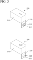
- FIG. 3 and FIG. 4 illustrate the binding member 300 provided in the terminal structure 200 in detail.
- the binding member 300 is provided in two types: a female binding member 310 and a male binding member 320.
- the female binding member 310 and the male binding member 320 complement each other, in other words, they form a male-female shape that can be fitted into one another.
- one embodiment of the binding member 300 illustrated shows that the female binding member 310 forms a groove 312, and the male binding member 320 forms a protrusion 322 that fits into the groove 312 of the female binding member 310.
- the cross-sections of the groove 312 and protrusion 322 in the drawings are circular, the shape of the groove 312 and protrusion 322 is not limited to the depicted form.
- the shape of the groove 312 and the protrusion 322 form an open shape rather than a closed shape.
- the groove 312 of the female binding member 310 and the protrusion 322 of the male binding member 320 are designed in a manner that they can be formed by bending a flat plate, and are characterized in that they form a dovetail structure in cross-section so that they can be elastically bound by spring action to exert a strong fastening force.
- the binding member 300 illustrated in FIGS. 3 and 4 has the female binding member 310 formed with a groove 312 that is open in the width direction W, and the male binding member 320 is formed with a protrusion 322 that protrudes in the width direction W. This means that the female binding member 310 and the male binding member 320 can be fastened and released along the width direction W.
- FIG. 5 illustrates a configuration where two secondary batteries 100 are interconnected through binding members 300 provided on their respective extension terminals 220. Since the binding member 300 is electrically connected to the extension terminal 220, when a plurality of secondary batteries 100 are connected to each other via the binding members 300, the plurality of secondary batteries 100 are electrically connected to each other.
- the binding member 300 can be manufactured as a separate component and attached to the extension terminal 220, or, as shown in the embodiment of the drawing, it is also possible for the binding member 300 to be integrally formed with the extension terminal 220.
- the two secondary batteries 100 are also interconnected along the width direction W. In this way, a plurality of secondary batteries 100 can be sequentially connected along the width direction W. In forming an electrical circuit, a plurality of secondary batteries 100 may be connected in series. Therefore, when a secondary battery 100 has its negative terminal 130 equipped with a female binding member 310 - or more precisely, when the extension terminal 220 connected to the negative terminal 130 is equipped with the female binding member 310 - a positive terminal 120 of an adjacent secondary battery should be equipped with a male binding member 320. In other words, adjacent secondary batteries 100 equipped with male and female binding members 300 having different polarity terminals.
- binding members 300 does not necessarily limit any one secondary battery 100 to having one female binding member 310 and one male binding member 320.
- all of the secondary batteries 100 may have the same male/female pattern of terminals of the same polarity, it is also possible to configure the secondary cells 100 such that some of the secondary batteries 100 have only female binding members 310 while others have only male binding members 320.
- a plurality of secondary batteries 100 may be connected in series along the width direction W, as long as the terminals of adjacent secondary batteries 100 with different polarities are provided with binding members 300 having different male-female properties.
- FIG. 6 illustrates a female binding member 310 and male binding member 320 according to the second embodiment of the present disclosure.
- the second embodiment of FIG. 6 is the same as the first embodiment described above in that a plurality of secondary batteries 100 can be connected in series along the width direction W, but there is a difference in the structure of interconnecting the female binding member 310 and the male binding member 320.
- the groove 312 of the female binding member 310 and the protrusion 322 of the male binding member 320 are facing the width direction W, so that the direction of the female-male coupling in the first embodiment is the width direction W of the secondary battery 100.
- the female binding member 310 includes a slot 314 open in the height direction H
- the male binding member 320 includes an insert 324 extending in the height direction H. That is, in the second embodiment, the plurality of secondary cells 100 are sequentially connected along the width direction W, but the female binding members 310 and male binding members 320 of adjacent secondary batteries 100 are engaged and disengaged along the height direction H.
- FIGS. 7 and 8 illustrate a structure in which a plurality of secondary batteries 100 are electrically connected using the binding member 300 of the second embodiment.
- FIGS. 7 and 8 illustrate a configuration in which two secondary batteries 100 are interconnected by male and female coupling in the height direction H through the binding members 300 provided on their respective extension terminals 220.
- the binding members 300 are electrically connected to the extension terminals 220, so that when the plurality of secondary batteries 100 are connected to each other through the binding members 300, the plurality of secondary batteries 100 are electrically connected to each other.
- the binding member 300 of the second embodiment greatly improves the stability of the electrical connection made by the direct connection of the binding member 300 when a plurality of secondary batteries 100 constitute a module or pack.
- the plurality of secondary batteries 100 may be connected one after another along the width direction W, so that the plurality of secondary batteries 100 may be connected in series to form an electrical circuit. And to connect in series, if the negative terminal 130 of one secondary battery 100 is provided with a female binding member 310, the positive terminal 120 of another adjacent secondary battery 100 should be provided with a male binding member 320. In other words, the adjacent secondary batteries 100 should have terminals with different polarities provided with binding members 300 having different male-female properties.
- the secondary battery 100 may be configured such that all secondary batteries 100 have the same male/female pattern of binding members 300 with terminals of the same polarity, or may be configured such that some secondary batteries 100 have only female connecting members 310 while other secondary batteries 100 have only male connecting members 320, as shown in FIG. 8 .
- binding member 300 of the second embodiment may also be manufactured as a separate member and bonded to the extension terminal 220, or the binding member 300 may be integrally formed with the extension terminal 220, as shown in the illustrated embodiment.
Landscapes
- Chemical & Material Sciences (AREA)
- Chemical Kinetics & Catalysis (AREA)
- Electrochemistry (AREA)
- General Chemical & Material Sciences (AREA)
- Engineering & Computer Science (AREA)
- Manufacturing & Machinery (AREA)
- Connection Of Batteries Or Terminals (AREA)
- Battery Mounting, Suspending (AREA)
- Sealing Battery Cases Or Jackets (AREA)
Abstract
Description
- This application claims the benefit of Korean Patent Application No.
KR 10-2022-0071220, filed on June 13, 2022 - The present disclosure relates to a secondary battery, and more particularly, to a prismatic secondary battery with an improved terminal structure that allows for easier modification of the arrangement of positive and/or negative terminals and facilitates electrical connection of multiple secondary batteries.
- Unlike primary batteries, secondary batteries are rechargeable and have been extensively researched and developed recently due to potential for miniaturization and high capacity applications. With increasing technological advancements and demand for mobile devices, as well as the growing prominence of electric vehicles and energy storage systems in response to environmental concerns, the demand for secondary batteries as an energy source is rapidly increasing.
- Depending on the shape of the battery case, secondary batteries are classified into coin-type batteries, cylindrical batteries, prismatic batteries, and pouch-type batteries. An electrode assembly, which is installed inside the battery case in secondary batteries, is a power generation element capable of charging and discharging. It has a laminated structure of electrodes and separators.
- Electrode assemblies can be broadly categorized into three types: a Jellyroll type, which involves winding a positive electrode and a negative electrode of an active material-coated sheet with a separator interposed therebetween; a stack type, where a plurality of positive electrodes and negative electrodes are sequentially stacked with a separator interposed therebetween; and a Stack & Folding type, where unit cells of a stack type are wound with a long separator film.
- When considering prismatic secondary batteries among the various types of secondary batteries, it is common for the positive and negative terminals to be arranged together on one side or to be placed on opposite sides. The placement of these terminals is determined by the design specifications of various devices that use prismatic secondary batteries. By adhering to these design specifications, the arrangement of the positive and negative terminals must be separately designed each time, even within the same form factor, which can be quite labor-intensive.
- In addition, to assemble a plurality of secondary batteries into modules or packs, electrical connections like busbars are required, and designing these busbars can also be complicated because, the busbar design depends on the arrangement structure of the positive and negative terminals.
- The background description provided herein is for the purpose of generally presenting context of the disclosure. Unless otherwise indicated herein, the materials described in this section are not prior art to the claims in this application and are not admitted to be prior art, or suggestions of the prior art, by inclusion in this section.
- The present disclosure provides a novel prismatic secondary battery that allows for easier modification of the arrangement structure of the positive and negative terminals without the need for separate design changes, and facilitates the electrical connection of multiple secondary batteries.
- However, the technical problems to be solved by the present disclosure are not limited to the above-described problem, and other problems not mentioned can be clearly understood by those skilled in the art from the following description.
- The present disclosure relates to a secondary battery. The secondary batteries may include a case having a plurality of surfaces including a first surface and a second surface; a positive terminal located on a surface of the case; a negative terminal located on the surface of the case and spaced apart from the positive terminal; and a terminal structure comprising a terminal body, an extension terminal, and a binding member, wherein: the terminal body includes a first face covering the positive terminal or the negative terminal and at least one second face extending from the first face; the extension terminal electrically connects to the positive terminal or the negative terminal and is located on the at least one second face of the terminal body; and the binding member is coupled to or integrally formed with the extension terminal.
- In one exemplary embodiment of the present disclosure, an extension wire electrically connecting the extension terminal to the positive terminal or negative terminal is not exposed outside of the terminal body.
- In addition, an extension wire electrically connecting the extension terminal to the positive terminal or negative terminal may be insulated outside of the terminal body.
- The terminal body may be coupled to the first surface of the case and the second surface of the case extending from the first surface of the case, and the extension terminal is exposed on the second surface of the case.
- In addition, a second terminal structure may be coupled to the positive or negative terminal.
- In one exemplary embodiment of the present disclosure, the binding member may be a male binding member or a female binding member.
- The male binding member or female binding member may be a first male binding member or a first female binding member; and the first male binding member or the first female binding member coupled to the positive terminal or the negative terminal may be further coupled to a second male binding member or a second female binding member coupled to a second negative terminal or a second positive terminal of an adjacent secondary battery.
- A secondary battery and an adjacent secondary battery may be aligned in a width direction; and the first male binding member or the first female binding member coupled to the second male binding member or the second female binding member may be coupled in the width direction.
- Here, the first female binding member may include a groove having an opening in the width direction, and the second male binding member may include a protrusion projecting in the width direction.
- In addition, the binding member may be integrally formed with the extension terminal.
- Meanwhile, in another exemplary embodiment of the present disclosure, a secondary battery and an adjacent secondary battery may be aligned in a width direction; and the first male binding member or the first female binding member coupled to the second male binding member or the second female binding member may be coupled in a height direction.
- In such exemplary embodiment, the first female binding member may include a slot open in the height direction, and the male binding member may include an insert extended in the height direction.
- Secondary batteries of the present disclosure having the aforementioned configurations can more easily change the arrangement structure of the positive and/or negative terminals by coupling the terminal structure to a corner portion of the top surface of the secondary battery. Therefore, it is possible to reduce the development and production costs of prismatic secondary batteries by more freely allowing the positioning of the terminal portions without affecting the existing inner cell manufacturing process.
- In addition, by providing binding members on the terminal structures, it is possible to directly connect these terminal structures to each other without using a separate busbar. For example, when connecting a plurality of secondary cells in a series circuit along the width direction, thereby simplifying the structure and reducing manufacturing costs when manufacturing battery modules or packs.
- However, advantageous effects of the present disclosure are not limited to those mentioned above, and other effects not mentioned will be apparent to one of ordinary skill in the art from the following description.
- The following drawings accompanying this specification illustrate preferred exemplary embodiments of the present disclosure and are intended to serve as a further understanding of the technical ideas of the present disclosure in conjunction with the detailed description that follows, so the present disclosure is not to be construed as limited to what is shown in such drawings.
-
FIG. 1 is a perspective view of a secondary battery according to the present disclosure. -
FIG. 2 is a perspective view illustrating the coupling structure of a secondary battery and a terminal structure according to the present disclosure. -
FIG. 3 is a drawing illustrating an embodiment of a female binding member. -
FIG. 4 is a drawing illustrating an embodiment of a male binding member. -
FIG. 5 is a drawing illustrating a structure in which two secondary batteries are electrically connected to each other through a binding member. -
FIG. 6 is a drawing illustrating male and female binding members according to another embodiment of the present disclosure. -
FIG. 7 is a drawing illustrating a structure in which a plurality of secondary batteries are electrically connected using the binding member ofFIG. 6 . -
FIG. 8 is a drawing illustrating a structure in which a plurality of secondary batteries are electrically connected using the binding member ofFIG. 6 . - The present disclosure may have various modifications and various examples, while specific examples are illustrated in the drawings and described in detail in the description.
- However, it should be understood that the present disclosure is not limited to specific embodiments, and includes all modifications, equivalents or alternatives within the spirit and technical scope of the present disclosure.
- The terms "comprise," "include" and "have" are used herein to designate the presence of characteristics, numbers, steps, actions, components or members described in the specification or a combination thereof, and it should be understood that the possibility of the presence or addition of one or more other characteristics, numbers, steps, actions, components, members or a combination thereof is not excluded in advance.
- In addition, when a part of a layer, a film, a region or a plate is disposed "on" another part, this includes not only a case in which one part is disposed "directly on" another part, but a case in which a third part is interposed there between. In contrast, when a part of a layer, a film, a region or a plate is disposed "under" another part, this includes not only a case in which one part is disposed "directly under" another part, but a case in which a third part is interposed there between. In addition, in this application, "on" may include not only a case of disposed on an upper part but also a case of disposed on a lower part.
- The present disclosure relates to a secondary battery, specifically to a secondary battery with positive and negative terminals spaced apart on the top surface of a hexahedral shaped cell case.
- A secondary battery according to the present disclosure, in one example, has a terminal structure coupled to at least one top surface corner of the battery case. The terminal structure includes a terminal body coupled to a top surface of the battery case and one or more faces extending from the top surface while enclosing the positive or negative terminal so that it is not exposed, and an extension terminal electrically connected to the positive or negative terminal and exposed to any one surface of the terminal bodies except the top surface.
- In addition, the terminal structure includes a binding member provided on an extension terminal. The binding member is a member that directly connects the extension terminals of the terminal structure facing each other, and a plurality of secondary cells can be electrically connected by the binding member.
- In this way, the secondary battery of the present disclosure including the terminal structure can be freely changed to meet the needs of the user without any design changes by simply applying the terminal structure to the position of the positive and negative terminals arranged on the top surface of the battery case, thereby reducing the production cost of the prismatic secondary battery.
- In addition, by providing a binding member on the terminal structure, it is possible to directly connect the terminal structure to each other without a separate busbar when connecting a plurality of secondary cells in a series circuit along the width direction, thereby simplifying the structure and reducing manufacturing costs when manufacturing battery modules or packs.
- Below, detailed embodiments of the secondary battery according to the present disclosure is described with reference to the attached drawings. Furthermore, terms used in the following description, such as front and back, left and right, or top and bottom, which specify spatial positional relationships, are based on the attached drawings unless specifically defined otherwise.
-
FIG. 1 is a perspective view of asecondary battery 100 according to the present disclosure, andFIG. 2 is a perspective view illustrating the coupling structure between thesecondary battery 100 and theterminal structure 200 according to the present disclosure. - Referring to
FIGS. 1 and2 , the present disclosure pertains to asecondary battery 100, specifically a prismaticsecondary battery 100 where thepositive terminal 120 and thenegative terminal 130 are spaced apart and arranged on the top surface of abattery case 110 that forms a hexahedral shape. Here, the prismaticsecondary battery 100 depicted in the drawings is merely one example, and the ratios of width, depth, and height can vary. However, for the convenience of the description, the directions of front and back, and top, bottom, left, and right are referred to based on the attached drawings. For instance, a side on which thepositive terminal 120 and thenegative terminal 130 are disposed is called the top surface, and its opposite side is called the bottom surface. - Additionally, the coordinate axes displayed in
FIGS. 1 and2 designate the width direction W, thickness direction T, and height direction H of the secondary battery. The width direction W indicates the direction intersecting both thepositive terminal 120 and thenegative terminal 130. The thickness direction T indicates the depth direction perpendicular to the width direction W, and the height direction H designates the direction perpendicular to both the width direction W and the thickness direction T. - The
secondary battery 100 of the present disclosure includes aterminal structure 200. Theterminal structure 200 is a hinge-shaped structure that attaches to at least one corner of the top surface of thebattery case 110 and includes aterminal body 210 and anextension terminal 220. - The
terminal body 210 refers to the body of theterminal structure 200 that is coupled to the top surface of thebattery case 110 and one or more surfaces (such as a side, front, rear, etc.) extending from the top surface while enclosing thepositive terminal 120 or thenegative terminal 130 from being exposed to the outside.
Theextension terminal 220 is a connection terminal that is electrically connected to thepositive terminal 120 or thenegative terminal 130 and is exposed on a surface of theterminal body 210, excluding the top surface. In other words, since thepositive terminal 120 and thenegative terminal 130 are covered by theterminal body 210 and are not exposed, theextension terminal 220 serves the function of a newpositive terminal 120 andnegative terminal 130 located on another surface other than the top surface. - Therefore, the
secondary battery 100 of the present disclosure allows for the freedom to change the positions of thepositive terminal 120 and thenegative terminal 130 located on the top surface of thebattery case 110 simply by applying theterminal structure 200 without any separate design modifications. Consequently, the present disclosure enables the convenient alteration of the positions of thepositive terminal 120 and thenegative terminal 130 using theterminal structure 200 for a prismaticsecondary battery 100 with the same form factor, so the production cost of the prismaticsecondary battery 100 can be reduced. - Furthermore, the
terminal structure 200 includes a bindingmember 300 provided on theextension terminal 220. The bindingmember 300 is a component that directly connects theextension terminals 220 of theterminal structures 200 facing each other. With the bindingmember 300, a plurality ofsecondary batteries 100 can be electrically connected. - In this way, by equipping the
terminal structure 200 with the bindingmember 300, it becomes possible to directly connect theterminal structures 200 to each other. Therefore, a plurality ofsecondary batteries 100 can be electrically interconnected directly through the bindingmembers 300 without the need for a separate bus bar. As a result, it simplifies the structure and reduces the manufacturing cost when producing battery modules or packs. - Moreover, the
terminal structure 200 can be attached to thepositive terminal 120 and thenegative terminal 130 one by one. As a result, thepositive terminal 120 and thenegative terminal 130 are positioned on opposing side surfaces. In other words, thepositive terminal 120 and thenegative terminal 130, which were originally arranged together on the top surface of thebattery case 110, are relocated to adjacent side surfaces. Consequently, the prismaticsecondary battery 100, initially designed as a unidirectional secondary battery, is transformed into a bidirectional secondary battery. - Additionally, the
terminal structure 200 can be attached to the completedsecondary battery 100. Or, as depicted inFIG. 2 , it is possible to manufacture by first coupling theterminal structure 200 to thecap plate 150 which forms the top surface of thebattery case 110 before inserting theelectrode assembly 160 into thebattery case 110. -
FIG. 3 andFIG. 4 illustrate the bindingmember 300 provided in theterminal structure 200 in detail. In one embodiment of the present disclosure, the bindingmember 300 is provided in two types: a female bindingmember 310 and a male bindingmember 320. The female bindingmember 310 and the male bindingmember 320 complement each other, in other words, they form a male-female shape that can be fitted into one another. - In
FIG. 3 , one embodiment of the bindingmember 300 illustrated shows that the female bindingmember 310 forms agroove 312, and the male bindingmember 320 forms aprotrusion 322 that fits into thegroove 312 of the female bindingmember 310. Although the cross-sections of thegroove 312 andprotrusion 322 in the drawings are circular, the shape of thegroove 312 andprotrusion 322 is not limited to the depicted form. - In the embodiment of
FIG. 4 , the shape of thegroove 312 and theprotrusion 322 form an open shape rather than a closed shape. Specifically, thegroove 312 of the female bindingmember 310 and theprotrusion 322 of the male bindingmember 320 are designed in a manner that they can be formed by bending a flat plate, and are characterized in that they form a dovetail structure in cross-section so that they can be elastically bound by spring action to exert a strong fastening force. - Here, the binding
member 300 illustrated inFIGS. 3 and4 has the female bindingmember 310 formed with agroove 312 that is open in the width direction W, and the male bindingmember 320 is formed with aprotrusion 322 that protrudes in the width direction W. This means that the female bindingmember 310 and the male bindingmember 320 can be fastened and released along the width direction W. -
FIG. 5 illustrates a configuration where twosecondary batteries 100 are interconnected throughbinding members 300 provided on theirrespective extension terminals 220. Since the bindingmember 300 is electrically connected to theextension terminal 220, when a plurality ofsecondary batteries 100 are connected to each other via the bindingmembers 300, the plurality ofsecondary batteries 100 are electrically connected to each other. The bindingmember 300 can be manufactured as a separate component and attached to theextension terminal 220, or, as shown in the embodiment of the drawing, it is also possible for the bindingmember 300 to be integrally formed with theextension terminal 220. - Referring back to
FIG. 5 , given that the female bindingmember 310 and the male bindingmember 320 can be engaged and disengaged along the width direction W, the twosecondary batteries 100 are also interconnected along the width direction W. In this way, a plurality ofsecondary batteries 100 can be sequentially connected along the width direction W. In forming an electrical circuit, a plurality ofsecondary batteries 100 may be connected in series. Therefore, when asecondary battery 100 has itsnegative terminal 130 equipped with a female binding member 310 - or more precisely, when theextension terminal 220 connected to thenegative terminal 130 is equipped with the female binding member 310 - apositive terminal 120 of an adjacent secondary battery should be equipped with a male bindingmember 320. In other words, adjacentsecondary batteries 100 equipped with male and femalebinding members 300 having different polarity terminals. - However, this combination of binding
members 300 does not necessarily limit any onesecondary battery 100 to having one female bindingmember 310 and onemale binding member 320. Of course, while it is common for all of thesecondary batteries 100 to have the same male/female pattern of terminals of the same polarity, it is also possible to configure thesecondary cells 100 such that some of thesecondary batteries 100 have only femalebinding members 310 while others have only male bindingmembers 320. In other words, a plurality ofsecondary batteries 100 may be connected in series along the width direction W, as long as the terminals of adjacentsecondary batteries 100 with different polarities are provided withbinding members 300 having different male-female properties. -
FIG. 6 illustrates a female bindingmember 310 and male bindingmember 320 according to the second embodiment of the present disclosure. - The second embodiment of
FIG. 6 is the same as the first embodiment described above in that a plurality ofsecondary batteries 100 can be connected in series along the width direction W, but there is a difference in the structure of interconnecting the female bindingmember 310 and the male bindingmember 320. - In the first embodiment shown in
FIGS. 1 to 5 , thegroove 312 of the female bindingmember 310 and theprotrusion 322 of the male bindingmember 320 are facing the width direction W, so that the direction of the female-male coupling in the first embodiment is the width direction W of thesecondary battery 100. - In comparison, in the second embodiment of
FIG. 6 , the female bindingmember 310 includes aslot 314 open in the height direction H, and the male bindingmember 320 includes aninsert 324 extending in the height direction H. That is, in the second embodiment, the plurality ofsecondary cells 100 are sequentially connected along the width direction W, but the femalebinding members 310 and male bindingmembers 320 of adjacentsecondary batteries 100 are engaged and disengaged along the height direction H. -
FIGS. 7 and 8 illustrate a structure in which a plurality ofsecondary batteries 100 are electrically connected using the bindingmember 300 of the second embodiment. -
FIGS. 7 and 8 illustrate a configuration in which twosecondary batteries 100 are interconnected by male and female coupling in the height direction H through the bindingmembers 300 provided on theirrespective extension terminals 220. As in the case of the first embodiment, the bindingmembers 300 are electrically connected to theextension terminals 220, so that when the plurality ofsecondary batteries 100 are connected to each other through the bindingmembers 300, the plurality ofsecondary batteries 100 are electrically connected to each other. - In particular, in the binding
member 300 of the second embodiment, the female bindingmember 310 and the male bindingmember 320 of the adjacentsecondary battery 100 are engaged and disengaged along the height direction H, so that the female bindingmember 310 and the male bindingmember 320, once engaged, are not disengageable in the width direction W. Therefore, there is little concern that the engaged bindingmember 300 will be disengaged from each other even if thesecondary battery 100 is subjected to fluctuations or vibrations. In this respect, the bindingmember 300 according to the second embodiment greatly improves the stability of the electrical connection made by the direct connection of the bindingmember 300 when a plurality ofsecondary batteries 100 constitute a module or pack. - In the second embodiment, the plurality of
secondary batteries 100 may be connected one after another along the width direction W, so that the plurality ofsecondary batteries 100 may be connected in series to form an electrical circuit. And to connect in series, if thenegative terminal 130 of onesecondary battery 100 is provided with a female bindingmember 310, thepositive terminal 120 of another adjacentsecondary battery 100 should be provided with a male bindingmember 320. In other words, the adjacentsecondary batteries 100 should have terminals with different polarities provided withbinding members 300 having different male-female properties. - Thus, as shown in
FIG. 7 , thesecondary battery 100 may be configured such that allsecondary batteries 100 have the same male/female pattern of bindingmembers 300 with terminals of the same polarity, or may be configured such that somesecondary batteries 100 have only female connectingmembers 310 while othersecondary batteries 100 have only male connectingmembers 320, as shown inFIG. 8 . - Note that the binding
member 300 of the second embodiment may also be manufactured as a separate member and bonded to theextension terminal 220, or the bindingmember 300 may be integrally formed with theextension terminal 220, as shown in the illustrated embodiment. - Various principles have been described above in more detail through the drawings and embodiments. However, the configurations described in the drawings or the embodiments in the specification are merely embodiments of the present disclosure and do not represent all the technical ideas of the present disclosure. Thus, it is to be understood that there may be various equivalents and variations in place of them at the time of filing the present application.
-
- 100: SECONDARY BATTERY 110: BATTERY CASE
- 120: POSITIVE TERMINAL 130: NEGATIVE TERMINAL
- 140: VENTING PART 150: CAP PLATE
- 160: ELECTRODE ASSEMBLY 200: TERMINAL STRUCTURE
- 210: TERMINAL BODY 220: EXTENSION TERMINAL
- 230: EXTENSION WIRE 300: BINDING MEMBER
- 310: FEMALE BINDING MEMBER 312: GROOVE
- 314: SLOT 320: MALE BINDING MEMBER
- 322: PROTRUSION 324: INSERT
- W: WIDTH DIRECTION T: THICKNESS DIRECTION
- H: HEIGHT DIRECTION
Claims (12)
- A secondary battery comprising:a case having a plurality of surfaces including a first surface and a second surface;a positive terminal located on a surface of the case;a negative terminal located on the surface of the case and spaced apart from the positive terminal; anda terminal structure comprising a terminal body, an extension terminal, and a binding member, wherein:the terminal body includes a first face covering the positive terminal or the negative terminal and at least one second face extending from the first face;the extension terminal electrically connects to the positive terminal or the negative terminal and is located on the at least one second face of the terminal body; andthe binding member is coupled to or integrally formed with the extension terminal.
- The secondary battery of claim 1, further comprising:
an extension wire electrically connecting the extension terminal to the positive terminal or the negative terminal, wherein the extension wire is not exposed outside of the terminal body. - The secondary battery of claim 1, further comprising:
an extension wire electrically connecting the extension terminal to the positive terminal or the negative terminal, wherein the extension wire is insulated outside of the terminal body. - The secondary battery of claim 1, wherein:the terminal body is coupled to the first surface of the case and the second surface of the case extending from the first surface of the case, andthe extension terminal is exposed on the second surface of the case.
- The secondary battery of claim 4, further comprising:
a second terminal structure covering the positive terminal or the negative terminal. - The secondary battery of claim 4, wherein:
the binding member is a male binding member or a female binding member. - The secondary battery of claim 6, wherein:the male binding member or the female binding member is a first male binding member or a first female binding member; andthe first male binding member or the first female binding member coupled to the positive terminal or the negative terminal is further coupled to a second male binding member or a second female binding member coupled to a second negative terminal or a second positive terminal of an adjacent secondary battery.
- The secondary battery of claim 7, wherein:the secondary battery and the adjacent secondary battery are aligned in a width direction; andthe first male binding member or the first female binding member coupled to the second male binding member or the second female binding member are coupled in the width direction.
- The secondary battery of claim 8, wherein:the first female binding member comprises a groove having an opening in the width direction, andthe second male binding member comprises a protrusion projecting in the width direction.
- The secondary battery of claim 1, wherein:
the binding member is integrally formed with the extension terminal. - The secondary battery of claim 7, wherein:the secondary battery and the adjacent secondary battery are aligned in a width direction; andthe first male binding member or the first female binding member coupled to the second male binding member or the second female binding member are coupled in a height direction.
- The secondary battery of claim 11, wherein:the first female binding member comprises a slot open in the height direction, andthe second male binding member comprises an insert extended in the height direction.
Applications Claiming Priority (2)
| Application Number | Priority Date | Filing Date | Title |
|---|---|---|---|
| KR1020220071220A KR20230171100A (en) | 2022-06-13 | 2022-06-13 | Secondary battery having improved terminal structure |
| PCT/KR2023/007980 WO2023243949A1 (en) | 2022-06-13 | 2023-06-09 | Secondary battery with improved terminal structure |
Publications (2)
| Publication Number | Publication Date |
|---|---|
| EP4425685A1 true EP4425685A1 (en) | 2024-09-04 |
| EP4425685A4 EP4425685A4 (en) | 2025-03-05 |
Family
ID=89191508
Family Applications (1)
| Application Number | Title | Priority Date | Filing Date |
|---|---|---|---|
| EP23824166.5A Pending EP4425685A4 (en) | 2022-06-13 | 2023-06-09 | SECONDARY BATTERY WITH IMPROVED CONNECTION STRUCTURE |
Country Status (6)
| Country | Link |
|---|---|
| US (1) | US20250038376A1 (en) |
| EP (1) | EP4425685A4 (en) |
| JP (1) | JP7831913B2 (en) |
| KR (1) | KR20230171100A (en) |
| CN (1) | CN118369816A (en) |
| WO (1) | WO2023243949A1 (en) |
Family Cites Families (13)
| Publication number | Priority date | Publication date | Assignee | Title |
|---|---|---|---|---|
| JP4416266B2 (en) * | 1999-10-08 | 2010-02-17 | パナソニック株式会社 | Sealed prismatic battery |
| KR101222371B1 (en) * | 2010-11-12 | 2013-01-16 | 로베르트 보쉬 게엠베하 | Terminal of rechargeable battery, method of assembling the terminal of rechargeable battery, rechargeable battery module and method of assembling the same |
| JP2012204296A (en) * | 2011-03-28 | 2012-10-22 | Gs Yuasa Corp | Battery pack, single battery, and cap |
| JP2012252924A (en) * | 2011-06-03 | 2012-12-20 | Primearth Ev Energy Co Ltd | Manufacturing method of battery pack |
| KR101627631B1 (en) * | 2012-04-12 | 2016-06-07 | 삼성에스디아이 주식회사 | Rechargeable battery and module thereof |
| KR20140094207A (en) * | 2013-01-21 | 2014-07-30 | 삼성에스디아이 주식회사 | Rechargeable battery module |
| JP6243197B2 (en) * | 2013-11-12 | 2017-12-06 | 矢崎総業株式会社 | Battery cover |
| JP2015179578A (en) * | 2014-03-18 | 2015-10-08 | 株式会社リチウムエナジージャパン | Storage element and power supply module |
| KR102408824B1 (en) * | 2015-06-22 | 2022-06-13 | 삼성에스디아이 주식회사 | Rechargeable battery and rechargeable battery module |
| JP2017216088A (en) * | 2016-05-30 | 2017-12-07 | 株式会社東芝 | Battery pack |
| US11394086B2 (en) * | 2017-09-27 | 2022-07-19 | Kabushiki Kaisha Toshiba | Battery module and connection member |
| KR102578860B1 (en) | 2018-02-27 | 2023-09-13 | 삼성에스디아이 주식회사 | Rechargeable battery |
| JP7114731B2 (en) * | 2018-10-31 | 2022-08-08 | ビークルエナジージャパン株式会社 | battery module |
-
2022
- 2022-06-13 KR KR1020220071220A patent/KR20230171100A/en active Pending
-
2023
- 2023-06-09 JP JP2024532547A patent/JP7831913B2/en active Active
- 2023-06-09 WO PCT/KR2023/007980 patent/WO2023243949A1/en not_active Ceased
- 2023-06-09 EP EP23824166.5A patent/EP4425685A4/en active Pending
- 2023-06-09 US US18/718,375 patent/US20250038376A1/en active Pending
- 2023-06-09 CN CN202380015018.6A patent/CN118369816A/en active Pending
Also Published As
| Publication number | Publication date |
|---|---|
| WO2023243949A1 (en) | 2023-12-21 |
| JP2024542707A (en) | 2024-11-15 |
| JP7831913B2 (en) | 2026-03-17 |
| CN118369816A (en) | 2024-07-19 |
| KR20230171100A (en) | 2023-12-20 |
| US20250038376A1 (en) | 2025-01-30 |
| EP4425685A4 (en) | 2025-03-05 |
Similar Documents
| Publication | Publication Date | Title |
|---|---|---|
| CN108604710A (en) | Laminated non-aqueous electrolyte secondary battery | |
| JP2021501444A (en) | Battery module | |
| US20260100483A1 (en) | Cell, battery, and electric device | |
| JP7307069B2 (en) | Fixing structure of battery module | |
| US20260038990A1 (en) | Prismatic secondary battery having improved connection structure in upper case | |
| WO2024037361A1 (en) | Battery cell, battery, and electrical device | |
| CN116134669B (en) | Battery, electrical equipment, method and equipment for preparing battery | |
| EP4376207B1 (en) | Secondary battery with improved connection structure | |
| EP4425685A1 (en) | Secondary battery with improved terminal structure | |
| EP4518005A1 (en) | Terminal structure assembly integrally including busbar | |
| JP7819432B2 (en) | Secondary battery with improved terminal structure | |
| EP4421969A1 (en) | Secondary battery having improved terminal structure | |
| JP7800999B2 (en) | Battery module including upper and lower end separated bus bar frame and method for assembling same | |
| JP7835900B2 (en) | Battery module | |
| EP4704231A1 (en) | Battery assembly and battery pack | |
| US20260011752A1 (en) | Battery, Battery Pack and Vehicle Including the Same | |
| CN118738773A (en) | Battery device including bus bar assembly and method for manufacturing battery device | |
| CN120188334A (en) | Battery module and battery pack including the battery module |
Legal Events
| Date | Code | Title | Description |
|---|---|---|---|
| STAA | Information on the status of an ep patent application or granted ep patent |
Free format text: STATUS: THE INTERNATIONAL PUBLICATION HAS BEEN MADE |
|
| PUAI | Public reference made under article 153(3) epc to a published international application that has entered the european phase |
Free format text: ORIGINAL CODE: 0009012 |
|
| STAA | Information on the status of an ep patent application or granted ep patent |
Free format text: STATUS: REQUEST FOR EXAMINATION WAS MADE |
|
| 17P | Request for examination filed |
Effective date: 20240527 |
|
| AK | Designated contracting states |
Kind code of ref document: A1 Designated state(s): AL AT BE BG CH CY CZ DE DK EE ES FI FR GB GR HR HU IE IS IT LI LT LU LV MC ME MK MT NL NO PL PT RO RS SE SI SK SM TR |
|
| A4 | Supplementary search report drawn up and despatched |
Effective date: 20250204 |
|
| RIC1 | Information provided on ipc code assigned before grant |
Ipc: H01M 50/55 20210101ALI20250129BHEP Ipc: H01M 50/503 20210101ALI20250129BHEP Ipc: H01M 50/50 20210101ALI20250129BHEP Ipc: H01M 50/103 20210101ALI20250129BHEP Ipc: H01M 50/15 20210101ALI20250129BHEP Ipc: H01M 50/553 20210101ALI20250129BHEP Ipc: H01M 50/531 20210101AFI20250129BHEP |
|
| DAV | Request for validation of the european patent (deleted) | ||
| DAX | Request for extension of the european patent (deleted) | ||
| STAA | Information on the status of an ep patent application or granted ep patent |
Free format text: STATUS: EXAMINATION IS IN PROGRESS |
|
| 17Q | First examination report despatched |
Effective date: 20251118 |