EP4425675A1 - Battery module that integrates gas venting channel and cooling channel, battery pack including same, and method for manufacturing battery module - Google Patents
Battery module that integrates gas venting channel and cooling channel, battery pack including same, and method for manufacturing battery module Download PDFInfo
- Publication number
- EP4425675A1 EP4425675A1 EP23812030.7A EP23812030A EP4425675A1 EP 4425675 A1 EP4425675 A1 EP 4425675A1 EP 23812030 A EP23812030 A EP 23812030A EP 4425675 A1 EP4425675 A1 EP 4425675A1
- Authority
- EP
- European Patent Office
- Prior art keywords
- cooling
- channel
- battery module
- gas
- venting
- Prior art date
- Legal status (The legal status is an assumption and is not a legal conclusion. Google has not performed a legal analysis and makes no representation as to the accuracy of the status listed.)
- Pending
Links
Images


Classifications
-
- H—ELECTRICITY
- H01—ELECTRIC ELEMENTS
- H01M—PROCESSES OR MEANS, e.g. BATTERIES, FOR THE DIRECT CONVERSION OF CHEMICAL ENERGY INTO ELECTRICAL ENERGY
- H01M10/00—Secondary cells; Manufacture thereof
- H01M10/60—Heating or cooling; Temperature control
- H01M10/65—Means for temperature control structurally associated with the cells
- H01M10/655—Solid structures for heat exchange or heat conduction
- H01M10/6556—Solid parts with flow channel passages or pipes for heat exchange
-
- H—ELECTRICITY
- H01—ELECTRIC ELEMENTS
- H01M—PROCESSES OR MEANS, e.g. BATTERIES, FOR THE DIRECT CONVERSION OF CHEMICAL ENERGY INTO ELECTRICAL ENERGY
- H01M10/00—Secondary cells; Manufacture thereof
- H01M10/60—Heating or cooling; Temperature control
- H01M10/61—Types of temperature control
- H01M10/613—Cooling or keeping cold
-
- H—ELECTRICITY
- H01—ELECTRIC ELEMENTS
- H01M—PROCESSES OR MEANS, e.g. BATTERIES, FOR THE DIRECT CONVERSION OF CHEMICAL ENERGY INTO ELECTRICAL ENERGY
- H01M10/00—Secondary cells; Manufacture thereof
- H01M10/60—Heating or cooling; Temperature control
- H01M10/64—Heating or cooling; Temperature control characterised by the shape of the cells
- H01M10/647—Prismatic or flat cells, e.g. pouch cells
-
- H—ELECTRICITY
- H01—ELECTRIC ELEMENTS
- H01M—PROCESSES OR MEANS, e.g. BATTERIES, FOR THE DIRECT CONVERSION OF CHEMICAL ENERGY INTO ELECTRICAL ENERGY
- H01M10/00—Secondary cells; Manufacture thereof
- H01M10/60—Heating or cooling; Temperature control
- H01M10/65—Means for temperature control structurally associated with the cells
- H01M10/656—Means for temperature control structurally associated with the cells characterised by the type of heat-exchange fluid
- H01M10/6567—Liquids
- H01M10/6568—Liquids characterised by flow circuits, e.g. loops, located externally to the cells or cell casings
-
- H—ELECTRICITY
- H01—ELECTRIC ELEMENTS
- H01M—PROCESSES OR MEANS, e.g. BATTERIES, FOR THE DIRECT CONVERSION OF CHEMICAL ENERGY INTO ELECTRICAL ENERGY
- H01M50/00—Constructional details or processes of manufacture of the non-active parts of electrochemical cells other than fuel cells, e.g. hybrid cells
- H01M50/20—Mountings; Secondary casings or frames; Racks, modules or packs; Suspension devices; Shock absorbers; Transport or carrying devices; Holders
- H01M50/204—Racks, modules or packs for multiple batteries or multiple cells
-
- H—ELECTRICITY
- H01—ELECTRIC ELEMENTS
- H01M—PROCESSES OR MEANS, e.g. BATTERIES, FOR THE DIRECT CONVERSION OF CHEMICAL ENERGY INTO ELECTRICAL ENERGY
- H01M50/00—Constructional details or processes of manufacture of the non-active parts of electrochemical cells other than fuel cells, e.g. hybrid cells
- H01M50/20—Mountings; Secondary casings or frames; Racks, modules or packs; Suspension devices; Shock absorbers; Transport or carrying devices; Holders
- H01M50/271—Lids or covers for the racks or secondary casings
-
- H—ELECTRICITY
- H01—ELECTRIC ELEMENTS
- H01M—PROCESSES OR MEANS, e.g. BATTERIES, FOR THE DIRECT CONVERSION OF CHEMICAL ENERGY INTO ELECTRICAL ENERGY
- H01M50/00—Constructional details or processes of manufacture of the non-active parts of electrochemical cells other than fuel cells, e.g. hybrid cells
- H01M50/30—Arrangements for facilitating escape of gases
- H01M50/35—Gas exhaust passages comprising elongated, tortuous or labyrinth-shaped exhaust passages
- H01M50/367—Internal gas exhaust passages forming part of the battery cover or case; Double cover vent systems
-
- H—ELECTRICITY
- H01—ELECTRIC ELEMENTS
- H01M—PROCESSES OR MEANS, e.g. BATTERIES, FOR THE DIRECT CONVERSION OF CHEMICAL ENERGY INTO ELECTRICAL ENERGY
- H01M2220/00—Batteries for particular applications
- H01M2220/20—Batteries in motive systems, e.g. vehicle, ship, plane
-
- H—ELECTRICITY
- H01—ELECTRIC ELEMENTS
- H01M—PROCESSES OR MEANS, e.g. BATTERIES, FOR THE DIRECT CONVERSION OF CHEMICAL ENERGY INTO ELECTRICAL ENERGY
- H01M50/00—Constructional details or processes of manufacture of the non-active parts of electrochemical cells other than fuel cells, e.g. hybrid cells
- H01M50/20—Mountings; Secondary casings or frames; Racks, modules or packs; Suspension devices; Shock absorbers; Transport or carrying devices; Holders
- H01M50/204—Racks, modules or packs for multiple batteries or multiple cells
- H01M50/207—Racks, modules or packs for multiple batteries or multiple cells characterised by their shape
- H01M50/211—Racks, modules or packs for multiple batteries or multiple cells characterised by their shape adapted for pouch cells
-
- Y—GENERAL TAGGING OF NEW TECHNOLOGICAL DEVELOPMENTS; GENERAL TAGGING OF CROSS-SECTIONAL TECHNOLOGIES SPANNING OVER SEVERAL SECTIONS OF THE IPC; TECHNICAL SUBJECTS COVERED BY FORMER USPC CROSS-REFERENCE ART COLLECTIONS [XRACs] AND DIGESTS
- Y02—TECHNOLOGIES OR APPLICATIONS FOR MITIGATION OR ADAPTATION AGAINST CLIMATE CHANGE
- Y02E—REDUCTION OF GREENHOUSE GAS [GHG] EMISSIONS, RELATED TO ENERGY GENERATION, TRANSMISSION OR DISTRIBUTION
- Y02E60/00—Enabling technologies; Technologies with a potential or indirect contribution to GHG emissions mitigation
- Y02E60/10—Energy storage using batteries
Definitions
- the present disclosure relates to a battery module, and more particularly to, a battery module in which a cooling device for dissipating heat generated from the battery module and a gas venting device for gas venting in the event of thermal runaway are formed into a single component.
- secondary batteries are being used as a source of energy for not only small multifunctional products such as wireless mobile devices or wearable devices but also electric vehicles and hybrid electric vehicles proposed as an alternative to gasoline vehicles and diesel vehicles or energy storage systems (ESSs).
- ESSs energy storage systems
- Lithium secondary batteries used widely in recent years have the operating voltage of about 2.5V to 4.5V of each battery. Accordingly, electric vehicles or energy storage systems requiring large capacity and high output use, as a source of energy, a battery module including lithium secondary batteries connected in series and/or in parallel and a battery pack including battery modules connected in series and/or in parallel.
- the number of lithium secondary batteries in one battery module or the number of battery modules in one battery pack may increase according to the output or capacity of the battery pack required for electric vehicles.
- venting gas may be produced in the lithium secondary batteries, and when degradation gets worse, flames and high temperature sparks including electrode active materials and aluminum particles may occur, and the flames and high temperature sparks may erupt from the corresponding battery module along with venting gas.
- the erupting flames and high temperature sparks cause thermal damage to the other battery modules adjacent to the battery module in which the fire occurred, accelerating the spread of the fire to the other battery modules.
- the battery module includes a gas venting device and a cooling device.
- the gas venting device 2 may be configured such that it is mounted on top of the battery module 1 and the inside of the gas venting device 2 is in communication with the inside of the battery module 1.
- the gas venting device 2 serves to vent gas while suppressing leakage of flames in the event of fire in the battery module 1.
- the cooling device 3 is mounted on bottom of the battery module 1, has a flow channel for the flow of cooling water inside, and is configured to absorb heat from battery cells by indirect contact between the cooling water and the battery cells.
- the present disclosure is designed to solve the above-described problem, and therefore the present disclosure is directed to providing a battery module with a new single component into which a gas venting device and a cooling device are combined and a method for manufacturing the battery module.
- a battery module may include a plurality of battery cells; a module case accommodating the plurality of battery cells and having a gas venting hole on at least one side; and a cooling and venting unit including a gas venting channel and a cooling channel integrally formed in a single body, and disposed on an outer side of the module case, wherein the gas venting channel forms a movement path of gas in communication with the gas venting hole, and the cooling channel forms a movement path of a cooling medium.
- the cooling and venting unit may include a channel plate having the gas venting channel in a first surface and the cooling channel in a second surface opposite the first surface; and a cover plate covering any one of the first surface and the second surface and coupled to the channel plate.
- the first surface may have a embossed portion convexly protruding in a predetermined area, and the gas venting channel may be provided in an area surrounded by the embossed portion.
- the cooling channel may be formed opposite the embossed portion of the first surface in the second surface, and may be a region which is concavely recessed from a surface of the second surface along a shape of the embossed portion.
- the channel plate may be made of a metal.
- the cover plate may cover the first surface of the channel plate, and the second surface of the channel plate may be disposed facing an outer surface of the module case.
- the cooling and venting unit may have a gas inlet, through which a portion of the channel plate contacting the outer surface of the module case is open in a thicknesswise direction, so that the gas inlet matches the gas venting hole of the module case in a vertical direction.
- the gas inlet and the gas venting channel may be in communication with each other, and the gas venting channel may have a path which is extended in a serpentine pattern from one end of the channel plate to the other end and a gas outlet in communication with outside may be provided at the other end.
- the cooling and venting unit may include a cooling medium inlet on one side of the cooling channel and a cooling medium outlet on the other side of the cooling channel.
- the cooling medium inlet or the cooling medium outlet may be formed by a gap between a preset portion of edges of the second surface and the outer surface of the module case.
- the cooling and venting unit may be coupled to a top of the module case.
- the cooling and venting unit may be coupled to at least one side of the module case.
- a battery pack including the above-described battery module.
- a method for manufacturing the battery module including: receiving the plurality of battery cells in the module case; preparing the cooling and venting unit; and coupling the cooling and venting unit to an outer surface of the module case, wherein the preparing of the cooling and venting unit includes a stamping process of placing a flat metal plate between an upper mold and a lower mold, and pressing the metal plate in a vertical direction using the upper mold and the lower mold to form the channel plate including the gas venting channel in a surface of the metal plate and the cooling channel in an opposite surface of the metal plate so as to form the channel plate.
- the preparing of the cooling and venting unit may further include a process of attaching the cover plate to one surface of the channel plate.
- the coupling may include a process of attaching the cooling and venting unit to the outer surface of the module case having the gas venting hole using at least one coupling method of welding, bolting, hooking or adhesion.
- the battery module with the new single component into which the gas venting device and the cooling device are combined.
- the cooling and venting unit into which the gas venting device and the cooling device are combined according to the present disclosure may simplify the assembly process of the battery module and reduce the cost and time and the volume of the final product.
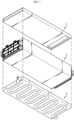
- FIG. 2 is a partial exploded perspective view of a battery module except a cooling and venting unit according to an embodiment of the present disclosure
- FIG. 3 is a schematic perspective view of the battery module according to an embodiment of the present disclosure
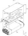
- FIG. 4 is an exploded perspective view of the cooling and venting unit in the battery module of FIG. 3 .
- the battery module 10 includes a cell assembly 100 including a plurality of stacked battery cells 111, a module case 200 and the cooling and venting unit 300.
- the battery module 10 includes the cooling and venting unit 300 to dissipate heat from the battery module 10 and vent gas while preventing leakage of flames in the event of thermal runaway in the battery cells 111.
- the cooling and venting unit 300 may be a single component into which a cooling device 3 (referred to as a heat sink in the corresponding technical field) and a gas venting device 2 applied to the conventional battery module (see FIG. 1 ) are combined, and may perform a cooling function in normal situation and may be used as a gas vent passage when a thermal event occurs.
- the battery module 10 with the cooling and venting unit 300 will be described in detail below.
- the battery module 10 includes the cell assembly 100 including the battery cells 111 and a busbar frame assembly for electrical connection of the battery cells 111 and the module case 200 accommodating the cell assembly 100.
- the battery cell 111 may include a pouch type battery cell 111.
- the pouch type battery cell 111 is a battery cell including an electrode assembly, a pouch case accommodating the electrode assembly and a pair of electrode leads 112 connected to the electrode assembly, extended from the pouch case and serving as electrode terminals.
- the pair of electrode leads 112 may extend in opposite directions or the same direction in the lengthwise direction ( ⁇ X direction) of the battery cells 111.
- the pouch type battery cells 111 are stacked upright in a direction to form a cell stack 110 and the cell stack 110 is inserted into the module case 200 as shown in FIG. 2 .
- the pouch type battery cell 111 is an example of the battery cell 111 that may be received in the battery module 10. That is, any other type of battery cell may be received in the module case.
- the battery cell that may be received in the module case may include any type of battery cell published before the application was filed, for example, a cylindrical battery cell, a prismatic battery cell or the like.
- the busbar frame assembly includes a busbar frame 120 and busbars 130.
- the busbar frame 120 may be formed from an electrically insulating material by injection molding and approximately in the shape of a plate covering the front or rear side of the cell stack 110, and may have a plurality of lead slots to insert and extract the electrode leads 112 of the battery cells 111 into/from the busbar frame 120.
- the busbars 130 may be formed in the shape of a metal rod of an electrically conductive material such as, for example, copper, aluminum, nickel and may be fixedly mounted on the outer surface of the busbar frame 120.
- the busbars 130 may be disposed on the busbar frame 120 in the same direction as the stack direction of the battery cells 111, and the battery cells 111 may be connected in series and/or in parallel by welding the electrode leads 112 extracted from the busbar frame 120 through the lead slots to the corresponding busbars 130.
- the module case 200 may be the component for protecting the cell assembly 100 from the external environment.
- the module case 200 includes a case body 210 accommodating the cell assembly 100 and an end cover 220 covering the assembled portion of the busbar frame 120 and coupled to the case body 210.
- the module case 200 is made of a metal having high mechanical strength, but may be made of any material having high mechanical strength and heat resistance.
- the case body 210 may be formed in the shape of a rectangular tube including a top plate 211, a bottom plate 212 and two side plates 213,214, and having two open ends in the lengthwise direction and a hollow center.
- the cell assembly 100 may be inserted into the case body 210 by sliding or interference fitting.
- the case body 210 is formed in the shape of a rectangular tube by integrally forming the top plate 211, the bottom plate 212 and the two side plates 213,214, but alternatively, for example, the case body 210 may be formed by combining the bottom plate 212 and the two side plates 213,214 into a 'U frame' and welding the 'U frame' to the top of the top plate 211.
- the cell assembly 100 is placed in the 'U frame', the top of the cell assembly 100 is covered with the top plate 211 and the edge of the top plate 211 is welded to the top of the 'U frame'.
- the end cover 220 may be configured to cover the busbar frame assembly electrically connected to the electrode leads 112, and the edge may be coupled to the open end of the case body 210 by welding and/or snap-fitting. Additionally, for electrical insulation from the busbar frame assembly, the end cover 220 may be, for example, made of an insulating material on the inner side, or coated with an insulating sheet on the inner surface.
- the battery cell 111 generates heat by electrochemical reaction during charging/discharging, and in the event of thermal runaway, accompanied by abnormally rapid temperature rise, flames, sparks and gas may erupt from the battery cell 111 (sparks refer to high temperature particles including an electrode active material and aluminum particles).
- sparks refer to high temperature particles including an electrode active material and aluminum particles.
- they may, for example, act on the other adjacent battery module 10 as a source of fire. Accordingly, it is necessary to prevent flames and sparks from leaking out of the battery module 10 in order to prevent fire from spreading.
- gas is trapped in the battery module 10, the internal pressure rapidly rises, causing destruction or explosion of the battery module 10, and accordingly, it is necessary to properly vent gas out of the battery module 10.
- the battery module 10 includes a gas venting hole 215 for gas venting in the event of thermal runaway in the battery cells 111.
- the gas venting hole 215 may be disposed in the top plate 211 of the case body 210 as shown in FIG. 2 .
- the surrounding temperature of the electrode leads 112 is highest during charging/discharging, and when thermal runaway occurs, there is a high likelihood that gas may be vented from the corresponding region.
- the gas venting hole 215 is disposed near the edge of the top plate 211 of the module case 200 close to the electrode leads 112 of the battery cells 111.
- a metal mesh (not shown) may be installed in the gas venting hole 215. The metal mesh may be used to block flames or sparks when gas passes through the gas venting hole 215.
- this embodiment shows one gas venting hole 215, a plurality of gas venting holes 215 may be provided, and may be disposed at locations that are different from this embodiment.
- the gas escaping in the upward direction from the module case 200 through the gas venting hole 215 may enter the cooling and venting unit 300 shown in FIG. 3 , move along a gas venting channel 312 in the cooling and venting unit 300, and finally, exit through a gas outlet 317 of the cooling and venting unit 300.
- the cooling and venting unit 300 is configured to cool the gas by indirect contact with cooling water while the gas moves along the gas venting channel 312. Accordingly, when the gas exits the battery module 10, since its temperature is not high, it may not cause serious thermal damage to the other adjacent battery module 10.
- cooling and venting unit 300 will be described in more detail.
- the cooling and venting unit 300 includes the gas venting channel 312 and a cooling channel 314 integrally formed in a single body, wherein the gas venting channel 312 is in communication with the gas venting hole 215 of the module case 200 and the cooling channel 314 forms a movement path of a cooling medium.
- the cooling and venting unit 300 is disposed on the outer side of the module case 200, i.e., the top plate 211 of the module case 200 in this embodiment.
- the cooling and venting unit 300 may have a size corresponding to the top plate 211 of the module case 200, and may be mounted on the top plate 211 of the module case 200 such that a gas inlet 316 matches the gas venting hole 215 in the vertical direction.
- gas may enter the gas venting channel 312 through the gas inlet 316 from the gas venting hole 215, and exit through the gas outlet 317 opposite the gas inlet 316 along the gas venting channel 312.
- the cooling channel 314 refers to a channel in which the cooling medium may flow, and has a spatially separated structure from the gas venting channel 312 to prevent the cooling medium from entering the gas venting channel 312.
- the cooling medium may include cooling water, and the cooling medium enters the cooling channel 314 of the cooling and venting unit 300 as indicated by C1 and C3 in FIG. 3 , and like the exemplary configuration of FIG. 6 , cools the battery cells by indirect contact with the battery cells 111 with the top plate 211 of the module case 200 interposed therebetween while moving along the cooling channel 314. Additionally, the cooling medium may leave the cooling and venting unit 300 as indicated by C2 and C4 in FIG. 3 .
- a cooling water supply pipe and a cooling water discharge pipe may be connected to a cooling medium inlet 301 and a cooling medium outlet 303 of the cooling channel 314, respectively. Additionally, heat from the battery module 10 may be transferred by the circulation of cooling water in this way "the cooling water supply pipe -> the cooling channel 314 -> the cooling water discharge pipe -> the heat exchanger -> the cooling water supply pipe -> the cooling channel 314".
- the cooling and venting unit 300 includes a channel plate 310 and a cover plate 320.
- the gas venting channel 312 and the cooling channel 314 may be respectively disposed in two surfaces of the channel plate 310.
- the channel plate 310 may be configured such that the upper surface is used as the gas venting channel 312 and the lower surface is used as the cooling channel 314.
- the channel plate 310 has the gas inlet 316 through which a portion of the channel plate 310 corresponding to the gas venting hole 215 of the module case 200 in an area of contact with the top plate 211 of the module case 200 is open in the thicknesswise direction.
- the channel plate 310 may be made of a metal, and preferably, aluminum (Al) or an aluminum alloy having high thermal conductivity.
- the cover plate 320 may be coupled or attached to the upper surface of the channel plate and configured to air-tightly close the gas venting channel.
- the cover plate 320 may be made of the same material as the channel plate 310, or for example, may be made of a stainless steel (SUS) based or ceramics based material having high heat resistance.
- SUS stainless steel
- the channel plate 310 may include the gas venting channel 312 of the exemplary configuration as shown in FIG. 5 in a first surface 310a, and the cooling channel 314 in a second surface 310b opposite the first surface 310a as shown in FIG. 6 .
- the first surface 310a may include a embossed portion 311 convexly protruding in a predetermined area, and the gas venting channel 312 may be formed in an area surrounded by the embossed portion 311.
- the first surface 310a of the channel plate 310 may include a first embossed portion 311A and a second embossed portion 311B raised higher than the central region on two sides, and the first embossed portion 311A and the second embossed portion 311B may extend in a serpentine pattern along the lengthwise direction (X direction) of the channel plate 310.
- the gas venting channel 312 may be disposed in the central region surrounded by the first embossed portion 311A and the second embossed portion 311B. Additionally, convex parts may be added in the gas venting channel 312 to divide the flow of gas into branches.
- the cover plate 320 may be attached to the first surface 310a to air-tightly close the open top of the gas venting channel 312.
- the cover plate 320 of this embodiment may include a body portion 321 having an area corresponding to the first surface 310a and a bent portion 322 bent and extended downward from the edge of the body portion 321 and surrounding the upper part and the front side (-X direction) of the region in which the gas inlet 316 is present.
- the cover plate 320 and the channel plate 310 may be coupled by welding to ensure sealability.
- the remaining portion of the gas venting channel 312 may be completely closed, except the gas inlet 316 located at one end of the channel plate 310 and the gas outlet 317 located at the other end. Accordingly, as indicated by G1 in FIG. 5 , gas may enter the gas venting channel 312 through the gas inlet 316 from the gas venting hole 215 of the module case 200, move along the gas venting channel 312 and exit through the gas outlet 317 as indicated by G2. Meanwhile, as shown, the gas venting channel 312 is narrow in width and has the path extended in a serpentine pattern from one end of the channel plate 310 to the other end, which makes it difficult for flames or sparks to easily escape the gas venting channel 312.
- the cooling channel 314 may be formed opposite the embossed portion 311 of the first surface 310a in the second surface 310b of the channel plate 310 as shown in FIG. 6 .
- the cooling channel 314 may be a region that is concavely recessed from the surface of the second surface 310b along the shape of the embossed portion 311 by forming the embossed portion 311 in the first surface 310a.
- the cooling channel 314 is disposed opposite the embossed portion 311 of the first surface 310a in the second surface 310b, and the gas venting channel 312 is disposed opposite a convex region 313 between a first cooling channel 314A and a second cooling channel 314B of the second surface 310b in the first surface 310a.
- the gas venting channel 312 may be formed in one surface of the metal plate and the cooling channel 314 may be formed in the opposite surface like this embodiment.
- the open lower part (-Z direction) of the cooling channel 314 may be covered by the upper surface of the module case 200. Accordingly, the remaining portion of the cooling channel 314 except the cooling medium inlet 301 and the cooling medium outlet 303 may be air-tightly closed.
- the cooling medium inlet 301 refers to an entrance of the cooling channel 314 for allowing the cooling medium to enter the cooling channel 314, and the cooling medium outlet 303 refers to an exit of the cooling channel 314 for allowing the cooling medium to exit the cooling channel 314.
- a preset portion of the edges of the second surface 310b may be spaced apart from the upper surface of the module case 200 with a predetermined gap therebetween to form the cooling medium inlet 301 and the cooling medium outlet 303. That is, the cooling medium inlet 301 and the cooling medium outlet 303 may be formed by processing the portion of the two edges of the channel plate 310 along ⁇ X direction so as to be in non-contact with the upper surface of the module case 200.
- a connection port 302 may be mounted in each of the cooling medium inlet 301 and the cooling medium outlet 303.
- the connection port 302 may be used to easily connect an external pipe (not shown) to the cooling medium inlet 301 or the cooling medium outlet 303 and may be effective in improving sealability of the connected part.
- cooling water may enter the cooling channel 314 through the cooling medium inlet 301 as indicated by C1, C3 in FIG. 5 , and cool the battery module 10 while moving along the cooling channel 314 as shown in FIG. 6 , thereby dissipating heat from the battery module 10.
- gas may move upward from the gas venting hole 215 of the module case 200 as indicated by G1 in FIG. 5 , enter the gas venting channel 312 through the gas inlet 316, move along the gas venting channel 312 and exit the cooling and venting unit 300 through the gas outlet 317.
- gas since the channel plate 310 has been cooled down by the cooling water, gas may be cooled down while moving along the gas venting channel 312. Accordingly, according to the present disclosure, since gas is vented out of the battery module 10 after it is cooled down to lower temperature, it may be possible to reduce fire risk of the other adjacent battery module 10 or structure caused by gas venting.
- the battery module 10A according to another embodiment of the present disclosure will be briefly described with reference to FIG. 7 .
- FIG. 7 is a schematic perspective view of the battery module 10A according to another embodiment of the present disclosure.
- the battery module 10A may include the cooling and venting unit 300 on at least one side of the module case 200.
- the gas venting hole 215 may be formed on two sides of the module case 200 and as shown in FIG. 7 , the cooling and venting unit 300 may be attached to the two sides of the module case 200.
- the gas venting channel 312 and the cooling channel 314 of the cooling and venting unit 300 may change depending on the location and number of gas venting holes 215 formed on the side of the module case 200.
- the cooling and venting unit 300 of the above-described embodiment has two cooling medium inlets 301 and two cooling medium outlets 303, while the cooling and venting unit 300 of this embodiment may be configured to have one cooling medium inlet 301 and one cooling medium outlet 303. That is, (unlike the exemplary configuration of FIG. 6 ) the cooling and venting unit 300 attached to the left side of the module case 200 may be configured to allow cooling water to enter the cooling channel 314 through one cooling medium inlet 301 as indicated by C5 in FIG. 7 , move along the cooling channel 314 and exit through one cooling medium outlet 303 as indicated by C6.
- cooling and venting unit 300 attached to the right side of the module case 200 may be configured to allow cooling water to enter the cooling channel 314 through one cooling medium inlet 301 as indicated by C7 in FIG. 7 , move along the cooling channel 314 and exit through one cooling medium outlet 303 as indicated by C8.
- cooling and venting unit 300 attached to the top and two sides of the module case 200
- the scope of protection of the present disclosure is not limited thereto. That is, the cooling and venting unit 300 may be configured to attach to one side of the module case 200 or the bottom of the module case 200.
- the method for manufacturing the battery module 10 includes the steps of receiving the plurality of battery cells 111 in the module case 200, preparing the cooling and venting unit 300 and coupling the cooling and venting unit 300 to the outer surface of the module case 200.
- the step of preparing the cooling and venting unit 300 includes a stamping process of placing a flat metal plate between an upper mold 20 and a lower mold 30, and pressing the metal plate in the vertical direction using the upper mold 20 and the lower mold 30 to form the gas venting channel 312 in one surface of the metal plate and forming the cooling channel 314 in the opposite surface of the metal plate so as to form the channel plate 310.
- any one of the upper mold 20 and the lower mold 30 has an embossed surface along a predesigned shape, and the other has a recessed surface.
- the predesigned shape refers to an intended shape of the gas venting channel 312 or the cooling channel 314.
- a process for attaching the cover plate 320 to one surface of the channel plate 310 may be performed.
- the cover plate 320 is attached to the first surface 310a of the channel plate 310 serving as the gas venting channel 312.
- the cover plate 320 and the channel plate 310 may be, for example, coupled to each other by welding.
- a process of attaching the cooling and venting unit 300 to the outer surface of the module case 200 having the gas venting hole 215 is performed using at least one coupling method of welding, bolting, hooking or adhesion.
- the gas venting device and the cooling device present as two distinct components in the conventional battery module 10 may be formed into a single component by combining the gas venting channel 312 and the cooling channel 314 into the channel plate 310 through the stamping process, and attaching the cooling and venting unit 300 including the channel plate 310 and the cover plate 320 to the outer surface of the module case 200.
- a battery pack (not shown) according to the present disclosure may include at least one battery module 10.
- the battery pack according to the present disclosure may further include a master Battery Management System (BMS) for comprehensively controlling the charge/discharge of the at least one battery module 10, a current sensor, a fuse or the like and a pack case accommodating the above-described components.
- BMS Battery Management System
- the battery pack according to the present disclosure may be used in energy storage device applications, or automotive applications such as electric scooters, electric vehicles or electric hybrid vehicles.
Landscapes
- Chemical & Material Sciences (AREA)
- Chemical Kinetics & Catalysis (AREA)
- Electrochemistry (AREA)
- General Chemical & Material Sciences (AREA)
- Engineering & Computer Science (AREA)
- Manufacturing & Machinery (AREA)
- Secondary Cells (AREA)
- Battery Mounting, Suspending (AREA)
- Gas Exhaust Devices For Batteries (AREA)
Abstract
Description
- The present disclosure relates to a battery module, and more particularly to, a battery module in which a cooling device for dissipating heat generated from the battery module and a gas venting device for gas venting in the event of thermal runaway are formed into a single component.
- The present application claims priority to
Korean Patent Application No. 10-2022-0063317 filed on May 24, 2022 - Secondary batteries are attracting attention as a new source of energy with eco-friendliness and energy efficiency since they notably reduce fossil fuel use and do not produce by-products from the use of energy.
- Accordingly, the use of secondary batteries in various types of devices is increasing. For example, secondary batteries are being used as a source of energy for not only small multifunctional products such as wireless mobile devices or wearable devices but also electric vehicles and hybrid electric vehicles proposed as an alternative to gasoline vehicles and diesel vehicles or energy storage systems (ESSs).
- Lithium secondary batteries used widely in recent years have the operating voltage of about 2.5V to 4.5V of each battery. Accordingly, electric vehicles or energy storage systems requiring large capacity and high output use, as a source of energy, a battery module including lithium secondary batteries connected in series and/or in parallel and a battery pack including battery modules connected in series and/or in parallel.
- The number of lithium secondary batteries in one battery module or the number of battery modules in one battery pack may increase according to the output or capacity of the battery pack required for electric vehicles.
- In case where a fire and explosion occurs, damage to the battery pack including the plurality of lithium secondary batteries may be more serious.
- For example, when an event such as a short between the lithium secondary batteries or an abnormal temperature rise occurs in a certain battery module, a large amount of venting gas may be produced in the lithium secondary batteries, and when degradation gets worse, flames and high temperature sparks including electrode active materials and aluminum particles may occur, and the flames and high temperature sparks may erupt from the corresponding battery module along with venting gas. The erupting flames and high temperature sparks cause thermal damage to the other battery modules adjacent to the battery module in which the fire occurred, accelerating the spread of the fire to the other battery modules.
- Accordingly, since ensuring fire safety is important to the battery pack for vehicles, it is necessary to vent the venting gas out of the battery module while preventing the flames or sparks from escaping in order to prevent or delay fire propagation or explosion risks of the battery modules. Moreover, it is important to keep battery cells at optimum temperature by dissipating heat generated from the battery cells during charging/discharging.
- To this end, recently, the battery module includes a gas venting device and a cooling device. For example, as shown in
FIG. 1 , thegas venting device 2 may be configured such that it is mounted on top of thebattery module 1 and the inside of thegas venting device 2 is in communication with the inside of thebattery module 1. Thegas venting device 2 serves to vent gas while suppressing leakage of flames in the event of fire in thebattery module 1. Additionally, thecooling device 3 is mounted on bottom of thebattery module 1, has a flow channel for the flow of cooling water inside, and is configured to absorb heat from battery cells by indirect contact between the cooling water and the battery cells. - However, applying the
gas venting device 2 and thecooling device 3 which are separate and distinct components to each battery module is inefficient from the perspective of process/cost/tact time/size optimization of the battery module. - Accordingly, there is a need for the development of a new single component having a combined structure of the two distinct components, the gas venting device and the cooling device to simplify an assembly process of the battery module and reduce the cost and time, and the volume of the final product.
- The present disclosure is designed to solve the above-described problem, and therefore the present disclosure is directed to providing a battery module with a new single component into which a gas venting device and a cooling device are combined and a method for manufacturing the battery module.
- The technical problem to be solved by the present disclosure is not limited to the above-described problems, and these and other problems will be clearly understood by those skilled in the art from the following description.
- A battery module according to the present disclosure may include a plurality of battery cells; a module case accommodating the plurality of battery cells and having a gas venting hole on at least one side; and a cooling and venting unit including a gas venting channel and a cooling channel integrally formed in a single body, and disposed on an outer side of the module case, wherein the gas venting channel forms a movement path of gas in communication with the gas venting hole, and the cooling channel forms a movement path of a cooling medium.
- The cooling and venting unit may include a channel plate having the gas venting channel in a first surface and the cooling channel in a second surface opposite the first surface; and a cover plate covering any one of the first surface and the second surface and coupled to the channel plate.
- The first surface may have a embossed portion convexly protruding in a predetermined area, and the gas venting channel may be provided in an area surrounded by the embossed portion.
- The cooling channel may be formed opposite the embossed portion of the first surface in the second surface, and may be a region which is concavely recessed from a surface of the second surface along a shape of the embossed portion.
- The channel plate may be made of a metal.
- The cover plate may cover the first surface of the channel plate, and the second surface of the channel plate may be disposed facing an outer surface of the module case.
- The cooling and venting unit may have a gas inlet, through which a portion of the channel plate contacting the outer surface of the module case is open in a thicknesswise direction, so that the gas inlet matches the gas venting hole of the module case in a vertical direction.
- The gas inlet and the gas venting channel may be in communication with each other, and the gas venting channel may have a path which is extended in a serpentine pattern from one end of the channel plate to the other end and a gas outlet in communication with outside may be provided at the other end.
- The cooling and venting unit may include a cooling medium inlet on one side of the cooling channel and a cooling medium outlet on the other side of the cooling channel.
- The cooling medium inlet or the cooling medium outlet may be formed by a gap between a preset portion of edges of the second surface and the outer surface of the module case.
- The cooling and venting unit may be coupled to a top of the module case.
- The cooling and venting unit may be coupled to at least one side of the module case.
- According to another aspect of the present disclosure, there may be provided a battery pack including the above-described battery module.
- According to still another aspect of the present disclosure, there may be provided a method for manufacturing the battery module, including: receiving the plurality of battery cells in the module case; preparing the cooling and venting unit; and coupling the cooling and venting unit to an outer surface of the module case, wherein the preparing of the cooling and venting unit includes a stamping process of placing a flat metal plate between an upper mold and a lower mold, and pressing the metal plate in a vertical direction using the upper mold and the lower mold to form the channel plate including the gas venting channel in a surface of the metal plate and the cooling channel in an opposite surface of the metal plate so as to form the channel plate.
- The preparing of the cooling and venting unit may further include a process of attaching the cover plate to one surface of the channel plate.
- The coupling may include a process of attaching the cooling and venting unit to the outer surface of the module case having the gas venting hole using at least one coupling method of welding, bolting, hooking or adhesion.
- According to an aspect of the present disclosure, it may be possible to provide the battery module with the new single component into which the gas venting device and the cooling device are combined.
- More specifically, when compared with the battery module including the gas venting device and the cooling device as separate and distinct components, the cooling and venting unit into which the gas venting device and the cooling device are combined according to the present disclosure may simplify the assembly process of the battery module and reduce the cost and time and the volume of the final product.
- The effect of the present disclosure is not limited to the above-described effects, and these and other effects will be clearly understood by those skilled in the art from this disclosure and the accompanying drawings.
-
-
FIG. 1 is a diagram schematically showing a configuration of a battery module including a gas venting device and a cooling device according to the related art. -
FIG. 2 is a partial exploded perspective view of a battery module except a cooling and venting unit according to an embodiment of the present disclosure. -
FIG. 3 is a schematic perspective view of a battery module according to an embodiment of the present disclosure. -
FIG. 4 is an exploded perspective view of a cooling and venting unit in the battery module ofFIG. 3 . -
FIG. 5 is a diagram showing a first surface of a channel plate ofFIG. 4 . -
FIG. 6 is a diagram showing a second surface of a channel plate ofFIG. 4 . -
FIG. 7 is a schematic perspective view of a battery module according to another embodiment of the present disclosure. -
FIG. 8 is a flowchart of a process of forming a gas venting channel and a cooling channel, respectively, in a front surface and a rear surface of a metal plate according to the present disclosure. - Hereinafter, exemplary embodiments of the present disclosure will be described in detail with reference to the accompanying drawings. Prior to the description, it should be understood that the terms or words used in the specification and the appended claims should not be construed as limited to general and dictionary meanings, but rather interpreted based on the meanings and concepts corresponding to the technical aspect of the present disclosure on the basis of the principle that the inventor is allowed to define terms appropriately for the best explanation. Therefore, the embodiments described herein and illustrations in the accompanying drawings are exemplary embodiments of the present disclosure to describe the technical aspect of the present disclosure and are not intended to be limiting, and thus it should be understood that a variety of other equivalents and modifications could have been made at the time that the application was filed.
-
FIG. 2 is a partial exploded perspective view of a battery module except a cooling and venting unit according to an embodiment of the present disclosure,FIG. 3 is a schematic perspective view of the battery module according to an embodiment of the present disclosure, andFIG. 4 is an exploded perspective view of the cooling and venting unit in the battery module ofFIG. 3 . - Referring to
FIGS. 1 to 4 , thebattery module 10 according to an embodiment of the present disclosure includes acell assembly 100 including a plurality of stackedbattery cells 111, amodule case 200 and the cooling andventing unit 300. - As described in detail below, the
battery module 10 according to the present disclosure includes the cooling andventing unit 300 to dissipate heat from thebattery module 10 and vent gas while preventing leakage of flames in the event of thermal runaway in thebattery cells 111. In particular, the cooling andventing unit 300 according to the present disclosure may be a single component into which a cooling device 3 (referred to as a heat sink in the corresponding technical field) and agas venting device 2 applied to the conventional battery module (seeFIG. 1 ) are combined, and may perform a cooling function in normal situation and may be used as a gas vent passage when a thermal event occurs. - The
battery module 10 with the cooling andventing unit 300 will be described in detail below. - As shown in
FIG. 2 , thebattery module 10 includes thecell assembly 100 including thebattery cells 111 and a busbar frame assembly for electrical connection of thebattery cells 111 and themodule case 200 accommodating thecell assembly 100. - The
battery cell 111 may include a pouchtype battery cell 111. The pouchtype battery cell 111 is a battery cell including an electrode assembly, a pouch case accommodating the electrode assembly and a pair of electrode leads 112 connected to the electrode assembly, extended from the pouch case and serving as electrode terminals. The pair of electrode leads 112 may extend in opposite directions or the same direction in the lengthwise direction (±X direction) of thebattery cells 111. - The pouch
type battery cells 111 are stacked upright in a direction to form acell stack 110 and thecell stack 110 is inserted into themodule case 200 as shown inFIG. 2 . Meanwhile, the pouchtype battery cell 111 is an example of thebattery cell 111 that may be received in thebattery module 10. That is, any other type of battery cell may be received in the module case. For example, the battery cell that may be received in the module case may include any type of battery cell published before the application was filed, for example, a cylindrical battery cell, a prismatic battery cell or the like. - The busbar frame assembly includes a
busbar frame 120 andbusbars 130. - The
busbar frame 120 may be formed from an electrically insulating material by injection molding and approximately in the shape of a plate covering the front or rear side of thecell stack 110, and may have a plurality of lead slots to insert and extract the electrode leads 112 of thebattery cells 111 into/from thebusbar frame 120. - The
busbars 130 may be formed in the shape of a metal rod of an electrically conductive material such as, for example, copper, aluminum, nickel and may be fixedly mounted on the outer surface of thebusbar frame 120. Thebusbars 130 may be disposed on thebusbar frame 120 in the same direction as the stack direction of thebattery cells 111, and thebattery cells 111 may be connected in series and/or in parallel by welding the electrode leads 112 extracted from thebusbar frame 120 through the lead slots to thecorresponding busbars 130. - The
module case 200 may be the component for protecting thecell assembly 100 from the external environment. - The
module case 200 according to this embodiment includes acase body 210 accommodating thecell assembly 100 and anend cover 220 covering the assembled portion of thebusbar frame 120 and coupled to thecase body 210. Themodule case 200 is made of a metal having high mechanical strength, but may be made of any material having high mechanical strength and heat resistance. - As shown in
FIG. 2 , thecase body 210 may be formed in the shape of a rectangular tube including atop plate 211, abottom plate 212 and two side plates 213,214, and having two open ends in the lengthwise direction and a hollow center. Thecell assembly 100 may be inserted into thecase body 210 by sliding or interference fitting. Meanwhile, in this embodiment, thecase body 210 is formed in the shape of a rectangular tube by integrally forming thetop plate 211, thebottom plate 212 and the two side plates 213,214, but alternatively, for example, thecase body 210 may be formed by combining thebottom plate 212 and the two side plates 213,214 into a 'U frame' and welding the 'U frame' to the top of thetop plate 211. In this case, thecell assembly 100 is placed in the 'U frame', the top of thecell assembly 100 is covered with thetop plate 211 and the edge of thetop plate 211 is welded to the top of the 'U frame'. - The
end cover 220 may be configured to cover the busbar frame assembly electrically connected to the electrode leads 112, and the edge may be coupled to the open end of thecase body 210 by welding and/or snap-fitting. Additionally, for electrical insulation from the busbar frame assembly, theend cover 220 may be, for example, made of an insulating material on the inner side, or coated with an insulating sheet on the inner surface. - Meanwhile, the
battery cell 111 generates heat by electrochemical reaction during charging/discharging, and in the event of thermal runaway, accompanied by abnormally rapid temperature rise, flames, sparks and gas may erupt from the battery cell 111 (sparks refer to high temperature particles including an electrode active material and aluminum particles). In this instance, when flames and sparks are released from thebattery module 10, they may, for example, act on the otheradjacent battery module 10 as a source of fire. Accordingly, it is necessary to prevent flames and sparks from leaking out of thebattery module 10 in order to prevent fire from spreading. However, when gas is trapped in thebattery module 10, the internal pressure rapidly rises, causing destruction or explosion of thebattery module 10, and accordingly, it is necessary to properly vent gas out of thebattery module 10. - The
battery module 10 according to the present disclosure includes agas venting hole 215 for gas venting in the event of thermal runaway in thebattery cells 111. Specifically, thegas venting hole 215 may be disposed in thetop plate 211 of thecase body 210 as shown inFIG. 2 . In the case of the pouchtype battery cell 111, the surrounding temperature of the electrode leads 112 is highest during charging/discharging, and when thermal runaway occurs, there is a high likelihood that gas may be vented from the corresponding region. In this embodiment, thegas venting hole 215 is disposed near the edge of thetop plate 211 of themodule case 200 close to the electrode leads 112 of thebattery cells 111. Additionally, a metal mesh (not shown) may be installed in thegas venting hole 215. The metal mesh may be used to block flames or sparks when gas passes through thegas venting hole 215. - Although this embodiment shows one
gas venting hole 215, a plurality ofgas venting holes 215 may be provided, and may be disposed at locations that are different from this embodiment. - The gas escaping in the upward direction from the
module case 200 through thegas venting hole 215 may enter the cooling andventing unit 300 shown inFIG. 3 , move along agas venting channel 312 in the cooling andventing unit 300, and finally, exit through agas outlet 317 of the cooling andventing unit 300. - In particular, the cooling and
venting unit 300 is configured to cool the gas by indirect contact with cooling water while the gas moves along thegas venting channel 312. Accordingly, when the gas exits thebattery module 10, since its temperature is not high, it may not cause serious thermal damage to the otheradjacent battery module 10. - Hereinafter, the cooling and
venting unit 300 will be described in more detail. - The cooling and
venting unit 300 includes thegas venting channel 312 and acooling channel 314 integrally formed in a single body, wherein thegas venting channel 312 is in communication with thegas venting hole 215 of themodule case 200 and thecooling channel 314 forms a movement path of a cooling medium. The cooling andventing unit 300 is disposed on the outer side of themodule case 200, i.e., thetop plate 211 of themodule case 200 in this embodiment. - That is, as shown in
FIGS. 3 and4 , the cooling andventing unit 300 may have a size corresponding to thetop plate 211 of themodule case 200, and may be mounted on thetop plate 211 of themodule case 200 such that agas inlet 316 matches thegas venting hole 215 in the vertical direction. When the cooling andventing unit 300 is mounted on thetop plate 211 of themodule case 200, gas may enter thegas venting channel 312 through thegas inlet 316 from thegas venting hole 215, and exit through thegas outlet 317 opposite thegas inlet 316 along thegas venting channel 312. - The cooling
channel 314 refers to a channel in which the cooling medium may flow, and has a spatially separated structure from thegas venting channel 312 to prevent the cooling medium from entering thegas venting channel 312. The cooling medium may include cooling water, and the cooling medium enters the coolingchannel 314 of the cooling andventing unit 300 as indicated by C1 and C3 inFIG. 3 , and like the exemplary configuration ofFIG. 6 , cools the battery cells by indirect contact with thebattery cells 111 with thetop plate 211 of themodule case 200 interposed therebetween while moving along the coolingchannel 314. Additionally, the cooling medium may leave the cooling andventing unit 300 as indicated by C2 and C4 inFIG. 3 . - Although not shown for convenience, a cooling water supply pipe and a cooling water discharge pipe may be connected to a cooling
medium inlet 301 and a coolingmedium outlet 303 of thecooling channel 314, respectively. Additionally, heat from thebattery module 10 may be transferred by the circulation of cooling water in this way "the cooling water supply pipe -> the cooling channel 314 -> the cooling water discharge pipe -> the heat exchanger -> the cooling water supply pipe -> the coolingchannel 314". - As shown in
FIG. 4 , the cooling andventing unit 300 includes achannel plate 310 and acover plate 320. - The
gas venting channel 312 and thecooling channel 314 may be respectively disposed in two surfaces of thechannel plate 310. For example, thechannel plate 310 may be configured such that the upper surface is used as thegas venting channel 312 and the lower surface is used as the coolingchannel 314. Additionally, thechannel plate 310 has thegas inlet 316 through which a portion of thechannel plate 310 corresponding to thegas venting hole 215 of themodule case 200 in an area of contact with thetop plate 211 of themodule case 200 is open in the thicknesswise direction. Additionally, thechannel plate 310 may be made of a metal, and preferably, aluminum (Al) or an aluminum alloy having high thermal conductivity. - The
cover plate 320 may be coupled or attached to the upper surface of the channel plate and configured to air-tightly close the gas venting channel. Thecover plate 320 may be made of the same material as thechannel plate 310, or for example, may be made of a stainless steel (SUS) based or ceramics based material having high heat resistance. - More specifically, the
channel plate 310 may include thegas venting channel 312 of the exemplary configuration as shown inFIG. 5 in afirst surface 310a, and thecooling channel 314 in asecond surface 310b opposite thefirst surface 310a as shown inFIG. 6 . - The
first surface 310a may include aembossed portion 311 convexly protruding in a predetermined area, and thegas venting channel 312 may be formed in an area surrounded by the embossedportion 311. - For example, the
first surface 310a of thechannel plate 310 may include a firstembossed portion 311A and a secondembossed portion 311B raised higher than the central region on two sides, and the firstembossed portion 311A and the secondembossed portion 311B may extend in a serpentine pattern along the lengthwise direction (X direction) of thechannel plate 310. Thegas venting channel 312 may be disposed in the central region surrounded by the firstembossed portion 311A and the secondembossed portion 311B. Additionally, convex parts may be added in thegas venting channel 312 to divide the flow of gas into branches. - The
cover plate 320 may be attached to thefirst surface 310a to air-tightly close the open top of thegas venting channel 312. Specifically, thecover plate 320 of this embodiment (seeFIG. 4 ) may include abody portion 321 having an area corresponding to thefirst surface 310a and abent portion 322 bent and extended downward from the edge of thebody portion 321 and surrounding the upper part and the front side (-X direction) of the region in which thegas inlet 316 is present. Preferably, thecover plate 320 and thechannel plate 310 may be coupled by welding to ensure sealability. - When the
cover plate 320 is coupled to thechannel plate 310, the remaining portion of thegas venting channel 312 may be completely closed, except thegas inlet 316 located at one end of thechannel plate 310 and thegas outlet 317 located at the other end. Accordingly, as indicated by G1 inFIG. 5 , gas may enter thegas venting channel 312 through thegas inlet 316 from thegas venting hole 215 of themodule case 200, move along thegas venting channel 312 and exit through thegas outlet 317 as indicated by G2. Meanwhile, as shown, thegas venting channel 312 is narrow in width and has the path extended in a serpentine pattern from one end of thechannel plate 310 to the other end, which makes it difficult for flames or sparks to easily escape thegas venting channel 312. - Meanwhile, the cooling
channel 314 may be formed opposite the embossedportion 311 of thefirst surface 310a in thesecond surface 310b of thechannel plate 310 as shown inFIG. 6 . In addition, the coolingchannel 314 may be a region that is concavely recessed from the surface of thesecond surface 310b along the shape of the embossedportion 311 by forming the embossedportion 311 in thefirst surface 310a. - That is, the cooling
channel 314 is disposed opposite the embossedportion 311 of thefirst surface 310a in thesecond surface 310b, and thegas venting channel 312 is disposed opposite aconvex region 313 between afirst cooling channel 314A and asecond cooling channel 314B of thesecond surface 310b in thefirst surface 310a. For example, when a flat metal plate is stamped using a mold that is embossed in the same shape as the embossedportion 311, thegas venting channel 312 may be formed in one surface of the metal plate and thecooling channel 314 may be formed in the opposite surface like this embodiment. - When the
second surface 310b of thechannel plate 310 having the coolingchannel 314 is disposed facing the upper surface of themodule case 200, the open lower part (-Z direction) of thecooling channel 314 may be covered by the upper surface of themodule case 200. Accordingly, the remaining portion of thecooling channel 314 except the coolingmedium inlet 301 and the coolingmedium outlet 303 may be air-tightly closed. Here, the coolingmedium inlet 301 refers to an entrance of thecooling channel 314 for allowing the cooling medium to enter thecooling channel 314, and the coolingmedium outlet 303 refers to an exit of thecooling channel 314 for allowing the cooling medium to exit the coolingchannel 314. - As shown in
FIG. 6 , a preset portion of the edges of thesecond surface 310b may be spaced apart from the upper surface of themodule case 200 with a predetermined gap therebetween to form the coolingmedium inlet 301 and the coolingmedium outlet 303. That is, the coolingmedium inlet 301 and the coolingmedium outlet 303 may be formed by processing the portion of the two edges of thechannel plate 310 along ±X direction so as to be in non-contact with the upper surface of themodule case 200. - A
connection port 302 may be mounted in each of the coolingmedium inlet 301 and the coolingmedium outlet 303. Theconnection port 302 may be used to easily connect an external pipe (not shown) to the coolingmedium inlet 301 or the coolingmedium outlet 303 and may be effective in improving sealability of the connected part. - By the cooling and
venting unit 300 having the above-described configuration according to an embodiment of the present disclosure, in normal situation, cooling water may enter thecooling channel 314 through the coolingmedium inlet 301 as indicated by C1, C3 inFIG. 5 , and cool thebattery module 10 while moving along the coolingchannel 314 as shown inFIG. 6 , thereby dissipating heat from thebattery module 10. - Additionally, in the event of thermal runaway in the
battery cells 111, gas may move upward from thegas venting hole 215 of themodule case 200 as indicated by G1 inFIG. 5 , enter thegas venting channel 312 through thegas inlet 316, move along thegas venting channel 312 and exit the cooling andventing unit 300 through thegas outlet 317. In this instance, since thechannel plate 310 has been cooled down by the cooling water, gas may be cooled down while moving along thegas venting channel 312. Accordingly, according to the present disclosure, since gas is vented out of thebattery module 10 after it is cooled down to lower temperature, it may be possible to reduce fire risk of the otheradjacent battery module 10 or structure caused by gas venting. - Subsequently, the
battery module 10A according to another embodiment of the present disclosure will be briefly described with reference toFIG. 7 . -
FIG. 7 is a schematic perspective view of thebattery module 10A according to another embodiment of the present disclosure. - The same reference number as the previous drawings indicates the same element, and in the description of the same element, redundant description is omitted and difference(s) between this embodiment and the above-described embodiment will be described.
- The
battery module 10A according to another embodiment of the present disclosure may include the cooling andventing unit 300 on at least one side of themodule case 200. For example, thegas venting hole 215 may be formed on two sides of themodule case 200 and as shown inFIG. 7 , the cooling andventing unit 300 may be attached to the two sides of themodule case 200. In this instance, thegas venting channel 312 and thecooling channel 314 of the cooling andventing unit 300 may change depending on the location and number ofgas venting holes 215 formed on the side of themodule case 200. - Additionally, the cooling and
venting unit 300 of the above-described embodiment has two coolingmedium inlets 301 and two coolingmedium outlets 303, while the cooling andventing unit 300 of this embodiment may be configured to have one coolingmedium inlet 301 and one coolingmedium outlet 303. That is, (unlike the exemplary configuration ofFIG. 6 ) the cooling andventing unit 300 attached to the left side of themodule case 200 may be configured to allow cooling water to enter thecooling channel 314 through one coolingmedium inlet 301 as indicated by C5 inFIG. 7 , move along the coolingchannel 314 and exit through one coolingmedium outlet 303 as indicated by C6. Additionally, the cooling andventing unit 300 attached to the right side of themodule case 200 may be configured to allow cooling water to enter thecooling channel 314 through one coolingmedium inlet 301 as indicated by C7 inFIG. 7 , move along the coolingchannel 314 and exit through one coolingmedium outlet 303 as indicated by C8. - Although the above-described embodiments show examples of the cooling and
venting unit 300 attached to the top and two sides of themodule case 200, the scope of protection of the present disclosure is not limited thereto. That is, the cooling andventing unit 300 may be configured to attach to one side of themodule case 200 or the bottom of themodule case 200. - Hereinafter, a method for manufacturing the
battery module 10 according to the present disclosure will be briefly described. As the process of manufacturing thebattery module 10 has been widely known at the time the application was filed, for clarity of description, a certain description of the method for manufacturing thebattery module 10 known in the corresponding technical field is omitted and the main technical feature will be described. - The method for manufacturing the
battery module 10 according to the present disclosure includes the steps of receiving the plurality ofbattery cells 111 in themodule case 200, preparing the cooling andventing unit 300 and coupling the cooling andventing unit 300 to the outer surface of themodule case 200. - As shown in
FIG. 8 , the step of preparing the cooling andventing unit 300 includes a stamping process of placing a flat metal plate between anupper mold 20 and alower mold 30, and pressing the metal plate in the vertical direction using theupper mold 20 and thelower mold 30 to form thegas venting channel 312 in one surface of the metal plate and forming thecooling channel 314 in the opposite surface of the metal plate so as to form thechannel plate 310. - Here, any one of the
upper mold 20 and thelower mold 30 has an embossed surface along a predesigned shape, and the other has a recessed surface. Additionally, the predesigned shape refers to an intended shape of thegas venting channel 312 or thecooling channel 314. - When the forming of the
channel plate 310 is completed, a process for attaching thecover plate 320 to one surface of thechannel plate 310 may be performed. Preferably, thecover plate 320 is attached to thefirst surface 310a of thechannel plate 310 serving as thegas venting channel 312. In this instance, thecover plate 320 and thechannel plate 310 may be, for example, coupled to each other by welding. - When the cooling and
venting unit 300 is prepared, a process of attaching the cooling andventing unit 300 to the outer surface of themodule case 200 having thegas venting hole 215 is performed using at least one coupling method of welding, bolting, hooking or adhesion. - As described above, the gas venting device and the cooling device present as two distinct components in the
conventional battery module 10 may be formed into a single component by combining thegas venting channel 312 and thecooling channel 314 into thechannel plate 310 through the stamping process, and attaching the cooling andventing unit 300 including thechannel plate 310 and thecover plate 320 to the outer surface of themodule case 200. - Meanwhile, a battery pack (not shown) according to the present disclosure may include at least one
battery module 10. The battery pack according to the present disclosure may further include a master Battery Management System (BMS) for comprehensively controlling the charge/discharge of the at least onebattery module 10, a current sensor, a fuse or the like and a pack case accommodating the above-described components. - The battery pack according to the present disclosure may be used in energy storage device applications, or automotive applications such as electric scooters, electric vehicles or electric hybrid vehicles.
- While the present disclosure has been hereinabove described with regard to a limited number of embodiments and drawings, the present disclosure is not limited thereto and it is apparent that a variety of changes and modifications may be made by those skilled in the art within the technical aspect of the present disclosure and the scope of the appended claims and their equivalents.
- The terms indicating directions such as upper, lower, left, right, front and rear are used for convenience of description, but it is obvious to those skilled in the art that the terms may change depending on the position of the stated element or an observer.
Claims (15)
- A battery module, comprising:a plurality of battery cells;a module case accommodating the plurality of battery cells and having a gas venting hole on at least one side; anda cooling and venting unit including a gas venting channel and a cooling channel integrally formed in a single body, and disposed on an outer side of the module case, wherein the gas venting channel forms a movement path of gas in communication with the gas venting hole, and the cooling channel forms a movement path of a cooling medium.
- The battery module according to claim 1, wherein the cooling and venting unit includes:a channel plate having the gas venting channel in a first surface and the cooling channel in a second surface opposite the first surface; anda cover plate covering any one of the first surface and the second surface and coupled to the channel plate.
- The battery module according to claim 2, wherein the first surface has an embossed portion convexly protruding in a predetermined area, and the gas venting channel is provided in an area surrounded by the embossed portion.
- The battery module according to claim 3, wherein the cooling channel is formed opposite the embossed portion of the first surface in the second surface, and is a region which is concavely recessed from a surface of the second surface along a shape of the embossed portion.
- The battery module according to claim 2, wherein the channel plate is made of a metal.
- The battery module according to claim 2, wherein the cover plate covers the first surface of the channel plate, and
wherein the second surface of the channel plate is disposed facing an outer surface of the module case. - The battery module according to claim 6, wherein the cooling and venting unit has a gas inlet, through which a portion of the channel plate contacting the outer surface of the module case is open in a thicknesswise direction, so that the gas inlet matches the gas venting hole of the module case in a vertical direction.
- The battery module according to claim 7, wherein the gas inlet and the gas venting channel are in communication with each other, and
wherein the gas venting channel has a path which is extended in a serpentine pattern from one end of the channel plate to the other end and a gas outlet in communication with outside is provided at the other end. - The battery module according to claim 6, wherein the cooling and venting unit includes a cooling medium inlet on one side of the cooling channel and a cooling medium outlet on the other side of the cooling channel.
- The battery module according to claim 9, wherein the cooling medium inlet or the cooling medium outlet is formed by a gap between a preset portion of edges of the second surface and the outer surface of the module case.
- The battery module according to claim 1, wherein the cooling and venting unit is coupled to a top of the module case.
- The battery module according to claim 1, wherein the cooling and venting unit is coupled to at least one side of the module case.
- A battery pack comprising the battery module according to any one of claims 1 to 12.
- A method for manufacturing the battery module defined in claim 1, comprising:receiving the plurality of battery cells in the module case;preparing the cooling and venting unit; andcoupling the cooling and venting unit to an outer surface of the module case,wherein the preparing of the cooling and venting unit includes a stamping process of placing a flat metal plate between an upper mold and a lower mold, and pressing the metal plate in a vertical direction using the upper mold and the lower mold to form the channel plate including the gas venting channel in a surface of the metal plate and the cooling channel in an opposite surface of the metal plate so as to form the channel plate.
- The method for manufacturing the battery module according to claim 14, wherein the preparing of the cooling and venting unit further includes a process of attaching the cover plate to one surface of the channel plate, and
wherein the coupling includes a process of attaching the cooling and venting unit to the outer surface of the module case having the gas venting hole using at least one coupling method of welding, bolting, hooking or adhesion.
Applications Claiming Priority (2)
| Application Number | Priority Date | Filing Date | Title |
|---|---|---|---|
| KR1020220063317A KR102659210B1 (en) | 2022-05-24 | 2022-05-24 | A battery module that integrates a gas venting channel and a cooling channel, a battery pack including the same, and a method for manufacturing the battery module |
| PCT/KR2023/006067 WO2023229254A1 (en) | 2022-05-24 | 2023-05-03 | Battery module that integrates gas venting channel and cooling channel, battery pack including same, and method for manufacturing battery module |
Publications (2)
| Publication Number | Publication Date |
|---|---|
| EP4425675A1 true EP4425675A1 (en) | 2024-09-04 |
| EP4425675A4 EP4425675A4 (en) | 2025-05-21 |
Family
ID=88919570
Family Applications (1)
| Application Number | Title | Priority Date | Filing Date |
|---|---|---|---|
| EP23812030.7A Pending EP4425675A4 (en) | 2022-05-24 | 2023-05-03 | Battery module that integrates gas venting channel and cooling channel, battery pack including same, and method for manufacturing battery module |
Country Status (7)
| Country | Link |
|---|---|
| US (1) | US12255301B2 (en) |
| EP (1) | EP4425675A4 (en) |
| JP (1) | JP7782033B2 (en) |
| KR (1) | KR102659210B1 (en) |
| CN (1) | CN118056326A (en) |
| CA (1) | CA3242444A1 (en) |
| WO (1) | WO2023229254A1 (en) |
Families Citing this family (5)
| Publication number | Priority date | Publication date | Assignee | Title |
|---|---|---|---|---|
| KR20220170188A (en) * | 2021-06-22 | 2022-12-29 | 주식회사 엘지에너지솔루션 | Battery module and battery pack including the same |
| KR20250106021A (en) * | 2024-01-02 | 2025-07-09 | 주식회사 엘지에너지솔루션 | Battery pack and Vehicle including the same |
| KR20250106022A (en) * | 2024-01-02 | 2025-07-09 | 주식회사 엘지에너지솔루션 | Battery pack and Vehicle including the same |
| TWI901232B (en) * | 2024-06-26 | 2025-10-11 | 嘉盈鋰源股份有限公司 | Battery module and battery box thereof |
| KR20260044372A (en) * | 2024-09-26 | 2026-04-02 | 주식회사 엘지에너지솔루션 | Battery module, battery pack and vehicle including the same |
Family Cites Families (21)
| Publication number | Priority date | Publication date | Assignee | Title |
|---|---|---|---|---|
| KR960024206A (en) | 1994-12-28 | 1996-07-20 | 구자홍 | Prefabricated Heat Exchanger for Air Conditioner |
| JP4815026B2 (en) * | 2009-07-17 | 2011-11-16 | パナソニック株式会社 | Battery module and battery pack using the same |
| KR20150017402A (en) | 2013-06-10 | 2015-02-17 | 현대하이스코 주식회사 | Fuel cell stack with excellent circulating performance |
| KR101615941B1 (en) | 2013-08-29 | 2016-04-27 | 주식회사 엘지화학 | Battery Module Having Structure for Prevention of Coolant and Venting Gas Mixing |
| KR101743697B1 (en) | 2014-04-14 | 2017-06-20 | 주식회사 엘지화학 | Battery module having separated cooling path and venting path and battery pack including the same |
| US9761918B2 (en) * | 2015-09-10 | 2017-09-12 | Ford Global Technologies, Llc | Vehicle traction battery assembly |
| WO2018123573A1 (en) | 2016-12-27 | 2018-07-05 | パナソニックIpマネジメント株式会社 | Battery module |
| KR101799238B1 (en) | 2017-06-09 | 2017-11-17 | 김국현 | Battery cover assembly |
| WO2019021779A1 (en) | 2017-07-24 | 2019-01-31 | 三洋電機株式会社 | Battery system and vehicle equipped with battery system |
| CN110277533B (en) * | 2018-03-16 | 2020-12-29 | 宁德时代新能源科技股份有限公司 | battery module |
| CN117650327A (en) | 2018-07-31 | 2024-03-05 | 松下知识产权经营株式会社 | battery module |
| KR102142323B1 (en) | 2019-08-27 | 2020-08-07 | 주식회사 티앤지 | Cooling panel structure of battery and method for manufacturing the Cooling panel structure |
| KR102716975B1 (en) * | 2019-10-30 | 2024-10-11 | 주식회사 엘지에너지솔루션 | Battery module, battery rack and energy storage system comprising the battery module |
| KR102937933B1 (en) * | 2020-04-29 | 2026-03-10 | 주식회사 엘지에너지솔루션 | Battery module and battery pack including the same |
| WO2022006894A1 (en) | 2020-07-10 | 2022-01-13 | 宁德时代新能源科技股份有限公司 | Battery and related apparatus therefor, preparation method, and preparation device |
| KR102462632B1 (en) | 2020-09-24 | 2022-11-03 | 주식회사 포스코 | Cooling plate of battery pack |
| KR20220063317A (en) | 2020-11-10 | 2022-05-17 | 주식회사 앤지티(Ngt) | Double window system |
| CN214013020U (en) * | 2020-12-22 | 2021-08-20 | 蜂巢能源科技有限公司 | Water cooling plate and battery module |
| KR20220170188A (en) * | 2021-06-22 | 2022-12-29 | 주식회사 엘지에너지솔루션 | Battery module and battery pack including the same |
| EP4175017A3 (en) * | 2021-10-05 | 2023-11-01 | Samsung SDI Co., Ltd. | Cell cooling cover for a battery module |
| US20230246289A1 (en) * | 2022-02-01 | 2023-08-03 | Samsung Sdi Co., Ltd. | Battery system with active cooling of venting channel |
-
2022
- 2022-05-24 KR KR1020220063317A patent/KR102659210B1/en active Active
-
2023
- 2023-05-03 CA CA3242444A patent/CA3242444A1/en active Pending
- 2023-05-03 EP EP23812030.7A patent/EP4425675A4/en active Pending
- 2023-05-03 WO PCT/KR2023/006067 patent/WO2023229254A1/en not_active Ceased
- 2023-05-03 US US18/712,633 patent/US12255301B2/en active Active
- 2023-05-03 JP JP2024523966A patent/JP7782033B2/en active Active
- 2023-05-03 CN CN202380013866.3A patent/CN118056326A/en active Pending
Also Published As
| Publication number | Publication date |
|---|---|
| WO2023229254A1 (en) | 2023-11-30 |
| JP7782033B2 (en) | 2025-12-08 |
| US12255301B2 (en) | 2025-03-18 |
| CA3242444A1 (en) | 2023-11-30 |
| KR20230163704A (en) | 2023-12-01 |
| US20240332668A1 (en) | 2024-10-03 |
| CN118056326A (en) | 2024-05-17 |
| KR102659210B1 (en) | 2024-04-18 |
| JP2024539236A (en) | 2024-10-28 |
| EP4425675A4 (en) | 2025-05-21 |
Similar Documents
| Publication | Publication Date | Title |
|---|---|---|
| EP4425675A1 (en) | Battery module that integrates gas venting channel and cooling channel, battery pack including same, and method for manufacturing battery module | |
| US12051789B2 (en) | Battery pack | |
| US12051790B2 (en) | Battery module and battery pack comprising same | |
| EP3664187B1 (en) | Cylindrical battery cell assembly with improved space utilization and safety, and battery module comprising same | |
| EP4027404A1 (en) | Battery module, battery pack, and vehicle | |
| KR101447062B1 (en) | Battery Module and Battery Pack Containing the Same | |
| KR101723016B1 (en) | Battery Assembly Comprising Battery Frame Assembly | |
| US20240213576A1 (en) | Battery module and battery pack comprising the same | |
| CN116438696B (en) | Battery cell, battery, power utilization device, and device and method for preparing battery cell | |
| KR102880677B1 (en) | Battery module and, battery pack and vehicle including same | |
| EP4376173A1 (en) | Battery rack and power storage device comprising same | |
| JP7292658B2 (en) | Busbar module and its manufacturing method | |
| KR102798697B1 (en) | Secondary battery and method of manufacturing the same | |
| EP4391212A1 (en) | Battery pack | |
| US12021212B2 (en) | Battery module, and battery pack and vehicle comprising same | |
| EP4432446A1 (en) | Battery module and, battery pack comprising same and vehicle comprising same | |
| EP4618249A1 (en) | Battery module | |
| US20250210801A1 (en) | Rechargeable battery, rechargeable battery pack and method of manufacturing cap plate of rechargeable battery | |
| EP4645532A1 (en) | Battery module, and battery pack and vehicle including same | |
| KR20260006261A (en) | Battery pack | |
| KR20260011636A (en) | Unit cell assembly, battery module comprising same, battery pack and vehicle | |
| CN118202514A (en) | Battery module, battery pack and vehicle including the battery module |
Legal Events
| Date | Code | Title | Description |
|---|---|---|---|
| STAA | Information on the status of an ep patent application or granted ep patent |
Free format text: STATUS: THE INTERNATIONAL PUBLICATION HAS BEEN MADE |
|
| PUAI | Public reference made under article 153(3) epc to a published international application that has entered the european phase |
Free format text: ORIGINAL CODE: 0009012 |
|
| STAA | Information on the status of an ep patent application or granted ep patent |
Free format text: STATUS: REQUEST FOR EXAMINATION WAS MADE |
|
| 17P | Request for examination filed |
Effective date: 20240527 |
|
| AK | Designated contracting states |
Kind code of ref document: A1 Designated state(s): AL AT BE BG CH CY CZ DE DK EE ES FI FR GB GR HR HU IE IS IT LI LT LU LV MC ME MK MT NL NO PL PT RO RS SE SI SK SM TR |
|
| A4 | Supplementary search report drawn up and despatched |
Effective date: 20250423 |
|
| RIC1 | Information provided on ipc code assigned before grant |
Ipc: H01M 50/271 20210101ALI20250415BHEP Ipc: H01M 50/30 20210101ALI20250415BHEP Ipc: H01M 50/209 20210101ALI20250415BHEP Ipc: H01M 10/6567 20140101ALI20250415BHEP Ipc: H01M 10/6556 20140101ALI20250415BHEP Ipc: H01M 10/613 20140101ALI20250415BHEP Ipc: H01M 50/211 20210101ALI20250415BHEP Ipc: H01M 50/367 20210101ALI20250415BHEP Ipc: H01M 50/35 20210101AFI20250415BHEP |
|
| DAV | Request for validation of the european patent (deleted) | ||
| DAX | Request for extension of the european patent (deleted) |